Eaton easyE4 Manual
Hide thumbs
Also See for easyE4:
- Manual (747 pages) ,
- Application note (29 pages) ,
- Instruction leaflet (9 pages)
Table of Contents
Advertisement
Quick Links
Advertisement
Chapters
Table of Contents

Related Manuals for Eaton easyE4


Summary of Contents for Eaton easyE4
- Page 1 02/24 MN050009EN Manual easyE4 manual ...
-
Page 2: Company Information
No part of this manual may be reproduced, stored in a retrieval system, or transmitted in any form or by any means, electronic, mechanical, photocopying, micro-filming, recording or oth- erwise, without the prior written permission of Eaton Industries GmbH, Bonn. Subject to alteration. -
Page 3: Before Starting With The Installation
DANGER! Hazardous electrical voltage! Before starting with the installation Installation requires qualified electrician desktop devices and portable devices only when the housing is closed. Disconnect the power supply of the device. Measures should be taken to ensure the proper Secure against retriggering ... -
Page 5: Table Of Contents
Legal disclaimer 0.1.4 Short designations 0.1.5 Writing conventions 0.1.5.1 Warning labels 0.1.5.2 Additional information for use Description of easyE4 control relay Use as intended Function Device models - versions and part nos. 1.3.1 Base device versions 1.3.2 Expansion versions 1.3.3... -
Page 6: Fig. 21: Connect Digital Counter Inputs
Prerequisites for the location of use 2.1.1 Installation position 2.1.1.1 Temperatures 2.1.1.2 Aeration and de-aeration Unpacking and checking the equipment supplied Mounting 2.3.1 Mounting easyE4 control relays 2.3.1.1 Installation on mounting rail 2.3.1.2 Screw mounting 2.3.1.3 Dismounting of a device Connection terminals 2.4.1 Screw terminals 2.4.2... - Page 7 Installation instructions Commissioning Initial commissioning Daily operation Switch on 3.3.1 Startup behavior of easyE4 control relay with LED indicators 106 3.3.2 Startup behavior of control relay easyE4 with a display and keypad 3.3.3 Startup behavior of base devices with connected expansion devices 3.3.4...
- Page 8 Automatic booting of the memory card 3.6.1 Preparing the card in the device for booting with easySoft 8 3.6.2 Preparing the card in the easyE4 device for booting with easySoft 8 3.6.3 Preparing the card for booting on the easyE4 device itself...
- Page 9 Draw a wiring diagram 4.5.2 Testing the circuit diagram 4.5.3 Control options in RUN mode 4.5.4 Delete Program Transfer program to the easyE4 device 4.6.1 Transfer with a microSD memory card 4.6.2 Establishing an Ethernet connection Programming on the device Program...
- Page 10 Organizing marker ranges 5.7.7 Operand table 5.7.8 Retentive markers 5.7.9 Internal marker ranges in function blocks Function blocks Manufacturer function blocks 6.1.1 Timer modules 6.1.1.1 HW - Weekly timer (Hour Week) 6.1.1.2 HY - Year time switch (Hora Year) easyE4 02/24 MN050009EN Eaton.com...
- Page 11 Data and register function blocks 6.1.5.1 BC - Block comparison 6.1.5.2 BT - Block transfer 6.1.5.3 DB - Data function block 6.1.5.4 MX - Data multiplexer 6.1.5.5 RE - Recipe records 6.1.5.6 SR - Shift register 6.1.5.7 TB - Table function easyE4 02/24 MN050009EN Eaton.com...
- Page 12 6.2.2.2 Operating principle 6.2.2.3 The function block and its parameters 6.2.2.4 Other 6.2.3 IT - Time-controlled interrupt function block 6.2.3.1 General 6.2.3.2 Operating principle 6.2.3.3 The function block and its parameters 6.2.3.4 Other UF - User function block easyE4 02/24 MN050009EN Eaton.com...
- Page 13 Enabling / disabling the RUN START option 7.9.1.1 Configuration on a base device with a display 7.9.2 Enabling / disabling the CARD START option 7.9.2.1 Configuration on a base device with a display 7.9.2.2 Configuration in easySoft 8 easyE4 02/24 MN050009EN Eaton.com...
- Page 14 What happens if you forget your password or enter the wrong password? 7.15 Configuring the microSD card and device ID 7.16 Time and Date setting How easyE4 works internally Program execution Transferring an existing circuit diagram Device information NET network Operating states easyE4 Controlling the backlight with operands 8.6.1...
- Page 15 8 10.11.6 Installing the Eaton easyE4 root certificate separately 10.11.7 How can I check to make sure that the Eaton easyE4 root cer- tificate has been successfully installed on my PC/tablet/cell phone? 10.12 Setting up a NET group 10.12.1...
- Page 16 Web client 10.15 Setting up the e-mail function 10.15.1 E-mail tab 10.16 easy communication modules 10.16.1 easyE4 as a SWD coordinator 10.16.1.1 SmartWire-DT - The System 10.16.1.2 EASY-COM-SWD-… easy communication module 10.16.1.3 LED status messages on the EASY-COM-SWD-… com- munication module 10.16.2...
- Page 17 10.17 Modbus TCP 10.17.1 easyE4 as a Modbus TCP client 10.17.2 easyE4 as a Modbus TCP server 10.17.2.1 Programming communication with Modbus TCP 10.17.2.2 Modbus TCP error handling 10.18 Convenient visualization for easyE4 10.18.1 easyE Remote Touch Display 10.18.2 HMI Touchdisplays Faults 11.1...
- Page 18 A.5.3 Product information A.5.4 Product training A.5.5 Community A.5.6 Cybersecurity A.5.7 Internet links Sample projects Alphabetical index List of Figures Glossary easyE4 02/24 MN050009EN Eaton.com...
-
Page 19: About This Manual
0.1 About this manual 0.1 About this manual This manual contains all the information you will need in order to use the easyE4 con- trol relay safely and effectively. The easyE4 manual is considered an integral part of the devices and must always be readily available in the device's close proximity so that users have access to it. -
Page 20: List Of Revisions
6th edition ware version 08 06/2023 Bugfix package for easySoft V8.01 and ✓ ✓ 7th edition (DE configuration with e4setting.ini file only) 02/2024 Extension with visualization view / ✓ ✓ 8th edition easyE RTD Advanced easyE4 02/24 MN050009EN Eaton.com... -
Page 21: Target Group
Installation requires qualified electrician Follow the safety instructions for the easyE4! The section on safety instructions must be read and understood by everyone who will be working with the easyE4 before the actual work is performed. WARNING Incomplete operator manual copies... -
Page 22: Legal Disclaimer
Hazards posed by the control relay cannot be ruled out if the safety instructions are not observed – especially if the control relay is installed and commissioned by inad- equately qualified personnel or if it is used improperly. Eaton assumes no liability for any damages resulting from cases such as these. -
Page 23: Short Designations
Type with terminal type screw terminals EASY-E4-...-...E1P Type with push-in terminals easySoft 8 Programming software for easyE4 devices EASY-COM-... easy communication modules for easyE4 devices For the exact designation for your easyE4, please refer to the inscription on the device. easyE4 02/24 MN050009EN Eaton.com... -
Page 24: Writing Conventions
Warns of the possibility of hazardous situations that can cause injury. Property damage warning NOTICE Warns about the possibility of material damage. Prohibited use Prohibited uses, actions, etc. Prohibition signs interdict actions or the use of certain objects easyE4 02/24 MN050009EN Eaton.com... -
Page 25: Additional Information For Use
Documents (such as manuals) are listed after the icon together with the cor- responding name and Eaton number. Publication title For identifying the Eaton publication code Links to external Internet addresses. They will be shown after the icon. Destination address without http(s)://www. - Page 26 0.1 About this manual easyE4 02/24 MN050009EN Eaton.com...
-
Page 27: Description Of Easye4 Control Relay
1. Description of easyE4 control relay 1.1 Use as intended The easyE4 device is a programmable switching and controller device that is used to replace relay and contactor controls. It is intended exclusively for monitoring, operating, and controlling machines and sys- tems, as well as building and automation services for commercial buildings. -
Page 28: Function
Structured Text (ST), and easy Device Programming (EDP) on device and in easySoft 8 easyE4 base devices combine the functions of a control relay and an input device in one single unit The Ethernet port makes it possible to integrate the base device into a network. - Page 29 All the function blocks available are provided in a list → Section "Function blocks", page 241 If you wish to wire a easyE4 device via your PC, i.e. create a circuit diagram, use the easySoft 8 ...
-
Page 30: Device Models - Versions And Part Nos
The functionality for each base device can be customized with up to 11 expansions from the easyE4 series. EASY-COM-... easy communication modules can be used with an easyE4 base device starting with generation 05. 1.3.1 Base device versions The available base device versions are different from each other in terms of: ... - Page 31 1. Description of easyE4 control relay 1.3 Device models - versions and part nos. EASY-E4-UC-12RC1(P), EASY-E4-UC-12RCX1(P), EASY-E4-AC-12RC1(P) EASY-E4-AC-12RCX1(P) ① ② ① ② ⑧ ⑧ ⑧ ⑧ ⑫ ⑥ ⑪ ⑦ ⑦ ⑩ ⑥ ⑨ ④ ④ ⑤ ⑤ ③ ③...
-
Page 32: Expansion Versions
1. Description of easyE4 control relay 1.3 Device models - versions and part nos. 1.3.2 Expansion versions The available input and output expansion devices are different from each other in terms of: The type of operating voltage - UC, DC or AC, ... - Page 33 1. Description of easyE4 control relay 1.3 Device models - versions and part nos. EASY-E4-...-16... EASY-E4-DC-8TE1(P) EASY-E4-...-8... ① ② ① ② ① ② ⑬ ⑧ ⑬ ⑧ ⑬ ⑧ ⑪ ⑪ ⑪ ③ ③ ③ EASY-E4-DC-16TE1(P) EASY-E4-DC-4PE1(P) EASY-E4-DC-6AE1(P) ①...
-
Page 34: Overview Of Available Easye4 Devices
1.3 Device models - versions and part nos. 1.3.3 Overview of available easyE4 devices Make sure to take advantage of the EATON online catalog. Enter "easy" into the search box and the catalog will take you directly to the corresponding product group in the Automation, Control and visualization section. - Page 35 Featuring screw terminals EASY-COM-...1 Catalog No. and type Description 199452 - EASY-COM-SWD-C1 For using the easyE4 control relay as a SmartWire-DT coordinator in a SmartWire-DT line 199453 - EASY-COM-RTU-M1 For using the easyE4 control relay with Modbus RTU easyE4 02/24 MN050009EN Eaton.com...
-
Page 36: What The Different Parts Of The Part Number Mean
1.4 What the different parts of the part number mean The part number includes information that specifies the version and model of the spe- cific device being used. The Part number can be found at the front of the easyE4. Tab. 2: Key to part numbers easy-E4 ... -
Page 37: Accessory Devices
1. Description of easyE4 control relay 1.5 Accessory devices 1.5 Accessory devices In addition to the expansions, there are additional accessories available for easyE4 control relays. NOTICE Only use original accessories. Order accessories through your supplier or through the EATON... - Page 38 1. Description of easyE4 control relay 1.5 Accessory devices Starter packages We have various packages with limited availability that are intended to make it easier to get started with control applications. Cat No. and type Starter kit consists of: 198514 XV100-BOX-E4-DC1...
-
Page 39: Nameplate
1. Description of easyE4 control relay 1.6 Nameplate 1.6 Nameplate The device can be identified by checking the nameplate on its side. This nameplate includes the following information: Manufacturer Generation (hardware revision) Operational voltage Heat dissipation information ... -
Page 40: Easysoft 8 Programming Software
1.8 easySoft 8 programming software 1.8 easySoft 8 programming software easyE4 control relays are designed to be programmed with the easySoft 8 pro- gramming software program. This program was developed specifically for this series of devices, and makes it possible to quickly, conveniently, and easily integrate avail- able functions into a circuit diagram and use the result as a control program. -
Page 41: System Requirements
1. Description of easyE4 control relay 1.8 easySoft 8 programming software Application examples Support has provided a number of applications that are available for download as ZIP files from the Software Download Center. Download Center - Software Eaton.com/software/Anwendungsbeispiele/easy/Deutsch Eaton.com/software/Application Samples/easy/English These examples come with a task description, the circuit diagram, and the easySoft project (in the EDP and LD programming languages as of this writing). -
Page 42: Safety Regulations
Follow the safety instructions for the easyE4! The section on safety instructions must be read and understood by everyone who will be working with the easyE4 before the actual work is performed. NOTICE Pay attention to the hazard severity levels used throughout this doc- umentation whenever a hazard is indicated. -
Page 43: Device Documentation
Additional parts of the documentation and information for the easyE4, including the installation instructions, can be found at the Eaton Download Center - Documentation and at the product pages on the Internet Eaton.com/documentation... -
Page 44: Prerequisites For Proper Operation
1. Description of easyE4 control relay 1.9 Safety regulations 1.9.2.5 Prerequisites for proper operation In order for the device to be able to meet the contractually stipulated terms, the fol- lowing must be observed: Only qualified personnel should be allowed to work with the device. -
Page 45: Device-Specific Hazards
1. Description of easyE4 control relay 1.9 Safety regulations 1.9.3 Device-specific hazards CAUTION DESTRUCTION The easyE4 should only be opened by the manufacturer or by an authorized center. Operate the device until only with the enclosure fully closed and sealed. CAUTION ELECTROSTATIC DISCHARGE Do not touch components (e.g., connector pins) that are electrostatic-... - Page 46 Ground connection characteristics: Wire cross-sectional area ≧ 1.5 mm², length ≦ 350 mm easyE4 needs to be connected to the conductive structure in, e.g., the control panel using the central earth point (earthing screw). This method of earthing is mandatory required for proper function.
- Page 47 CAUTION UV LIGHT Plastics will become brittle when exposed to UV light. This artificial aging will reduce the easyE4 unit's lifespan. Protect the device from direct sunlight and other sources of UV radiation. easyE4 02/24 MN050009EN Eaton.com...
- Page 48 1. Description of easyE4 control relay 1.9 Safety regulations CAUTION POINTY, SHARP OBJECTS AND CORROSIVE LIQUIDS When cleaning the device: Do not use any pointy or sharp objects (e.g., knives). Do not use aggressive or abrasive cleaning products or solvents.
-
Page 49: Engineering
1. Description of easyE4 control relay 1.10 Engineering 1.10 Engineering The easyE4 series makes it possible to combine multiple voltage variants. Each base device can be wired with up to 11 EASY-E4-...-...E1(P) expansions with different power supplies. 1.10.1 Length of Signal input cables 1.10.1.1 Digital inputs... -
Page 50: Analog Inputs
1. Description of easyE4 control relay 1.10 Engineering 1.10.1.2 Analog inputs On the EASY-E4-DC-6AE1(P) expansion, 4 analog input signals are available with a maximum line length of 10 m (shielded). On the EASY-E4-DC-4PE1(P) expansion with temperature recording, 4 analog input signals are available with a maximum line length of 30 m (unshielded). -
Page 51: Notes For Connection Of Easy-E4-Ac
1. Fig. 4: AC input with suppression diode easyE4 AC Alternatively, ballast M22-XLED-T (item no. 231079) can be used as a diode. -
Page 52: Fig. 5: Ac Input With Ballast M22-Xled-T
1. Description of easyE4 control relay 1.10 Engineering M22-XLED-T Fig. 5: AC input with ballast M22-XLED-T Switching the I7/I8 inputs on AC base devices Neon lamps with a maximum residual current of 2 mA / 1 mA at 230 V/115 V can be connected to I7 and I8. -
Page 53: Fig. 7: Limitation Of The Input Current Through Resistors
1. Description of easyE4 control relay 1.10 Engineering 100 nF/275 V ~ 1 kΩ Fig. 7: Limitation of the input current through resistors As an alternative to the condenser, you can use the M22-XLED230-T ballast (item no. 231080). It includes a 150 nF condenser in series with a 2k resistor and this increases the current by 9.9 mA at 230 V/50 Hz and by 6.5 mA at 115 V/60 Hz. -
Page 54: Analog Signals
1. Description of easyE4 control relay 1.10 Engineering 1.10.4 Analog signals DANGER Analog signals are more sensitive to interference than digital signals, which is why the signal cables should be carefully routed and con- nected. An incorrect connection can lead to unwanted switching states. -
Page 55: Notes On Connecting An Easy Communication Module
05. (ID on the nameplate, → page 35) The easy communication module needs to be connected to the left side of the easyE4 base device, while an I/O expansion for easyE4 control relays is connected to the right side. - Page 56 1. Description of easyE4 control relay 1.10 Engineering easyE4 02/24 MN050009EN Eaton.com...
-
Page 57: Installation
2. Installation CAUTION Installation requires qualified electrician easyE4 devices must be installed and wired exclusively by an electrician or a person is familiar with electrical installation rules and practices. The devices are installed in the following order: 1. Mounting base device 2. -
Page 58: Prerequisites For The Location Of Use
If necessary, reinforcing elements must be installed/ad- ded. 2.1.1 Installation position easyE4 devices are intended to be flush mounted in control cabinets, control panels, service distribution boards, or control consoles from behind. The following must be taken into account when selecting the installation position: ... -
Page 59: Temperatures
Provide sufficient volume for the exchange of air in the switch cabinet etc. The specified free space around the easyE4 measures:a, b, c ≧ 30 mm (1,2"). When installing the easyE4 in complex systems together with other assemblies, you must ensure that there will be enough air circulation in order to prevent over- heating. -
Page 60: Unpacking And Checking The Equipment Supplied
EASY-COM-RTU-M1(P) Bus connector plug Installation instructions IL050035ZU The easyE4 series is sturdily built, but the components inside it are sensitive to excessively strong vibrations and/or mechanical shock. Accordingly, make sure to protect the easyE4 from mechanical loads that exceed the scope of the unit's intended use. - Page 61 2. Installation 2.2 Unpacking and checking the equipment supplied Missing parts or damage If you notice anything wrong, please contact your distributor or Eaton Service +49 (0) 180 5 223822 (de,en) easyE4 02/24 MN050009EN Eaton.com...
-
Page 62: Mounting
ZB4-101-GF1 mounting feet. 2.3.1 Mounting easyE4 control relays Install the easyE4 control relay in a control panel, service distribution board, or enclosure so that the power supply and terminal connections cannot be touched dir- ectly during operation. -
Page 63: Fig. 9: Min. Clearance Of 3 Cm
2.3 Mounting > 30 mm > 30 mm (> 1.2") (> 1.2") Fig. 9: Min. clearance of 3 cm Snap the base device and every expansion onto a mounting rail or mount every device using ZB4-101-GF1 device feet easyE4 02/24 MN050009EN Eaton.com... -
Page 64: Fig. 10: Assembling A Base Device With Expansions
I/O expansion for easyE4 control relays Local expansion devices are connected directly to the right of the basic unit. You can use the connector to connect the easyE4 base device to up to 11 expansions and assemble them into a single device block. -
Page 65: Fig. 11: Assembling The Base Device With An Easy Communication Module As
The easy communication module needs to be placed directly next to the base device, on the microSD side. You can use the connector to connect the easyE4 base device to an easy com- munication module and assemble them into a single device block. -
Page 66: Installation On Mounting Rail
2. Slide the expansion until it is resting flush against the previous expansion. 3. Lightly push the device down and against the mounting rail until it snaps into place over the mounting rail's lower lip. easyE4 02/24 MN050009EN Eaton.com... - Page 67 There will be the following electrical isolation at the local expansion connection between the base device and the expansion device: Basic isolation, 400 V (+10%). Safe isolation, 240 V (+10%). The base device, expansion device, and easy communication module can be powered with different power supplies. easyE4 02/24 MN050009EN Eaton.com...
-
Page 68: Screw Mounting
2. Installation 2.3 Mounting 2.3.1.2 Screw mounting Fixing brackets ZB4-101-GF1 that can be inserted on the rear of the easyE4 device are required for screw mounting. These feet are available as an accessory – please refer to → Section "Accessory devices", page 33. -
Page 69: Dismounting Of A Device
DE L A LT ES C Fig. 15: Remove adjacent connectors Remove the device from the mounting rail Fig. 16: Dismantling Screw mounting option: Unscrew the screws on the device feet. easyE4 02/24 MN050009EN Eaton.com... -
Page 70: Connection Terminals
0.2 up to 4 0.5 - 0.7 Nm Flexible 0.2 up to 2.5 3.5 mm min 22 - max 12 Conductor cross section AWG Solid cable with ferrule 0.2 up to 2.5 Flexible with ferrule easyE4 02/24 MN050009EN Eaton.com... -
Page 71: Push-In Terminals
0.4 x 2.5 mm Flexible Conductor cross section AWG min 24 - max 14 8 mm (0.31”) Terminal capacity in mm² Solid cable with ferrule 0.25 up to 1.5 0.4 x 2.5 mm Flexible with ferrule easyE4 02/24 MN050009EN Eaton.com... -
Page 72: Connecting The Power Supply
100 - 240 V AC/DC (cULus 100 - 110 V DC) 12, 24 V DC/24 V AC 24 V DC 0 V/ N F1 > 1 A +24 V 0 V + UC 0 V L N N Fig. 17: Connecting the power supply for base devices easyE4 02/24 MN050009EN Eaton.com... -
Page 73: Fig. 18: Connecting The Power Supply For Expansions
Never use reed relay contacts to switch the power sup- ply as these may burn or stick. You can find the required connection specifications for your device model from the corresponding data sheet, → Section "Technical data", page 825 easyE4 02/24 MN050009EN Eaton.com... -
Page 74: Special Notes On Connecting Easy-E4-Ac
Inputs I5–I8 on expansion EASY-E4-AC-16RE1(P) can be connected to a different phase. Ensure that the L and N conductor are not reversed. See also → Section "Notes for connection of EASY-E4-AC-... devices", page 47 easyE4 02/24 MN050009EN Eaton.com... -
Page 75: Connect Digital Inputs
2.4 Connection terminals 2.4.4 Connect digital inputs The inputs of the easyE4 devices switch electronically. Once you have connected a contact via an input terminal, you can reuse it as a con- tact in your circuit diagram as often as you like. - Page 76 Example showing how to read the table If expansion device EASY-E4-AC-16RE1(P) is being powered with phase L1, then inputs I1-I4 must also be driven with L1. Inputs I5-I8 can be driven with the same phase L1, but also with either phase L2 or L3. easyE4 02/24 MN050009EN Eaton.com...
-
Page 77: Connect Digital Counter Inputs
Fig. 21: Connect digital counter inputs Input cable length Strong interference on long cables can result in inputs reach- ing their switching level. Please do not exceed the maximum cable lengths specified in the technical data for the con- nected, shielded sensors. easyE4 02/24 MN050009EN Eaton.com... -
Page 78: Connecting Analog Inputs
An incorrect connection can lead to unwanted switching states. In order to prevent fluctuating analog values, you should take the measures specified for Engineering → Section "Analog signals", page 50 easyE4 02/24 MN050009EN Eaton.com... -
Page 79: Connecting Relay Outputs
Do not exceed the upper voltage limit of 250 V on a relay contact. If the voltage exceeds this threshold, flashover may occur at the con- tact, resulting in damage to the device or a connected load. easyE4 02/24 MN050009EN Eaton.com... -
Page 80: Connecting Transistor Outputs
EASY-E4-DC-12TC1(P) EASY-E4-DC-12TCX1(P) Fig. 24: Connecting base device transistor outputs Transistor outputs on easyE4 expansion devices are powered via the power supply for the expansion device. In other words, transistor outputs have the same potential as the expansion device's inputs. ... -
Page 81: Transistor Output Behavior In The Event Of A Short Circuit/Overload
Fig. 26: Inductive load with suppressor circuit 2.4.7.1 Transistor output behavior in the event of a short circuit/overload The following applies to easyE4 devices with transistor outputs: In the event of a short circuit or overload at a transistor output, this output will switch off and a general fault alarm ID (please refer to fault IDs) will be set to 1. -
Page 82: Connecting Analog I/O Expansion Devices
0 – 20 mA 12 bits 0 - 4095 For all analog inputs, you can configure noise suppression, averaging, and an update rate in easySoft 8. Project view Fig. 27: Device parameters tab, using the EASY-E4-DC-6AE1 as an example easyE4 02/24 MN050009EN Eaton.com... - Page 83 In addition to the specifications in the data sheet, the following applies to EASY-E4- DC-6AE1(P): Input impedance Voltage: 12,122 kΩ Current: ≤ 300 Ω Voltage output: Max. current: 10 mA (load resistance ≥1000 Ω) Current output: Load resistance ≤ 600 Ω easyE4 02/24 MN050009EN Eaton.com...
-
Page 84: Connecting Analog Inputs With Temperature Measuring On Expansion Devices
Unshielded signal cables must be routed separately from AC cables. In order to prevent fluctuating analog values, you should take the measures specified for Engineering → Section "Analog signals", page 50 easySoft 8 is required in order to be able to configure the connected RTD sensors. easyE4 02/24 MN050009EN Eaton.com... - Page 85 -50 up to -580 up to -148 up to 0 – 4095 1000 +2120 +100 +212 Ni1000 -50 up to +250 -500 up to -50 up to -580 up to -148 up to 0 – 4095 2500 +250 +4820 +482 easyE4 02/24 MN050009EN Eaton.com...
- Page 86 DIAG 2 Configured measuring range fallen below at at least one temperature input, or a short-circuit has occurred <Mapped operand> <Mapped operand> <Mapped operand> <Mapped operand> The temperature module will write to the easyE4 base device's diagnostic buffer. easyE4 02/24 MN050009EN Eaton.com...
-
Page 87: Terminal Configurations For Individual Devices
EASY-E4-AC-12RC1(P), EASY-E4-AC-12RCX1(P) I1 I2 I3 I4 I7 I8 AC 100...240V Power Sup- Input Output Q1/1 Q1/2 Q2/1 Q2/2 Q3/1 Q3/2 Q4/1 Q4/2 easyE4 02/24 MN050009EN Eaton.com... - Page 88 Q1/1 Q1/2 Q2/1 Q2/2 Output Q3/2 Q4/2 Q3/1 Q4/1 DC input expansions with transistor outputs EASY-E4-DC-8TE1(P) +24V 0V I1 I2 DC 24V Power Supply +24V Input Output easyE4 02/24 MN050009EN Eaton.com...
- Page 89 Power Supply L Input Output Q1/2 Q2/2 Q3/1 Q4/1 Q1/1 Q2/1 Q3/2 Q4/2 Output Q5/1 Q5/2 Q6/1 Q6/2 Q7/1 Q7/2 Q8/1 Q8/2 easyE4 02/24 MN050009EN Eaton.com...
- Page 90 The terminal layout for the optional EASY-COM-SWD-… module is described in the easyE4 as a SWD coordinator coordinator section, → Section "Terminal layout", page 757 The terminal layout for the optional EASY-COM-RTU-… module is described in the easyE4 Communication via Modbus RTU section, →...
-
Page 91: External Connections On The Base Device
With their ports, the base devices make it possible to connect a variety of peripheral devices and components. 2.5.1 External connection layouts D EL A LT ES C Fig. 32: Slot for microSD Fig. 33: Ethernet port on base device easyE4 02/24 MN050009EN Eaton.com... -
Page 92: Memory Card
2.5.2 Memory card The slot for the microSD is located at the front of the base device. Do not install or remove microSD memory card while the easyE4 is switched on. Inserting a microSD card Memory cards cannot be inserted the wrong way around. Do not use force when inserting the card. - Page 93 Push the microSD card into the slot. The memory card will be released and come out a bit Remove the memory card. Store the microSD in its case in order to protect it. Close the slot Fig. 35: Removing the memory card easyE4 02/24 MN050009EN Eaton.com...
-
Page 94: Ethernet
Ethernet cable is connected, follow the description for the con- nected device. New easyE4 base devices will come with the AUTO IP setting configured by default. In order to configure the settings differently on the EASY-E4-...-12...C1(P), use the menu structure and go to System Options\Ethernet →... -
Page 95: Connecting The Ethernet Cable
Ethernet 10/100 MBit Tx + Tx – RJ45 Rx + EASY-E4-DC-12TC1(P) — EASY-E4-DC-12TCX1(P) EASY-E4-UC-12RC1(P) — EASY-E4-UC-12RCX1(P) Rx – EASY-E4-AC-12RC1(P) 8 7 6 5 4 3 2 1 EASY-E4-AC-12RCX1(P) — — Connect the functional earth Plug in the Ethernet cable easyE4 02/24 MN050009EN Eaton.com... -
Page 96: Removing The Ethernet Cable
2.5 External connections on the base device 2.5.3.2 Removing the Ethernet cable with terminal type screw terminals 3.5 mm Fig. 38: Removing the Ethernet cable with push-in terminals 0.4 x 2.5 mm Fig. 39: Removing the Ethernet cable easyE4 02/24 MN050009EN Eaton.com... -
Page 97: Programming Software License
2.6 Programming software license 2.6 Programming software license The programming software (version 7 and higher) is available for download. Please note that easyE4 devices can only be programmed with versions of easySoft 7 or higher. The programming software easySoft is available for free. -
Page 98: Licensing
Fig. 41: Input screen for the license product certificate No. Once you enter the 36-digit certificate number from your license product certificate, a dialog box will appear. For your own security, enter the owner information into this dialog box. easyE4 02/24 MN050009EN Eaton.com... - Page 99 The e-mail will contain the following information: License type: SW-EASYSOFT License product certificate number: 7-digit number for your certificate License key: Automatically generated 24-digit code Information regarding the owner's registration The 24-digit license key is requested during the installation process. easyE4 02/24 MN050009EN Eaton.com...
-
Page 100: Adding A License Key Later On
Go to easySoft8 the ? menu and click on License. A dialog box for entering the license key will appear. Fig. 42: License dialog box Now enter the 24-digit license key that you received by e-mail. easyE4 02/24 MN050009EN Eaton.com... -
Page 101: Software Updates And Hardware Changes
2.6.3 Software updates and hardware changes Once you have licensed the easySoft 8 programming software, you can download the latest version from the Eaton Download Center - Software and install it – the license information will remain. If you change hardware, use your license key and redeem it again. -
Page 102: Installation Instructions
Save the installation package file on your PC. The InstallShield wizard features a maintenance mode that you can use to modify, repair, and uninstall existing software when reinstalling. It also makes it possible to select individual components. Fig. 44: InstallShield Wizard easyE4 02/24 MN050009EN Eaton.com... - Page 103 You can add a license key later on if necessary. Follow the on screen instructions of the installation package. Fig. 45: step 1 Fig. 46: Step 2 License agreement You can also print out the terms of use in their entirety. Fig. 47: Step 3 License key easyE4 02/24 MN050009EN Eaton.com...
- Page 104 Shows the path where the program files will be stored. You can click on Browse... to set a different storage location where you want the programming software easySoft 8 to be installed. Fig. 49: Step 4.1 Changing the destination folder easyE4 02/24 MN050009EN Eaton.com...
- Page 105 You can now select the installation options you want. Fig. 51: Step 5 Selecting options Fig. 52: Step 6 Starting the installation A confirmation prompt will appear. The installation will start as soon as you confirm this prompt. Fig. 53: Step 7 Confirmation prompt easyE4 02/24 MN050009EN Eaton.com...
- Page 106 Click OK on them. Fig. 55: Step 7.1 Messages If there are any previously existing user function blocks in the C:\Pro- gramData\Eaton\easySoft 8\UserFBs folder, they will not be overwritten. A message saying that these user function blocks exist already will appear.
- Page 107 2. Installation 2.6 Programming software license Fig. 57: easySoft 8 icon depending on the screen resolution or position easyE4 02/24 MN050009EN Eaton.com...
- Page 108 2. Installation 2.6 Programming software license easyE4 02/24 MN050009EN Eaton.com...
-
Page 109: Commissioning
Do not expose the device to direct thermal radiation from heating appliances. The easyE4 devices with/without display and operator functions can be com- missioned. However, a display and operating facility is required in order to follow all explanations in this chapter. -
Page 110: Daily Operation
These base devices without a display feature 2 LEDs that indicate the state of the Eth- ernet port and the device status. If there is an executable program on the control relay easyE4, the device will start in RUN mode. - Page 111 LED ETHERNET/NET (base device only) No Ethernet cable connected; supply voltage off The port is not enabled; the easyE4 device does not have an IP address Yellow, continuous light Ethernet cable connected Green, continuous light...
-
Page 112: Startup Behavior Of Control Relay Easye4 With A Display And Keypad
All the information on the display will be shown in English if the device is configured with its factory settings. If there is an executable program on the control relay easyE4, the device will start in RUN mode. In addition to having a valid program on the control relay, please make sure that there are no peripheral faults that will lead to STOP mode. - Page 113 MENU LANGUAGE menu option. Press the OK button. Use the cursor buttons to scroll to the language you want. Confirm with the OK button. Exit the menu with the ESC button. The display will be switched to the language you selected. easyE4 02/24 MN050009EN Eaton.com...
-
Page 114: Startup Behavior Of Base Devices With Connected Expansion Devices
If a device is missing, or if a device different from the one in the program is being used, the easyE4 base device will remain in STOP mode. The easyE4 base device will also do this if you install more devices than the ones found in the program. -
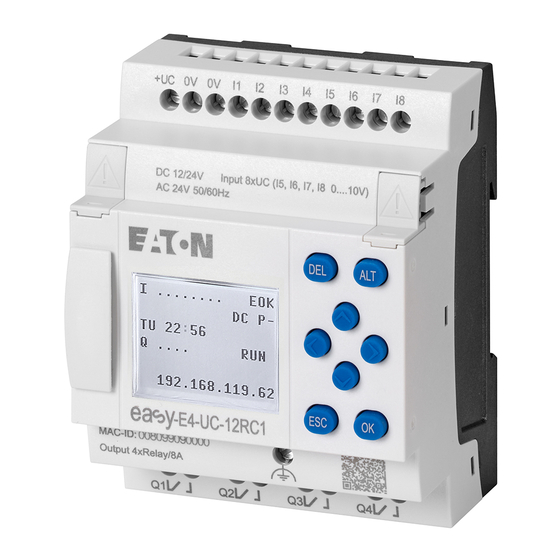
Page 115: Status Display On Control Relay Easye4 With Display And Keypad
3.3 Switch on 3.3.4 Status display on control relay easyE4 with display and keypad After being switched on, the easyE4 base device will start with the status display after the boot logo. The status display has six lines, with each one containing 16 characters. - Page 116 You can use the main menu from the status display in order to access the individual submenus. Press the OK button. The main menu will appear. Tab. 8: Main menu STOP ✓ RUN PARAMETERS SET CLOCK CARD INFORMATION SYSTEM OPTIONS PROGRAM See also → Chapter "3 Operation", page 153 easyE4 02/24 MN050009EN Eaton.com...
-
Page 117: Commissioning The Ethernet Network
Install the Ethernet network as required by your network architecture (switch, router, firewall, VPN, etc.) If you want to run the easyE4 with other devices on the Ethernet network and com- municate through the Internet, you will need to incorporate network security meas- ures outside of the easyE4. -
Page 118: Remote Operation
3. Commissioning 3.3 Switch on 3.3.6 Remote operation If you want to put the easyE4 device into operation without being present at the machine or system, make sure that you always know what exactly will happen when you do so. -
Page 119: Overview Of Switch-On Behavior
As soon as the easyE4 device starts, the options will be read. The easyE4 basic device will check whether a microSD has been inserted and whether there is a starting program on the microSD. The device will then switch to RUN or STOP mode depending on these parameters. - Page 120 RUN start: The device should be able to start without easySoft 8 Allow overwriting via card: If an microSD card with a starting program has been inserted, the device should load from the microSD card ② Options set again, since they could be overwritten by the loaded program easyE4 02/24 MN050009EN Eaton.com...
-
Page 121: Establishing An Ethernet Connection And Transferring A Pro- Gram Or Visualization Project
3.5 Establishing an Ethernet connection and transferring a program or visualization project 3.5 Establishing an Ethernet connection and transferring a program or visualization pro- ject To enable access to an easyE4 base device or a easyE RTD Advanced visualization device via programming, an Ethernet connection is available. Physical connection Ethernet uses point-to-point connections, meaning that whenever more than two devices are connected, there needs to be a switch with a port for each device. - Page 122 Please note that there are IP addresses that are not allowed to be used, as they are reserved for special purposes (e.g., broadcast and loopback IP addresses). Additional information can be found in the Internet Assigned Numbers Authority's (IANA) RFC 6890 - Special-Purpose IP Address Registries. easyE4 02/24 MN050009EN Eaton.com...
- Page 123 The PC must have an Ethernet port that is free and has been configured The Ethernet port on the PC must be on the same subnet as the easyE4 base device and the easyE RTD Advanced visualization device. ...
- Page 124 Search for devices dialog box Fig. 66: Search for devices with an IP address With an existing Ethernet connection, the easyE4 base device and/or the easyE RTD Advanced visualization device is found and gets recorded with its parameters. For each easyE4 base device and/or easyE RTD Advanced visualization device found, use the button to store the IP profile as an IP profile.
- Page 125 Transfer the program and the visualization file Changes in the Interface drop-down menu The IP address of the easyE4 base device is stored under port together with the easyE RTD Advanced visualization device. If a connection to several devices was established before this, correspondingly more entries are available.
- Page 126 easyE4 base device In a download, the program is transferred to the selected easyE4 base device as well as all relevant settings for that device from the project view. easyE RTD Advanced visualization device...
- Page 127 3.5 Establishing an Ethernet connection and transferring a program or visualization project Upload the programs and visualization project files To rebuild a project, you can upload the *.e80 program from the easyE4 base device, the visualization project, and the configuration of the devices back to easySoft 8 by clicking on Device =>...
-
Page 128: Automatic Booting Of The Memory Card
Since the RUN start option is enabled by default, the device will automatically switch to RUN mode. As soon as the easyE4 device switches to RUN mode, it will check whether there is a program in its internal memory. If there are none, the following step will be skipped. -
Page 129: Preparing The Card In The Device For Booting With Easysoft
Start setting up the card by clicking on the Project/Card... menu option. If this is the first time you click on this menu option, make sure to select the drive corresponding to the microSD card. The Card setup dialog box will appear. easyE4 02/24 MN050009EN Eaton.com... - Page 130 3. Commissioning 3.6 Automatic booting of the memory card Transfer program Project/Card... menu option Fig. 70: Offline dialog box for memory card Click the PC -> Card button. easyE4 02/24 MN050009EN Eaton.com...
- Page 131 Select the NET station with the program that you want to transfer to the microSD memory card, e.g., <NET station NT1>. A plausibility check is then run. If the plausibility check is completed successfully, the prompt will appear after the start program. easyE4 02/24 MN050009EN Eaton.com...
- Page 132 BOOT.TXT file. Fig. 71: microSD memory card drive with PROGRAM folder contains BOOT.TXT and compiled test.prg program The card is now prepared with all the prerequisites for booting. You can now use automatic booting for the card. easyE4 02/24 MN050009EN Eaton.com...
-
Page 133: Preparing The Card In The Easye4 Device For Booting With Easysoft
3. Commissioning 3.6 Automatic booting of the memory card 3.6.2 Preparing the card in the easyE4 device for booting with easySoft 8 Prerequisites Licensed easySoft 8 version on the PC Insert the card into the device while the latter is de-energized. - Page 134 3. Commissioning 3.6 Automatic booting of the memory card Project/Card... menu option Fig. 72: Offline dialog box for memory card easyE4 02/24 MN050009EN Eaton.com...
- Page 135 Select the NET station with the program that you want to transfer to the microSD memory card, e.g., <NET station NT1>. A plausibility check will then be run – please refer to → "Plausibility check", page 608. If this plausibility check is completed successfully, the following prompt will appear. easyE4 02/24 MN050009EN Eaton.com...
- Page 136 BOOT.TXT file. Fig. 73: microSD memory card drive with PROGRAM folder contains BOOT.TXT and compiled test.prg program The card is now prepared with all the prerequisites for booting. You can now use automatic booting for the card. easyE4 02/24 MN050009EN Eaton.com...
-
Page 137: Preparing The Card For Booting On The Easye4 Device Itself
The microSD memory card must contain at least one compiled PRG program. The easyE4 device must be in STOP mode before it can be configured. If it is not, the device will point this out. Insert the memory card while the device is de-energized. - Page 138 3. Commissioning 3.6 Automatic booting of the memory card Switch off the power supply. The card is now prepared with all the prerequisites for booting. You can now use automatic booting for the card. easyE4 02/24 MN050009EN Eaton.com...
-
Page 139: Reset With Memory Card - Reset Device To Its Delivery Condition
Insert the microSD memory card. Switch on the easyE4 base device. Now turn off the easyE4 base device and remove the microSD memory card. The easyE4 base device will be reset. The program, password, and all settings will be deleted, and the network interface will work with AUTO-IP. -
Page 140: Updating Firmware
V2. They perform much better than the previous generation because they have a bigger program memory and can communicate faster. The easyE4 base devices as of this version deliver a TLS device certificate that is based on the easyE4 root cer- tificate. -
Page 141: Firmware Update Base Device
8go to the Communication view/HW info tab. In the case of easyE4 base devices with a display, the firmware version can be seen in the Information\System device menu → Section "Information menu", page 165 If there is a program on the base device, the program will be left unchanged when the firmware is updated. - Page 142 Bootloader version 1.01: The configuration in the “e4update.ini” file will be read in the easyE4 bootloader and a compatibility check will be run. An update will not be carried out if the firmware on the device and the firmware on the card match.
- Page 143 Update of base device from generation 08 The firmware update for easyE4 base devices EASY-E4-...-12...C1(P) from generation 08 can be booted from the device menu and also from the "e4settings.ini" con- figuration file on the microSD memory card.
-
Page 144: Updating The Firmware On Expansion Devices
147. 3.8.2 Updating the firmware on expansion devices An expansion device update must run via the device menu of a easyE4 base device. Expansion devices belonging to the first easyE4 generation (with firmware version 1.00) cannot be updated, as these devices do not have a bootloader physically. To find out which firmware version is found on the device, check the Communication view/HW Info tab during online communication. - Page 145 3. Commissioning 3.8 Updating firmware To update the firmware, the easyE4 expansion device must be connected to the base device with the plug connector. The number of the easyE4 expansion is determined based on the position after the base devices in the assembly block, starting with 1 from the left. The maximum num- ber 11 can be assigned to an expansion in the block.
-
Page 146: Updating The Firmware On Easy Communication Modules
Tab. 16: System option- s\Update UPDATE BASE DEVICE COM MODULE ← EXTENSION → Select the number of the easyE4 expansion in the block; 1 to 11 are possible. Tab. 17: System option- s\Update\Expansion EXTENSION <1-11> UPDATE <Filename on SD> 磣£¡¡¡¡¡¡¡¡££££££Ç... - Page 147 To update an easy communication module using a base device with a display, follow the steps below: Go to the main menu. Open the SYSTEM OPTIONEN\UPDATE\KOMM.-MODUL menu path. Tab. 18: System option- s\Update UPDATE BASE DEVICE COM MODULE ← EXTENSION → easyE4 02/24 MN050009EN Eaton.com...
- Page 148 8. To do this, go to the Communication view and connect to your easyE4 block. In the workspace Configuration, the FW version is displayed in the HW info. easyE4 02/24 MN050009EN Eaton.com...
-
Page 149: Functions Of The Microsd Memory Card
3.9 Functions of the microSD memory card easyE4 base devices can be used with a microSD memory card. The easyE4 device supports microSD memory cards with a capacity of 128 MB to 32 GB (SD and SDHC, FAT12/16/32, Class 2 or 4 ). -
Page 150: Setting A Splash Screen For The Easy-E4
PC Fig. 76: Storing the boot.bmp file As soon as the easyE4 device is switched on, the boot.bmp will be shown as a splash screen for the defined duration. In order for the splash screen to keep working, the microSD memory card must remain in the device. -
Page 151: Set System Parameters Using A Memory Card - E4Settings.ini
To transfer the parameters of the "e4settings.ini" file to the base device, proceed as follows: Switch off the easyE4 base device. Plug the microSD memory card with the "e4settings.ini" file into the microSD card holder, then slide the holder into the device. - Page 152 Brightness1 Display brightness during operation on the device, see → Section "Display", page 621 Default value: 100 Brightness2 Brightness for sleep mode Default value: 50 Value: 0 will cause the display to be switched off in sleep mode easyE4 02/24 MN050009EN Eaton.com...
- Page 153 Timeout Brightness - Timeout for brightness changeover Indication of time in seconds when the display changes to rest mode if no operation takes place on the easyE4 device. The changeover time between this display brightness 1 and 2 must be indicated in seconds in accordance with the following table.
- Page 154 16 predefined color combinations. The relevant color settings here are those for remote operation of the easyE4, e.g. on the easyE RTD, in the easySoft 8 or the web server.
- Page 155 To learn which firmware updates match which hardware generation, see → Section "Updating firm- ware", page 136 "e4settings.ini" example for data content from generation 08 See also → "Overview of switch-on behavior", page 115 → "System settings", page 619 easyE4 02/24 MN050009EN Eaton.com...
- Page 156 3. Commissioning 3.11 Set system parameters using a memory card - e4settings.ini easyE4 02/24 MN050009EN Eaton.com...
-
Page 157: Operation
LEDs' flashing patterns. → Section "Startup behavior of easyE4 control relay with LED indicators", page 106 4.1 Base device with display and buttons ... -
Page 158: Display Color Backlight
The display's settings can be configured on the easyE4 device in the SYSTEM OPTIONS\SYSTEM\DISPLAY menu, → Section "Display", page 621 4.1.2 Keyboard... -
Page 159: Selecting Menus And Entering Values
To confirm a selection, press OK. to open the corresponding menu path. If necessary, use the cursor buttons while in a line to toggle between the right and left display areas. If this option is available, the character will appear. ó easyE4 02/24 MN050009EN Eaton.com... -
Page 160: Cursor Display
4. Operation 4.1 Base device with display and buttons 4.1.4 Cursor display The cursor buttons in the easyE4 program perform three functions: Move Enter Connect The current mode is indicated by the appearance of the flashing cursor. -
Page 161: Operating Modes Of The Easye4
The process image of the outputs is transferred to the physical outputs. The easyE4 devices with a display do not start with RUN mode if you deactivate the RUN MODE startup behavior. easyE4 devices with LED indicators have a different startup behavior. On them, the RUN START and CARD START functions will be enabled automatically, as manually starting the device is not possible. - Page 162 4. Operation 4.2 Operating modes of the easyE4 The main menu on the easyE4 display is used to switch between operating modes, i.e., from RUN to STOP and vice versa,→ Section "STOP RUN operating mode menu", page 161 If a program has not been stored on the easyE4, it will not be possible to switch to RUN mode.
-
Page 163: Operation Of The Menu Selection And Value Entry
Undo setting from last OK, current display, leave menu Change contact / relay. Insert new; save settings P1 input when used as P button P2 input when used as P button P3 input when used as P button P4 input when used as P button easyE4 02/24 MN050009EN Eaton.com... -
Page 164: Selecting A Device Menu
Tab. 24: Main menu STOP ✓ RUN PARAMETERS SET CLOCK CARD INFORMATION SYSTEM OPTIONS PROGRAM A horizontal scroll bar indicates that other selection options are available. You may be able to reach them using the cursor keys easyE4 02/24 MN050009EN Eaton.com... -
Page 165: Overview Of The Menus On The Device
4.4.2 STOP RUN operating mode menu This submenu can be used to switch between operating modes. Tab. 27: STOP Tab. 28: RUN STOP ✓ RUN STOP? RUN? STOP RUN ✓ See also → Section "Operating modes of the easyE4", page 157 easyE4 02/24 MN050009EN Eaton.com... -
Page 166: Parameter Menu
Pressing the OK button will show the parameters for the individual function blocks in an additional submenu that can be used to modify these parameters with the cursor buttons. Tab. 32: Timer module example T 01 Ü >I1 >I2 QV> easyE4 02/24 MN050009EN Eaton.com... -
Page 167: Set Clock Menu
4.4 Overview of the menus on the device 4.4.4 Set clock menu This submenu can be used to set the date and time, select the display format for the date, and adjust the daylight saving time and radio clock settings on the easyE4 device. ... -
Page 168: Card Menu
See also → Section "Functions of the microSD memory card", page 145 → Section "Transferring programs from and to a microSD memory card", page → Section "Configuring the microSD card and device ID", page 643 easyE4 02/24 MN050009EN Eaton.com... -
Page 169: Information Menu
4. Operation 4.4 Overview of the menus on the device 4.4.6 Information menu Shows the current status of the easyE4 device. Opens additional menus, The submenu is only provided in English Tab. 45: Main menu Tab. 46: Information Information\Actual Config STOP ✓... -
Page 170: System Options Menu
ROMÂNĀ MAGYAR SRPSKI HRVATSKI SLOVENŠČINA Tab. 52: System option- s\Delete progr. DELETE PROGRAM? Deletes the program in the easyE4 device Tab. 53: System options\Net NET-GROUP: The submenu is only NET-ID: BUSDELAY: provided in English REMOTE RUN easyE4 02/24 MN050009EN Eaton.com... - Page 171 → Section "Setting up a web server", page 713 → Section "Modbus TCP", page 775 → Section "Setting up the e-mail function", page 740 → Section "Convenient visualization for easyE4", page 801 → Section "Functions of the microSD memory card", page 145 easyE4 02/24 MN050009EN Eaton.com...
-
Page 172: Program Menu
4.4 Overview of the menus on the device 4.4.8 Program menu This menu will only be available if the easyE4 is configured with its fact- ory settings and/or when a program created with the EDP programming language has been stored on the easyE4 device. - Page 173 CANCEL, SEARCH, GO TO, and SAVE options by scrolling through them with the cursor buttons in the bottommost line. After editing the function blocks, the CANCEL and SAVE options will be available. Tab. 60: Programs\Circuit dia- Tab. 61: Programs\Function gram blocks SAVEÓ ABORTÓ easyE4 02/24 MN050009EN Eaton.com...
-
Page 174: Your First Edp Program
This should enable you to become familiar with all the relevant rules and use an easyE4 device for your own projects in no time. Just like with con- ventional wiring, you will be using contacts and relays in the program. This means that the easyE4 device makes it possible to eliminate the use of these components in a variety of ways, including the use of function blocks. - Page 175 The cursor flashes at the top left, which is where you will start to wire your circuit diagram. Circuit diagram display Fig. 80: Empty circuit diagram The last line shows the cursor's position: L: = Rung (Line). C: = Contact or coil field (Column). Amount of free memory in bytes. easyE4 02/24 MN050009EN Eaton.com...
-
Page 176: Draw A Wiring Diagram
The easyE4 automatically connects the contact to the power supply. The following example is provided for a lighting control. The easyE4 device takes on the wiring and the tasks of the circuit shown below. easyE4 02/24 MN050009EN Eaton.com... - Page 177 Q001 From the first contact to the output coil With easyE4 devices wire from the input to the output. The first input contact is I001 Press the OK button. easyE4 will insert the first contact, , at the cursor position.
- Page 178 When you move the arrow onto a contact or relay coil, it changes back to the cursor and can be reactivated if required. The easyE4 device automatically connects adjacent contacts up to the coil. Press the ALT to wire the cursor from through to the coil field.
- Page 179 Fig. 85: SAVE menu option in the status line Press the OK button to confirm. The circuit diagram is stored. Press the ESC button twice to return to the main menu. You can test the circuit diagram if the S1 and S2 buttons are connected. easyE4 02/24 MN050009EN Eaton.com...
-
Page 180: Testing The Circuit Diagram
Go back to the main menu. Select the STOP RUN menu option. The current operating mode is indicated on the display of the easyE4 device by a tick at RUN or STOP stop. Pressing the OK button enables you to toggle between the modes. -
Page 181: Control Options In Run Mode
Test using the power flow display Change to the circuit diagram display and press pushbutton S1. The relay picks up and the easyE4 displays the power flow with a double line. I001===I002===========Ä Q001 Fig. 86: Power flow display 1 Power flow display: Inputs I001 and I002 are closed, relay Q1 has picked up Press pushbutton S2, that has been connected as a break contact. - Page 182 Press the ALT button. The zoom function will be turned off and the display will switch to the display status with contact and/or coil designations. Power flow display: Input I01 is closed, input I02 is open, relay Q1 has dropped out. easyE4 02/24 MN050009EN Eaton.com...
-
Page 183: Delete Program
NET parameterization. Proceed as follows to delete the program in the easyE4 device: easyE4 must be in STOP mode in order to extend, delete or modify the circuit dia- gram. Switch the easyE4 device to STOP mode. -
Page 184: Transfer Program To The Easye4 Device
4. Operation 4.6 Transfer program to the easyE4 device 4.6 Transfer program to the easyE4 device There are two options for directly transferring a finished .e80 program to an easyE4 device. With a microSD memory card With a direct Ethernet connection between the PC and easyE4 4.6.1 Transfer with a microSD memory card... - Page 185 4. Operation 4.6 Transfer program to the easyE4 device Click on the Project\ Card... menu option. View Project easySoft 8 Fig. 90: Sample program open In the Card setup dialog box that appears, click on the icon to select the card root directory that easySoft 8 needs in order to create the LOGS and PROGRAM folders.
- Page 186 4. Operation 4.6 Transfer program to the easyE4 device The Card setup dialog box will appear. easySoft 8 Project View\Project\Card... Fig. 91: Card setup dialog box You can use the Card section to specify the storage location, i.e., the drive, where the microSD memory card is located.
- Page 187 4. Operation 4.6 Transfer program to the easyE4 device Use this dialog box to enter the name that the program should have on the easyE4 device. Please make sure that this name does not have more than 14 characters (only letters and numbers are permitted).
- Page 188 Close the window Remove the microSD memory card from the drive. Insert the microSD memory card into the slot on the easyE4 base device. → Section "Inserting a microSD card", page 88 The easyE4 device will be ready for operation.
-
Page 189: Establishing An Ethernet Connection
This capability can be in the form of a local Ethernet port on the PC or a standard adapter (e.g., USB-to-Ethernet adapter). The PC's and the easyE4 base device's IP addresses must fall within the same range, i.e., the addresses' first two or three numbers must be the same, while the last num- ber must be different and not equal to 0. - Page 190 Example using Windows Fig. 94: Ethernet connection on PC You can now connect to your easySoft 8 device with the easyE4 programming soft- ware. See also → Section "Establishing an Ethernet connection and transferring a program or visualization project", page 117...
-
Page 191: Programming On The Device
Programs/Circuit Diagram Fig. 95: Circuit diagram display In the easyE4 circuit diagram, contacts and coils of relays are connected up from left to right - from the contact to the coil. The circuit diagram is created on a hidden wiring grid containing contact fields, coil fields and rungs. - Page 192 There are 256 rungs available in the circuit diagram, for wiring contacts and coils. For greater legibility the circuit diagram display of the easyE4 device shows two con- tacts or one contact plus coil in a row on each rung. A total of 16 characters per cir- cuit connection and five circuit connections plus the status line can be displayed simultaneously.
-
Page 193: Circuit Diagram Elements
5.3 Circuit diagram elements 5.3 Circuit diagram elements A circuit diagram is a series of commands that the easyE4 device processes cyc- lically in RUN operating mode. Coils and contacts are interconnected in the circuit diagram. In RUN mode, a coil is switched on or off depending on the power flow and coil function set. -
Page 194: Contacts
N/O contacts are set to 1 when they are closed and 0 when they are opened. In the easyE4 circuit diagram you can wire contacts as make or break contacts. N/C contacts are indicated with a horizontal line above the operand concerned. -
Page 195: Coils
(0) state according to these results. The options for setting output and marker relays are listed with the description of each coil function. A easyE4 device is provided with different types of relays and function blocks which can be wired in a circuit diagram via their coils (inputs). - Page 196 Fig. 97: Impulse relay signal diagram A coil is automatically switched off in the event of a power failure and in STOP mode. Exception: retentive coils retain the 1 state. See also → Section "Retention function", page 636 easyE4 02/24 MN050009EN Eaton.com...
- Page 197 Reset coil in the example above.) I 05---------------S Q 01 I 10---------------R Q 01 Fig. 99: Simultaneous triggering of Q 01 The above example shows the Reset coil with priority when the Set and Reset coil are triggered at the same time. easyE4 02/24 MN050009EN Eaton.com...
- Page 198 This function is used if the coil is only meant to switch on a rising edge. When the coil status changes from 0 to 1, the coil switches its make contacts to 1 for one cycle. Fig. 101: Signal diagram of cycle pulse with rising edge easyE4 02/24 MN050009EN Eaton.com...
- Page 199 1 to 0, the coil switches its make contacts to 1 for one cycle. Fig. 102: Signal diagram of cycle pulse with negative edge A set coil is automatically switched off in the event of a power failure and in STOP mode. Retentive coils keep their logic state. easyE4 02/24 MN050009EN Eaton.com...
-
Page 200: Working With Contacts And Coils
5.4 Working with contacts and coils 5.4 Working with contacts and coils Switches, pushbuttons and relays from a conventional hardwired circuit diagram are wired in the easyE4 circuit diagram via input contacts and relay coils. Hardwired Wired with an easyE4 device easyE4 connection ... -
Page 201: Entering And Modifying Contacts
5.4.1 Entering and modifying contacts Fig. 104: Contact legend You choose an input contact in the easyE4 device by means of the contact name and the contact number. Example: Base device input contact or function block contact consists of the abbre- viated function block name, the number, and the contact function. -
Page 202: Changing An N/O Contact To An N/C Contact
Bear in mind that the active state of an N/C contact is 0. The 0 state of a contact may, however, be present if the station is missing or is operating incorrectly. The use of an N/C contact in the circuit diagram without evaluating the diagnostics bit may cause incorrect interpretations. easyE4 02/24 MN050009EN Eaton.com... -
Page 203: Entering And Modifying Coils
(a selected position is shown in light grey in the following figure). Use the cursor buttons to change the value at the position. The easyE4 device will exit input mode as soon as you exit a contact or coil field with cursor buttons or the OK button. easyE4 02/24 MN050009EN Eaton.com... -
Page 204: Deleting Contacts And Coils
Q 001 to S Q 008 I 02 5.4.4 Deleting contacts and coils Use the buttons to move the cursor to a free contact or coil field. Press the DEL pushbutton. The contact or the coil will be deleted, together with any connections. easyE4 02/24 MN050009EN Eaton.com... -
Page 205: Creating And Modifying Connections
Press the ALT button to leave Connect mode. The easyE4 device closes the mode automatically as soon as you have moved the arrow to an occupied contact or coil field. In a rung, the easyE4 device connects contacts and the con- nection to the relay coil automatically if no empty fields are between them. -
Page 206: Deleting Connections
The circuit diagram display shows three of the 256 rungs at the same time. Rungs out- side of the display, including empty rungs, are scrolled by easyE4 automatically in the circuit diagram display if you move the cursor beyond the top or bottom of the dis- play. -
Page 207: Got To A Rung
SAVE menu. Press the OK button. The entire program, circuit diagram and function blocks will be saved. After saving, you will be returned to the previous menu from which you have opened the circuit diagram. easyE4 02/24 MN050009EN Eaton.com... -
Page 208: Exiting The Circuit Diagram Without Saving
If the required contact or coil is located above the point of calling, start the search at the beginning of the circuit diagram. If the search is successful, you will automatically reach the required contact or coil field in the circuit diagram. easyE4 02/24 MN050009EN Eaton.com... -
Page 209: Switching With The Cursor Buttons
5.4 Working with contacts and coils 5.4.13 Switching with the cursor buttons You can use the four cursor buttons on the easyE4 device as hardwired inputs in the circuit diagram. The P buttons can be used for testing circuits or for manual operation. The button function is a useful addition for service and commissioning tasks. -
Page 210: Checking The Circuit Diagram
5.4.14 Checking the circuit diagram The easyE4 device features an integrated power flow display with which you can fol- low the switching states of contacts, relay and function block coils during operation. The circuit diagram display performs two functions depending on the mode: ... -
Page 211: Jumps
The use of jumps in the function block diagram is explained in → "LB - Jump label", page 521 and → "JC - Conditional jump", page 516. The easyE4 device allows the use of up to 32 jumps. Circuit diagram elements for jumps in the circuit diagram Contact (N/O1) ... - Page 212 5.4 Working with contacts and coils Backward jumps cannot be executed due to the way in which easyE4 works. If the jump label does not come after the jump coil, the jump will be made to the end of the circuit diagram.
-
Page 213: Wiring Net Operands In The Circuit Diagram
This mode is displayed by a flashing operand. Use the cursor button to move the cursor to the position to the left of the oper- ú and. A flashing zero appears as the initial value. easyE4 02/24 MN050009EN Eaton.com... - Page 214 Put (PT) and Get (GT) are used in order to exchange double word operands via the NET. For more information on the manufacturer function blocks: → Section "Working with function blocks", page 217 → Section "Function blocks", page 241 easyE4 02/24 MN050009EN Eaton.com...
- Page 215 2 slave 1 slave Destination Source The relevant circuit diagram is as follows: On NET station 1 the status of P1 is associated via RN01 as a count pulse for the counter relay C01. easyE4 02/24 MN050009EN Eaton.com...
- Page 216 More information about the function blocks: → Section "Function blocks", page 241 NET marker N.., nB.., nW.., nD... Every station that the NET marker describes can read any of the other stations. Fig. 117: 1 slave Fig. 118: 2 slaves easyE4 02/24 MN050009EN Eaton.com...
-
Page 217: Transferring Programs From And To A Microsd Memory Card
Programs are normally transferred from easySoft 8 to the device so that they can be run on the device. If the easyE4 base device has a microSD memory card, the program can also be stored on this memory card, → Section "Automatic booting of the memory card", page You can store multiple programs on a single memory card. -
Page 218: Configuration On A Base Device With A Display
Data can be written to a binary file by using the DL (Data Logger) manufacturer function block. These logs can be managed here. MANAGE CARD Used to format and eject the card INFORMATION Provides information on the card size and the amount of free space left easyE4 02/24 MN050009EN Eaton.com... -
Page 219: Program Submenu
Requirement: The following option must be enabled when creating the program in easySoft: Allow overwriting via card You can use this submenu to manage the programs on the easyE4. The program transfer menu offers the following options: Tab. 79: Card\Program SET BOOT PROG. - Page 220 Overwrites the selected program with the program from the easyE4 SAVE AS Makes it possible to save the current program on the easyE4 under a new name See also → Section "Functions of the microSD memory card", page 145...
-
Page 221: Working With Function Blocks
Or vice versa: you create the function block in the function block editor, define the parameters and use it then in the circuit diagram. With easyE4 devices you can insert up to 255 manufacturer function blocks in the function block list. - Page 222 (constants). You must at least confirm the +/- character with the OK button. Parameter sets can only be enabled or protected via the FUNCTION RELAYS menu, or via the circuit diagram with the “+” enable and with “–” inhibit parameter set characters. easyE4 02/24 MN050009EN Eaton.com...
-
Page 223: Function Block List
Press the ESC button in order to save the circuit diagram with the newly added function block. Answer the subsequent SAVE prompt with the OK button. The circuit diagram is saved and the easyE4 device changes to the next higher menu level. 5.6.2 Function block list The function block list can be used to access the function block editor. -
Page 224: Configuring Parameters In The Function Block Editor
Parameter display (+ appears/ – does not appear) Block name Basic parameters Function block inputs Variable, operand for inputs Function block out- puts Variable, operand for outputs Fig. 120: Manufacturer function block display in the function block editor easyE4 02/24 MN050009EN Eaton.com... - Page 225 If, for example, the T timing relay function block is driven with a negative time ref- erence, it will no longer switch as expected. You should therefore take care to exclude such situations, as the easyE4 device can- not foresee these when the parameters are assigned.
- Page 226 The following operands can be assigned to the output of a QV manufacturer function block: Markers such as MD, MW, MB, or the analog output QA. Deleting operands at function block inputs/outputs Position the cursor on the required operand. Press the DEL pushbutton. The operand is deleted. easyE4 02/24 MN050009EN Eaton.com...
-
Page 227: Parameters Menu
Move from the Status display to the Parameters display by pressing OK -> PARAMETERS. Follow the operating steps described in → Section "Assigning operands at a manufacturer function block's input", page 221 easyE4 02/24 MN050009EN Eaton.com... -
Page 228: Deleting Function Blocks
To remove a function block, you must remove it from the circuit diagram and from the function block list. Requirement: The easyE4 device must be in STOP mode. Switch to the circuit diagram display by selecting Main menu -> PROGRAMS -> CIRCUIT DIAGRAM. - Page 229 32-bit data format is used automatically. This also enables the transfer of neg- ative values. The following applies to RUN mode: A easyE4 device processes the manufacturer function block after a pass through the circuit diagram. This takes the last status of the coils into account.
-
Page 230: Using Operands In A Program
TRUE (1) BYTE/(Byte) Decimal number 0…255 (unsigned) WORD/(Word) Decimal number 0 - 65535 1023 (unsigned) DWORD/(Double Word) Decimal number -2 147 483 648… - 65535 (signed) +2 147 483 647 easyE4 02/24 MN050009EN Eaton.com... -
Page 231: Permissible Operands At A Glance
ID1…ID24 ID25…ID96 LE1…LE3 Local value operands IA1...IA4 IA5...IA48 QA1...QA4 QA5...QA48 MB1…MB512 MW1…MW512 MD1…MD256 N operands bit N1…N512 (EDP: N1…N128) xRN1…xRN32 xSN1…xSN32 N operands value NB1…NB64 NW1…NW32 ND1…ND16 1) base device permanently assigned 2) Not available for visualization elements easyE4 02/24 MN050009EN Eaton.com... -
Page 232: Connection Rules For Operands
Q - Bit output from another FB Assigning operands Value inputs Value outputs Constant Markers: MB, MD, MW Analog inputs IA Analog output QA Numeric output from another QV FB easyE4 02/24 MN050009EN Eaton.com... -
Page 233: Overview Of Operands Numeric Formats
The easyE4 device processes calculations with a signed 31-bit value. The value range is: -2147483648 to +2147483647 With a 31 bit value, the 32nd bit is the sign bit. -
Page 234: Timer Constant
Values that fall outside the set resolution will be rounded down automatically. For instance, entering a value of <9> for a time constant with a time range of S - 000.000 and a resolution of 5 ms will result in the value being rounded down to 5 ms. easyE4 02/24 MN050009EN Eaton.com... - Page 235 Example: For a time range of M:S - 00:00 and a resolution of 1 s, entering <t#5m10s>. Fig. 122: Programming view: Selected timer constant on function block input I1 and unconfirmed value of <t#5m10s> entered with the keyboard easyE4 02/24 MN050009EN Eaton.com...
- Page 236 Fig. 123: Programming view: Selected timer constant on function block input I1 and unconfirmed value of <t#3h25m> entered with the keyboard Negative times are allowed, but only for timer constants connected to the input of AC function blocks. In this case, you can enter values within the following range: - 12h00m to +12h00m. easyE4 02/24 MN050009EN Eaton.com...
- Page 237 62m 00s ✓ 1h 39m 99m 00s ✓ 1h 40m 40m 00s The conversion results in 100 minutes. However, this exceeds the max. time range limit of 99 minutes for the timer constants -> message easyE4 02/24 MN050009EN Eaton.com...
-
Page 238: Organizing Marker Ranges
Boolean states 0 or 1. A marker bit is also called an auxiliary relay. easyE4 devices also manage the marker bits in marker bytes (MB), marker words (MW) and in marker double words (MD). A marker byte consists of 8 marker bits, a marker word of 16 marker bits and a marker double word of 32 marker bits. - Page 239 1. Project/Marker area assignment menu option Fig. 124: Marker range map with write conflict for MW1 The operand table below shows the relationships between marker bits, bytes, words, and double words in a different way. easyE4 02/24 MN050009EN Eaton.com...
-
Page 240: Operand Table
Only double words have a sign bit. The other data formats do not. Example 1: Bit81 is contained in MB11, MW6 and DW3. Example 2: Byte21 is contained in MW11 and DW6 and contains bits Bit161 to Bit168. easyE4 02/24 MN050009EN Eaton.com... - Page 241 5. Programming on the device 5.7 Using operands in a program easyE4 02/24 MN050009EN Eaton.com...
- Page 242 5. Programming on the device 5.7 Using operands in a program easyE4 02/24 MN050009EN Eaton.com...
-
Page 243: Retentive Markers
→ "UF - User function block", page 588 32 marker bits → "IE - Edge-controlled interrupt", page 574 → "IC - Counter-controlled interrupt", page 562 → "IT - Time-controlled interrupt function block", page 580 easyE4 02/24 MN050009EN Eaton.com... - Page 244 MN050009EN Eaton.com...
-
Page 245: Function Blocks
→ page 295 Counter Function Blocks C - Counter relay → page 304 CF - Frequency counter → page 310 CH - High-speed counter → page 316 CI - Incremental counter → page 322 easyE4 02/24 MN050009EN Eaton.com... - Page 246 → page 523 MR - Master Reset → page 534 MU - Acyclical Modbus RTU request → page 538 NC - Numerical converter → page 553 ST - Set cycle time → page 559 easyE4 02/24 MN050009EN Eaton.com...
- Page 247 IT - Time-controlled interrupt function block → page 580 User function block – used to create custom function blocks User function blocks are only available in easySoft 8. UF - User function block → page 588 easyE4 02/24 MN050009EN Eaton.com...
-
Page 248: Manufacturer Function Blocks
6.1.1 Timer modules 6.1.1.1 HW - Weekly timer (Hour Week) easyE4 devices feature a real-time clock with a date and time functionality. When combined with the HW, HY or WT, YT function blocks, this real-time clock makes it possible to implement the functionality of a weekly timer and year time switch. - Page 249 Value outputs MB, MD, MW – Markers NB, NW, ND – NET markers NET station n QA – Analog output I – Value input of a FB Only on projects with ≥ 2 base devices on NET easyE4 02/24 MN050009EN Eaton.com...
- Page 250 Constants can be edited on the + Call enabled device, as can function block para- meters when using the EDP pro- gramming language. Edit interrupt routine Clicking on this button will open the interrupt routine Simulation possible easyE4 02/24 MN050009EN Eaton.com...
- Page 251 Information on the battery back-up time are provided on → Section "Back-up of real- time clock", page 828 After being switched on, the control relay will always update its switch- ing state based on all existing switching time settings and will switch Q1 accordingly. easyE4 02/24 MN050009EN Eaton.com...
- Page 252 The time switch is required to switch from 10:00 to 18:00 from Fridays to Sundays. Fig. 125: Signal diagram The HW time switch must be assigned the following parameters: Fig. 126: Programming view Weekly timer parameters tab easyE4 02/24 MN050009EN Eaton.com...
- Page 253 The time switch is required to switch from Mondays to Fridays between 6:30 and 9:00 and between 17:00 and 22:30. Fig. 127: Signal diagram The HW time switch must be assigned the following parameters: Fig. 128: Programming view Weekly timer parameters tab easyE4 02/24 MN050009EN Eaton.com...
- Page 254 The time switch is required to switch on at 18:00 on Tuesdays and switch off at 6:00 on Saturdays. Fig. 129: Signal diagram The HW time switch must be assigned the following parameters: Fig. 130: Programming view Weekly timer parameters tab easyE4 02/24 MN050009EN Eaton.com...
- Page 255 Q1 to 1. The first off time of a channel switches output Q1 to 0. If the on time and off time are the same, the output Q1 is switched off. The HW time switch must be assigned the following parameters: Fig. 132: Programming view Weekly timer parameters tab Settings Time overlap easyE4 02/24 MN050009EN Eaton.com...
- Page 256 The time switch is to switch for 24 hours. On time at 00:00 on Monday and off time at 00:00 on Tuesday. Fig. 133: Signal diagram The HW time switch must be assigned the following parameters: Fig. 134: Programming view Weekly timer parameters tab - 24 hours setting easyE4 02/24 MN050009EN Eaton.com...
- Page 257 → Section "T - Timing relay", page 272 → Section "WT - Weekly timer (WeekTable)", page 291 → Section "YT - Year time switch (Year Table)", page 284 → Section "AC - Astronomic clock ", page 295 easyE4 02/24 MN050009EN Eaton.com...
-
Page 258: Hy - Year Time Switch (Hora Year)
6.1 Manufacturer function blocks 6.1.1.2 HY - Year time switch (Hora Year) easyE4 devices feature a real-time clock with a date and time functionality. When combined with the HW, HY or WT, YT function blocks, this real-time clock makes it possible to implement the functionality of a weekly timer and year time switch. - Page 259 ON. In the same way, the year time switch switches the contact off with the first detected OFF, irrespective of whether another channel still supplies the ON signal. Please note that the time switches can only be configured up to the year 2099. easyE4 02/24 MN050009EN Eaton.com...
- Page 260 I - Bit input Q - Bit output Q - Bit output of a FB Only on projects with ≥ 2 base devices on NET Function block outputs Description Note (bit) 1: if the on condition is fulfilled. easyE4 02/24 MN050009EN Eaton.com...
- Page 261 EDP pro- gramming language. Simulation possible Parameterization If you select the function block in the easySoft 8 Programming view by clicking on it, a table with the various parameters will appear under the tab. easyE4 02/24 MN050009EN Eaton.com...
- Page 262 The year time switch should switch on at 00:00 on day 01.01.2022 and switch off when the OFF year has elapsed at 00:00 on day 01.01.2031. The parameters are set in one channel. Refer to the → "Example 1: Select year range", page 260 below for this time range. easyE4 02/24 MN050009EN Eaton.com...
- Page 263 Refer to the → "Example 7: Overlapping ranges", page 263 below for these time ranges. In these cases, a time cannot be configured for switching, and switching will always occur for the entire day, from 00:00 to 24:00. This is a set configuration that cannot be modified at runtime. easyE4 02/24 MN050009EN Eaton.com...
- Page 264 The year time switch HY01 should switch on at 1 March , 00:00 h, and remain switched on until 1 November, 00:00 h. The HY year time switch must be assigned the following parameters: Programming view/HY01/Year time switch parameters tab Fig. 138: Entry screen in the programming software easyE4 02/24 MN050009EN Eaton.com...
- Page 265 The year time switch HY01 is required to switch on at 00:00 on day 25.12 of each year and switch off at 00:00 on day 28.12 of each year. The HY year time switch must be assigned the following parameters: Programming view/HY01/Year time switch parameters tab Fig. 140: Entry screen in the programming software easyE4 02/24 MN050009EN Eaton.com...
- Page 266 10 of each year and switch off at 00:00 on day 17 of the month. The HY year time switch must be assigned the following parameters: Programming view/HY01/Year time switch parameters tab Fig. 142: Entry screen in the programming software easyE4 02/24 MN050009EN Eaton.com...
- Page 267 → Section "T - Timing relay", page 272 → Section "WT - Weekly timer (WeekTable)", page 291 → Section "YT - Year time switch (Year Table)", page 284 → Section "AC - Astronomic clock ", page 295 easyE4 02/24 MN050009EN Eaton.com...
-
Page 268: Ot - Operating Hours Counter
6.1 Manufacturer function blocks 6.1.1.3 OT - Operating hours counter General easyE4 base devices provide 4 operating hours counter func- tion blocks, OT01 through OT04. These function blocks output minutes and seconds in addition to hours. A comparison with a reference value that can be entered makes it possible, for instance, to signal when maintenance work is due. - Page 269 You can assign the following operands to the function block inputs that are bit inputs: Operands Bit inputs Constant 0, constant 1 M - Markers RN - Input bit via NET SN - Output bit via NET (send) N - Net marker bit nN - NET marker bit NET station n easyE4 02/24 MN050009EN Eaton.com...
- Page 270 SN - Output bit via NET (send) N – Network marker bit LE – Output backlight Q – Bit output I – Bit input of a FB Only on projects with ≥ 2 base devices on NET easyE4 02/24 MN050009EN Eaton.com...
- Page 271 6. Function blocks 6.1 Manufacturer function blocks easyE4 02/24 MN050009EN Eaton.com...
- Page 272 → Section "RC - Real-time clock", page 269 → Section "T - Timing relay", page 272 → Section "WT - Weekly timer (WeekTable)", page 291 → Section "YT - Year time switch (Year Table)", page 284 easyE4 02/24 MN050009EN Eaton.com...
-
Page 273: Rc - Real-Time Clock
6.1.1.4 RC - Real-time clock General easyE4 base devices provide exactly one real-time clock RC01. This function block can be used to read the date and time value of the device's real-time clock. This value is output in seven indi- vidual parameters than can each be processed further indi- vidually. - Page 274 Value outputs MB, MD, MW – Markers NB, NW, ND – NET markers NET station n QA – Analog output I – Value input of a FB Only on projects with ≥ 2 base devices on NET easyE4 02/24 MN050009EN Eaton.com...
- Page 275 → Section "OT - Operating hours counter ", page 264 → Section "T - Timing relay", page 272 → Section "WT - Weekly timer (WeekTable)", page 291 → Section "YT - Year time switch (Year Table)", page 284 easyE4 02/24 MN050009EN Eaton.com...
-
Page 276: T - Timing Relay
6.1.1.5 T - Timing relay General easyE4 base devices provide 32 timing relays (timer) T01…T32. You can use a time relay to delay the switching duration and the ON and OFF times of a switch contact. The times can be set from a range of 5 ms to 99 h 59 min. - Page 277 NET markers NET station n IA - Analog input QA - Analog output QV - QV - Numeric output of a FB Only on function blocks T, AC Only on projects with ≥ 2 base devices on NET easyE4 02/24 MN050009EN Eaton.com...
- Page 278 Operand value 45507 -> 45,510 s. Examples of time range M:S: Operand value 5999 -> Time value is 99 min, 59 s. Example of time range H:M: Operand value 5999 -> Time value is 99 h, 59 min. easyE4 02/24 MN050009EN Eaton.com...
- Page 279 Function block outputs Description Note (bit) Switching contact (DWord) Elapsed actual time in RUN mode Integer value range: 0 to max. 99990 in time range: seconds; milliseconds; hours depending on configured time range. easyE4 02/24 MN050009EN Eaton.com...
- Page 280 01:40 01:40 00:300 05:00 05:00 00.500 08:20 08:20 4095 (Maximum) 04:095 68:15 68:15 M:S time base Rule: Time setpoint = Variable value/60 Integer Number of minutes, Residual Number of seconds easyE4 02/24 MN050009EN Eaton.com...
- Page 281 Setpoint time Range A: The time runs down from the SET time value. Range B: The time does not elapse because the trigger coil drops out prematurely. Range C: The Stop coil stops the time from elapsing. easyE4 02/24 MN050009EN Eaton.com...
- Page 282 The contact of the timing relay switches randomly within the setpoint value range. Retriggering When the time is running and the trigger coil is reactivated or deactivated, the actual value is reset to zero. The set time of the timing relay is timed out once more. easyE4 02/24 MN050009EN Eaton.com...
- Page 283 Range F: The trigger coil drops out twice. The actual time t1 is cleared and the set time ts elapses com- pletely (retriggerable switch function). How the timing relay works with the on/off-delayed operating mode with and without random times Time value I1: on-delay time Time value I2: Off-delay time Random switching easyE4 02/24 MN050009EN Eaton.com...
- Page 284 Range A: The relay processes the two times without any interruption. Range B: The trigger coil drops out before the on-delay is reached. Range C: The stop coil stops the timeout of the on-delay. Range D: The stop coil has no effect in this range. easyE4 02/24 MN050009EN Eaton.com...
- Page 285 • Range D: The reset coil resets the timing relay. Range E: The reset coil resets the timing relay. The trigger coil is still energized after the reset coil is dis- connected, whilst the delay time runs down.. easyE4 02/24 MN050009EN Eaton.com...
- Page 286 Example: You have configured the time range M: S and the counter actual value is 31333. The device limits the setpoint to 5999 min. Note the relationship described below between the permissible analog value and the timing relay setpoint. Output of a timing relay (e.g. T4QV). easyE4 02/24 MN050009EN Eaton.com...
- Page 287 → Section "OT - Operating hours counter ", page 264 → Section "RC - Real-time clock", page 269 → Section "WT - Weekly timer (WeekTable)", page 291 → Section "YT - Year time switch (Year Table)", page 284 easyE4 02/24 MN050009EN Eaton.com...
-
Page 288: Yt - Year Time Switch (Year Table)
6.1 Manufacturer function blocks 6.1.1.6 YT - Year time switch (Year Table) easyE4 devices feature a real-time clock with a date and time functionality. When combined with the HW, HY or WT, YT function blocks, this real-time clock makes it possible to implement the functionality of a weekly timer and year time switch. - Page 289 NET station n ID: Diagnostic alarm LE - Output backlight P device buttons I - Bit input Q - Bit output Q - Bit output of a FB Only on projects with ≥ 2 base devices on NET easyE4 02/24 MN050009EN Eaton.com...
- Page 290 (all eight channels will act on output Q1). There is an ON time and an OFF time that are accurate to the day for each chan- nel. Parameter display Constants can be edited on the easyE4 02/24 MN050009EN Eaton.com...
- Page 291 In these cases, a time cannot be configured for switching, and switching will always occur for the entire day, from 00:00 to 24:00. This is a set configuration that cannot be modified at runtime. This example uses all four available modes. easyE4 02/24 MN050009EN Eaton.com...
- Page 292 Example 3: Select “public holidays" Year time switch YT01 should switch on on 12/05 of every year at 00:00 and remain switched on until 12/28 of every year at 00:00. The YT year time switch must be assigned the following parameters: easyE4 02/24 MN050009EN Eaton.com...
- Page 293 If there are overlapping switching intervals, the function block may switch off output Q1 earlier if the switching-off moment for a different channel takes place before the configured OFF date. In the following example, Q1 is switched on every first Monday easyE4 02/24 MN050009EN Eaton.com...
- Page 294 → Section "RC - Real-time clock", page 269 → Section "T - Timing relay", page 272 → Section "WT - Weekly timer (WeekTable)", page 291 → Section "AC - Astronomic clock ", page 295 easyE4 02/24 MN050009EN Eaton.com...
-
Page 295: Wt - Weekly Timer (Weektable)
6.1 Manufacturer function blocks 6.1.1.7 WT - Weekly timer (WeekTable) easyE4 devices feature a real-time clock with a date and time functionality. When combined with the HW, HY or WT, YT function blocks, this real-time clock makes it possible to implement the functionality of a weekly timer and year time switch. - Page 296 Value outputs MB, MD, MW – Markers NB, NW, ND – NET markers NET station n QA – Analog output I – Value input of a FB Only on projects with ≥ 2 base devices on NET easyE4 02/24 MN050009EN Eaton.com...
- Page 297 Parameterization If you select the function block in the easySoft 8 Programming view by clicking on it, a table with the various parameters will appear under the tab. Fig. 161: Weekly timer (new) parameters tab with an example easyE4 02/24 MN050009EN Eaton.com...
- Page 298 → Section "RC - Real-time clock", page 269 → Section "T - Timing relay", page 272 → Section "YT - Year time switch (Year Table)", page 284 → Section "AC - Astronomic clock ", page 295 easyE4 02/24 MN050009EN Eaton.com...
-
Page 299: Ac - Astronomic Clock
1.10 or higher for the project. General easyE4 base devices provide 32 astronomic clock function blocks, AC01 through AC32. Output Q1 in these function blocks is switched on during the time between sunrise and sunset. - Page 300 NET station n ID: Diagnostic alarm LE - Output backlight P device buttons I - Bit input Q - Bit output Q - Bit output of a FB Only on projects with ≥ 2 base devices on NET easyE4 02/24 MN050009EN Eaton.com...
- Page 301 You can assign the following operands to the function block outputs that are bit out- puts: Assigning operands Bit outputs M - Markers SN – Output bit via NET (send) SN - Output bit via NET (send) N – Network marker bit LE – Output backlight easyE4 02/24 MN050009EN Eaton.com...
- Page 302 0 or 1 depending on the function block. Parameter display Constants can be edited on the + Call enabled device, as can function block para- meters when using the EDP pro- gramming language. Simulation possible easyE4 02/24 MN050009EN Eaton.com...
- Page 303 Fig. 162: Sunrise and sunset in Bonn Drevja in Norway The following is the geodata for the Drevja location in Norway: Latitude: 65.9780775 Longitude: 13.2348074 The sun does not set during the summer months (day 165 to 180). easyE4 02/24 MN050009EN Eaton.com...
- Page 304 Latitude: 4.0047314 Longitude: 9.7329299 The sunrise and sunset times remain the same throughout the whole year with little variation. Fig. 164: Offset; O1=-2; O2=2; Q1=1 will switch on 2 hours before sunrise and off 2 hours after sunset easyE4 02/24 MN050009EN Eaton.com...
- Page 305 Fig. 166: Offset; O1=1; O2= -1; Q1 will switch on 1 hour after sunrise and off 1 hour before sunset Fig. 167: Offset; O1=-2; O2=2; Q1=1 will switch on 2 hours before sunrise and off 2 hours after sunset easyE4 02/24 MN050009EN Eaton.com...
- Page 306 Longitude: 0 Offset O1 = 5 Offset O2 = -7 In the winter months, the switch-off time is before the switch-on time. This will cause function block output Q1 to always remain off during these months. easyE4 02/24 MN050009EN Eaton.com...
- Page 307 → Section "RC - Real-time clock", page 269 → Section "T - Timing relay", page 272 → Section "WT - Weekly timer (WeekTable)", page 291 → Section "YT - Year time switch (Year Table)", page 284 easyE4 02/24 MN050009EN Eaton.com...
-
Page 308: Counter Function Blocks
You can set a lower and higher limit setpoint as comparison values for the counter relay function block, as well as a start value. General easyE4 base devices provide 32 counter relays, C01 through C32. Each counter relay can count up and down and func- tions as a double word counter. - Page 309 You can assign the following operands to the function block inputs that are bit inputs: Operands Bit inputs Constant 0, constant 1 M - Markers RN - Input bit via NET SN - Output bit via NET (send) easyE4 02/24 MN050009EN Eaton.com...
- Page 310 Only on projects with ≥ 2 base devices on NET You can assign the following operands to the function block outputs that are bit out- puts: Assigning operands Bit outputs M - Markers SN – Output bit via NET (send) SN - Output easyE4 02/24 MN050009EN Eaton.com...
- Page 311 0 or 1 depending on the function block. Parameter display Constants can be edited on the + Call enabled device, as can function block para- meters when using the EDP pro- gramming language. Simulation possible easyE4 02/24 MN050009EN Eaton.com...
- Page 312 8: Contact (N/O) C..OF: Upper limit threshold reached or exceeded. 9: Contact (N/O) C..FB: Lower threshold value reached or undershot. 10: C..ZE = 1, if actual value is zero 11: C..CY = 1, if the value is out of range. easyE4 02/24 MN050009EN Eaton.com...
- Page 313 See also → Section "Timing and counter relay example", page 616 → Section "CF - Frequency counter", page 310 → Section "CH - High-speed counter", page 316 → Section "CI - Incremental counter", page 322 easyE4 02/24 MN050009EN Eaton.com...
-
Page 314: Cf - Frequency Counter
6.1 Manufacturer function blocks 6.1.2.2 CF - Frequency counter General easyE4 base devices provide 4 frequency counters CF01…CF04. These high-speed frequency counters are intern- ally connected with the digital inputs I01…I04 and operate independently of the cycle time. The contacts will switch according to the actual value. - Page 315 Constant 0, constant 1 M - Markers RN - Input bit via NET SN - Output bit via NET (send) N - Net marker bit nN - NET marker bit NET station n ID: Diagnostic alarm LE - Output backlight easyE4 02/24 MN050009EN Eaton.com...
- Page 316 You can assign the following operands to the function block outputs that are bit out- puts: Assigning operands Bit outputs M - Markers SN – Output bit via NET (send) SN - Output bit via NET (send) N – Network marker bit LE – Output backlight easyE4 02/24 MN050009EN Eaton.com...
- Page 317 QV quency being measured can 0.1s 500 0.5s 2 500 1.0s 5 000 2.0s 10 000 5.0s 25 000 10.0s 50 000 Simulation possible easyE4 02/24 MN050009EN Eaton.com...
- Page 318 OF, FB and ZE are set in accordance with the measured frequency. If the EN enable signal is removed, the output value is set to zero. Retention The frequency counter does not have any retentive actual values since the fre- quency is continuously remeasured. easyE4 02/24 MN050009EN Eaton.com...
- Page 319 See also → Section "C - Counter relay", page 304 → Section "CH - High-speed counter", page 316 → Section "CI - Incremental counter", page 322 → Section "Timing and counter relay example", page 616 easyE4 02/24 MN050009EN Eaton.com...
-
Page 320: High-Speed Counter
I3: Counter input for counter CH03. I4: Counter input for counter CH04. General easyE4 base devices provide 4 high-speed counters CH01…CH 04. The high-speed up and down counters are internally hard- wired with the digital inputs I01...I04 and operate inde- pendently of the cycle time. - Page 321 QV - QV - Numeric output of a FB Only on function blocks T, AC Only on projects with ≥ 2 base devices on NET You can assign the following operands to the function block inputs that are bit inputs: easyE4 02/24 MN050009EN Eaton.com...
- Page 322 Value outputs MB, MD, MW – Markers NB, NW, ND – NET markers NET station n QA – Analog output I – Value input of a FB Only on projects with ≥ 2 base devices on NET easyE4 02/24 MN050009EN Eaton.com...
- Page 323 0 or 1 depending on the function block. Parameter display Constants can be edited on the + Call enabled device, as can function block para- meters when using the EDP pro- gramming language. Simulation possible easyE4 02/24 MN050009EN Eaton.com...
- Page 324 8: Contact (N/O) CH..OF: Upper limit threshold reached or exceeded. 9: Contact (N/O) CH..FB: Lower threshold value reached or undershot. 10: CH..ZE = 1, if actual value is zero. 11: CH..CY = 1, if the value is out of range easyE4 02/24 MN050009EN Eaton.com...
- Page 325 See also → Section "C - Counter relay", page 304 → Section "CF - Frequency counter", page 310 → Section "CI - Incremental counter", page 322 → Section "Timing and counter relay example", page 616 easyE4 02/24 MN050009EN Eaton.com...
-
Page 326: Ci - Incremental Counter
I4: Counter input for counter CI02, channel B. General information easyE4 base devices provide 2 high-speed incremental encoder counters, CI01 through CI02. The high-speed up and down coun- ters are internally hardwired with the digital inputs I01...I02 or I03...I04 and operate independently of the cycle time. - Page 327 QV. Fig. 175: CI function block counting down; QV=QV-4 NOTICE Avoid unforeseeable switching states. Switch C, CF, CH, CI function blocks only at one single point in the pro- gram. Otherwise, previous counts will be overwritten. easyE4 02/24 MN050009EN Eaton.com...
- Page 328 Constant 0, constant 1 M - Markers RN - Input bit via NET SN - Output bit via NET (send) N - Net marker bit nN - NET marker bit NET station n ID: Diagnostic alarm LE - Output backlight easyE4 02/24 MN050009EN Eaton.com...
- Page 329 Current counter value in RUN mode The pulses at channel A and channel B are counted. 2 pulses are counted per counting period. Example: 2 pulses at channel A and 2 pulses at channel B; value at CI..QV = 4 easyE4 02/24 MN050009EN Eaton.com...
- Page 330 0 or 1 depending will not do anything. on the function block. Parameter display Constants can be edited on the device, + Call enabled as can function block parameters when using the EDP programming language. Simulation possible easyE4 02/24 MN050009EN Eaton.com...
- Page 331 7: Contact (N/O) CI..OF: Upper limit threshold reached or exceeded. 8: Contact (N/O) CI..FB: Lower threshold value reached or undershot. 9: CI..ZE = 1, if actual value is zero 10: CI..CY = 1, if the value range is exceeded. easyE4 02/24 MN050009EN Eaton.com...
- Page 332 See also → Section "C - Counter relay", page 304 → Section "CF - Frequency counter", page 310 → Section "CH - High-speed counter", page 316 → Section "Timing and counter relay example", page 616 easyE4 02/24 MN050009EN Eaton.com...
-
Page 333: Arithmetic And Analog Function Blocks
An analog value comparator or threshold value switch is used, for example, to com- pare analog values or marker contents and switch when defined threshold values are reached. General easyE4 base devices provide 32 analog comparators, A01 through A32. Analog comparators can be used to compare analog input values with a reference value. - Page 334 QV - QV - Numeric output of a FB Only on function blocks T, AC Only on projects with ≥ 2 base devices on NET You can assign the following operands to the function block inputs that are bit inputs: easyE4 02/24 MN050009EN Eaton.com...
- Page 335 Value outputs MB, MD, MW – Markers NB, NW, ND – NET markers NET station n QA – Analog output I – Value input of a FB Only on projects with ≥ 2 base devices on NET easyE4 02/24 MN050009EN Eaton.com...
- Page 336 0 or 1 depending on the function block. Parameter display Constants can be edited on the + Call enabled device, as can function block para- meters when using the EDP pro- gramming language. Simulation possible easyE4 02/24 MN050009EN Eaton.com...
- Page 337 – If the hysteresis limit is undershot with the actual value decreasing. • Range D: I1 with offset leaves the permissible value range. The contact CY closes. CY opens as soon as I1 with offset is once more within the value range. easyE4 02/24 MN050009EN Eaton.com...
- Page 338 → Section "LS - Value scaling", page 353 → Section "MM - Min-/Max function", page 358 → Section "PW - Pulse width modulation", page 367 → Section "PM - Performance map ", page 361 easyE4 02/24 MN050009EN Eaton.com...
-
Page 339: Ar - Arithmetic
General easyE4 base devices provide 32 alarm function blocks, AR01 through AR32. These function blocks can be used to carry out the four basic arithmetic operations: addition, subtraction, mul- tiplication, and division. - Page 340 The carry bit AR..CY is set to 1. DIV – Divider Divide 1024: 0 = QV contains the last permissible (I1 : I2 = QV) value as an overflow occurred. The carry bit AR..CY is set to 1. 10 : 100 = 0 easyE4 02/24 MN050009EN Eaton.com...
- Page 341 The para- meter will be automatically set to input EN will not do anything. 0 or 1 depending on the function block. easyE4 02/24 MN050009EN Eaton.com...
- Page 342 1000 : (-10) = -100 -1000 : (-10) = 100 10 : 100 = 0 Example of an arithmetic function block when using the EDP programming lan- guage I 01----AR01CY-----------------Ä Q 01 I 02----AR02ZE-----------------S Q 02 Fig. 179: Wiring the contacts easyE4 02/24 MN050009EN Eaton.com...
- Page 343 → Section "LS - Value scaling", page 353 → Section "MM - Min-/Max function", page 358 → Section "PM - Performance map ", page 361 → Section "PW - Pulse width modulation", page 367 easyE4 02/24 MN050009EN Eaton.com...
-
Page 344: Av - Average
1.10 or higher for the project. General easyE4 base devices provide 32 average function blocks, AV01 through AV32. Averaging is a method used to smooth data series, and is primarily used, for example, to smooth temperatures or pro- duction data recorded over several hours or days by removing high frequency components. - Page 345 I1 will be taken into account. The currently calculated average value will be output at function block output QV. Meanwhile, function block output QN will indicate how many values were read at I1 and used for the calculation. easyE4 02/24 MN050009EN Eaton.com...
- Page 346 You can assign the following operands to the function block inputs that are bit inputs: Operands Bit inputs Constant 0, constant 1 M - Markers RN - Input bit via NET SN - Output bit via NET (send) N - Net marker bit nN - NET marker bit NET station n easyE4 02/24 MN050009EN Eaton.com...
- Page 347 QA – Analog output I – Value input of a FB Only on projects with ≥ 2 base devices on NET You can assign the following operands to the function block outputs that are bit out- puts: easyE4 02/24 MN050009EN Eaton.com...
- Page 348 Parameter display Constants can be edited on the + Call enabled device, as can function block para- meters when using the EDP pro- gramming language. Simulation possible easyE4 02/24 MN050009EN Eaton.com...
- Page 349 Continuous operation average value EMA(n) = ROUND [ EMA +SF* ( I1 – EMA EMA(n) = Currently calculated exponential moving average n = 1…NO SF = Smoothing factor; value between 0 and 1 = Value at function block input I1; e.g., temperature value easyE4 02/24 MN050009EN Eaton.com...
- Page 350 In the example, the average value in continuous mode is calculated for the 24th value: EMA(23) = ROUND [ EMA(22)+0,08*( I1(23) – EMA(22) ] EMA(23) = ROUND [ 2035 + 0,08* (2004 – 2035) ] EMA(23) = ROUND [2032,52 ] = 2033 easyE4 02/24 MN050009EN Eaton.com...
- Page 351 – 21.29 – 21.50 – … … … … … – Retention The function block does not recognize retentive data. easyE4 02/24 MN050009EN Eaton.com...
- Page 352 → Section "LS - Value scaling", page 353 → Section "MM - Min-/Max function", page 358 → Section "PM - Performance map ", page 361 → Section "PW - Pulse width modulation", page 367 easyE4 02/24 MN050009EN Eaton.com...
-
Page 353: Cp - Comparator
6.1.3.4 CP – Comparator This function block is used to compare variables and/or constants with each other. General easyE4 base devices provide 32 comparator function blocks (Compare) CP01 to CP32. Comparators are used to compare variables and constants with each other and output the relationship between them: Less than / Equal to / Greater than. - Page 354 You can assign the following operands to the function block outputs that are bit out- puts: Assigning operands Bit outputs M - Markers SN – Output bit via NET (send) SN - Output bit via NET (send) N – Network marker bit easyE4 02/24 MN050009EN Eaton.com...
- Page 355 Example of a comparator function block when using the EDP programming lan- guage The contact of the function block is sent to markers. CP12LT----------------------Ä M 21 CP12LT----------------------Ä M 22 CP12GT----------------------u R M 21 h R M 22 Fig. 182: Wiring the contacts easyE4 02/24 MN050009EN Eaton.com...
- Page 356 → Section "LS - Value scaling", page 353 → Section "MM - Min-/Max function", page 358 → Section "PM - Performance map ", page 361 → Section "PW - Pulse width modulation", page 367 easyE4 02/24 MN050009EN Eaton.com...
-
Page 357: Ls - Value Scaling
6.1 Manufacturer function blocks 6.1.3.5 LS - Value scaling General easyE4 base devices provide 32 value scaling function blocks, LS01 through LS32. These function blocks can be used to transfer values from one value range to another. More specifically, a value scaling function block will take one of the mathematical relationships you have specified and use it to scale the value at input LS..I1... - Page 358 The mathematical relationship is follows: m = Gradient Y0 = Y offset when X = 0 X1, Y1 = First value pair X2, Y2 = Second value pair g = Straight line with positive gradient Fig. 186: Mathematical interrelationship easyE4 02/24 MN050009EN Eaton.com...
- Page 359 NET station n ID: Diagnostic alarm LE - Output backlight P device buttons I - Bit input Q - Bit output Q - Bit output of a FB Only on projects with ≥ 2 base devices on NET easyE4 02/24 MN050009EN Eaton.com...
- Page 360 Constants can be edited on the + Call enabled device, as can function block para- meters when using the EDP pro- gramming language. Interrupt source Used to select device inputs I1 through I8 as a trigger for the inter- rupt easyE4 02/24 MN050009EN Eaton.com...
- Page 361 → Section "AV - Average", page 340 → Section "CP – Comparator", page 349 → Section "MM - Min-/Max function", page 358 → Section "PW - Pulse width modulation", page 367 → Section "PM - Performance map ", page 361 easyE4 02/24 MN050009EN Eaton.com...
-
Page 362: Mm - Min-/Max Function
6.1 Manufacturer function blocks 6.1.3.6 MM - Min-/Max function General easyE4 base devices provide 32 Min-/Max function blocks, MM01 through MM32. These function blocks can be used to determine the maximum value and the minimum value of a changing analog value. This makes it, for example, easy to conveniently determine the mag- nitude of the pressure fluctuations inside a system. - Page 363 Maximum value of I1 that was sampled during the active period Assigning operands You can assign the following operands to the function block outputs that are numeric outputs: Assigning operands Value outputs MB, MD, MW – Markers NB, NW, ND – NET markers easyE4 02/24 MN050009EN Eaton.com...
- Page 364 → Section "AV - Average", page 340 → Section "CP – Comparator", page 349 → Section "LS - Value scaling", page 353 → Section "PW - Pulse width modulation", page 367 → Section "PM - Performance map ", page 361 easyE4 02/24 MN050009EN Eaton.com...
-
Page 365: Pm - Performance Map
1.10 or higher for the project. General easyE4 base devices provide 4 performance map function blocks, PM01 through PM04. This characteristic curve function is implemented by reading the value at function block input I1,... - Page 366 NET station n ID: Diagnostic alarm LE - Output backlight P device buttons I - Bit input Q - Bit output Q - Bit output of a FB Only on projects with ≥ 2 base devices on NET easyE4 02/24 MN050009EN Eaton.com...
- Page 367 QA – Analog output I – Value input of a FB Only on projects with ≥ 2 base devices on NET You can assign the following operands to the function block outputs that are bit out- puts: easyE4 02/24 MN050009EN Eaton.com...
- Page 368 Parameter display Constants can be edited on the + Call enabled device, as can function block para- meters when using the EDP pro- gramming language. Simulation possible easyE4 02/24 MN050009EN Eaton.com...
- Page 369 Value at QV as a function of the at I1 operating mode Interpolating: 1 Next higher value: 2 Next lower value: 0 Nearest value: 2 Interpolating: 3 Next higher value: 3 Next lower value: 2 Nearest value: 3 Interpolating: 4 easyE4 02/24 MN050009EN Eaton.com...
- Page 370 → Section "AV - Average", page 340 → Section "CP – Comparator", page 349 → Section "LS - Value scaling", page 353 → Section "MM - Min-/Max function", page 358 → Section "PW - Pulse width modulation", page 367 easyE4 02/24 MN050009EN Eaton.com...
-
Page 371: Pw - Pulse Width Modulation
PW function modules are used primarily to drive easyE4 devices with transistor outputs. However, PW function blocks can also be used with easyE4 devices featuring relay outputs. Due to the relay's ON and OFF times, a longer period duration and a longer minimum on duration should be selected than for easyE4 devices with tran- sistor outputs. - Page 372 0.1 ms. These times are determined by the electronics to a very large extent. For easyE4 device relay outputs and for con- tactor control systems, a minimum on duration of 300 ms is recommended. Manipulated variable SV The value range from 0 to 4095 of the manipulated variable SV corresponds to 0 to 100% of the period duration.
- Page 373 Because of this, the minimum on duration must be as short as possible and the period duration as long as possible so that PD/ME will be as large as possible. Assigning operands You can assign the following operands to the function block inputs that are numeric inputs. easyE4 02/24 MN050009EN Eaton.com...
- Page 374 Value outputs MB, MD, MW – Markers NB, NW, ND – NET markers NET station n QA – Analog output I – Value input of a FB Only on projects with ≥ 2 base devices on NET easyE4 02/24 MN050009EN Eaton.com...
- Page 375 0 or 1 depending on the function block. Parameter display Constants can be edited on the + Call enabled device, as can function block para- meters when using the EDP pro- gramming language. Simulation not possible easyE4 02/24 MN050009EN Eaton.com...
- Page 376 3195 4093 40000 40000 (ME) 0 (ME) 1) For devices with transistor outputs PW = [SV/4095] ∙ PD PW = Pulse width (duty factor) SV = Manipulated variable value PD = Period duration easyE4 02/24 MN050009EN Eaton.com...
- Page 377 → Section "AV - Average", page 340 → Section "CP – Comparator", page 349 → Section "LS - Value scaling", page 353 → Section "MM - Min-/Max function", page 358 → Section "PM - Performance map ", page 361 easyE4 02/24 MN050009EN Eaton.com...
-
Page 378: Open-Loop And Closed-Loop Function Blocks
6.1 Manufacturer function blocks 6.1.4 Open-loop and closed-loop function blocks 6.1.4.1 DC - PID controller General easyE4 base devices provide 32 PID controller function blocks DC01...DC32. Operating principle A closed-loop control circuit with a PID controller consists of the following com- ponents: ... - Page 379 QV output will assume a value of 0. Function block inputs DC_EP, DC_EI, and DC_ED all need to be active in order for the proportional term, integral term, and derivative term to be calculated. easyE4 02/24 MN050009EN Eaton.com...
- Page 380 Value range: 0 ... 65535 Rate time Tv [0.1 s] Scan time = Time between function block calls. Value range: 0.1 s - 6553.5 s. If the value 0 is specified, the scan time is determined by the program cycle time. easyE4 02/24 MN050009EN Eaton.com...
- Page 381 → "ST - Set cycle time", page 559. A combination of two devices easyE4 is ideal for applications requiring lengthy calculations or visualizations such as PID closed-loop control tasks with the PID controller and also visualization functions at the same time.
- Page 382 Can be used for diagnostic purposes Assigning operands You can assign the following operands to the function block outputs that are numeric outputs: Assigning operands Value outputs MB, MD, MW – Markers NB, NW, ND – NET markers easyE4 02/24 MN050009EN Eaton.com...
- Page 383 Example of a PID controller with the programming method EDP M 51---------------------------u-Ä DC02EN d-Ä DC02EP d-Ä DC02EI v-Ä DC02ED M 52-----------------------------Ä DC02SE Fig. 191: Wiring the function block coils The function block coils are activated by markers. easyE4 02/24 MN050009EN Eaton.com...
- Page 384 → Section "TC - Three step controller", page 401 → Section "VC - Value limitation ", page 406 → Section "BC - Block comparison", page 410 → Section "BV - Boolean operation", page 470 → Section "PO - Pulse output", page 386 easyE4 02/24 MN050009EN Eaton.com...
-
Page 385: Ft - Pt1-Signal Smoothing Filter
6.1 Manufacturer function blocks 6.1.4.2 FT - PT1-Signal smoothing filter General easyE4 base devices provide 32 PT1 signal smoothing filter function blocks FT01...FT32. The function block smoothes noisy signals such as analog input sig- nals. It operates as a low pass filter. - Page 386 In these kinds of applications, move the time-consuming calculations to a second device connected via easyNet – please refer to easyE4 02/24 MN050009EN Eaton.com...
- Page 387 NET station n ID: Diagnostic alarm LE - Output backlight P device buttons I - Bit input Q - Bit output Q - Bit output of a FB Only on projects with ≥ 2 base devices on NET easyE4 02/24 MN050009EN Eaton.com...
- Page 388 0 or 1 depending on the function block. Parameter display Constants can be edited on the + Call enabled device, as can function block para- meters when using the EDP pro- gramming language. Simulation possible easyE4 02/24 MN050009EN Eaton.com...
- Page 389 → Section "BV - Boolean operation", page 470 → Section "PO - Pulse output", page 386 → Section "TC - Three step controller", page 401 → Section "VC - Value limitation ", page 406 easyE4 02/24 MN050009EN Eaton.com...
-
Page 390: Po - Pulse Output
6.1.4.3 PO - Pulse output General The DC versions of easyE4 base devices provide 2 pulse output function blocks, PO01 through PO02. These function blocks make it possibly to quickly output 24 V pulses in order to drive stepper motors. Pulse output PO01 is hardwired to device output Q1 and PO02 to device output Q2. - Page 391 [3]. In order to do this, a PO function block supplies a user-defined number of square wave pulses (50% relative ON duration) I1 for normal mode and P1 for jog mode at the permanently assigned high-speed device output Q1 or Q2. easyE4 02/24 MN050009EN Eaton.com...
- Page 392 The motor generally achieves its maximum power and torque at very low speeds. The higher the speed, the weaker the motor will be. Jog frequency at function block input PF The maximum frequency that the motor should be able to reach in jog mode. easyE4 02/24 MN050009EN Eaton.com...
- Page 393 FO: Operating frequency [Hz]; FS: Start frequency [Hz], n RRF : Number of pulses in the acceleration sequence n RBF : Number of pulses in the braking sequence RF: Frequency change in the acceleration phase [mHz/step] BF: Frequency change in the braking phase [mHz/step] easyE4 02/24 MN050009EN Eaton.com...
- Page 394 (DWord) Number of pulses For the number of pulses, enter the total number of pulses for the entire sequence, consisting of the three individual acceleration, operation, and braking phases. Integer value range: easyE4 02/24 MN050009EN Eaton.com...
- Page 395 A to be covered several times. In extreme cases generate short start pulses at TP using a T... timing relay. Integer value range: 0…65 535 Jog frequency Integer value range: 0…5000 Hz easyE4 02/24 MN050009EN Eaton.com...
- Page 396 NET station n ID: Diagnostic alarm LE - Output backlight P device buttons I - Bit input Q - Bit output Q - Bit output of a FB Only on projects with ≥ 2 base devices on NET easyE4 02/24 MN050009EN Eaton.com...
- Page 397 SN - Output bit via NET (send) N – Network marker bit LE – Output backlight Q – Bit output I – Bit input of a FB Only on projects with ≥ 2 base devices on NET easyE4 02/24 MN050009EN Eaton.com...
- Page 398 2 Hz per step (value range of 0 to 65535) Connect function block inputs EN, S_, and BR to a contact suitable for driving them. Adding a comment for the selected operands can make the program easier to easyE4 02/24 MN050009EN Eaton.com...
- Page 399 • Range B: Activating the function block input BR initiates the braking phase and reduces the frequency of the pulse sequence. • Range C: Turning off function block input EN causes the device output to immediately turn off the pulse sequence. easyE4 02/24 MN050009EN Eaton.com...
- Page 400 Connect inputs EN and TP each to a contact suitable for activation. Check the acceptance of the job at device output AC. Jog mode will be executed as described below as a function of the duty cycle at func- tion block input TP. easyE4 02/24 MN050009EN Eaton.com...
- Page 401 Fig. 199: Signal diagram for jog mode with specified number of steps P1 PF: Jog frequency FS: Start frequency QF: Current output frequency TP: Jog command AC: Positioning job active A: Pulse output until number P1 reached, triggered by TP if on duration ≦ 0.5 sec. easyE4 02/24 MN050009EN Eaton.com...
- Page 402 C: This is followed by the acceleration phase with RF all the way to the jog frequency. D: Motion continues with jog frequency PF. E: The deceleration phase is initiated with jog command TP = 0 and the frequency of the pulse sequence is reduced to the start frequency with BF. easyE4 02/24 MN050009EN Eaton.com...
- Page 403 "Parameters for jog operation." FS = start frequency = 200 Hz PF = 1000 Hz RF = Acceleration frequency change = 500 mHz/step BF = Frequency change in the braking phase = 2000 mHz/step easyE4 02/24 MN050009EN Eaton.com...
- Page 404 → Section "BV - Boolean operation", page 470 → Section "FT - PT1-Signal smoothing filter ", page 381 → Section "TC - Three step controller", page 401 → Section "VC - Value limitation ", page 406 easyE4 02/24 MN050009EN Eaton.com...
-
Page 405: Tc - Three Step Controller
6.1 Manufacturer function blocks 6.1.4.4 TC - Three step controller General easyE4 base devices provide 32 three-step controller function blocks, TC01 through TC32. TC three-step controllers feature three states for the manipulated variable. These states are implemented with two function block out- puts Q1, Q2, of which either none or only one can be closed. - Page 406 I1, I2, H1, H2, XH, TC Constant Markers MD, MW, MB Analog inputs IA Analog output QA Numeric output from a different FB x You can assign the following operands to the function block inputs that are bit inputs: easyE4 02/24 MN050009EN Eaton.com...
- Page 407 M - Markers RN - Input bit via NET SN _ Output bit via NET (send) N - Network marker bit ID: Diagnostic alarm LE - display brightness indicators I bit input Q Bit output from another FB easyE4 02/24 MN050009EN Eaton.com...
- Page 408 Function block output Q2 = 1 switches the heating system on as soon as (I1-I2) > XH Hysteresis values H1 and H2 determine how long cooling or heating is required and, accordingly, the cooling/heating energy content. Fig. 204: Signal diagram for three-step controller easyE4 02/24 MN050009EN Eaton.com...
- Page 409 → Section "FT - PT1-Signal smoothing filter ", page 381 → Section "VC - Value limitation ", page 406 → Section "BC - Block comparison", page 410 → Section "BV - Boolean operation", page 470 → Section "PO - Pulse output", page 386 easyE4 02/24 MN050009EN Eaton.com...
-
Page 410: Vc - Value Limitation
6. Function blocks 6.1 Manufacturer function blocks 6.1.4.5 VC - Value limitation General easyE4 base devices provide 32 value limitation function blocks, VC01 through VC32. These function blocks can be used to output values within specific limits. Operating principle The lower and upper limits are set using function block inputs SL (Low) and SH (High). - Page 411 NET station n ID: Diagnostic alarm LE - Output backlight P device buttons I - Bit input Q - Bit output Q - Bit output of a FB Only on projects with ≥ 2 base devices on NET easyE4 02/24 MN050009EN Eaton.com...
- Page 412 0 or 1 depending on the function block. Parameter display Constants can be edited on the + Call enabled device, as can function block para- meters when using the EDP pro- gramming language. Simulation possible easyE4 02/24 MN050009EN Eaton.com...
- Page 413 → Section "FT - PT1-Signal smoothing filter ", page 381 → Section "TC - Three step controller", page 401 → Section "BC - Block comparison", page 410 → Section "BV - Boolean operation", page 470 → Section "PO - Pulse output", page 386 easyE4 02/24 MN050009EN Eaton.com...
-
Page 414: Data And Register Function Blocks
For this you define the number of bytes to be compared. The comparison is carried out in byte format for marker types MB, MW and MD. General easyE4 base devices provide 32 block comparison function blocks, BC01 through BC32. This function block compares values from two contiguous marker ranges. - Page 415 This type of parameter configuration error will occur, for example, when the number of elements exceeds the source or destination range or, due to an offset error, the source or destination range falls outside the available marker range. Application example Comparing marker data blocks I1 MB23 MB30 NU 4 easyE4 02/24 MN050009EN Eaton.com...
- Page 416 M - Markers RN - Input bit via NET SN - Output bit via NET (send) N - Net marker bit nN - NET marker bit NET station n ID: Diagnostic alarm LE - Output backlight P device buttons easyE4 02/24 MN050009EN Eaton.com...
- Page 417 SN - Output bit via NET (send) N – Network marker bit LE – Output backlight Q – Bit output I – Bit input of a FB Only on projects with ≥ 2 base devices on NET easyE4 02/24 MN050009EN Eaton.com...
- Page 418 6. Function blocks 6.1 Manufacturer function blocks easyE4 02/24 MN050009EN Eaton.com...
- Page 419 For this example, a constant value of <9> is written to MB01 and a constant value of <19> is written to MB02. Since the offset is counted starting from marker byte MB01, this results in marker ranges MB10-MB15 and MB20-MB25 being compared. easyE4 02/24 MN050009EN Eaton.com...
- Page 420 Example of a function block BC configuration on a device display When using the function block in the circuit diagram for the first time, use OK to auto- matically enter the display of function blocks on the device display, as shown in the following figure. easyE4 02/24 MN050009EN Eaton.com...
- Page 421 → Section "DB - Data function block", page 424 → Section "MX - Data multiplexer", page 429 → Section "RE - Recipe records ", page 433 → Section "SR - Shift register", page 439 → Section "TB - Table function", page 447 easyE4 02/24 MN050009EN Eaton.com...
-
Page 422: Bt - Block Transfer
(data initialization). The following marker types can be transferred and overwritten: MB, MW and MD. General easyE4 base devices provide 32 Block Transfer function blocks BT01...BT32. The block transfer function copies values from one marker range to a different, contiguous market range when the CPY (copy) operating mode is enabled. - Page 423 Number of elements to be initialized or Integer value range Operating mode INI: 1…+1024 Byte copied. Operating mode CPY: 1…+1024 Byte Assigning operands You can assign the following operands to the function block inputs that are numeric inputs. easyE4 02/24 MN050009EN Eaton.com...
- Page 424 In Copy mode, the function block copies the complete data range of the size spe- cified at NO from the source range to the destination range. You specify the start of the source range and the destination range via I1 (source address) and I2 (des- tination address). easyE4 02/24 MN050009EN Eaton.com...
- Page 425 0. Assigning operands You can assign the following operands to the function block outputs that are numeric outputs: Assigning operands Value outputs MB, MD, MW – Markers NB, NW, ND – NET markers easyE4 02/24 MN050009EN Eaton.com...
- Page 426 When using the function block in the circuit diagram for the first time, use OK to auto- matically enter the display of function blocks on the device display, as shown in the following figure. BT07 INI + >I1 >I2 > NO easyE4 02/24 MN050009EN Eaton.com...
- Page 427 → Section "DB - Data function block", page 424 → Section "MX - Data multiplexer", page 429 → Section "SR - Shift register", page 439 → Section "TB - Table function", page 447 → Section "RE - Recipe records ", page 433 easyE4 02/24 MN050009EN Eaton.com...
-
Page 428: Db - Data Function Block
6.1 Manufacturer function blocks 6.1.5.3 DB - Data function block General easyE4 base devices provide 32 data function blocks DB01…DB32. This function block makes it possible to copy bytes, words, or double words to an operand for only one cycle. - Page 429 QA – Analog output I – Value input of a FB Only on projects with ≥ 2 base devices on NET You can assign the following operands to the function block outputs that are bit out- puts: easyE4 02/24 MN050009EN Eaton.com...
- Page 430 RUN to STOP and when the power supply is switched off. If the device is started in RUN mode, the data block will continue to work with the actual value stored in non- volatile memory. easyE4 02/24 MN050009EN Eaton.com...
- Page 431 DB16 data function block Function block: Data function block, number 16 Parameter set can be called via the PARAMETERS menu >I1 Input value Integer value range: -2,147,483,648 to +2,147,483,647 >I2 Outputs the value of DB..I1 when triggered. Integer value range: -2,147,483,648 to +2,147,483,647 easyE4 02/24 MN050009EN Eaton.com...
- Page 432 → Section "MX - Data multiplexer", page 429 → Section "SR - Shift register", page 439 → Section "TB - Table function", page 447 → Section "RE - Recipe records ", page 433 → Section "Retention function", page 636 easyE4 02/24 MN050009EN Eaton.com...
-
Page 433: Mx - Data Multiplexer
6.1 Manufacturer function blocks 6.1.5.4 MX - Data multiplexer General easyE4 base devices provide 32 data multiplexer function blocks, MX01 through MX32. You can use a data multiplexer to select a value from eight input values, I1 through I8. The function block will then provide this value at output QV for fur- ther processing. - Page 434 NET station n ID: Diagnostic alarm LE - Output backlight P device buttons I - Bit input Q - Bit output Q - Bit output of a FB Only on projects with ≥ 2 base devices on NET easyE4 02/24 MN050009EN Eaton.com...
- Page 435 0 or 1 depending on the function block. Parameter display Constants can be edited on the + Call enabled device, as can function block para- meters when using the EDP pro- gramming language. Simulation possible easyE4 02/24 MN050009EN Eaton.com...
- Page 436 → Section "BT - Block transfer", page 418 → Section "SR - Shift register", page 439 → Section "TB - Table function", page 447 → Section "RE - Recipe records ", page 433 → Section "Retention function", page 636 easyE4 02/24 MN050009EN Eaton.com...
-
Page 437: Re - Recipe Records
1.10 or higher for the project. General easyE4 base devices provide 8 recipes RE01…RE08. Normally, the word "recipe" is used to refer to a combination of ingredients with quantities, temperatures, and times that is used to make a product –... - Page 438 They will also be entered accordingly into the marker range mapping – please refer to → "Marker range mapping", page 235 as well. Fig. 217: Recipe with five records; record 5 contains a mixture of values, marker bytes, marker words, and marker double words easyE4 02/24 MN050009EN Eaton.com...
- Page 439 Constant 0, constant 1 M - Markers RN - Input bit via NET SN - Output bit via NET (send) N - Net marker bit nN - NET marker bit NET station n ID: Diagnostic alarm LE - Output backlight easyE4 02/24 MN050009EN Eaton.com...
- Page 440 You can assign the following operands to the function block outputs that are bit out- puts: Assigning operands Bit outputs M - Markers SN – Output bit via NET (send) SN - Output bit via NET (send) N – Network marker bit easyE4 02/24 MN050009EN Eaton.com...
- Page 441 default. Parameter display Constants can be edited on the + Call enabled device, as can function block para- meters when using the EDP pro- gramming language. Simulation possible easyE4 02/24 MN050009EN Eaton.com...
- Page 442 → Section "BT - Block transfer", page 418 → Section "DB - Data function block", page 424 → Section "MX - Data multiplexer", page 429 → Section "SR - Shift register", page 439 → Section "TB - Table function", page 447 easyE4 02/24 MN050009EN Eaton.com...
-
Page 443: Sr - Shift Register
6. Function blocks 6.1 Manufacturer function blocks 6.1.5.6 SR - Shift register General easyE4 base devices provide 32 shift register function blocks, SR01 through SR32. These function blocks can be used to shift bits or double words by one position with every clock pulse. - Page 444 SR function block - shift register (DWORD) A rising edge at FP (ForwardPulse) causes the double word value at data input I1 to be transferred to the first register field D1. The original contents of the register fields easyE4 02/24 MN050009EN Eaton.com...
- Page 445 – With the backwards pulse from SR..BP the register field SR..D8 shifts the content of all register fields one place back and accepts the 52 from SR..I2. ④ Reset of the register – SR..EN is activated, the function block is active. – Activating SR..RE clears the content of the register. easyE4 02/24 MN050009EN Eaton.com...
- Page 446 You can assign the following operands to the function block inputs that are bit inputs: Operands Bit inputs Constant 0, constant 1 M - Markers RN - Input bit via NET SN - Output bit via NET (send) N - Net marker bit easyE4 02/24 MN050009EN Eaton.com...
- Page 447 -2,147,483,648 to +2,147,483,647 Assigning operands You can assign the following operands to the function block outputs that are numeric outputs: Assigning operands Value outputs MB, MD, MW – Markers NB, NW, ND – NET markers NET station n easyE4 02/24 MN050009EN Eaton.com...
- Page 448 Constants can be edited on the + Call enabled device, as can function block para- meters when using the EDP pro- gramming language. Simulation possible Other Retention The function block does not recognize retentive data. easyE4 02/24 MN050009EN Eaton.com...
- Page 449 The DW operating mode for the double word marker format. The double word markers for receiving the production code. SR01 DW + >I1 MD11 >I2 D1> MD01 D2> MD02 D3> MD03 D4> D5> D6> D7> D8> Fig. 221: Parameters on the device display easyE4 02/24 MN050009EN Eaton.com...
- Page 450 → Section "BC - Block comparison", page 410 → Section "BT - Block transfer", page 418 → Section "MX - Data multiplexer", page 429 → Section "TB - Table function", page 447 → Section "RE - Recipe records ", page 433 easyE4 02/24 MN050009EN Eaton.com...
-
Page 451: Tb - Table Function
6.1 Manufacturer function blocks 6.1.5.7 TB - Table function General easyE4 base devices provide 32 table function function blocks, TB01 through TB32. The table function block allows you to easily create and read table entries in the form of double words (32 bit). - Page 452 QV - QV - Numeric output of a FB Only on function blocks T, AC Only on projects with ≥ 2 base devices on NET You can assign the following operands to the function block inputs that are bit inputs: easyE4 02/24 MN050009EN Eaton.com...
- Page 453 You can assign the following operands to the function block outputs that are bit out- puts: Assigning operands Bit outputs M - Markers SN – Output bit via NET (send) SN - Output bit via NET (send) easyE4 02/24 MN050009EN Eaton.com...
- Page 454 Position the function block on a contact field and select the same function block number in the Circuit Diagram Element tab that you have assigned to the coil. If required, change the switch function of the contact from break to make con- tact. easyE4 02/24 MN050009EN Eaton.com...
- Page 455 → Section "BC - Block comparison", page 410 → Section "BT - Block transfer", page 418 → Section "MX - Data multiplexer", page 429 → Section "SR - Shift register", page 439 → Section "RE - Recipe records ", page 433 easyE4 02/24 MN050009EN Eaton.com...
- Page 456 6.1.6 NET Function blocks 6.1.6.1 GT - Get values from NET General easyE4 base devices provide 32 function blocks GT01…GT32 (GET). The list of operands and function blocks will only include this func- tion block if the project view features a NET consisting of at least two devices.
- Page 457 Only on projects with ≥ 2 base devices on NET Function block outputs Description Note (bit) 1: if a new value transferred from the NET net- work is present. Only valid for one processing cycle easyE4 02/24 MN050009EN Eaton.com...
- Page 458 Value range: 01…08 mitting NET station. PT: Number of the transmit function Possible function block numbers: 01...32 block (e.g. PT 20) by which the trans- mitting NET station puts a value onto the NET. Simulation not possible easyE4 02/24 MN050009EN Eaton.com...
- Page 459 6. Function blocks 6.1 Manufacturer function blocks easyE4 02/24 MN050009EN Eaton.com...
- Page 460 The function block does not recognize retentive data. See also → Section "PT - Put values to NET", page 457 → Section "SC - Synchronizing clock via NET", page 461 → Section "Setting up a NET group", page 706 easyE4 02/24 MN050009EN Eaton.com...
- Page 461 6.1 Manufacturer function blocks 6.1.6.2 PT - Put values to NET General easyE4 base devices provide 32 function blocks PT01…PT32 (PUT). The list of operands and function blocks will only include this function block if the project view features a NET consisting of at least two devices.
- Page 462 NET station n ID: Diagnostic alarm LE - Output backlight P device buttons I - Bit input Q - Bit output Q - Bit output of a FB Only on projects with ≥ 2 base devices on NET easyE4 02/24 MN050009EN Eaton.com...
- Page 463 The para- input EN will not do anything. meter will be automatically set to easyE4 02/24 MN050009EN Eaton.com...
- Page 464 The function block does not recognize retentive data. See also → Section "Setting up a NET group", page 706 → Section "GT - Get values from NET", page 452 → Section "SC - Synchronizing clock via NET", page 461 easyE4 02/24 MN050009EN Eaton.com...
- Page 465 6.1 Manufacturer function blocks 6.1.6.3 SC - Synchronizing clock via NET General easyE4 base devices provide exactly one function block SC01 (Send Clock). This function block allows you to selectively place the date and time onto the network. All other NET stations accept the date and time of the transmitting station and set their device real-time clock accordingly.
- Page 466 NET station n ID: Diagnostic alarm LE - Output backlight P device buttons I - Bit input Q - Bit output Q - Bit output of a FB Only on projects with ≥ 2 base devices on NET easyE4 02/24 MN050009EN Eaton.com...
- Page 467 0 or 1 depending on the function block. Parameter display Constants can be edited on the + Call enabled device, as can function block para- meters when using the EDP pro- gramming language. Simulation not possible easyE4 02/24 MN050009EN Eaton.com...
- Page 468 03:33:00. The time is accepted by all stations. See also → Section "Setting up a NET group", page 706 → Section "GT - Get values from NET", page 452 → Section "PT - Put values to NET", page 457 easyE4 02/24 MN050009EN Eaton.com...
- Page 469 You can use the alarm function block to send e-mails to specific recipients in a tar- geted manner when specific events occur. General easyE4 base devices provide 32 alarm function blocks, AL01 through AL32. One e-mail with a defined subject and a defined 160-character message text can be sent with each function block.
- Page 470 6. Function blocks 6.1 Manufacturer function blocks parameters must be configured under the E-Mail tab. For more information on this topic, please refer to → "Setting up the e-mail function", page 740. easyE4 02/24 MN050009EN Eaton.com...
- Page 471 NET station n ID: Diagnostic alarm LE - Output backlight P device buttons I - Bit input Q - Bit output Q - Bit output of a FB Only on projects with ≥ 2 base devices on NET easyE4 02/24 MN050009EN Eaton.com...
- Page 472 Turning off the web server saves The web server will be selectively turned on and off based on AL_EN. processing time long as there is a state of 1 In order for this to work, the web at input EN easyE4 02/24 MN050009EN Eaton.com...
- Page 473 → Section "MC - Acyclical Modbus TCP request", page 523 → Section "MR - Master Reset ", page 534 → Section "NC - Numerical converter", page 553 → Section "ST - Set cycle time", page 559 easyE4 02/24 MN050009EN Eaton.com...
- Page 474 This function block can be used to define logical operators between the input signal and output signal. General easyE4 base devices provide 32 (Boolean operation) function blocks, BV01 through BV32. This means that the values at func- tion block inputs BV…I1 and BV…I2 will be connected with a Boolean operator.
- Page 475 1: if the value of the function block output QV (the operation result) equals zero (DWord) Result of the operation Assigning operands You can assign the following operands to the function block outputs that are numeric outputs: easyE4 02/24 MN050009EN Eaton.com...
- Page 476 Example I1 AND I2 = QV decimal binary 13 219 0000 0000 0000 0000 0011 0011 1010 0011 57 193 0000 0000 0000 0000 1101 1111 0110 1001 QV 4 897 0000 0000 0000 0000 0001 0011 0010 0001 easyE4 02/24 MN050009EN Eaton.com...
- Page 477 → Section "MC - Acyclical Modbus TCP request", page 523 → Section "MR - Master Reset ", page 534 → Section "NC - Numerical converter", page 553 → Section "ST - Set cycle time", page 559 easyE4 02/24 MN050009EN Eaton.com...
- Page 478 32 text display function blocks, D01 through D32. Each of these function blocks can be used to output a custom text display on the easyE4 display or on another external display device and to allow custom input using the device's P buttons.
- Page 479 NET station n ID: Diagnostic alarm LE - Output backlight P device buttons I - Bit input Q - Bit output Q - Bit output of a FB Only on projects with ≥ 2 base devices on NET easyE4 02/24 MN050009EN Eaton.com...
- Page 480 Text display time when the priority is the same alarm Highest priority; takes precedence over all The text display will remain on the device display until it is acknowledged other function blocks via a rising edge at AI. easyE4 02/24 MN050009EN Eaton.com...
- Page 481 The text display with display priority 001 will have the highest priority, while the text display with 032 will have the lowest priority. The text display with the highest priority will be displayed as long as it is enabled (EN=1).
- Page 482 Activation P buttons The P buttons on the easyE4 device can be used for input and menu control purposes at runtime. You can use these parameters to individually define which buttons should be enabled, and the specific button configuration can be different for each individual text display.
- Page 483 After doing so, you will need to open the text display editor and enter the text in each language for each text element being used. Fig. 224: Text display function block, language tab Language selection during runtime Allows device operators to switch language at runtime. easyE4 02/24 MN050009EN Eaton.com...
- Page 484 In this example, D07 will be displayed until it is acknowledged with D07_AI=1, after which the display will switch to D02, i.e., the only remaining text display. easyE4 02/24 MN050009EN Eaton.com...
- Page 485 D02_EN=1. Fig. 226: Signal diagram for text display with text function blocks with an identical priority of 3 Rolling time: D03 = 1s; D04 = 3s; D05 = 1s easyE4 02/24 MN050009EN Eaton.com...
- Page 486 Entering data on the display via a D text function block If an easyE4 with a display is used with the text function block and the cursor buttons are enabled in the configuration, operators will be able to enter data using these but- tons.
- Page 487 → Section "MC - Acyclical Modbus TCP request", page 523 → Section "MR - Master Reset ", page 534 → Section "NC - Numerical converter", page 553 → Section "ST - Set cycle time", page 559 easyE4 02/24 MN050009EN Eaton.com...
- Page 488 Message texts, times, dates, and checkboxes as input and output elements Simple value entry and controls User-controlled acknowledgements Ticker text with variable speeds Variable display times Prioritization by the user Multi-language capabilities easyE4 02/24 MN050009EN Eaton.com...
- Page 489 If you select the "inverse" display type, the colors will be swapped. Default colors for the Text display editor are set in the Text display function block- /Default colors tab – please refer to → "Selecting default colors", page 478 as well. easyE4 02/24 MN050009EN Eaton.com...
- Page 490 6.1 Manufacturer function blocks Insert special characters In addition to the characters on your keyboard, you can also enter special char- acters. To do so, use the Ctrl+C/Ctrl+V or ALT+ASCII code shortcuts. Fig. 228: Character table Special characters easyE4 02/24 MN050009EN Eaton.com...
- Page 491 Alternatively, you can use the following context menu options to change the character size: Increase character size and Decrease char- acter size The character width will be adjusted automatically. Fig. 229: Value display with original and double character sizes easyE4 02/24 MN050009EN Eaton.com...
- Page 492 "Associated variable" tab: The settings in this tab can be used to select a byte, word, or double word value from the operand resources and the function block inputs and outputs so that it can be displayed. easyE4 02/24 MN050009EN Eaton.com...
- Page 493 Enter the text you want into the Static text (01) tab/Text field, e.g., <Sample Text>. Move your cursor over one of the element handles and drag the handle until the static text element has the size you want. easyE4 02/24 MN050009EN Eaton.com...
- Page 494 You can use the settings in the corresponding tabs to enter the actual text and set the language, the display mode, and the display speed. easyE4 02/24 MN050009EN Eaton.com...
- Page 495 Each text will then be automatically linked to a bit from the selected operand as you enter it. Text 1 will be assigned bit 1 Text 2 will be assigned bit 2 Text 3 will be assigned bit 3 etc. easyE4 02/24 MN050009EN Eaton.com...
- Page 496 If several bits are set in the operand, the associated texts are then shown in succession. The display is switched on for the set display duration. If no bit is set for the operand, no Rolling text is displayed. easyE4 02/24 MN050009EN Eaton.com...
- Page 497 The default text will be shown as soon as the value of the associated variable is less than the lowest specified status value. Resize mode Exact value If you select the exact value, a text will only be displayed if the value is exactly equal to the configured value mode. easyE4 02/24 MN050009EN Eaton.com...
- Page 498 And for each value that is greater than or equal to the highest specified status value, the message text for that status value will be shown (all the way to the end of the value range). easyE4 02/24 MN050009EN Eaton.com...
- Page 499 The maximum value will depend on the type of associated variable. In this particular case, it is a marker word with a value range of 0 to 65535. In this specific example, the default text will not be shown. easyE4 02/24 MN050009EN Eaton.com...
- Page 500 Date and time elements are available in various display formats. Drag a date and time display element to the screen and then select the format you want. The example above contains two data and time display elements configured with the same back- ground color. easyE4 02/24 MN050009EN Eaton.com...
- Page 501 You can also reference operands such as markers directly as a source for the display, in which case you will need to make sure that the data format used in the operand is the format for a timer value. easyE4 02/24 MN050009EN Eaton.com...
- Page 502 6.1 Manufacturer function blocks Value entry You can also use the display and the keyboard on the easyE4 to enable operators to enter input. To do this, drag a <value entry> element onto the screen. The value entry element is indicated with <99999>, with the superscript <1> indicating that the ele- ment is meant for value input.
- Page 503 Example: Entering data on the display via a D text function block If an easyE4 with a display is used with the text function block and the cursor buttons are enabled in the configuration, operators will be able to enter data using these but- tons.
- Page 504 – please refer to → Section "Example: Entering data on the display via a D text function block", page 499. easyE4 02/24 MN050009EN Eaton.com...
- Page 505 This element is configured exactly the same way as a timing relay value display – please refer to → Section "Example: Entering data on the display via a D text function block", page 499 In addition to the display functionality, this element allows for operator input. easyE4 02/24 MN050009EN Eaton.com...
- Page 506 → Section "LB - Jump label", page 521 → Section "MC - Acyclical Modbus TCP request", page 523 → Section "MR - Master Reset ", page 534 → Section "NC - Numerical converter", page 553 easyE4 02/24 MN050009EN Eaton.com...
- Page 507 You can use the data logger function block to write operating data with a timestamp to a log file on a memory card in the easyE4 base device. In order for this function block to work, a memory card must always be inserted in the device. You can select a filename for the log file when configuring the function block.
- Page 508 Inserting a new SD card without an existing folder Actuating the Card => PC button in the online operating dialog Card Manager, data logger recordings area, for downloading the current log file while easyE4 is in its RUN operating mode. ...
- Page 509 Only on projects with ≥ 2 base devices on NET You can assign the following operands to the function block inputs that are bit inputs: Operands Bit inputs Constant 0, constant 1 M - Markers RN - Input bit via NET easyE4 02/24 MN050009EN Eaton.com...
- Page 510 Possible causes: 1: Data loss No memory card fitted The memory card does not have enough space for another log file Memory card faulty Temporary internal buffer is exceeded by at least one record easyE4 02/24 MN050009EN Eaton.com...
- Page 511 SN - Output bit via NET (send) N – Network marker bit LE – Output backlight Q – Bit output I – Bit input of a FB Only on projects with ≥ 2 base devices on NET easyE4 02/24 MN050009EN Eaton.com...
- Page 512 0 or 1 depending on the function block. Parameter display Constants can be edited on the + Call enabled device, as can function block para- meters when using the EDP pro- gramming language. Simulation possible easyE4 02/24 MN050009EN Eaton.com...
- Page 513 1. A maximum of 100 data sets, data set 0 to data record 99, are entered in 00000001.LOG. Data sets 0 to 98 are then entered in 00000002.LOG. 2. Data set 99 is entered in 00000002.LOG and 00000001.LOG is prepared for the next data set. easyE4 02/24 MN050009EN Eaton.com...
- Page 514 Number of files per log session parameter is reached. The logging process is then stopped, the log session is then ended and output RY is set to 1. The name of the log files has 8 digits and is counted up starting from 00000001.log. easyE4 02/24 MN050009EN Eaton.com...
- Page 515 Number of files per log session The desired number of files that should be logged on the microSD card in each log session is defined in this Number of files per log session parameter. The maximum possible number is 1000. easyE4 02/24 MN050009EN Eaton.com...
- Page 516 In this example, for the ring buffer, 2 files with 100 data sets are defined for a log ses- sion. Up to 199 data sets are written and then read out again, also see the description for → "Example of data logger as a ring buffer", page 509 easyE4 02/24 MN050009EN Eaton.com...
- Page 517 Place a function block DL in the workspace. From the catalog, drag a N/O to the function block input DL01_T1. In the Contact tab, configure the operand as P device button Fig. 234: Workspace with function block and device button easyE4 02/24 MN050009EN Eaton.com...
- Page 518 Values at analog function block inputs I1 through I4 (DL01I1 through DL01I4 in this example) Counter Date Time Time (ms) DL01T1 DL01T2 DL01T3 DL01T4 DL01I1 DL01I2 DL01I3 DL01I4 2023-07-26 12:08:40 2023-07-26 12:08:40 2023-07-26 12:08:42 2023-07-26 12:08:43 2023-07-26 12:08:45 2023-07-26 12:08:46 2023-07-26 12:08:51 2023-07-26 12:08:52 2023-07-26 12:08:53 easyE4 02/24 MN050009EN Eaton.com...
- Page 519 → Section "D - Text display editor", page 484 → Section "JC - Conditional jump", page 516 → Section "LB - Jump label", page 521 → Section "MR - Master Reset ", page 534 → Section "NC - Numerical converter", page 553 easyE4 02/24 MN050009EN Eaton.com...
- Page 520 This function block is only available when using the EDP (easy Device Programming) programming language. easyE4 base devices provide 32 conditional jump function blocks, JC01 through JC32. You can use JC function blocks to branch off for- ward to an LB jump label function block within the function block diagram and skip several function blocks while doing so.
- Page 521 Drag the conditional jump function block JC.. onto a coil field of the circuit diagram and in the Properties Field window select the function block number already used in the positioning. Connect the JC..EN coil with an appropriate contact for activation. easyE4 02/24 MN050009EN Eaton.com...
- Page 522 RN - Input bit via NET SN - Output bit via NET (send) N - Net marker bit nN - NET marker bit NET station n ID: Diagnostic alarm LE - Output backlight P device buttons I - Bit input easyE4 02/24 MN050009EN Eaton.com...
- Page 523 N – Network marker bit LE – Output backlight Q – Bit output I – Bit input of a FB Only on projects with ≥ 2 base devices on NET Parameter set Parameter set Description Note – easyE4 02/24 MN050009EN Eaton.com...
- Page 524 → Section "DL - Data logger", page 503 → Section "LB - Jump label", page 521 → Section "MR - Master Reset ", page 534 → Section "NC - Numerical converter", page 553 → Section "ST - Set cycle time", page 559 easyE4 02/24 MN050009EN Eaton.com...
- Page 525 General This function block is only available when using the EDP (easy Device Programming) programming language. easyE4 base devices provide 32 jump label function blocks, LB01 through LB32. Within a function block diagram, an LB jump label is used as a jump target for a conditional jump implemented with the JC function block.
- Page 526 → Section "DL - Data logger", page 503 → Section "JC - Conditional jump", page 516 → Section "MR - Master Reset ", page 534 → Section "NC - Numerical converter", page 553 → Section "ST - Set cycle time", page 559 easyE4 02/24 MN050009EN Eaton.com...
- Page 527 T_ and function block EN=1. Function code FC3 will be set as the acyclical request by default. The data associated with the request will be read in the easyE4 base device in a defined marker range or written from there. After the data is trans- ferred successfully, the server will respond and the RY function block output will switch to a state of 1.
- Page 528 NET station n ID: Diagnostic alarm LE - Output backlight P device buttons I - Bit input Q - Bit output Q - Bit output of a FB Only on projects with ≥ 2 base devices on NET easyE4 02/24 MN050009EN Eaton.com...
- Page 529 SN - Output bit via NET (send) N – Network marker bit LE – Output backlight Q – Bit output I – Bit input of a FB Only on projects with ≥ 2 base devices on NET easyE4 02/24 MN050009EN Eaton.com...
- Page 530 BIT or WORD. The function block will be run for the number of elements. It will write or read the easyE4 marker range, starting with word markers, to/from the server's Modbus TCP map, beginning with the ele- ment at index 1.
- Page 531 Used to read or write from/to multiple 0x17 Registers word output registers 1) Only available for Modbus TCP clients or Modbus RTU master in easyE4 Modbus TCP Client Modbus TCP Server Fig. 238: Overview of how function codes are used Modbus TCP Server The options are MS1 through MS4.
- Page 532 The parameters for the 1st request are used to define the easyE4 marker range on which the function code will be run. The range's word markers will be either written to the Modbus TCP server or read from it and stored in the easyE4's word markers. Start ...
- Page 533 The parameters for the 2nd request are used to define the easyE4 marker range for which function code FC23 will be run. The range's word markers will be either writ- ten to the Modbus TCP server or read from it and stored in the easyE4's word mark- ers.
- Page 534 6. Function blocks 6.1 Manufacturer function blocks Fig. 240: Function block outputs tab easyE4 02/24 MN050009EN Eaton.com...
- Page 535 In this case, you will need to set the start address to the original value minus 1. Alternatively, the option Auto-decrement on all addresses can be activated with a checkmark. The following parameter configuration for the MC function block does the following: easyE4 02/24 MN050009EN Eaton.com...
- Page 536 50 elements to the marker range starting from marker word MW10; i.e., in marker range MW10 to MW59. Elements for FC23 mean a data type of WORD. Due to the 0-based address system, #121 must be entered in easyE4 as the 1st element index in order to read/write to the server's Modbus TCP map starting from register #120.
- Page 537 6. Function blocks 6.1 Manufacturer function blocks Due to the 0-based address system, #22 must be entered in easyE4 as the 1st element index in order to read/write to the server's Modbus TCP map starting from register #21. Fig. 243: Acyclical Modbus TCP request tab See also ...
- Page 538 6.1 Manufacturer function blocks 6.1.7.9 MR - Master Reset General easyE4 base devices provide 32 master reset function blocks MR01 to MR32. These function blocks can be used to set the markers and all device outputs to a state of 0.
- Page 539 QA – Analog output I – Value input of a FB Only on projects with ≥ 2 base devices on NET You can assign the following operands to the function block outputs that are bit out- puts: easyE4 02/24 MN050009EN Eaton.com...
- Page 540 Fig. 244: Wiring the function block coils The trigger coil is connected to a device input. MR07Q1------------------------Ä S M42 Fig. 245: Wiring of the function block contact The message of the function block is sent to a marker. easyE4 02/24 MN050009EN Eaton.com...
- Page 541 → Section "LB - Jump label", page 521 → Section "MC - Acyclical Modbus TCP request", page 523 → Section "NC - Numerical converter", page 553 → Section "ST - Set cycle time", page 559 easyE4 02/24 MN050009EN Eaton.com...
- Page 542 T_ and function block EN=1. Function code FC3 will be set as the acyclical request by default. The data associated with the request will be read in the easyE4 base device in a defined marker range or written from there. After the data is trans- ferred successfully, the slave will respond and the RY function block output will switch to a state of 1.
- Page 543 NET station n ID: Diagnostic alarm LE - Output backlight P device buttons I - Bit input Q - Bit output Q - Bit output of a FB Only on projects with ≥ 2 base devices on NET easyE4 02/24 MN050009EN Eaton.com...
- Page 544 SN - Output bit via NET (send) N – Network marker bit LE – Output backlight Q – Bit output I – Bit input of a FB Only on projects with ≥ 2 base devices on NET easyE4 02/24 MN050009EN Eaton.com...
- Page 545 BIT or WORD. The function block will be run for the number of elements. It will write or read the easyE4 marker range, starting with word markers, to/from the slave's Modbus RTU map, beginning with the element at index 1, see also →...
- Page 546 0x17 Registers word output registers 1) Only available for Modbus TCP clients or Modbus RTU master in easyE4 Fig. 248: Overview of how function codes are used ComBUS module C1 is preset as the Modbus RTU slave communication module to which the request should be sent.
- Page 547 In this case, you will need to set the start address to the original value minus 1. No. of Ele- The number of elements that will be read from the slave's Modbus RTU map in the easyE4 marker ments range or that will be written from the easyE4 marker range to the slave's Modbus RTU map.
- Page 548 The parameters for the 2nd request are used to define the easyE4 marker range for which function code FC23 will be run. The range's word markers will be either writ- ten to the Modbus RTU slave or read from it and stored in the easyE4's word mark- ers.
- Page 549 6. Function blocks 6.1 Manufacturer function blocks Function block outputs If you select the EDP programming language, the Function block outputs tab will appear as well Fig. 250: Function block outputs tab easyE4 02/24 MN050009EN Eaton.com...
- Page 550 B: Fault scenario; the slave does not respond within the specified time t , potentially because the response cable has been disconnected. C: Fault scenario; the slave is sending an exception code, or wrong port selected, etc. Retention The function block does not recognize retentive data. easyE4 02/24 MN050009EN Eaton.com...
- Page 551 50 elements to the marker range starting from marker word MW10; i.e., in marker range MW10 to MW59. Elements for FC23 mean a data type of WORD. Due to the 0-based address system, #121 must be entered in easyE4 as the 1st element index in order to read/write to the slave's Modbus RTU map starting from register #120.
- Page 552 BIT. Write the first 8 least significant bits of MW10. Due to the 0-based address system, #22 must be entered in easyE4 as the 1st element index in order to read/write to the slave's Modbus RTU map starting from register #21.
- Page 553 Modbus RTU map If you use a Modbus RTU communication module in slave mode for Modbus RTU com- munications, a Modbus RTU master will be able to access the following easyE4 base device registers with read and write operations. Tab. 86: Modbus registers and read data for the easyE4 control relay Modbus slave...
- Page 554 5009: Year; 5006 Minutes, GALILEO seconds format High byte, 5007 – low byte Hours 5008 Month, 5009 Year 7001 Marker word 1 … … … 7512 MW512 Marker word 512 easyE4 02/24 MN050009EN Eaton.com...
- Page 555 If a function code is used on Modbus registers that are not listed (gray), a value of 0 or an exception code will be returned. Tab. 87: How the Modbus registers and write data for the Modbus slave are mapped easyE4 Modbus Function code...
- Page 556 If a function code is used on Modbus registers that are not listed (gray), a value of 0 or an exception code will be returned. Please note that little-endian is used when converting bytes to words in an easyE4. If you want to implement Modbus communications with big- endian, you will need to make the necessary adjustments. easyE4 02/24 MN050009EN Eaton.com...
- Page 557 6.1 Manufacturer function blocks 6.1.7.11 NC - Numerical converter General easyE4 base devices provide 32 numerical conversion func- tion blocks NC01...NC32. A decimal number can be represented either as being binary- coded or BCD-coded. Depending on the operating mode you select, this function block will convert BCD-coded numbers to binary-coded numbers (BCD mode) or vice verse, i.e., bin-...
- Page 558 The binary value present at input I1 is converted to a BCD value and supplied at the output QV. The binary value is displayed as a decimal value. Description Note Converts a BCD value to a binary value. Converts a binary value to a BCD value. easyE4 02/24 MN050009EN Eaton.com...
- Page 559 0 or 1 depending on the func- tion block. Parameter display Constants can be edited on the + Call enabled device, as can function block para- meters when using the EDP pro- gramming language. Simulation possible easyE4 02/24 MN050009EN Eaton.com...
- Page 560 Since each decimal value is represented with four bytes or eight nibbles and each nibble in the BCD code can assume a value of 9, the largest number that can be represented is 9999999. The smallest number that can be represented is - 9,999,999. easyE4 02/24 MN050009EN Eaton.com...
- Page 561 1001 1001 Value range 1001 1001 9 999 999 1001 1001 exceeded 1001 1001 1001 1001 1001 1001 1001 1001 1001 1001 The most significant nibble determines the sign. For negative numbers, the two's complement will be calculated. easyE4 02/24 MN050009EN Eaton.com...
- Page 562 → Section "LB - Jump label", page 521 → Section "MC - Acyclical Modbus TCP request", page 523 → Section "MR - Master Reset ", page 534 → Section "ST - Set cycle time", page 559 easyE4 02/24 MN050009EN Eaton.com...
- Page 563 6.1 Manufacturer function blocks 6.1.7.12 ST - Set cycle time General easyE4 base devices provide exactly one set cycle time function block ST01. This function block allows a set cycle time to be defined. This cycle time is adjusted automatically if the maximum cycle time used in the program is less than this specified value.
- Page 564 A program consisting of the bit circuit diagram and function block generates a mean cycle time of approx. 12 ms. Setting the set cycle time to 30 ms will ensure that the cycle times are kept constant at this value. easyE4 02/24 MN050009EN Eaton.com...
- Page 565 → Section "LB - Jump label", page 521 → Section "MC - Acyclical Modbus TCP request", page 523 → Section "MR - Master Reset ", page 534 → Section "NC - Numerical converter", page 553 easyE4 02/24 MN050009EN Eaton.com...
- Page 566 IC01 through IC08. This does not apply to the EDP programming language. easyE4 makes it possible to quickly respond to various events. This makes it possible, for instance, to switch outputs on or off outside of the main program's routine. Only bit operators are allowed within an inter- rupt program.
- Page 567 If an output is defined as a physical output on base device in the parameters for the interrupt program, the output will be assigned an identifier of QP01 – QP04 and will act directly on device output Q1 – Q4. easyE4 02/24 MN050009EN Eaton.com...
- Page 568 You can assign the following operands to the function block inputs that are numeric inputs. Operands Value inputs Constant, timer constant MD, MW, MB - Markers NB, NW, ND - NET markers nNB, nND, nND- NET markers NET station n IA - Analog input QA - Analog output easyE4 02/24 MN050009EN Eaton.com...
- Page 569 I1…I8, counter input channel B, pulse When there is a complete channel A and B period (e.g., first channel A edge to next channel A edge), the value at IC..QV is incremented or decremented by 2 depending on the easyE4 02/24 MN050009EN Eaton.com...
- Page 570 Bit output used to provide operand states from the interrupt program to the main program. (DWord) Current count Integer value range: -2,147,483,648 to +2,147,483,647 Assigning operands You can assign the following operands to the function block outputs that are numeric outputs: easyE4 02/24 MN050009EN Eaton.com...
- Page 571 In total, no more than 8 interrupt sources are allowed to be processed in a single pro- gram. The valid interrupt sources are the IC, IE, IT interrupt function blocks and the CF, CH, and CI high-speed counters that are directly connected to the device inputs. easyE4 02/24 MN050009EN Eaton.com...
- Page 572 One input, I01 – I08 can be assigned freely (max. 8, none can be assigned more than once) IC01 – IC08 Two inputs, I01 – I08 can be assigned freely (max. 8, none can be assigned more than once) easyE4 02/24 MN050009EN Eaton.com...
- Page 573 Q4 to 1 directly. Q01 will be used to set function block output Q1 to 1. The system will then jump back to the main program. Fig. 257: easySoft 8 Main program Pulse counter with external direction easyE4 02/24 MN050009EN Eaton.com...
- Page 574 6. Function blocks 6.2 Interrupt function blocks Fig. 258: easySoft 8 Interrupt program Pulse counter with external direction easyE4 02/24 MN050009EN Eaton.com...
- Page 575 Q01=1 will be used to set function block output Q1 to 1 and main program marker M250 to 1. This way, the container status will be signaled. Fig. 259: easySoft 8 Main program, two counter inputs Fig. 260: easySoft 8 Interrupt program, two counter inputs easyE4 02/24 MN050009EN Eaton.com...
- Page 576 M511 is set in the main program so that it can be used to move back to the home position. Device input I3: channel A Device input I4: channel B The target position is specified on marker MW512. Fig. 261: easySoft 8 Main program Incremental counter Fig. 262: easySoft 8 Interrupt program Incremental counter easyE4 02/24 MN050009EN Eaton.com...
- Page 577 Fig. 263: easySoft 8 Main program Frequency measurement Fig. 264: easySoft 8 Interrupt program Frequency measurement See also → Section "IE - Edge-controlled interrupt", page 574 → Section "IT - Time-controlled interrupt function block", page 580 easyE4 02/24 MN050009EN Eaton.com...
- Page 578 IE01 through IE08. This does not apply to the EDP programming language. easyE4 makes it possible to quickly respond to various events. This makes it possible, for instance, to switch outputs on or off outside of the main program's routine. Only bit operators are allowed within an inter- rupt program.
- Page 579 Q1 – Q4. The function block has its own 32-marker-bit marker range for processing the inter- rupt program. Available functions within an interrupt program Interrupt programs are not available when using the EDP programming language. easyE4 02/24 MN050009EN Eaton.com...
- Page 580 QV - QV - Numeric output of a FB Only on function blocks T, AC Only on projects with ≥ 2 base devices on NET You can assign the following operands to the function block inputs that are bit inputs: easyE4 02/24 MN050009EN Eaton.com...
- Page 581 Value outputs MB, MD, MW – Markers NB, NW, ND – NET markers NET station n QA – Analog output I – Value input of a FB Only on projects with ≥ 2 base devices on NET easyE4 02/24 MN050009EN Eaton.com...
- Page 582 I1. In the interrupt program, device output Q01 is set as per function block inputs I1 and I2 (which can be seen on QP01) and the goods are cut. Device output Q02 is cleared (which can be seen on QP02). Function block output Q1 gets the result of the AND operator. easyE4 02/24 MN050009EN Eaton.com...
- Page 583 211. Fig. 266: easySoft 8 Main program Slope Fig. 267: easySoft 8 Interrupt program Slope See also → Section "IC - Counter-controlled interrupt", page 562 → Section "IT - Time-controlled interrupt function block", page 580 easyE4 02/24 MN050009EN Eaton.com...
- Page 584 IT01 through IT08. This does not apply to the EDP pro- gramming language. easyE4 makes it possible to quickly respond to various events. This makes it possible, for instance, to switch outputs on or off outside of the main program's routine. Only bit operators are allowed within an interrupt program.
- Page 585 Jump if 1, Jump if 0, Return if 1, Return if 0 Logic gates AND, AND NOT, OR, OR NOT, XOR, XNOR Conditional statement – – √ Simple alternative – – √ Multiple alternatives – – √ easyE4 02/24 MN050009EN Eaton.com...
- Page 586 Bit inputs Constant 0, constant 1 M - Markers RN - Input bit via NET SN - Output bit via NET (send) N - Net marker bit nN - NET marker bit NET station n ID: Diagnostic alarm easyE4 02/24 MN050009EN Eaton.com...
- Page 587 Function block outputs Description Note (bit) Bit output used to provide operand states from the interrupt program to the main program. (DWord) Elapsed actual time of delay set at PD easyE4 02/24 MN050009EN Eaton.com...
- Page 588 Constants can be edited on the device, as can + Call enabled function block parameters when using the EDP programming language. Edit interrupt routine Clicking on this button will open the interrupt routine Simulation possible easyE4 02/24 MN050009EN Eaton.com...
- Page 589 counter CF04 frequency counter CH01 high-speed meter CH02 high-speed meter easyE4 02/24 MN050009EN Eaton.com...
- Page 590 Example of a time-controlled interrupt function block in easySoft 8 Output Q4 needs to be reset after a specific time. This time should be independent from the main program's cycle time so that the switch-off point in time is always the same. easyE4 02/24 MN050009EN Eaton.com...
- Page 591 6.2 Interrupt function blocks Operating mode: On-delayed Fig. 269: easySoft 8 Main program Time-controlled Fig. 270: easySoft 8 Interrupt program Time-controlled See also → Section "IC - Counter-controlled interrupt", page 562 → Section "IE - Edge-controlled interrupt", page 574 easyE4 02/24 MN050009EN Eaton.com...
- Page 592 6.3 UF - User function block Only possible with easySoft 8. 6.3.1 General easyE4 base devices provide 128 user function blocks, UF01 through UF128. You can configure these function blocks yourself and then use them in the main program the same way as manufacturer function blocks.
- Page 593 The program is limited only by the available program memory. When a main program is loaded onto an easyE4 device or into the current project, all the user function blocks used in the main program will be loaded as well.
- Page 594 You can choose to configure all the other options later on if you want. The "Con- figuring a user function block" section goes into them in greater detail. Only available on easySoft Version 8.00 or higher. easyE4 02/24 MN050009EN Eaton.com...
- Page 595 The user function block can then be found in Programming view/catalog/User func- tion blocks/. All user blocks from this directory are automatically saved at file level in the \ProgramData\Eaton\easySoft 7\UserFBs directory. Name and version The name you choose for the user function block should not exceed a maximum of 10 characters.
- Page 596 The Name, Version, and Programming method fields have already been described in the "Creating a user function block" field. Please note that, although the "Configure user function block" dialog box will show the programming language you originally selected, it will no longer be possible to change it. easyE4 02/24 MN050009EN Eaton.com...
- Page 597 If the program for the user function block has already been written and it uses inputs and outputs, you can click on the Read from program button to have the system auto- matically determine the interface parameters. The highest input/output index used easyE4 02/24 MN050009EN Eaton.com...
- Page 598 Project view/ System settings tab Fig. 273: Screenshot of Retention section that can be found in the System settings tab in the Project view Value range for the function blocks, instances that can be stored retentively: easyE4 02/24 MN050009EN Eaton.com...
- Page 599 System settings tab Retention bytes The entire retentive marker range for an easyE4 must not exceed a specific number of bytes. Depending on the firmware installed on the basic device, the following num- ber of available bytes applies here: ...
- Page 600 You should be in the Programming view for the user function block. Following is a screenshot showing an example in which a timing relay is programmed with the flash- ing operating mode. easyE4 02/24 MN050009EN Eaton.com...
- Page 601 Green User function block that is not being used Yellow User function block that is being used Magenta Interrupt function block Inactive tabs will be shown with a brighter color. A total of 11 tabs can be displayed. easyE4 02/24 MN050009EN Eaton.com...
- Page 602 The operand comments for a user function block are managed separately from the operand comments from the main program. This means, for example, that I1 "Button 1" in the user function block can have a comment different from I1 "POWER ON" in the main program. easyE4 02/24 MN050009EN Eaton.com...
- Page 603 Inputs/outputs wiring The digital and analog inputs and outputs can be connected the same way as for any other function block. The example shows the user function block's Q1 output being connected to a counter relay's C input. easyE4 02/24 MN050009EN Eaton.com...
- Page 604 All the user function blocks used in a project's main programs will be part of the pro- ject file and will be saved together with the project. If there are any user function blocks, the tabs will change accordingly: easyE4 02/24 MN050009EN Eaton.com...
- Page 605 Finally, the "Function block outputs" drop-down menu will list the various individual outputs, together with information specifying whether the contact is connected internally. In addition, you will be able to select the bit logic for digital outputs. Programming view Fig. 281: Coil tab easyE4 02/24 MN050009EN Eaton.com...
- Page 606 The NAME and VERSION you entered originally will be used to define the user func- tion block's type and version. These two pseudo inputs cannot remain unconnected and are not allowed to be mapped outside of the function block call. easyE4 02/24 MN050009EN Eaton.com...
- Page 607 If you open a project that has an existing user function block, the user function block will be automatically added to the list of available function blocks in List of operands and function blocks/User function blocks/Project in easySoft 8. easyE4 02/24 MN050009EN Eaton.com...
- Page 608 All the user function blocks in this directory are saved as a separate uf7 file in the \ProgramData\Eaton\easySoft 7\UserFBs directory. Only available on easySoft Version 8.00 or higher. The User function blocks directory contains the Project and Archive subdirectories.
- Page 609 6.3 UF - User function block All the user function blocks in this directory are saved as a separate uf7 file in the \ProgramData\Eaton\easySoft 8\UserFBs directory. As soon as a user function block from the archive is used in the main program, it will be automatically copied to the Project directory.
- Page 610 When a user function block is selected, the list of operands and function blocks will show the operands that are available. The number of manufacturer function blocks will be smaller. All operands within a user function block refer to a separate local memory area. Sup- ported (local) operands: Operand Maximum number easyE4 02/24 MN050009EN Eaton.com...
- Page 611 As soon as a change is made to a user function block, the Save user function block option in the main menu and the Save user function block button in the tool- bar will become available. easyE4 02/24 MN050009EN Eaton.com...
- Page 612 6.3.8.1 Plausibility check When exporting a user function block, a user function block check that determines whether the user function block can be executed in the easyE4 device's current state will be triggered. This is especially necessary for user function blocks pro- grammed using ST, as entering impermissible operands is possible in these cases.
- Page 613 FB input exceeds the maximum number of 12 outputs in total (bit/analog). Operand is not supported in user function blocks! The number of the operand falls outside of the permissible value range of UF user function blocks. easyE4 02/24 MN050009EN Eaton.com...
- Page 614 You have the option of transferring the user function blocks from easySoft 7 when installing easySoft 8. To do this, you will need to enable the Transfer user function blocks from easySoft 7 option. At the end of the installation process, the *.uf7 files in the easyE4 02/24 MN050009EN Eaton.com...
- Page 615 6. Function blocks 6.3 UF - User function block "C:\ProgramData\Eaton\easySoft 7\UserFBs" folder will be copied to the "C:\ProgramData\Eaton\easySoft 8\UserFBs" folder. Fig. 284: easySoft 8 installation wizard If there is a file with the same name ("ABC.uf7", for example) in the target directory already, the file will not be overwritten.
- Page 616 "There are no user function blocks that are suitable as a replacement, or they are cur- rently open for editing." easyE4 02/24 MN050009EN Eaton.com...
- Page 617 Fig. 285: Delete user function blocks dialog box You will get a list of all user function blocks that can be deleted, and can select any individual user function blocks you want. Once you select a function block and click easyE4 02/24 MN050009EN Eaton.com...
- Page 618 Fig. 287: UF user function block If you instead choose to compare the selected user function block with a previously exported user function block, the "Import user function block" dialog box will appear so that you can select a uf7 file. easyE4 02/24 MN050009EN Eaton.com...
- Page 619 When you print out a user function block, the printout will contain all the parameters from the configuration dialog box, the program in the programming language used, and a list of cross references for the operands used. This function comes with the option of viewing a page preview first. easyE4 02/24 MN050009EN Eaton.com...
- Page 620 If you enter the coils or contacts of a function block, the inputs/outputs of the func- tion block are displayed that you can parameterize. The parameters can be entered via the function blocks menu. The meaning of these parameters is explained under each function block type. easyE4 02/24 MN050009EN Eaton.com...
- Page 621 QV> Fig. 293: Enter ParameterT01 Testing the circuit diagram: Switch easyE4 to RUN operating mode and return to the program. You can display every parameter set via the function relays menu. Move the cursor onto C 01 and press OK.
- Page 622 See also → Section "C - Counter relay", page 304 → Section "CF - Frequency counter", page 310 → Section "CH - High-speed counter", page 316 → Section "CI - Incremental counter", page 322 easyE4 02/24 MN050009EN Eaton.com...
- Page 623 It is important to note where the relevant system setting can be configured, i.e., with the display on the EASY-E4-...-12...C1(P) under SYSTEM OPTIONS and/or only in easySoft 8 after selecting the device. Programming and integrating the easyE4 device into a group are also important within this context.
- Page 624 Used to set the device menu language, → Section "Switch languages", page DELETE PROGR. Deletes the program on the easyE4 from the device memory Used to configure a NET GROUP as a group of multiple devices, → Section "Setting up a NET group", page 706...
- Page 625 Value: 0 will cause the display to be switched off in sleep mode TIMEOUT Used to set the time in minutes or seconds after which the display will go to sleep if the easyE4 is not being actively operated PAINT Relevant to easyE4 remote operation Color value of 0 –...
- Page 626 Tab. 92: System Option- s\Splash Screen DISPL. See also → Section "Setting a splash screen for the EASY-E4-...-12...C1(P) display", page easyE4 02/24 MN050009EN Eaton.com...
- Page 627 7.5 NET 7.5 NET This submenu can be used to configure the NET addresses for the easyE4 device. The other stations, i.e., easyE4 devices, must also be configured accordingly in order for it to be possible to establish a connection.
- Page 628 If this field is enabled, the NET stations of a group with NET-IDs 02 through 08 will take their current RUN or STOP operating mode from the NET station with NET-ID 1. See also → Section "Setting up a NET group", page 706 easyE4 02/24 MN050009EN Eaton.com...
- Page 629 The last line on the status display will indicate whether there is an active connection. New easyE4 base devices will come with the AUTO IP setting configured by default. In order to configure the settings differently on the EASY-E4-...-12...C1(P), use the...
- Page 630 Tab. 105: System option- s\Ethernet\easyE RTD\access inhibit Set up access permissions for each EASY- NO ACCESS ✓ WATCHING RTD-... user group. OPERATION ADMINISTER See also → Section "Establishing an Ethernet connection and transferring a program or visualization project", page 117 easyE4 02/24 MN050009EN Eaton.com...
- Page 631 7. System settings 7.7 Update 7.7 Update This submenu can be used to load new firmware onto easyE4 base devices and easy communication modules. The easyE4 base devices can only be updated directly using the microSD memory card (no special menu).
- Page 632 7. System settings 7.7 Update Tab. 111: System option- s\Update\Expansion First, select the number of the easyE4 expan- EXTENSION <1-11> sion in the block; 1 to 11 are possible. UPDATE Select the corresponding firmware file. <Filename on SD> 磣£¡¡¡¡¡¡¡¡££££££Ç See also ...
- Page 633 Exit the menu with the ESC button. Tab. 112: System Option- s\Menu Language ENGLISH DEUTSCH ✓ FRANCAIS ESPAŇOL ITALIANO NEDERLANDS POLSKI ČESKÝ PORTUGUÊS РУССКИЙ TÜRKÇE ROMÂNĀ MAGYAR SRPSKI HRVATSKI SLOVENŠČINA The language will change when you exit the menu. easyE4 02/24 MN050009EN Eaton.com...
- Page 634 After power up, the easyE4 device switches directly to RUN mode if it contains a valid program. If, on the other hand, there is no program in the easyE4 device, it will remain in STOP mode. If the device is connected via Ethernet, it can be configured.
- Page 635 If the program on the memory card is different to the program in the easyE4 device, the program from the card will be loaded on power up first of all and then started in RUN mode.
- Page 636 If there is a checkmark ü next to the menu option, the program will be loaded from the memory card and applied as soon as the easyE4 device is switched on. If there is no check mark, the current program will be kept.
- Page 637 7. System settings 7.10 Debounce 7.10 Debounce easyE4 is factory set to evaluate input signals with an input delay, the so-called debounce function. This ensures that any contact bouncing of switches and push- buttons is masked out. There are certain applications in which detecting very brief input signals is neces- sary.
- Page 638 7. System settings 7.11 P buttons 7.11 P buttons "P buttons" are the eight buttons on easyE4 devices with a display and keypad. When working with EASY-E4-...-12...C1(P) devices, you can use the buttons as a con- tact in your circuit diagram.
- Page 639 Select the device you want from the catalog in the Project view Click on the System settings tab. Go to the Program name section and look for the input field. Enter the name you want into the text field so that it will be applied to the pro- gram. easyE4 02/24 MN050009EN Eaton.com...
- Page 640 If marker bytes are entered in the input field, these are also converted into the highest possible data type, provided the number of marker bytes allows this. The con- verted data type is displayed after a new switch to the System settings tab. easyE4 02/24 MN050009EN Eaton.com...
- Page 641 System settings tab Retention bytes The entire retentive marker range for an easyE4 must not exceed a specific number of bytes. Depending on the firmware installed on the basic device, the following num- ber of available bytes applies here: ...
- Page 642 Please keep potential unforeseen and/or undesirable consequences in mind! Retention bytes will show the amount of memory needed as you enter the values you want. Check whether there is enough memory. easyE4 02/24 MN050009EN Eaton.com...
- Page 643 7.14 Security – password protection Configuring password settings and password-protected areas is only possible on easyE4 devices with a display or must alternatively be configured in easySoft 8. Password protection can be used to lock access to various areas. At least one area must be protected.
- Page 644 Protects against access to the Ethernet interface of this device. Data exchange via the net is not affected. Take into account the restricting effect of a protected interface if you have to reset the easyE4 device. DELETE When this function is not activated, the question “DELETE PROG?”...
- Page 645 The password will be enabled in order to → Section "Defining password-protected areas", page 639. Changing a password Press the OK button on the easyE4 to open the main menu. Go to SYSTEM OPTIONS\SECURITY\PASSWORD. If a password has been assigned, the submenu for the password will be displayed.
- Page 646 OK button: Circuit diagram, data and password are deleted. If you no longer know the exact password, you can press OK to unlock the protected easyE4 device. The saved program and all function relay parameters will be lost. easyE4 02/24 MN050009EN Eaton.com...
- Page 647 This helps prevent the person configuring the project from transferring an .e80 project that is not suitable for the specific application to the easyE4 by acci- dent. In other words, the system would detect this mistake based on the non- matching ID.
- Page 648 7. System settings 7.16 Time and Date setting 7.16 Time and Date setting easyE4 devices feature a real-time clock (RTC) with a date and time functionality. This real-time clock forms the basis for all the time-based operations controlled with the easyE4.
- Page 649 SUMMERTIME START SUMMERTIME END In "Rule," select when you want daylight saving time to start and when you want it to end. The easyE4 will apply your settings and will automatically change the clock on the dates you selected. easyE4 02/24 MN050009EN Eaton.com...
- Page 650 Use the same steps to enter the offset from the radio time signal time. The unit for this offset is minutes, while each individual increment is 5 minutes. Tab. 118: Set Clock\Radio Clock RADIO CLOCK ACTIVE : YES INPUT : I001 OFFSET : +000' easyE4 02/24 MN050009EN Eaton.com...
- Page 651 0000000 OFFSET : +000' The input entered on the easyE4 device will be overwritten every time a program is transferred. This means that in order to always have the coordinates available on the device, the coordinate information must be stored in easySoft 8 for the program. To do this, you can transfer the mod- ified program to easySoft 8 and save it there if you want to apply this information to the location data in the project.
- Page 652 → "HY - Year time switch (Hora Year)", page 254 → "WT - Weekly timer (WeekTable)", page 291 → "YT - Year time switch (Year Table)", page 284 → "AC - Astronomic clock ", page 295 easyE4 02/24 MN050009EN Eaton.com...
- Page 653 8. How easyE4 works internally 8.1 Program execution 8. How easyE4 works internally 8.1 Program execution When using the LD or FBD programming language, the program will be executed as follows: The program will start by reading the hardware's input states and writing them to the image table register.
- Page 654 Segment 5 In the fifth segment the easyE4 device assigns all coils in one pass, from the circuit diagram line 1 - n, with the new switch states from the process image of the outputs.
- Page 655 Process the existing function blocks. The output data of a function block is imme- diately up-to-date after it has been processed. The function blocks are processed by the easyE4 device in the order of the function block list (→FUNCTION BLOCKS menu).
- Page 656 MFD devices will be shown as "other" NET sta- tions. easySoft 8 will use the previous devices and the operands used as a basis in order to optimize the easyE4 hardware and the new <xyz>.e80 program. ...
- Page 657 The device's station number, on a single line, e.g., NET-ID: (MAC address of the device), two display lines MAC ADDRESS: e.g. 0022C712343E e.g.:EASYE4-12UC1 Assigned DNS device name for the ETHERNET DEVICE NAME: network → Chapter "8 System settings", page 619 xxx.xxx.xxx.xxx IP-ADDRESS: xxx.xxx.xxx.xxx SUBNET MASK: ...
- Page 658 A NET group can be made up of up to eight easyE4 base devices. Within the group, the easyE4 base devices can communicate with each other. If, however, you want...
- Page 659 8. How easyE4 works internally 8.4 NET network NET-ID1 NET-ID 2 → GT 01 PT16 Parameter NET-ID 1 PT 16 Station 4 sending a network marker [bit and word] to all stations. NET-ID4 NET-ID 2 NET-ID 5 NET-ID 7 →...
- Page 660 8. How easyE4 works internally 8.4 NET network Bus Delay The bus delay defines the delay that a station on the NET will use when sending its data to other stations. This bus delay must be adjusted in line with the number of stations and the values being transmitted.
- Page 661 8. How easyE4 works internally 8.5 Operating states easyE4 8.5 Operating states easyE4 easyE4 devices feature various operating states. Switched off- no supply voltage available Powered up If there is no program on the base device, the base device will remain in the STOP operating mode and it will not be possible to execute any programs.
- Page 662 You can set two brightnesses within a value range of 0 to 100% on the easyE4 base device: backlight intensity 1 and backlight intensity 2. The default settings are as fol- lows: backlight intensity 1=100%, backlight intensity 2 = 50%.
- Page 663 8. How easyE4 works internally 8.6 Controlling the backlight with operands Example: Backlight flashing Say you want the device display to flash white at an interval of two seconds. You also want flashing in red or green to be possible if selected.
- Page 664 8. How easyE4 works internally 8.6 Controlling the backlight with operands Fig. 304: Online Communication view with display marker, causing the device display to flash green easyE4 02/24 MN050009EN Eaton.com...
- Page 665 The reaction time, which is measured from the reading in of a digital input signal to the setting of the associated output, is determined by the timing characteristics of the easyE4 inputs and outputs as well as the size and design of the circuit diagram. Input delay (debounce)
- Page 666 An input signal S1 must therefore be 1 on the input terminal for at least 20 ms before the switch contact will change from 0 to 1 (A). If applicable, this time must also include the cycle time (B) since a easyE4 device does not detect the signal until the start of a cycle.
- Page 667 For more information, please refer to the device data sheet → Section "Technical data", page 825 When debounce is deactivated ensure that input signals are free of noise. The easyE4 device responds to very short sig- nals. To allow reliable recognition and processing of the input sig-...
- Page 668 8.7 Device easyE4 time responses 8.7.2.2 Delay time for operation with AC power supply In the case of AC inputs, the easyE4 device will read the input signal every period with a scan cycle of t The scan cycle depends on the supply frequency.
- Page 669 Delay time with debounce deactivated If the debounce option is disabled, the delay time will decrease. If a positive half wave is detected, the easyE4 device will directly switch the corresponding input (con- tact) from 0 to 1 (A) internally.
- Page 670 8.7 Device easyE4 time responses 8.7.3 Timing characteristics of expansion devices You can use the connector to connect the easyE4 base device to up to 11 expansions and assemble them into a single device block. This connector will not only establish the mechanical connection between the devices, but also the electrical connection, i.e., easyConnect (easyConnect is the local bus system to the expansion devices).
- Page 671 8. How easyE4 works internally 8.7 Device easyE4 time responses 8.7.3.1 Delay time for AC expansion devices EASY-E4-AC-8RE1(P) AC expansion devices behave like the AC base devices. EASY-E4-AC-16RE1(P) AC expansions support multiple phases, resulting in an addi- tional delay. ...
- Page 672 8. How easyE4 works internally 8.7 Device easyE4 time responses easyE4 02/24 MN050009EN Eaton.com...
- Page 673 9. Operating system diagnostic messages 9. Operating system diagnostic messages The easyE4 devices output information on their own operating state via ID (operands) diagnostics contacts. This information can be evaluated in the circuit diagram and shown in the status display 2 on the display.
- Page 674 Measurement range underrun Configured measuring range fallen below at at least one temperature input, or a short-circuit has occurred DIAG 2 Measurement range overrun Configured measuring range exceeded at at least one temperature input, or connection cable discontinuity easyE4 02/24 MN050009EN Eaton.com...
- Page 675 Optional module missing (EASY-COM-SWD-C1 ✓ – only) ReplByNOP Module replaced with NOP module (EASY-COM- ✓ – SWD-C1 only) ReplByComp Module replaced with compatible module ✓ – ERROR Fault Status – ✓ easyE4 02/24 MN050009EN Eaton.com...
- Page 676 This means that when the event occurs, the operands will assume a state of 1. 9.3 Diagnostics buffer Only possible with easySoft 8. During online operation, the diagnostic buffer will be shown in the Communication view. Additional information on this the easySoft V8 Help system easyE4 02/24 MN050009EN Eaton.com...
- Page 677 LED ETHERNET/NET (base device only) No Ethernet cable connected; supply voltage off The port is not enabled; the easyE4 device does not have an IP address Yellow, continuous light Ethernet cable connected Green, continuous light...
- Page 678 Flashing, 1 Hz Green, Supply voltage OK, STOP mode Flashing, 3 Hz EASY-COM-SWD-… and easyE4 are unable to exchange data e.g. bus interface connector not plugged in, faulty or easyE4 switched off Green, Device waiting for firmware update Flashing, 10 Hz Green, Firmware update in progress Flashing, 0.5 Hz...
- Page 679 The protocols for these interfaces are proprietary. If you want to establish a secure connection to the easyE4 base device through easySoft 8, a web browser, or the JSON API but are only getting the option of using non-secure connections, make sure that the device time on the easyE4 base device is up to date.
- Page 680 PC on which easySoft 8 is running, secure communications will be established through the programming interface. If an easyE4 root certificate has not been installed, a message will appear asking the user whether they want to trust the easyE4's device certificate. If the user agrees, a connection will be established.
- Page 681 8 but are only getting the option of using non-secure connections, make sure that the device time on the easyE4 base device is up to date. If the device time is not up to date, this can result in problems with the certificate check when attempting to establish a connection.
- Page 682 If there is no certificate on the web client, the next steps will depend on how the web browser has been configured. If the browser is unable to find an easyE4 easyE4 root certificate, it will ask you whether you want to trust the easyE4's device certificate. If you confirm that you do, you will be able to establish a connection.
- Page 683 The reason for this is that the easyE4 base device would be expecting the configured easyProtocol V2 communications, which are not supported by the Windows 7 oper- ating system.
- Page 684 10. easyE4 communication Connection to other devices 10.4 Windows 7 operating systems and easySoft 8 – pay attention to the project size 10.4 Windows 7 operating systems and easySoft 8 – pay attention to the project size If you upgrade an existing project to firmware version 2.00, a larger program memory will be supported.
- Page 685 AUTO-IP ✓ DHCP Static IP Prerequisites that must be met in order to be able to access an easyE4 control relay: The PC must have an Ethernet port that is free and has been configured The PC's Ethernet port must be configured for AUTO-IP.
- Page 686 10. easyE4 communication Connection to other devices 10.5 easyProtocol V1 CAUTION INTERFERENCES The values specified in the technical data, as well as the device's elec- tromagnetic compatibility (EMC), cannot be guaranteed if the following are used: unsuitable cables, improperly assembled and terminated cables, and/or wiring that does not conform to the applicable stand- ards.
- Page 687 10. easyE4 communication Connection to other devices 10.6 Compatibility rules for going online 10.6 Compatibility rules for going online As soon as a connection is established between easySoft 8 and a device (i.e., as soon as you are ONLINE), easySoft 8 will check the extent to which the physical device configuration matches the device selection in the project view.
- Page 688 10. easyE4 communication Connection to other devices 10.6 Compatibility rules for going online Either the device configured in the Project view is not physically present or it is not compatible with the configured device. Example: EASY-E4-DC-6AE1 is configured in the Project view, but an EASY-E4-...
- Page 689 In easySoft 8, the connection to the device always has to be established in the Com- munication view. By default, the easyE4 base device will be set to AUTO IP and have a NET ID of 0. Prerequisites that must be met in order to be able to access an easyE4 control relay: ...
- Page 690 10. easyE4 communication Connection to other devices 10.7 Establish a connection to the device Select the row with the device to which you want to establish a connection. Click on the Save as IP profile button. Click on Close to close the dialog box The IP profile will appear in the drop-down menu under "Interface."...
- Page 691 The easyE4 base device's NET ID (if any) IP address The easyE4 base device's IP address (as per the device's Ethernet settings) Device name If there is no device name in the data record that is currently selected, a new connection pro- file will be automatically created with the device's current IP address.
- Page 692 Check to make sure that the correct PC interface, NET group, and NET ID are selected. Check to make sure that the IP addresses of the easyE4 base device and computer fall within the same number group. For more information, please refer to → "Basic information on assigning IP addresses", page 117.
- Page 693 10. easyE4 communication Connection to other devices 10.8 Terminating the connection to the device 10.8 Terminating the connection to the device The connection to the device will be terminated. The status line will show "OFFLINE." In order to terminate the online connection, click on the Offline button in the Con- nection section.
- Page 694 Project view/Ethernet tab. A program must have been created for the easyE4 device. In order to transfer these settings to the easyE4 device in the NET group, follow the steps below: In the Project view work pane, select the first device in the project.
- Page 695 The program and all project settings (i.e., the NET ID and Ethernet settings) for the selected NET station will be loaded onto the easyE4 device. In the Project view work pane, select the next easyE4 device in the NET group. Search for the devices in the NET group,...
- Page 696 10. easyE4 communication Connection to other devices 10.9 Setting up a connection to multiple devices on the NET In order to transfer these settings to the easyE4 device in the NET group, follow the steps below: Search for the devices in the NET group and select the device that should correspond to the first device in the project from the list of found devices →...
- Page 697 10. easyE4 communication Connection to other devices 10.10 Taking the Ethernet and NET configuration from the device 10.10 Taking the Ethernet and NET configuration from the device Search for device → Section "Establish a connection to the device", page 685 Select the device you want from the list of devices found.
- Page 698 The Eaton easyE4 root certificate is requested as soon as the easyE4 base device's Ethernet interface is accessed externally. If the browser is unable to find an easyE4 easyE4 root certificate, it will ask you whether you want to trust the easyE4's device certificate. If you confirm that you do, you will be able to establish a connection.
- Page 699 V1 easyProtocol V2 without TLS (not encrypted) If the easyE4 base device easyProtocol is in its state of delivery, easyProtocol V1 can be used to communicate through port 10001. Make sure, especially when running easySoft 8 on Windows 7,...
- Page 700 Certificate error: The issuer certificate is invalid or unknown! The Eaton easyE4 root certificate was probably not installed successfully – please refer to → "How can I check to make sure that the Eaton easyE4 root cer- tificate has been successfully installed on my PC/tablet/cell phone?", page 702 ...
- Page 701 10.11 Secure communication with certificates Fig. 315: easyE4 certificate chain 10.11.5 Installing the Eaton easyE4 root certificate automatically at the same time as easySoft 8 To do this, make sure that the following option is enabled when installing easySoft 8: Install Eaton certificate "easy Root CA V1.0"...
- Page 702 10. easyE4 communication Connection to other devices 10.11 Secure communication with certificates Fig. 316: Installing easySoft 8 with the Eaton easyE4 root certificate installation option enabled The file easyRootCertV1.crt is stored in directory C:\Program Files (x86)\Common Files\Eaton\easyRootCA the certificate easy Root CA V1.0 is installed.
- Page 703 10. easyE4 communication Connection to other devices 10.11 Secure communication with certificates Click on the Install Certificate…. button easyE4 02/24 MN050009EN Eaton.com...
- Page 704 10. easyE4 communication Connection to other devices 10.11 Secure communication with certificates Leave "Current User" selected and click on Next. Select the "Place all certificates in the following store" option Click on Browse…. Select "Trusted Root Certification Authorities" in the dialog box that appears and confirm withOK.
- Page 705 10. easyE4 communication Connection to other devices 10.11 Secure communication with certificates Click Continue. Click on Finish. A message showing that the import was successful will appear. Confirm by clicking on OK Click on OK on the "Certificate" dialog box.
- Page 706 Restart the application or web browser. The Eaton easyE4 root certificate has now been successfully installed. 10.11.7 How can I check to make sure that the Eaton easyE4 root certificate has been successfully installed on my PC/tablet/cell phone? Open the command prompt by entering the cmd command into the Windows search.
- Page 707 You can also use your browser to check whether the certificate was installed suc- cessfully. Open the browser. Establish a secure connection to the easyE4 base device by entering HTTPS and the device's IP address, e.g., https://169.254.63.80. If you are using Edge as a browser: Click on the lock in the browser's address bar >...
- Page 708 10. easyE4 communication Connection to other devices 10.11 Secure communication with certificates Select one of the device certificates or remain on the "easy Root CA V1.0" cer- tificate Switch to the Details tab. easyE4 02/24 MN050009EN Eaton.com...
- Page 709 10. easyE4 communication Connection to other devices 10.11 Secure communication with certificates easyE4 02/24 MN050009EN Eaton.com...
- Page 710 It was designed specifically with the needs of straightforward transfers between easyE4 devices in mind. Within a NET, every device has read access to the NET operands of any other device in its group. In addition to this, data can be trans- ferred both cyclically and acyclically.
- Page 711 10. easyE4 communication Connection to other devices 10.12 Setting up a NET group All easyE4 base devices feature an Ethernet port that can be simultaneously used for all communications, e.g., web server, Modbus TCP, e-mail, and programming the easyE4. In order to be able to run a NET group, there must be an Ethernet connection between the devices or device and PC.
- Page 712 A total of ten NET groups (groups 1 through 10) can be run on a single Ethernet net- work at one time. This is the equivalent of a maximum of 80 easyE4 base devices that can communicate with each other.
- Page 713 10. easyE4 communication Connection to other devices 10.12 Setting up a NET group This basic principle applies to all network markers in all data formats. Network markers overlap in the various data formats: N1-8 N9-16 N17- N25- N33- N41-48 N49-56 N57-64 ...
- Page 714 → Section "Establishing an Ethernet connection and transferring a program or visualization project", page 117 A NET ID needs to be assigned to every easyE4 base device and to every station added to the project as an Other NET station.
- Page 715 10. easyE4 communication Connection to other devices 10.12 Setting up a NET group Project view Fig. 319: NET tab for the selected base device in the NET group NET-GROUP Used to select the group for the selected base device. Base device running in standalone mode with the relevant I/O expansions (if any),...
- Page 716 10. easyE4 communication Connection to other devices 10.12 Setting up a NET group Bus delay The bus delay is used to define the time after which a station on the NET will send its data to other stations. This bus delay needs to be adjusted as appropriate for the number of stations and the values being transmitted.
- Page 717 The web server is intended to make it even more convenient for users to use an easyE4 control relay. This web server makes it possible to use a web client (i.e., a web browser) to access the device as though it were being accessed directly on the easyE4 base device.
- Page 718 CORS (cross-origin resource sharing) makes it possible to access the easyE4 base device's data from other websites. One possible use case is using the JSON API to access the easyE4 base device's data and then publish it on a selected website.
- Page 719 10. easyE4 communication Connection to other devices 10.13 Setting up a web server If this option is enabled, the relevant user will be able to use the Catalog Parameters display menu option in the web client in order to access the PARAMETERS menu in the remote display and, once there, configure function block inputs and outputs.
- Page 720 In order to be able to access the easyE4 base device through a web client later on, an administrator must be able to log in to the easyE4 base device – this will require a password.
- Page 721 10. easyE4 communication Connection to other devices 10.13 Setting up a web server Enter a username into the corresponding text field. Enter a password into the corresponding text field. easyE4 02/24 MN050009EN Eaton.com...
- Page 722 Enter a web server login text of your choice for the easyE4 base device or keep the default <login@easyE4> login text in the text field.
- Page 723 Enable this option if you want anonymous read access to be allowed. If this option is enabled, everyone will be granted read access to the easyE4 base device. As soon as the web client starts, the contents will be shown without requiring the user to log in.
- Page 724 If you want to change a user or their password, simply click on the button to → "Web server passwords and user names dialog box", page 1 The settings will take effect as soon as you store the project on the easyE4 base device.
- Page 725 Please note that each access to the easyE4 base device increases the security risk from the outside. For this reason, please note EATON's recommendations on product safety.
- Page 726 To start the web client, follow the steps below: Open your web browser. You may need to accept the IP address for easyE4 in the browser settings for the proxy server. We recommend using an encrypted IP connection with the HTTPS port. Accord- ingly, enter the following into the address bar: "https://"...
- Page 727 Project view/ Tab web server/ Access protection area. The web client will start and you will be able to access the easyE4 base device. The specifics of this access will depend on the web server function configuration set up in the Project view/Web server/Access control section.
- Page 728 10. easyE4 communication Connection to other devices 10.14 Using the web client Gray: Read access only Blue: Read/write access As a rule, the digital operands will be indicated with the following colors: M1 : Operand =0, read access only ...
- Page 729 Display The remote display will be shown in the work pane (only the administrator has access to this remote display). This display is operated exactly the same way as the easyE4 base device itself. operands Operands can be modified. The administrator always has write permissions for local operands.
- Page 730 10. easyE4 communication Connection to other devices 10.14 Using the web client Menu bar 2 Description ating system diagnostic messages", page 669 as well. settings The user can make General settings for the device, Network settings, Email set- tings and Settings for the web client on his own.
- Page 731 10.14 Using the web client 10.14.3 Update operands The web client queries all data in the easyE4 base devices cyclically at a specific interval. This interval is referred to as the "web client cycle time" and is configurable. The default value is 450 ms. The data is stored temporarily in the web client's storage area.
- Page 732 10. easyE4 communication Connection to other devices 10.14 Using the web client 10.14.4 Display The keypad on the web client display can be operated in the same way as on the device itself. It is advisable to switch into the special menu using the keystroke com- bination Alt+Shift instead of the usual operation on the device involving the Alt key.
- Page 733 10. easyE4 communication Connection to other devices 10.14 Using the web client 10.14.5 Operands In the operating range, operands show the states of the local bit and value oper- ands of the device.For the Project View, the buttons in this section do the same as described in Data logger online records.
- Page 734 10. easyE4 communication Connection to other devices 10.14 Using the web client 10.14.6 NET Operands In the operating range, NET operands display the states of the local NET bit and value operands of the device or the NET bit and value operands of the other NET sta- tions..
- Page 735 (please refer to → "Para- meter List", page 738 as well). The web client has the option of putting together a custom view of the easyE4 base device's and its expansions' operands.
- Page 736 10. easyE4 communication Connection to other devices 10.14 Using the web client Fig. 327: Separate operands Column Description Name Any random operand can be entered in the Name column. The context-sensitive search supports the input by displaying all of the operands supported by easySoft V8 that con- tain the entered text anywhere in the operand or in the comment.
- Page 737 Save temporary changes permanently Clicking on the SaveAllFBChanges button will result in the changes for all web ser- vices at function block inputs since the last time the easyE4 base device was started being retentively copied to the device. Only analog constant and time constant values will be copied. Within this context, "changes for all web services"...
- Page 738 10. easyE4 communication Connection to other devices 10.14 Using the web client 10.14.8 Diagnostics Diagnostics displays which diagnostics operands are set and their meaning. In the web client, the values listed in the Bit column are equal to the diagnostics operands.
- Page 739 10. easyE4 communication Connection to other devices 10.14 Using the web client 10.14.9 Settings The fields highlighted in blue can be edited: Only the admin can modify the settings. The following settings can be displayed: General settings Network settings ...
- Page 740 10. easyE4 communication Connection to other devices 10.14 Using the web client Fig. 330: Web client - Network settings 10.14.9.3 E-mail settings The admin can modify the mail server's email settings. These are the same para- meters that are configured in easySoft 8 Project view/Email tab/Mail server settings area..
- Page 741 The web server offers the option for an application programming interface JSON API. Any program can access and edit the easyE4 data from this interface, for example the program of an enterprise software. easySoft 8 is not required. The API can be used in all high-level languages that provide a library for HTTP GetRequests, for example Java Script, Python, VBa, C++.
- Page 742 10. easyE4 communication Connection to other devices 10.14 Using the web client The JSON API is described in a separate document – please refer to Eaton.- com/easy-jsonapi. Fig. 332: API key 10.14.9.5 Web client Fig. 333: Web client Select display topic ...
- Page 743 Please note that reducing the web client's cycle time can place an excessive load on the easyE4 device and block device responses under certain circumstances. Maximum number of unanswered enquiries...
- Page 744 10.15 Setting up the e-mail function 10.15 Setting up the e-mail function Only possible with easySoft 8. The e-mail function can be used to have the easyE4 control relay send a message to up to three different recipient groups. Precondition: In order for the e-mail function to work, the easyE4 control relay must be able to establish an Ethernet connection to a public or private mail server.
- Page 745 You will need to enter the connection data for the mail server in the Mail server set- tings section. If the settings do not match, it will not be possible to send the easyE4 system messages. The mail server can either be defined with an IP address or with the DNS name (preferably).
- Page 746 Internet search by <SMTP server> followed by the mail server; for example Yahoo, Googlemail, gmx. An email account must definitely be set up with the mail server. If easyE4 should transfer the email via a public network, an email account must be set up with a pro- vider.
- Page 747 10.15 Setting up the e-mail function Sending to the recipient group With this ID the recipient group is selected to which easyE4 should send emails if one of the defined trigger events occurs. If the recipient group is empty and does not contain any recipients, the plausibility check will report an error.
- Page 748 10. easyE4 communication Connection to other devices 10.15 Setting up the e-mail function Example: Sending an email with easyE4 if there is an operating mode change In the following example, an easyE4 base device should send an email if the oper- ating mode changes. IP: 192.168.0.2 IP: 192.168.0.1...
- Page 749 IP settings in the Search for devices window in the Communication view during testing. Enter a name for the easyE4 base device in the field Device name, such as <myEasyE4>. The Device name is noted in the email.
- Page 750 DNS server. The DNS server encrypts the DNS name of the mail server and links it to the correct IP address. Make sure that the IP addresses for the PC, easyE4 and the router are in the same number range.
- Page 751 10. easyE4 communication Connection to other devices 10.15 Setting up the e-mail function Trigger the event and send the email. Click the RUN button to start the program and to change the operating mode of the device. Check the incoming email folder to see whether an email is received shortly after this;...
- Page 752 You now expand the previous example → Chapter "10 Setting up the e-mail function", page 740 by adding an alarm function block AL. If the P button P1 is pressed on the easyE4 base device, easyE4 should still be able to send an e-mail;...
- Page 753 10. easyE4 communication Connection to other devices 10.15 Setting up the e-mail function Programming view/AL01 Fig. 338: Alarm function block tab with parameters from the example and FBD program with alarm func- tion block and P button P01 Activating P buttons Switch into the system settings tab.
- Page 754 10. easyE4 communication Connection to other devices 10.15 Setting up the e-mail function Example of an email: From: myEasyE4@local <alarmeasye4@gmail.com> To: testuser1@eaton.com Subject: [EXTERNAL] P1 pressed Hello, this is a free defined text with 160 letters per maximum and can be defined within functions block alarm AL;...
- Page 755 The easy communication modules need to be connected to the left side of the easyE4, while an I/O expansion for easyE4 control relays is connected to the right side. The easy communication modules for easyE4 control relays are configured in easySoft 8.
- Page 756 With SWD, the I/O level is integrated directly into the switchgear. This means that easyE4 can obtain direct access to the digital and analog data from com- mand devices up to power switches via SWD. This dispenses with the gateway and the I/O level. This enables users to create flexible automation solutions with fewer components and less engineering overhead.
- Page 757 DE L AL T ES C Fig. 340: Example showing an easyE4 control relay with I/O expansions and an easy communication mod- ule EASY-COM-SWD-… To set up a SmartWire-DT line and install and run easyE4 as a SmartWire-DT coordin- ator, you will need to be familiar with the basic contents in the SmartWire-DT doc- uments.
- Page 758 10. easyE4 communication Connection to other devices 10.16 easy communication modules Eaton.com/documentation Eaton.com/easy easyE4 02/24 MN050009EN Eaton.com...
- Page 759 10. easyE4 communication Connection to other devices 10.16 easy communication modules 10.16.1.2 EASY-COM-SWD-… easy communication module EASY-COM-SWD-…, with its connection to the easyE4 base device, acts as the SmartWire-DT coordinator on the SmartWire-DT line. EASY-COM-SWD-… combines the functionality of an easyE4 with direct connection to SmartWire-DT communication system.
- Page 760 10. easyE4 communication Connection to other devices 10.16 easy communication modules For basic information on how to install the EASY-COM-SWD-…, please refer to the following subsections in the Installation section: → " Installation position", page 54 → "Mounting", page 58 ...
- Page 761 10. easyE4 communication Connection to other devices 10.16 easy communication modules POW/AUX supply voltage 24 V DC +24 V +24 V F1 ≧ 3 A UL: F2 ≦ 2 A POW / RUN IEC: F2 ≦ 3 A Config Config...
- Page 762 10. easyE4 communication Connection to other devices 10.16 easy communication modules Connecting the SmartWire-DT line to the SWD OUT female connector The EASY-COM-SWD-C1 module features an SWD OUT connector. This SWD OUT connection is not galvanically isolated from the POW supply voltage.
- Page 763 10. easyE4 communication Connection to other devices 10.16 easy communication modules ≧ 2 s SWD4-8MF2 SWD4-...LF-... Fig. 343: Connecting EASY-COM-SWD-… 1. Connect the SmartWire-DT ribbon cable to the SWD-OUT connector. 2. Switch on the supply voltage. 3. Configure the SmartWire-DT line...
- Page 764 The SWD LED on the EASY-COM-SWD-… will start to flash green. Addresses will be assigned to all SmartWire-DT modules. The SmartWire-DT line's physical configuration will be stored in the easyE4 retentive memory as a target configuration. The SWD LED on the EASY-COM-SWD-… will light up green.
- Page 765 SmartWire-DT line will be ready to start transferring data. The target configuration stored in the easyE4 base device will be compared with the project configuration defined in easySoft 8: If the target configuration matches the project configuration, the Config LED will light up with a solid green light.
- Page 766 As soon as all the LEDs on the EASY-COM-SWD-… turn on with a solid green light, the easy communication module can be configured accordingly in easySoft 8 and the easyE4 control relay can be used as a SmartWire-DT coordinator in a user program. easyE4 02/24 MN050009EN Eaton.com...
- Page 767 "SmartWire-DT coordinator." As soon as a SmartWire-DT coordinator is dragged to the left side of the easyE4 base device in the Project view, the "SWD" tab will appear above the catalog. This tab...
- Page 768 And the Stop on SWD error option is enabled in the .e80 project, the easyE4 base device will immediately be switched to STOP mode and the outputs on the SmartWire-DT modules experiencing the problem will be switched off. If the Stop on SWD error option is not enabled in the .e80 project, the easyE4 base device will remain in RUN mode.
- Page 769 Among other things, this means that Modbus RTU communications are also possible between multiple easyE4 base devices. Fig. 345: General diagram: The easyE4, set up as a Modbus RTU master, communicates with the devices set up as Modbus RTU slaves (DE1, DC1, DG1, DA1, easyE4, and others)
- Page 770 224 digital operands (112 inputs, 112 outputs) and up to 88 analog operands (44 inputs, 44 outputs) that can be assigned. The EASY-COM-RTU-… communication module is supported by generation 05 and higher easyE4 base devices when used with firmware 1.40 or higher. easyE4 02/24 MN050009EN Eaton.com...
- Page 771 10. easyE4 communication Connection to other devices 10.16 easy communication modules 10.16.2.1 EASY-COM-RTU-… easy communication module The external power supply (24 VDC) is connected to one of the two POW terminals on the EASY-COM-RTU-… and is protected against reverse polarity.
- Page 772 To install a Modbus RTU communication system, follow the steps below in the spe- cified order: 1. Install the module mechanically and connect it to the easyE4 base device 2. Connect the Modbus RTU signal cables to the connection terminals on the EASY- COM-RTU-…...
- Page 773 10. easyE4 communication Connection to other devices 10.16 easy communication modules Wiring topic Use shielded twisted pair cables. Signals B+(D1) and A-(D0) must be connected to twisted pair cables. The shielding must be connected to the protective earth. Fig. 347: Connecting EASY-COM-RTU-… outputs...
- Page 774 10. easyE4 communication Connection to other devices 10.16 easy communication modules Connecting the power supply For EASY-COM-RTU-…, use cable protection (F1) with a capacity of at least 1A. Specifications for connection to supply voltage 24 V DC F1 ≧ 1 A ...
- Page 775 10. easyE4 communication Connection to other devices 10.16 easy communication modules Commissioning requires easySoft programming software. The configuration test is run every time the power is turned on, as well as every time after a project is transferred to the easyE4 control relay. easyE4 02/24 MN050009EN Eaton.com...
- Page 776 Indicates whether the defined project configuration has been transferred There is no project configuration on the EASY-COM-RTU-…, i.e., a project was not received from the easyE4 base device when turning on or the old project configuration was deleted as a result of a user command.
- Page 777 Modbus RTU communications with other devices. If you drag a Modbus RTU master onto the left side of the easyE4 base device in the Project view, easyE4 will be able to communicate with up to 32 Modbus RTU slaves.
- Page 778 1 Hz Handling in easySoft 8 If the "Stop on RTU Error" checkbox is enabled in the easySoft 8 project, the easyE4 setup will switch to STOP mode. If the checkbox is not activated, only the EASY-COM-RTU-… module in the field bus error status stops, while the easyE4 setup continues to run in RUN mode (this has no impact on Modbus RTU participants..)
- Page 779 Each Modbus TCP client and Modbus TCP server knows the Modbus TCP map in order to be able to exchange data for communication. easyE4 exchanges the data by using function codes to assign all the values for the request(s) to easyE4 base device operands.
- Page 780 Modbus TCP Client Only available on firmware version 1.30 or higher. If a Modbus TCP server module is connected to an easyE4 base device on the work pane by dragging and dropping it there, the easyE4 base device will automatically become a Modbus TCP client.
- Page 781 10. easyE4 communication Connection to other devices 10.17 Modbus TCP Fig. 351: One easyE4 functioning as a Modbus TCP client controlling four Modbus TCP servers 10.17.1 easyE4 as a Modbus TCP client Only available on easySoft Version 7.30 or higher.
- Page 782 Modbus TCP client. Examples include variable frequency drives (e.g., DG1, PowerXL, 9000X), cir- cuit-breakers (e.g., NZM), and other easyE4 base devices (). The Project view can be used to configure frames that will be transmitted cyclically within fixed time intervals.
- Page 783 This is where the IP address of the Modbus TCP server is set. The default setting is: 0.0.0.0. The IP address must have the same network as the Modbus TCP client (the easyE4 base device). Please refer to → "Basic information on assigning IP addresses", page 117 as well. easyE4 02/24 MN050009EN Eaton.com...
- Page 784 For cyclical data transfers, this indicates how long should be waited for an answer from the Modbus server or slave. Value range is 1000…10000 ms. The default is 3000 ms. This time can be set in increments of 10 ms. If that time is exceeded, easyE4 assumes that communication has been interrupted.
- Page 785 Older devices still use this address range and will interpret the transmitted address with an offset of +1. On newer devices, such as easyE4 devices, addresses start from start address 0 instead. If you want to configure Modbus communications with a Modbus server/slave for the easyE4 base device and the corresponding addresses start from start address 0, then the Auto-decrement on all addresses option must be disabled.
- Page 786 As a Modbus TCP client, easyE4 will send the request to the selected Modbus TCP server module. The selected function code will determine whether easyE4 reads or writes, whether it will do so for one or more elements, and whether easyE4 02/24 MN050009EN Eaton.com...
- Page 787 10. easyE4 communication Connection to other devices 10.17 Modbus TCP the elements are of data type BIT or WORD. The elements in the server's Modbus TCP map will be read starting with the start address in the Modbus TCP server module's I/O points. Meanwhile, the Modbus TCP server module I/O points will be written to the server's Modbus TCP map starting with the start address.
- Page 788 The update rate should not be too low so as to ensure that the Modbus TCP server's communication load will not become excessive. Please note that the actual real-life time intervals may deviate from the setting depending on the easyE4 base device's load.
- Page 789 Modbus TCP server module input register as well. The cor- responding bits will then be available in a bitwise manner too. In this case, however, you will only be able to assign them to the easyE4 base device diagnostic alarms in a bitwise manner under the Assigned operands tab.
- Page 790 Rxx. For function codes with a write request, the I/O points will be identified with Wxx. The right side will show the easyE4 base device's operands. In order to be able to use the I/O points in the program, the Modbus TCP server module's I/O points must be assigned to easyE4 base device operands.
- Page 791 10. easyE4 communication Connection to other devices 10.17 Modbus TCP Fig. 358: Assigned operands tab after defining FC1, FC2, and FC4; bit inputs R4R_IR40x0 and R4R_IR40x1 have already been assigned to base device operands I17 and I18. ① Modbus TCP server I/O points ②...
- Page 792 If an easyE4 base device with a Modbus communication module is copied and pasted, the entire Modbus TCP configuration will be copied and pasted as well, including the corresponding expansion parameters and assigned operands.
- Page 793 10.17.2 easyE4 as a Modbus TCP server Only possible with easySoft 8. The easyE4 base device will be activated as a Modbus TCP server if you enable the Modbus TCP server option under theProject view/Modbus Server tab and the data for Modbus TCP communication is enabled..
- Page 794 0x17 Registers word output registers 1) Only available for Modbus TCP clients or Modbus RTU master in easyE4 There are two basic protocol data units (PDUs) for each of the function descriptions above: 1. Request PDU (the Modbus TCP server must receive this PDU) a.
- Page 795 10. easyE4 communication Connection to other devices 10.17 Modbus TCP Read Coils 0x01: This function reads the entered number of bit outputs starting from a specified start- ing address and then returns the result in bytes (8 outputs per byte) Tab.
- Page 796 10. easyE4 communication Connection to other devices 10.17 Modbus TCP Read Discrete Inputs 0x02: This function reads a specified number of bit inputs starting from a specified starting address and then returns the result in bytes (8 inputs per byte) Tab.
- Page 797 10. easyE4 communication Connection to other devices 10.17 Modbus TCP Read Holding Registers 0x03: Function 0x03 reads internal registers (e.g., marker words in the easyE4) word by word. Tab. 139: Request-PDU Function Code 1 byte 0x03 ;Read Holding Registers Start address...
- Page 798 10. easyE4 communication Connection to other devices 10.17 Modbus TCP Read Input Registers 0x04: Function 0x04 reads the analog inputs' registers word by word. The Modbus client treats two bytes as one input register. This means that in order to read an analog input with 32 bits, two consecutive input registers must be read.
- Page 799 In other words, the response is identical to the corresponding request and is used for confirmation purposes only. Write Multiple Registers 0x10: This function writes n * 16 bits to N registers ((NET) marker words in the easyE4) Tab. 144: Request-PDU Function Code 1 byte 0x10 ;Write Multiple Registers...
- Page 800 10. easyE4 communication Connection to other devices 10.17 Modbus TCP 3. The number of bytes is analyzed 4. The marker words are written to the target registers If the values are written successfully, a response is sent. This response will contain the function code, the starting address, and the number of registers from the request (→...
- Page 801 10. easyE4 communication Connection to other devices 10.17 Modbus TCP Exception Code 04 = (Error in server) n.a.** *For an error message, it is sufficient if only one of the requested addresses is not unlocked or is invalid. **A read operation always returns consistent data from the image table, since this data is protected from other modules by semaphores.
- Page 802 10. easyE4 communication Connection to other devices 10.17 Modbus TCP If no analog I/O is physically present (e.g., analog I/O smart modules missing or faulty), the image table (values = 0) will still be delivered to the client. No check, no error message.
- Page 803 10. easyE4 communication Connection to other devices 10.17 Modbus TCP Values are only allowed to be written if all required addresses are valid and unlocked. *For an error message, it is sufficient if only one of the requested addresses is not unlocked or is invalid.
- Page 804 Modbus TCP data communication. easyE4 will automatically fill this register with the current data from the device clock. A Modbus TCP client can read the data from the Modbus TCP map and write to it as well.
- Page 805 The touch display is connected to the base device of the easyE4 by means of a Plug&Play solution with a standard RJ45 Ethernet cable. Setting up of the RTD is assisted by an Assistant (Setup Wizard).
- Page 806 Ethernet/easySoft or USB. easySoft 8 supports the use of graphics and other simple visualization elements as well as remote access to the device menu of the connected easyE4 . It is possible to edit timer function blocks using the easyE RTD Advanced .
- Page 807 10.18 Convenient visualization for easyE4 10.18.2 HMI Touchdisplays The HMIs and the GALILEO visualization software can be used to show contents from connected easyE4 control relays on the color display panels and operate them remotely and externally. Fig. 362: Visualization on HMI operating terminal Data is exchanged between the devices using GALILEO's internal tag import format (*.itf).
- Page 808 10. easyE4 communication Connection to other devices 10.18 Convenient visualization for easyE4 easyE4 02/24 MN050009EN Eaton.com...
- Page 809 8. If a easyE4 device does not behave as expected, the following tips can help you in rectifying any possible problems. If a program does not function as expected, in spite of a thorough simulation in easySoft 8, the power flow display in the EASY-E4-...- 12...C1(P) device enables you to test the logic operations of the circuit diagram.
- Page 810 Continuous display ERROR: EEPROM The memory for storing the retentive values Replace easyE4 or the easyE4 circuit diagram memory is faulty. ERROR: CLOCK Clock error Replace easyE4 microSD card access ...
- Page 811 Time or time switch parameters not correct Check time and parameters wrong times Message when using a Memory card in easyE4 device contains no cir- Change easyE4 device type or memory card PROG cuit diagram the circuit diagram on the...
- Page 812 Activating RUN mode in Menu STOP mode SYSTEM OPTIONS. The contacts of the BC (data The display of the easyE4 is being updated Ignore this section of the power block comparison) and BT to intermediate states too frequently flow display.
- Page 813 You have deleted the program on a NET station and thus also its NET con- figuration. Reconfigure the NET via station 1. You have expanded an existing NET station and replaced it with a new device which cannot be assigned parameters. Flashing NET operating fault-free easyE4 02/24 MN050009EN Eaton.com...
- Page 814 If the microSD memory card is being written to and a voltage drop occurs or the card is removed, data may be lost or the microSD memory card may be ruined. Insert the microSD card only when the easyE4 is de-energized. Do not write to microSD cards constantly: ...
- Page 815 The project file on the microSD card has been changed manually outside of easySoft 8 (e.g., with a text editor). The microSD card was removed from the device while there was an ongoing write operation writing to the project file. easyE4 02/24 MN050009EN Eaton.com...
- Page 816 11. Faults 11.5 Issues related to the microSD memory card easyE4 02/24 MN050009EN Eaton.com...
- Page 817 Contact your local supplier or technical support for repairs. CAUTION DESTRUCTION The easyE4 should only be opened by the manufacturer or by an authorized center. Operate the device until only with the enclosure fully closed and sealed. Use the original packaging to ship the device.
- Page 818 Do not expose the device to direct thermal radiation from heating appliances. The ambient conditions must be met when transporting and storing the easyE4. The ambient air temperature for storage and transportation must not exceed the max-...
- Page 819 Important! Dispose of recyclables as required by your local recycling regulations. easyE4 no longer being used must be professionally disposed of as per local standards or returned to the manufacturer or relevant sales department. To learn more, please visit: Eaton.com/recycling...
- Page 820 12. Maintenance 12.3 Storage, transport and disposal easyE4 02/24 MN050009EN Eaton.com...
- Page 821 A.3.1 Data sheets A.3.2 Overview of select characteristics A.4 Required memory for function blocks A.5 Additional information for use A.5.1 Documents A.5.2 Download Center Eaton Online Catalog A.5.3 Product information A.5.4 Product training A.5.5 Community A.5.6 Cybersecurity A.5.7 Internet links A.6 Sample projects...
- Page 822 Width x Height x Depth 71.5 mm x 90 mm x 58 mm (2.81" x 3.54" x 2.28") (without plug) Weight Please refer to the device data sheet varies between 139 g and 230 g depending on the specific model easyE4 02/24 MN050009EN Eaton.com...
- Page 823 Width x Height x Depth 71.5 mm x 90 mm x 58 mm (2.81" x 3.54" x 2.28") (without plug) Weight Please refer to the device data sheet varies between 139 g and 230 g depending on the specific model easyE4 02/24 MN050009EN Eaton.com...
- Page 824 Width x Height x Depth 71.5 mm x 90 mm x 58 mm (2.81" x 3.54" x 2.28") (without plug) Weight Please refer to the device data sheet varies between 139 g and 230 g depending on the specific model easyE4 02/24 MN050009EN Eaton.com...
- Page 825 Width x Height x Depth 35 mm x 90 mm x 58 mm (1.38" x 3.54" x 2.28") (without plug) Weight Please refer to the device data sheet varies between 79 g and 232 g depending on the specific model easyE4 02/24 MN050009EN Eaton.com...
- Page 826 57.6 mm (2.27") Fig. 370: Dimensions in mm (Inch) extensions 2SU Width x Height x Depth 35 mm x 90 mm x 58 mm (1.38" x 3.54" x 2.28") (without plug) Weight 87 gr EASY-COM-SWD-C1 82 gr EASY-COM-RTU-M1 easyE4 02/24 MN050009EN Eaton.com...
- Page 827 Approvals and declarations UL File No. E205091, Volume 4 Application for easyE4 approval submitted easyE4 units comply with all applicable European Union (EU) Directives and feature the CE marking. NEMA easyE4 device complies with the applicable guidelines in North America Marine approval (shipping clas- DNV·GL Certificate No.
- Page 828 Appendix A.2 Approvals and declarations UL-Approbation Notice of Authorization (NoA) for the easyE4: UL File No. E205091, Volume 4. I/O expansions Starting with Starting with Base devices HW revision HW revision EASY-E4-UC-12RC1 EASY-E4-UC-16RE1 EASY-E4-UC-12RC1P EASY-E4-UC-16RE1P EASY-E4-UC-12RCX1 EASY-E4-UC-8RE1 EASY-E4-UC-12RCX1P EASY-E4-UC-8RE1P...
- Page 829 197515 EASY-E4-AC-16RE1P with analog inputs with temperature inputs 197516 EASY-E4-DC-6AE1P 197517 EASY-E4-DC-4PE1P easy communication modules for easyE4 control relays with terminal type screw terminals SmartWire-DT Modbus-RTU 199452 EASY-COM-SWD-C1 199453 EASY-COM-RTU-M1 easyE4 02/24 MN050009EN Eaton.com...
- Page 830 EASY Fixing bracket, Device foot for screw mounting 197225 EASY-E4-CONNECT1 Spare parts package consists of three (3) connectors and three (3) end covers for the easyE4 series between the control relay and input/out- put expansions 199513 EASY-E4-CONNECT-COM1 Spare parts package consists of three (3) connectors and three (3) end...
- Page 831 UC-12RC1(P) DC-12TC1(P) DC-12TCX1 AC-12RC1(P) 12RCX1(P) 12RCX1(P) Basic func- Control relay, tion expandable with I/O expansions from the easyE4 series; Ethernet port for connecting to a network Real-time clock Display Monochrome Monochrome Monochrome with keypad 6 x 16 lines 6 x 16 lines...
- Page 832 ± 5 s/day (± 0.5 h⁄year) are possible The supercapacitor's full charge will be reached if the easyE4 device is connected to the power supply for 24 hours. easyE4 02/24 MN050009EN Eaton.com...
- Page 833 IEC EN 61000- 1.4 - 2 GHz: 3 V/m 2.0 - 2.7 GHz: 1 V/m Radio interference suppression In accordance with EN Class B 61000-6-3 Burst according to IEC/EN 61000- Supply cables: 2 kV Signal cables: 2 kV easyE4 02/24 MN050009EN Eaton.com...
- Page 834 Appendix A.3 Technical data power pulses (Surge) 1 kV (supply cables, symmetrical) according to IEC/EN 61000- 2 kV (supply cables, asymmetrical) Radiated RFI according to IEC/EN 61000- 10 V easyE4 02/24 MN050009EN Eaton.com...
- Page 835 +12 min. per interrupt program +12 min. per interrupt program easyE4 02/24 MN050009EN Eaton.com...
- Page 836 The following information was determined using the LD/FBD programming language. Tab. 147: Memory Required FB CP CP - Comparator Connected to Memory Required Function block input- Operand bytes s/outputs CP (not connected) easyE4 02/24 MN050009EN Eaton.com...
- Page 837 Every display and input element requires memory itself. Moreover, the texts available for the element also require memory. Identical texts in several display or input elements hardly require any additional memory due to com- pression technology. easyE4 02/24 MN050009EN Eaton.com...
- Page 838 Timing relay value display Entry elements Value entry Latching pushbutton Message text selection (without text) + per text with 16 characters Date and time entry Timing relay value entry 1) Potentially less memory required if optimization is possible easyE4 02/24 MN050009EN Eaton.com...
- Page 839 à propos du montage, de l’étude, de l’installation, etc. des différents participants MN05006001Z Manuel d’utilisation SmartWire-DT, participants IP20 Manuel d’utilisation SmartWire-DT, participants IP67 MN120006 MN120008 Manuel d’utilisation Démarreur-moteur électronique EMS2… avec Manuel d’utilisation SmartWire-DT pour Motor Control Center MN120009 (MCC) easyE4 02/24 MN050009EN Eaton.com...
- Page 840 Appendix A.5 Additional information for use Manuel d’utilisation PowerXL™ DX-NET-SWD MN04012009Z Notice d’installation SWD4-… IL04716001Z easyE4 02/24 MN050009EN Eaton.com...
- Page 841 A.5 Additional information for use A.5.2 Download Center Eaton Online Catalog Enter "easy" or "SWD" into the search box on the Eaton website and the catalog will take you directly to the corresponding product group in the Automation, Control and visualization section.
- Page 842 Appendix A.5 Additional information for use A.5.7 Internet links feldbusse.de/ModbusTCP/modbustcp_protokoll.shtml easyE4 02/24 MN050009EN Eaton.com...
- Page 843 Task definition Say that you want to use the easyE4 to switch on four lamps in sequence and then switch them off accordingly. Starting from the first lamp all the way to the fourth lamp, and then vice versa from the fourth lamp all the way to the first lamp, and so on.
- Page 844 Fast pulse speed (0.30 sec) Medium pulse speed (0.60 sec) Slow pulse speed (1 sec) C1-C4 Number of pulses Number of pulses H1 Chaser light on times Chaser light on times Fig. 371: Circuit diagram for easyE4 chaser light easyE4 02/24 MN050009EN Eaton.com...
- Page 845 NC - Numerical converter Alarm function block BIN binary-coded numbers Alarm function blocks Ambient climatic conditions 55, 814, 827 Operating mode Analog Signals Block comparison Analog value comparison Block transfer Blocks BV - Boolean operation Blue API key BOOL definition easyE4 02/24 MN050009EN Eaton.com...
- Page 846 Channel number Comparison of variables and constants MX - Data multiplexer Compatibility rules Characteristic curve Conditional jump Characteristic map Config LED 761, 772 Connection CI - Incremental counters Deleting CI - Incremental Counters Representation in circuit diagram display easyE4 02/24 MN050009EN Eaton.com...
- Page 847 OT - Operating hours counter Data block comparator Counter input 316, 322 Data block transfer C - Counter relay Data function block CF - Frequency counter Data logger Counter relay Data multiplexer Data types CP - Comparator Date and time display easyE4 02/24 MN050009EN Eaton.com...
- Page 848 Demo version Visualization devices Derivative term Download Center - Documentation Description Destination address DWORD definition Destination range 411, 419 Detecting or changing bit patterns Determining counter frequency E-mail 715, 740 Device Changing language e4settings.ini Device certificate EASY-COM-RTU-... commissioning easyE4 02/24 MN050009EN Eaton.com...
- Page 849 V2 Fixed IP address easyRootCert Frequency change easySoft PO - Pulse output Installing multiple versions FT - PT1-Signal smoothing filter Eaton easyE4 root certificate Full version ecat Function Ejecting the memory card Function block editor Electrical isolation Function block list...
- Page 850 IC - Counter-controlled interrupt Jog mode IE - Edge-controlled interrupt JSON API 722, 727 Impulse relay Jump Incremental Encoder JC - Conditional jump Information for use Jump label Initial commissioning Jump label Initialization mode Jumps Input cables Length easyE4 02/24 MN050009EN Eaton.com...
- Page 851 Assigning, function block input LED POW/RUN 107, 673-674, 761, 772 Copy MB, MW + MD Less than 329, 350 Master Reset LI - Lengthy calculations MC - Acyclical Modbus TCP request Lifespan Memory card Backlight Memory display, circuit diagram LIFO easyE4 02/24 MN050009EN Eaton.com...
- Page 852 PO - Pulse output Numeric formats AR - Arithmetic Numerical converter Multiply Example using EDP MX - Data multiplexer Numerical converter mode N/C contact Offset 329, 418 Inverting On the CH High-Speed Counter N/O contact On the CI Incremental Encoder Inverting easyE4 02/24 MN050009EN Eaton.com...
- Page 853 Organizing marker ranges Power supply Original Operating Instructions POW/AUX OT - Operating hours counter Problems on the SmartWire-DT line Output line Process image Length Product information Overview of operands Product training Program cycle time Program name P buttons 205, 474 easyE4 02/24 MN050009EN Eaton.com...
- Page 854 Retentive markers OT - Operating hours counter Rolling text Quickly entering values with the keyboard Rolling time Root certificate Root certificates Rate time Tv RC - Real-time clock RE - Recipe records RUN START Reading values from the network easyE4 02/24 MN050009EN Eaton.com...
- Page 855 Rung Shifting double words forward/backward Adding/Deleting Showing easyE4 operands in the web client Change Signal smoothing Deleting Rungs SmartWire-DT Running text SmartWire-DT coordinator Source address Source range 412, 419 Splash screen Safety Splash screen display duration SaveAllFBChanges SR - Shift register...
- Page 856 Two's complement temperature measuring Terminal capacity Terminal layout 757, 768 Testing, circuits via the P buttons Text display 474, 477 Archive Text display editor UF - User function block Static text Up/down counters Three step controller Update 411, 627 easyE4 02/24 MN050009EN Eaton.com...
- Page 857 User function block yellow Wiring User function blocks Grid Comparing Wiring arrow Using the web client WORD definition WT - Weekly timer Value display Value entry Value limitation BV - Boolean operation Value range 241, 337 Value range, marker easyE4 02/24 MN050009EN Eaton.com...
- Page 858 Year time switch Yellow user function block YT - Year time switch Zoom function Zoom increment easyE4 02/24 MN050009EN Eaton.com...
- Page 859 EASY-E4-...-12...CX1(P) LED display for diagnostics Fig. 2: Device models in 4SU Fig. 3: Device models in 2SU Fig. 4: AC input with suppression diode easyE4 AC Fig. 5: AC input with ballast M22-XLED-T Fig. 6: Increased input current with X2 safety capacitor Fig.
- Page 860 Fig. 59: Example of status display on display Fig. 60: Main menu in English Fig. 61: Menu path in English Fig. 62: Start displays for easyE4 base device in English Fig. 63: Example of status display on display easyE4 02/24 MN050009EN Eaton.com...
- Page 861 Fig. 74: microSD memory card content when using bootloader version 1.01 137 Fig. 75: boot.bmp Fig. 76: Storing the boot.bmp file Fig. 77: Color scheme from the index during remote operation of the easyE4 150 Fig. 78: Display and keypad Fig. 79: Example of status display on display Fig.
- Page 862 I1 and unconfirmed value of <t#5m10s> entered with the keyboard Fig. 123: Programming view: Selected timer constant on function block input I1 and unconfirmed value of <t#3h25m> entered with the keyboard Fig. 124: Marker range map with write conflict for MW1 easyE4 02/24 MN050009EN Eaton.com...
- Page 863 Fig. 149: Signal diagram timing relay, single pulse 1 Fig. 150: Signal diagram timing relay, single pulse 2 Fig. 151: Signal diagram timing relay, single pulse Fig. 152: Wiring the function block coils Fig. 153: Wiring of the function block contact easyE4 02/24 MN050009EN Eaton.com...
- Page 864 Fig. 178: Parameters on the display Fig. 179: Wiring the contacts Fig. 180: Parameters on the device display Fig. 181: Sample curve for hourly temperature measurement, over 7 days Fig. 182: Wiring the contacts Fig. 183: Parameters on the display easyE4 02/24 MN050009EN Eaton.com...
- Page 865 Fig. 206: *.e80 project with circuit diagram BC in FBD Fig. 207: Wiring the enable coil Fig. 208: Wiring the contacts Fig. 209: Parameters on the display Fig. 210: Parameters on the display Fig. 211: Wiring the trigger coil Fig. 212: Wiring the contacts easyE4 02/24 MN050009EN Eaton.com...
- Page 866 Fig. 238: Overview of how function codes are used Fig. 239: Acyclical Modbus TCP request - 2nd write request tab Fig. 240: Function block outputs tab Fig. 241: Signal diagram of frequency counter Fig. 242: Acyclical Modbus TCP request tab easyE4 02/24 MN050009EN Eaton.com...
- Page 867 Fig. 269: easySoft 8 Main program Time-controlled Fig. 270: easySoft 8 Interrupt program Time-controlled Fig. 271: Create user function block Fig. 272: Configure user function block Fig. 273: Screenshot of Retention section that can be found in the System easyE4 02/24 MN050009EN Eaton.com...
- Page 868 Fig. 298: Retention section: Marker bytes 1 - 32 entered and display in marker double words after another change to the System settings tab Fig. 299: Password assignment Fig. 300: Password submenu Fig. 301: Submenu for changing the password Fig. 302: How the EDP evaluates circuit diagrams and function blocks easyE4 02/24 MN050009EN Eaton.com...
- Page 869 Fig. 313: Selection of NET station Fig. 314: NET configuration with project and program Fig. 315: easyE4 certificate chain Fig. 316: Installing easySoft 8 with the Eaton easyE4 root certificate install- ation option enabled Fig. 317: NET diagram Fig. 318: NET-ID dialog box used to assign a NET ID when adding a new base device Fig.
- Page 870 Fig. 344: Work pane with base device and communication module; catalog expanded with "SWD" tab Fig. 345: General diagram: The easyE4, set up as a Modbus RTU master, communicates with the devices set up as Modbus RTU slaves (DE1, DC1, DG1, DA1, easyE4, and others) Fig.
- Page 871 Fig. 359: Assigned operands tab; bit input R2R_DI20 has already been assigned to base device operand I19. Fig. 360: Modbus TCP information tab Fig. 361: Mirroring of the easyE4 display on the easyE RTD Standard Fig. 362: Visualization on HMI operating terminal Fig. 363: Example of code display on display Fig.
- Page 872 MN050009EN Eaton.com...
- Page 873 Glossary *.tiff Vector-based image file format for graphics Client and video software, The TIFF format supports The term "client" refers to an application that transparency, as well as images using 8-bit requests specific services from a server. channels (grayscale, RGB, CMYK, etc.) *.uf7 User function block file format Uniform Resource Locator...
- Page 874 Daylight Saving Time Communication The transfer of data between the panel and the PLC, controller, or peripheral connected to easyConnect Data connection for easyE4 with each other via bus connector plug Cyclic Redundancy Check, CRC Easy Device Programming - programming method...
- Page 875 Local Area Network File Transfer Protocol Ladder diagram - programming method Lean Automation Eaton uses this concept "" to provide users in Gateway the machine building and plant engineering Gateway When two computers on different industries with unparalleled freedom so that...
- Page 876 Protective low voltage that provides pro- calibration is required tection against electric shock. It refers to how machines are electrically installed – one side of the circuit or a point on the PELV circuit's easyE4 02/24 MN050009EN Eaton.com...
- Page 877 A subnet mask is an IP address "filter." It has rewritable flash data storage devices that are the same syntax as an IP address. This mask used with Eaton and are commonly referred to defines which computers can transfer data as microSD cards. Data written to these cards between themselves within a network.
- Page 878 Transfer parameters Baud rate, data bit, start bit, stop bit, and par- Transmit cable for transmitted data User Operator using the device on which the user interface created with Galileo is running. easyE4 02/24 MN050009EN Eaton.com...
- Page 879 Eaton is an intelligent power management company dedicated to improving the quality of life and protecting the envir- onment for people everywhere. We are guided by our commitment to do business right, to operate sustainably and to help our customers manage power ─ today and well into the future.
Need help?
Do you have a question about the easyE4 and is the answer not in the manual?
Questions and answers