Table of Contents
Advertisement
Quick Links
Instruction Booklet IB0191004EN
EAFR-110PLV current and arc light
sensor relay user manual
Effective June 2020
Contents
Description
1. Introduction . . . . . . . . . . . . . . . . . . . . . . . . . . . . 2
2. General . . . . . . . . . . . . . . . . . . . . . . . . . . . . . . . 2
3. Operation and configuration . . . . . . . . . . . . . . . 5
4. Arc sensors . . . . . . . . . . . . . . . . . . . . . . . . . . . . 9
5. System self-supervision . . . . . . . . . . . . . . . . . 11
6. Connections . . . . . . . . . . . . . . . . . . . . . . . . . . 12
7 . Wiring diagrams . . . . . . . . . . . . . . . . . . . . . . . . 13
8. Dimensions and installation . . . . . . . . . . . . . . 14
9. Testing . . . . . . . . . . . . . . . . . . . . . . . . . . . . . . . 16
10. Troubleshooting guide . . . . . . . . . . . . . . . . . . 19
11. Technical data . . . . . . . . . . . . . . . . . . . . . . . . . 19
12. Ordering codes . . . . . . . . . . . . . . . . . . . . . . . 21
Page
Advertisement
Table of Contents

Related Manuals for Eaton EAFR-110PLV


Summary of Contents for Eaton EAFR-110PLV
-
Page 1: Table Of Contents
Instruction Booklet IB0191004EN Effective June 2020 EAFR-110PLV current and arc light sensor relay user manual Contents Description Page 1. Introduction ......2 2. -
Page 2: Introduction
Local safety regulations sourcing the fault current, and optionally, an Arc Quenching Device. should be followed. No responsibility is assumed by Eaton for any The EAFR-110PLV complete system self-supervision function consequences arising out of the use of this material. - Page 3 2.1 Arc protection relay EAFR-110PLV features The EAFR-110PLV is a multi-purpose arc flash protection relay and can be applied to a variety of applications. The EAFR-110PLV can be used as a stand-alone relay or as a main relay of a more complex arc protection system through the binary bus.
- Page 4 CBFP Trip Relay: Fast 150 ms CBFP Time: 100 ms Phase Sensor: Ground Sensor: HSO1 HSO2 [ x In ] 0.05 Current [ x In ] Self supervision Control and power supply Figure 2. EAFR-110PLV simplified block diagram. EATON www.eaton.com...
-
Page 5: Operation And Configuration
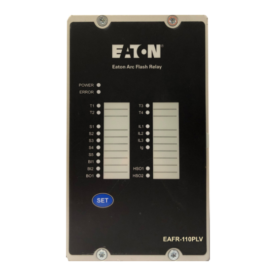
Section 3.3.1) situation, the corresponding LED for that sensor will start flashing and the ERROR LED will activate. The EAFR-110PLV contains 20 indication LEDs. A user definable text list can be slid in under the label pocket for identifying each The Binary I/O LEDs are indicating the I/O-line status. - Page 6 Instruction Booklet IB0191004EN EAFR-110PLV current and arc light sensor relay user manual Effective June 2020 Table 1. LED operation quick guide. Steady on Blinking Action if abnormal POWER Auxiliary supply Auxiliary power connected. Check the power source. Blue disconnected. ERROR System healthy.
- Page 7 Effective June 2020 3.3 Push-button description 3.5 Current threshold setting The EAFR-110PLV contains one single push-button (SET) that can be The EAFR-110PLV relay has four current measurement inputs utilized used for all operational functions of the relay. The SET push-button for three-phase and earth current measurement.
- Page 8 The most convenient way to The EAFR-110PLV functionality, such as tripping logic, is configured set the EAFR-110PLV single relay or more complex arc protection using the dipswitch settings. The relay contains two switch groups system is to use the Standard Arc Schemes for Arc Quenching SW1 and SW2 (see Figure 4).
-
Page 9: Arc Sensors
Instruction Booklet IB0191004EN EAFR-110PLV current and arc light sensor relay user manual Effective June 2020 3.7 Non-volatile memory All critical system data including dipswitch settings and the auto- configuration file described in Section 3.3.1 are stored in EPROM non-volatile memory to ensure correct operation and full self-super- vision, even if auxiliary power is temporarily lost. - Page 10 S1 LED) (see Figure 12). Connect the other end of the cable to a sensor channel on the EAFR-101 or EAFR-110PLV relay (see Figure 9). Figure 12. EAFR-01 sensor connection step 6. Press and hold the SET push button on the front panel for two seconds in order to run the system auto-configuration setting (see Figure 13).
-
Page 11: System Self-Supervision
ERROR LED will turn off. If one or more of the sensors are disconnected, the healthy sensors remain in use and unit remains operational accordingly. The EAFR-110PLV will remain in the Error mode until the disconnected sensors are repaired. -
Page 12: Connections
T1 and T2 relays are normally open type (NO). After powering up, the relay protection is active and operational within 50 ms. 6.1.2 Trip relays T3 and T4 Trip relays T3 and T4 are not utilized in the EAFR-110PLV, and are reserved for future use. EATON www.eaton.com... -
Page 13: Wiring Diagrams
Instruction Booklet IB0191004EN EAFR-110PLV current and arc light sensor relay user manual Effective June 2020 7. Wiring diagrams EAFR-110PLV Station battery T2 / CBFP Lorem ipsum 1A / 5A HSO1 1A / 5A HSO2 1A / 5A 1A / 5A +24V Figure 17. -
Page 14: Dimensions And Installation
EAFR-110PLV current and arc light sensor relay user manual Effective June 2020 8. Dimensions and installation The EAFR-110PLV is door mounted in standard 19 in. (482.6 mm) rack (height of 4U and 1/4 of a relay wide). 175 (6.89) 160 (6.30) 10 (0.39) - Page 15 Ea to n Ar c Fla sh Re lay PO WE R ER RO R 157 (6.18) HS O1 BO 1 HS O2 SE T EA FR -11 0P LV 102 (4.01) Figure 19. EAFR-110PLV dimensions in millimeters (inches) - 3-D view. EATON www.eaton.com...
-
Page 16: Testing
Effective June 2020 9. Testing 84 (3.31) It is recommended that the EAFR-110PLV arc protection relay is 51 (2.01) 16.5 (0.65) tested prior to the equipment being energized. Testing is carried out by simulating arc light to each sensor and verifying the tripping and LED indication. - Page 17 9.4 Testing the arc flash protection unit operation time Verify that the sensor channel indication LED status is changed The EAFR-110PLV operation time test is not required at commission- to ON. ing as it is performed by the manufacturer as a type test and routine Verify that the binary input indication LED status is changed to production test.
- Page 18 Instruction Booklet IB0191004EN EAFR-110PLV current and arc light sensor relay user manual Effective June 2020 9.5 Test plan example Date: Substation: Switchgear: EAFR-110PLV serial number: Preconditions Light only Light + current Remarks Sensor channel 1 setting Sensor channel 2,3,4 setting...
-
Page 19: Troubleshooting Guide
Instruction Booklet IB0191004EN EAFR-110PLV current and arc light sensor relay user manual Effective June 2020 10. Troubleshooting guide 11.5 High speed outputs HSO1 and HSO2 Number Table 5. Troubleshooting guide. Rated voltage 250 Vdc Problem Check Cross reference Continuous carry Sensor does not activate Sensor cable wiring. - Page 20 Instruction Booklet IB0191004EN EAFR-110PLV current and arc light sensor relay user manual Effective June 2020 11.11 Casing and package Protection degree (front) IP 50 Protection degree (back) IP 20 Dimensions - W x H x D mm (W x H x D in.) 102 x 157 x 164 mm (4.02 x 6.18 x 6.46 in.)
-
Page 21: Ordering Codes
Instruction Booklet IB0191004EN EAFR-110PLV current and arc light sensor relay user manual Effective June 2020 12. Ordering codes 12.1 EAFR relay codes Eaton catalog number Eaton style number Part number description EAFR-110P 65C2010G01 Current, point sensor unit EAFR-110F 65C2010G02 Current, fiber loop sensor unit... - Page 22 THIS DOCUMENT SHALL NOT BECOME PART OF OR MODIFY ANY CONTRACT BETWEEN THE PARTIES. In no event will Eaton be responsible to the purchaser or user in contract, in tort (including negligence), strict liability or other-wise for any special, indirect, incidental or consequential damage or loss...
Need help?
Do you have a question about the EAFR-110PLV and is the answer not in the manual?
Questions and answers