
Related Manuals for Eaton easy500, easy700


Summary of Contents for Eaton easy500, easy700
- Page 1 05/10 MN05013003Z-EN Operating Instructions replaces 05/04 AWB2528-1508GB Control Relay 500, 700...
- Page 2 2004, edition date 05/04, edition 05/10, See revision protocol in the “About this manual“ chapter © 2004 by Eaton Industries GmbH, 53105 Bonn Production:DHW Translation:globaldocs GmbH All rights reserved, including those of the translation. No part of this manual may be reproduced in any form...
- Page 3 Danger! Dangerous electrical voltage! Before commencing the installation • Disconnect the power supply of the device. • Ensure a reliable electrical isolation of the low voltage for the 24 volt supply. Only use power supply units complying with • Ensure that devices cannot be accidentally restarted. IEC 60364-4-41 (VDE 0100 Part 410) or HD 384.4.41 S2.
-
Page 5: Table Of Contents
Supplying DC expansion devices ..........31 Connecting inputs ................ 32 2.5.1 Connect digital AC inputs............. 32 2.5.2 Connecting easy DC digital inputs ..........36 2.5.3 Connecting analog inputs............. 37 2.5.4 Connecting high-speed counters and frequency generators ..41 Operating instructions 05/10 MN05013003Z-EN www.eaton.com... - Page 6 Resolution of the analog inputs ........... 86 4.4.5 Function of the analog value comparator function relay ....86 Counter ..................94 4.5.1 Function of the counter function relay ......... 97 High-speed counters, -DA, -DC........100 4.6.1 Frequency Counter ..............100 Operating instructions 05/10 MN05013003Z-EN www.eaton.com...
- Page 7 4.14.1 Negation (contact) ................ 149 4.14.2 Negation (coil) ................149 4.14.3 Permanent contact............... 149 4.14.4 Series circuit................. 150 4.14.5 Parallel connection ............... 150 4.14.6 Parallel circuit operating like a series connection of make contacts..................151 Operating instructions 05/10 MN05013003Z-EN www.eaton.com...
- Page 8 Card startup behavior..............180 Setting the cycle time ..............181 Retention (non-volatile data storage) ........... 181 5.9.1 Permissible markers and function relays ........182 5.9.2 Setting retentive behavior............182 5.9.3 Deleting retentive actual values........... 183 Operating instructions 05/10 MN05013003Z-EN www.eaton.com...
- Page 9 Shipping approvals for 500/700 devices........ 207 8.1.3 Approvals and national approvals for expansion devices ..... 208 8.1.4 Shipping approvals for expansion units 6......208 Dimensions .................. 208 Technical data ................210 8.3.1 Standards ..................210 Operating instructions 05/10 MN05013003Z-EN www.eaton.com...
- Page 10 Parameter display of analog value comparator ......224 8.5.2 Parameter display of counters ............. 225 8.5.3 Parameter display of weekly timer ..........225 8.5.4 Parameter display of timing relay..........225 8.5.5 Compatibility of memory cards ............ 225 Glossary of terms............... 227 Operating instructions 05/10 MN05013003Z-EN www.eaton.com...
-
Page 11: About This Manual
This manual uses the following abbreviated designations for different device models: Designation Device types easy500 EASY512-AB... EASY512-AC... EASY512-DA... EASY512-DC... easy700 EASY719-AB... EASY719-AC... EASY719-DA... EASY719-DC... EASY721-DC... easy-AB EASY512-AB... EASY719-AB... easy-AC EASY512-AC... EASY618-AC-RE EASY719-AC.. easy-DA EASY512-DA... EASY719-DA... Operating instructions 05/10 MN05013003Z-EN www.eaton.com... -
Page 12: Writing Conventions
Draws your attention to interesting tips and supplementary information. For greater clarity, the name of the current chapter is shown in the 1. headline and the name of the current section in the 2. headline. Operating instructions 05/10 MN05013003Z-EN www.eaton.com... -
Page 13: Target Group
The power up of easy must not cause any hazards arising from activated devices, such as unexpected motor startups or power ups. 1.2.1 Improper use easy should not be used as a substitute for safety-related controls such as burner or crane controls, emergency-stop or two-hand safety controls. Operating instructions 05/10 MN05013003Z-EN www.eaton.com... -
Page 14: Overview
1 1.3 Overview 1.3 Overview POW ER COM -ERR Figure 1: easy basic units and expansion devices Operating instructions 05/10 MN05013003Z-EN www.eaton.com... - Page 15 If you wish to wire easy via your PC, use the easySoft-Basic or easySoft-Pro programming software. easySoft allows you to create and test your program (circuit diagram) on the PC. It also allows you to print out your circuit diagram in DIN/IEC, ANSI/CSA or easy format. Operating instructions 05/10 MN05013003Z-EN www.eaton.com...
-
Page 16: Versions
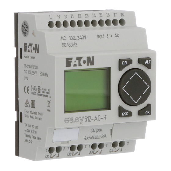
ES C DE L AL T ES C Figure 2: Versions a Supply voltage connection b Inputs c Status LED d Keypad e Interface socket for memory card or PC connection f Outputs g Display Operating instructions 05/10 MN05013003Z-EN www.eaton.com... - Page 17 MFD-80…, MFD-CP4-500 HMI unit Figure 3: Overview with stand-alone HMI unit a easy500 basic units b easy700 basic units c Display/operating unit MFD-80(-B) d Power supply/communication module with MFD(-AC)-CP4-500 interface cable Operating instructions 05/10 MN05013003Z-EN www.eaton.com...
-
Page 18: Key To Part Numbers
EASY512-AC-RCX EASY412-DA-RC EASY512-DA-RC EASY412-DA-RCX EASY512-DA-RCX EASY412-DC-R EASY512-DC-R EASY412-DC-RC EASY512-DC-RC EASY412-DC-RCX EASY512-DC-RCX EASY412-DC-TC EASY512-DC-TC EASY412-DC-TCX EASY512-DC-TCX – EASY719-AB-RC EASY719-AB-RCX – EASY619-AC-RC EASY719-AC-RC EASY619-AC-RCX EASY719-AC-RCX – EASY719-DA-RC – EASY719-DA-RCX EASY619-DC-RC EASY719-DC-RC EASY619-DC-RCX EASY719-DC-RCX EASY621-DC-TC EASY721-DC-TC EASY621-DC-TCX EASY721-DC-TCX Operating instructions 05/10 MN05013003Z-EN www.eaton.com... -
Page 19: Operating Principles
Move to previous menu level Cancel entries since last OK ÍÚ Change menu item Change value ú í Change place P button function: ú Í Input P1, Input P2 í Ú Input P3, Input P4 Operating instructions 05/10 MN05013003Z-EN www.eaton.com... -
Page 20: Choosing The Main And System Menu
EASY204- DP (Profibus-DP bus gateway) 1.5.3.2 Toggling between weekday, time display and date display (only on devices with clock) .2..5..MO 11:50 .2..5..34 2010-04-01 Operating instructions 05/10 MN05013003Z-EN www.eaton.com... -
Page 21: Status Indicator
: DC expansion functioning correctly : Bus coupling module detected GW flashes: Only easy200-easy detected. I/O expansion not detected. 04.03.17 Display of actual device date : When the power supply is switched on, easy switches to STOP mode Operating instructions 05/10 MN05013003Z-EN www.eaton.com... -
Page 22: Led Display
PROGRAM... DELETE ? DELETE PROG CARD... PROGRAM... DELETE PROG CARD... DEVICE-CARD REPLACE ? CARD-DEVICE DELETE CARD DEVICE-CARD CARD-DEVICE REPLACE ? DELETE CARD DEVICE-CARD CARD-DEVICE DELETE CARD DELETE ? Operating instructions 05/10 MN05013003Z-EN www.eaton.com... - Page 23 SET CLOCK.. OS: 1.00.027 CRC: 02752 PROGRAM... RUN Æ Display for date and time STOP setting PARAMETER INFO... SET CLOCK.. HH:MM --:-- HH:MM 14:23 CLOCK.æ SUMMER TT.MM --.-- TT.MM 17.03 YEAR ____ TIME... YEAR 2010 Operating instructions 05/10 MN05013003Z-EN www.eaton.com...
- Page 24 TT.MM:00.00æ HH:MM:00:00 DIFF: 00:00 Æ SET CLOCK.. NONE å SUMMER TIME… RULE... SUMMER START SUMMER END æ Æ SUMMER START SET CLOCK.. NONE å SUMMER END SUMMER TIME… RULE... æ --Æ TT.MM:00.00æ HH:MM:00:00 DIFF: 00:00 Operating instructions 05/10 MN05013003Z-EN www.eaton.com...
- Page 25 CHANGE PW CHANGE PW ACTIVATE PW PASSW.. Change/ XXXX delete password å Æ å Æ PROGRAM PASSWORD... PROGRAM PARAMETER å RANGE... PARAMETER CLOCK å CLOCK OPRTNG MODEæ OPRTNG MODEæ INTERFACE. å INTERFACE DEL PROGå DEL PROG Operating instructions 05/10 MN05013003Z-EN www.eaton.com...
-
Page 26: Selecting Or Toggling Between Menu Items
Í • Value HH:MM 14:23 ú í TT.MM 17.03 • Change position with YEAR 2010 Í Ú • Change values with Flashing values/menus are shown in grey in this manual. Operating instructions 05/10 MN05013003Z-EN www.eaton.com... -
Page 27: Set Value
Select value HH:MM 14:23 ú í TT.MM 17.03 Select digit YEAR 2010 Í Ú Change value at digit Values Store entries Digits Current value at the position (can be changed, Cursor = 3) Retain previous value Operating instructions 05/10 MN05013003Z-EN www.eaton.com... - Page 28 1 1.5 operating principles Operating instructions 05/10 MN05013003Z-EN www.eaton.com...
-
Page 29: Installation
Verify isolation from the supply. • Cover adjacent live parts. easy is installed in the following order: • Assemble devices if necessary, • Mounting, • Wiring up the inputs, • Wiring up the outputs, • Connecting the power supply. Operating instructions 05/10 MN05013003Z-EN www.eaton.com... -
Page 30: Mounting
Easy will clip into place and will be secured by the built-in spring mechanism. ▶ Check that the device is seated firmly. The device is mounted vertically on a top-hat rail in the same way. Operating instructions 05/10 MN05013003Z-EN www.eaton.com... -
Page 31: Screw Mounting
Mounting on a mounting plate requires the use of fixing brackets which are fixed to the back of easy. The fixing brackets are available as an accessory. easy600 and easy700: Fasten each device with at least three fixing brackets. EASY200-EASY: easy500: easy600, easy700: Figure 5: Screw mounting Operating instructions 05/10 MN05013003Z-EN www.eaton.com... -
Page 32: Connecting The Expansion Device
▶ Open the easy-Link connections on the side of both easy devices. ▶ Fit the easyLink data connector EASY-LINK-DS in the opening provided on the expansion device. ▶ Plug the devices together. ▶ Proceed in the reverse order to dismantle the device. Operating instructions 05/10 MN05013003Z-EN www.eaton.com... -
Page 33: Terminations
Ensure that reed relay contacts or proximity switches are not used as the switching device for switching on the power supply. 2.4.2 Supplying AC basic units EASY…-AB-RC(RCX), EASY…-AC-R(RC, RCX) Figure 7: Supply voltage to AC basic unit Operating instructions 05/10 MN05013003Z-EN www.eaton.com... -
Page 34: Supplying Ac Expansion Units
Press the interface cover back onto the shaft if you no longer need the interface. CAUTION A short current surge will be produced when switching on for the first time. Do not switch on easy with reed contacts because these could possibly burn or stick. Operating instructions 05/10 MN05013003Z-EN www.eaton.com... -
Page 35: Supplying Dc Basic Units
24 V H Figure 10: Power supply on the DC expansion units → easy-DC and easy-DA are protected against reverse polarity. To ensure that easy works correctly, ensure that the polarity of each terminal is correct. Operating instructions 05/10 MN05013003Z-EN www.eaton.com... -
Page 36: Connecting Inputs
2.5.1.1 Connect digital AC inputs to the basic unit Figure 12: Connecting easy-AC and easy-AB digital inputs Operating instructions 05/10 MN05013003Z-EN www.eaton.com... - Page 37 115 V AC I7, I8 6 mA at 230 V AC/4 mA at 115 V easy700 I9 - I12 0.5 mA at 230 V AC/0.25 mA at 115 V AC easy600 R1 - R12 Operating instructions 05/10 MN05013003Z-EN www.eaton.com...
- Page 38 Two-wire proximity switches have a residual current with the “0” state. If this residual current is too high, the easy input may only detect a “1” signal. Use therefore the inputs I7, I8. An additional input circuit is required if more inputs are needed. Operating instructions 05/10 MN05013003Z-EN www.eaton.com...
- Page 39 Limitation of the input current through resistors Complete devices for increasing the input current are available under the part no. EASY256-HCI. Figure 17: easy with EASY256-HCI → The increased capacitance increases the drop-off time by approx. 40 ms. Operating instructions 05/10 MN05013003Z-EN www.eaton.com...
-
Page 40: Connecting Easy Dc Digital Inputs
15 - 28.8 V 3.3 mA at 24 V DC I11, I12 ≧ 8 V DC 2.2 mA at 24 V easy600 R1 - R12 15 - 28.8 V 3.3 mA at 24 V DC Operating instructions 05/10 MN05013003Z-EN www.eaton.com... -
Page 41: Connecting Analog Inputs
Supplying loads such as motors, solenoid valves or contactors and easy from the same supply voltage may cause interference of the analog input signal when switching. Operating instructions 05/10 MN05013003Z-EN www.eaton.com... - Page 42 Ensure that the common reference potential is grounded or monitored by a ground fault monitoring device. Observe the applicable regulations. EASY200-POW +12 V L01h N01 h Figure 20: easy-AB analog input, connection of reference potentials Operating instructions 05/10 MN05013003Z-EN www.eaton.com...
- Page 43 DA : +12 V Figure 22: Analog setpoint potentiometer with 24 V DC power feed 2.5.3.5 Brightness sensor -AB, -DA, -DC 12 V 0...10 V +12 V +...V Figure 23: Connection of a brightness sensor, analog input Operating instructions 05/10 MN05013003Z-EN www.eaton.com...
- Page 44 The following values apply: • 4 mA = 1.9 V • 10 mA = 4.8 V • 20 mA = 9.5 V (according to U = R x I = 478 Ω x 10 mA ~ 4.8 V). Operating instructions 05/10 MN05013003Z-EN www.eaton.com...
-
Page 45: Connecting High-Speed Counters And Frequency Generators
If the counter frequency is high: Not all the signals of the high-speed counter can be monitored for processing in the circuit diagram. easy will only process a randomly logged state. Operating instructions 05/10 MN05013003Z-EN www.eaton.com... -
Page 46: Connecting Outputs
115 V 230 V 1000 W 0 V H, N 10 x 58 W 25 000 F 8 A/B 16 L1, L2, L3 (115/230 V h) + 24 V H Figure 28: EASY512-…-R… relay outputs Operating instructions 05/10 MN05013003Z-EN www.eaton.com... - Page 47 Do not exceed the maximum voltage of 250 V AC on a relay contact. If the voltage exceeds this threshold, flashover may occur at the contact, resulting in damage to the device or a connected load. Operating instructions 05/10 MN05013003Z-EN www.eaton.com...
-
Page 48: Connecting Transistor Outputs
Q5 Q6 Q7 F10 A 0 V H f 2.5 A + 24 V H 24 V H 0.5 A 0.5 A (20.4 – 28.8 V H) 5 W/24 V Figure 32: EASY7-…-T… transistor outputs Operating instructions 05/10 MN05013003Z-EN www.eaton.com... - Page 49 Please note the following when switching off inductive loads: • Suppressed inductive loads cause less interference in the entire electrical system. It is generally recommended to connect the suppressor as close as possible to the inductance. Operating instructions 05/10 MN05013003Z-EN www.eaton.com...
-
Page 50: Behavior In The Event Of A Short-Circuit/Overload
24 V DC power supply • 12 DC inputs, • 6 relay outputs EASY620-..-TE • 12 DC inputs, • 8 transistor outputs EASY202-RE 2 relay outputs Note: Cannot be operated on an EASY7..-DA-R... Special expansion units see current catalogue Operating instructions 05/10 MN05013003Z-EN www.eaton.com... -
Page 51: Local Expansion Module
Units may be destroyed if the value 400 V AC +10 % is exceeded, and may cause the malfunction of the entire system or machine! → Basic unit and expansion unit can be provided with different DC power supplies. Operating instructions 05/10 MN05013003Z-EN www.eaton.com... -
Page 52: Remote Expansion
Connecting remote expansion units to easy → Terminals E+ and E- of the EASY200-EASY are protected against short-circuits and polarity reversal. Functionality is only ensured if "E+" is connected with "E+" and "E-" with "E-". Operating instructions 05/10 MN05013003Z-EN www.eaton.com... -
Page 53: Connecting Bus Systems
→ The range and the functions of the bus gateways are being continually further developed. Our latest product range or Internet online catalogue contains the valid and available bus modules. Operating instructions 05/10 MN05013003Z-EN www.eaton.com... - Page 54 2 Installation 2.8 Connecting bus systems Operating instructions 05/10 MN05013003Z-EN www.eaton.com...
-
Page 55: Placing Into Operation
• French ESPANOL • Spanish • Italian • Portuguese • Dutch • Swedish • Polish • Turkish • Czech • Hungarian ▶ Press OK to confirm your choice and press ESC to exit the menu. Operating instructions 05/10 MN05013003Z-EN www.eaton.com... -
Page 56: Operating Modes
With easy, however, you no longer have to connect up components individually. At the push of a few buttons, the easy circuit diagram produces all the wiring. All you have to do is then connect any switches, sensors, lamps or contactors you wish to use. Operating instructions 05/10 MN05013003Z-EN www.eaton.com... - Page 57 Lamp controller with relays In the following example, easy carries out all the wiring and performs the tasks of the circuit diagram shown below. L01+ L01- +24V 0V I1 I2 L01- Figure 38: Lamp control using easy Operating instructions 05/10 MN05013003Z-EN www.eaton.com...
-
Page 58: Circuit Diagram Display
Relay K1 is represented by the relay coil . The symbol Ä identifies the coil's function, in this case a relay coil acting as a contactor. is one of up to eight easy output relays in the basic unit. Operating instructions 05/10 MN05013003Z-EN www.eaton.com... -
Page 59: From The First Contact To The Output Coil
• From the left contact field, press ALT to insert a new, empty rung. • The contact under the cursor can be changed between a N/O and N/C contact by pressing the ALT button. Operating instructions 05/10 MN05013003Z-EN www.eaton.com... - Page 60 Changes that have been made to the circuit diagram are not saved. → easy saves all the necessary circuit diagram and program data retentively in the internal data memory. Once you have connected pushbutton actuators S1 and S2, you can test your circuit diagram straight away. Operating instructions 05/10 MN05013003Z-EN www.eaton.com...
-
Page 61: Testing The Circuit Diagram
A circuit diagram does not have to be completed before you can test parts of it with easy. easy simply ignores any incomplete wiring that is not yet working and only uses the finished wiring. Operating instructions 05/10 MN05013003Z-EN www.eaton.com... -
Page 62: Deleting The Circuit Diagram
If you use the first option, you will have to select some of the elements in order to create and connect up your circuit diagram. The second, faster option is what you learned in the example. In this case you create the entire rung from left to right. Operating instructions 05/10 MN05013003Z-EN www.eaton.com... -
Page 63: Wiring With
If you press ESC in Entry mode, easy will undo the most recent changes. Press ALT to switch to Connect mode for wiring contacts and relays. Press ALT again to return to Move. Operating instructions 05/10 MN05013003Z-EN www.eaton.com... - Page 64 Time switch = function relay with contacts 4.1.2.5 Relay Relays are switching devices which are electronically simulated in easy. They actuate their contacts according to their designated function. A relay consists of at least one coil and contact. Operating instructions 05/10 MN05013003Z-EN www.eaton.com...
- Page 65 The contacts (N/O contact) of the time switches are always set to logic 0. The advantage of this process is that you can use the same circuit diagram on all easy500, easy700, easy-AB, easy-AC, easy-DA and easy-DC devices. Operating instructions 05/10 MN05013003Z-EN www.eaton.com...
- Page 66 – … expansion easy output … … (expansion or S auxiliary marker) (as marker) Timer function relays … … Jump label – … … Year Time Switch … Y1…Y8 Master reset, (central reset) … Z1…Z3 Operating instructions 05/10 MN05013003Z-EN www.eaton.com...
-
Page 67: Relays, Function Relays
0. The advantage of this process is that you can use the same circuit diagram on all easy500, easy700, easy-AB, easy-AC, easy-DA and easy-DC devices. Furthermore, you can use outputs that are not physically present as markers. - Page 68 The circuit diagram display performs two functions: • In STOP mode it is used to edit the circuit diagram. • In RUN mode it is used to check the circuit diagram using the Power flow display. Operating instructions 05/10 MN05013003Z-EN www.eaton.com...
-
Page 69: Saving And Loading Circuit Diagrams
Completed circuit diagrams are transferred between your PC and easy via the connecting cable. Once you have transferred a circuit diagram, simply run easy straight from your PC. Details on the program and transferring circuit diagrams, (→ Section "6.8 Soft“, page 200). Operating instructions 05/10 MN05013003Z-EN www.eaton.com... -
Page 70: Working With Contacts And Relays
If the field is empty, easy will enter contact or the coil ÍÚ to a contact or coil field. ú í ▶ Move the cursor using the buttons ▶ Press OK to switch to Entry mode. Operating instructions 05/10 MN05013003Z-EN www.eaton.com... - Page 71 4.2.1.2 Deleting contacts and relay coils ÍÚ to a contact or coil field. ú í ▶ Move the cursor using the buttons ▶ Press DEL. The contact or the relay coil will be deleted, together with any connections. Operating instructions 05/10 MN05013003Z-EN www.eaton.com...
-
Page 72: Creating And Modifying Connections
Never work backwards, ( → section “6.1.1.2 Example: Do not wire I1-Q4-I3o backwards”, page 188). z-----k hI2-I4-ÄQ2 When wiring more than three contacts in series, use an M or N marker. I1-Q4-I3-ÄM1 I2-I4-M1-ÄQ2 Operating instructions 05/10 MN05013003Z-EN www.eaton.com... -
Page 73: Inserting And Deleting A Rung
▶ Delete all the contacts and relay coils from the rung. ▶ Position the cursor on the first contact field of the empty rung. ▶ Press DEL. The subsequent rung(s) will be “pulled up” and any existing links between rungs will be retained. Operating instructions 05/10 MN05013003Z-EN www.eaton.com... -
Page 74: Switching With The Cursor Buttons
P: button function wired and active. FR 15:59 P2: button function wired, active and P2 button Í pressed ..STOP • • P-: button function wired and not active. • Empty field: P buttons not used. Operating instructions 05/10 MN05013003Z-EN www.eaton.com... -
Page 75: Checking The Circuit Diagram
You can follow energized connections across all rungs by scrolling the display up and down. → The power flow display will not show signal fluctuations in the millisecond range. This is due to the inherent delay factor of LCD displays. Operating instructions 05/10 MN05013003Z-EN www.eaton.com... -
Page 76: Coil Functions
The last coil in the circuit diagram determines the status of the relay. When controlling a contactor or relay, the control coil is only present once. If you are creating parallel circuits, use Set, Reset as a coil function. Operating instructions 05/10 MN05013003Z-EN www.eaton.com... - Page 77 Representation in easy: ÄQ1 ÄQ8 • Output relays Q: (depending on type) ÄM1 ÄM16 ÄN1 ÄN16 • Markers M, N: ÄD1 ÄD16 • Function relays (Text) D: ÄS1 ÄS8 • Output relays S: Ä:1 Ä:8 • Jumps: Operating instructions 05/10 MN05013003Z-EN www.eaton.com...
- Page 78 Signal diagram, cycle pulse on falling edge Representation in easy: èM1 èM16 èN1 èN16 • Markers M, N: è:1 è:8 • Jumps: → Physical outputs should not be used as a cycle pulse is generated. Operating instructions 05/10 MN05013003Z-EN www.eaton.com...
- Page 79 Relays S: → A coil is automatically switched off in the event of a power failure and in STOP mode. Exception: Retentive coils retain signal 1 (→ Section "5.9 Retention (non-volatile data storage)“, page 181). Operating instructions 05/10 MN05013003Z-EN www.eaton.com...
- Page 80 → A latched relay is automatically switched off if the power fails or if the device is in STOP mode. Exception: Retentive coils retain signal 1 (→ Section "5.9 Retention (non-volatile data storage)“, page 181). Operating instructions 05/10 MN05013003Z-EN www.eaton.com...
-
Page 81: Function Relays
This takes the last status of the coils into account. Only use the coil of a function relay once. Exception: When working with jumps, the same coil can be used several times. Operating instructions 05/10 MN05013003Z-EN www.eaton.com... -
Page 82: Example: With Function Relay Timer And Counter Relay
1 function relay. → Press OK to call up the easy parameter display. ▶ Move the cursor onto the and press OK. The parameter set for the counter is displayed. Operating instructions 05/10 MN05013003Z-EN www.eaton.com... - Page 83 . It is set at the top left of the parameter display. means here the time base second. Ü Ú ▶ Select the symbol by pressing the button. T1 Ü í ▶ Use the to move to the first time setpoint T1 Ü Operating instructions 05/10 MN05013003Z-EN www.eaton.com...
- Page 84 C1 N character on the bottom row will change to . The contact of counter 0010 switches. â C:0010 The counter contact triggers the timing relay. This causes the warning light to flash at output Q1. Operating instructions 05/10 MN05013003Z-EN www.eaton.com...
- Page 85 If you want to prevent other people from modifying the parameters, change the access enable symbol from + to – when creating the circuit diagram and setting parameters. You can then protect the circuit diagram with a password. Operating instructions 05/10 MN05013003Z-EN www.eaton.com...
-
Page 86: Analog Value Comparator/Threshold Value Switch
The analog value comparison function relay works in easy500 and easy700 and in easy400, easy600. The setpoints are converted to the new resolution of the analog inputs. The setpoint 5.0 (easy400, easy600) is converted to the setpoint 512 (easy500, easy700). Operating instructions 05/10 MN05013003Z-EN www.eaton.com... - Page 87 A1 function relay Value input I1 A1 function relay Value input I2 GE (greater than/equal to) LE (less than/equal to) GE (greater than/equal to) Setpoint LE (less than/equal to) Setpoint GE (greater than/equal to) Setpoint LE (less than/equal to) Setpoint Operating instructions 05/10 MN05013003Z-EN www.eaton.com...
-
Page 88: Circuit Diagram Display With Analog Value Comparator
New functions have been added to the parameter display of easy500 and easy700. The easy400 and easy600 parameters can be found at the following points. easy400/600- easy500/700- Parameters Parameters ANALOG A1 GE Æ I1 AA I2 BB > æ > Operating instructions 05/10 MN05013003Z-EN www.eaton.com... -
Page 89: Parameter Display In Run Mode
Actual value, e.g.: analog input 0249 Factor is not used 0000 æ Actual comparison value, e.g.: constant 0350 Factor is not used 0000 Offset is not used 0000 The switching hysteresis is +/– 25 0025 Operating instructions 05/10 MN05013003Z-EN www.eaton.com... -
Page 90: Resolution Of The Analog Inputs
Set the switching hysteresis to a value so that interference signals will not cause accidental switching. A value of 0.2 V (value 20 without gain) must be observed as a safety value. Operating instructions 05/10 MN05013003Z-EN www.eaton.com... - Page 91 4: setpoint minus hysteresis The N/O contact switches off when the actual value at I7 exceeds the setpoint value plus hysteresis. If the actual value at I7 falls below the setpoint value, the N/O contact switches on. Operating instructions 05/10 MN05013003Z-EN www.eaton.com...
- Page 92 The N/O contact switches off when the actual value at I7 exceeds the setpoint value plus hysteresis. If the actual value at I7 equals or falls below the setpoint value, the N/O contact switches on. Operating instructions 05/10 MN05013003Z-EN www.eaton.com...
- Page 93 The N/O contact switches on if the actual value at I8 (multiplied by F1) reaches the configured setpoint value. If the actual value falls below the setpoint value minus hysteresis, the N/O contact switches off. Operating instructions 05/10 MN05013003Z-EN www.eaton.com...
- Page 94 4: setpoint minus hysteresis The N/O contact switches if the actual value at I7 is equal to the setpoint value. The N/O contact switches off when the actual value at I7 falls below the setpoint minus hysteresis. Operating instructions 05/10 MN05013003Z-EN www.eaton.com...
- Page 95 4: setpoint minus hysteresis The N/O contact switches if the actual value at I7 reaches the setpoint value. The N/O contact switches off when the actual value at I7 falls below the setpoint value minus hysteresis. Operating instructions 05/10 MN05013003Z-EN www.eaton.com...
- Page 96 This switching hI7u---RQ1 point has a 8 V DC (easy-DA, easy-DC) and 9.5 V (easy-AB) signal. I5---k Parameter settings: Switch-on Switch-off A1 LT The switch point is Æ implemented via I7 (digital switching signal). æ 0500 Operating instructions 05/10 MN05013003Z-EN www.eaton.com...
- Page 97 To compare two analog values, you can use the following circuit. In this case, A1-------ÄM9 the comparison determines whether I7 is less than I8. Parameter settings of the analog value comparator A1 LT Æ æ 0025 Operating instructions 05/10 MN05013003Z-EN www.eaton.com...
-
Page 98: Counter
Counter modes Counter Operating Mode C1 to C12 Up/Down Counter C13, C14 N or H Up/down counters or high-speed up counters (easy-DA, easy-DC) C15, C16 N or F Up/down counters or frequency counters (easy-DA, easy-DC) Operating instructions 05/10 MN05013003Z-EN www.eaton.com... - Page 99 New functions have been added to the parameter display of easy500 and easy700. The easy400 and easy600 parameters can be found at the following points. easy400/600- easy500/700- fAAAAg Parameters Parameters Ä sDIR n AAAA S AAAAA AAAAA Ä sCNT d Ä yRES b Operating instructions 05/10 MN05013003Z-EN www.eaton.com...
- Page 100 The maximum counter frequency depends on the maximum cycle time. The following formula is used to determine the maximum counter frequency: x 0.8 2 x t = maximum counter frequency = maximum cycle time 0.8 = Correction factor Operating instructions 05/10 MN05013003Z-EN www.eaton.com...
-
Page 101: Function Of The Counter Function Relay
Q4 remains switched on until I7 resets counter C1 to zero with the RC1 coil. Circuit diagram display Parameter settings of the counter C1 I6-------CC1 C1 N C1-------ÄQ4 00100 I7-Q4----RC1 Operating instructions 05/10 MN05013003Z-EN www.eaton.com... - Page 102 Circuit diagram display Parameter settings of the counter C2 I6-C3----CC2 C2 N C2------uÄM8 01000 dRC2 hCC3 C3-------ÄQ2 I8-Q2----RC3 Parameter settings of the counter C3 25000 pulses are counted. C3 N 25 x 1000 = 25000 00025 Operating instructions 05/10 MN05013003Z-EN www.eaton.com...
- Page 103 The counter has the value 450 before the power supply is switched off. T13 - T16 D 1 - D 8 Figure 55: Retentive counter a The numerical value 450 is retained even after a power outage. U = supply voltage of the device Operating instructions 05/10 MN05013003Z-EN www.eaton.com...
-
Page 104: High-Speed Counters, -Da, -Dc
4.6.1.2 Measuring procedure The pulses on the input are counted for one second irrespective of the cycle time, and the frequency is determined. The measurement result is provided as an actual value. Operating instructions 05/10 MN05013003Z-EN www.eaton.com... - Page 105 Setpoint, constant from 00000 to 01000 (32000 is a possible setting, the maximum frequency is 1 kHz) In the parameter display of a counter relay you change the mode, the setpoint and the enable of the parameter display. Operating instructions 05/10 MN05013003Z-EN www.eaton.com...
- Page 106 • Range A: the counter is enabled. After a frequency above the setpoint was measured for the first time, contact C15 (C16) switches. • Range B: If the actual value falls below the setpoint, the contact is reset. The removal of the enable signal resets the actual value to zero. Operating instructions 05/10 MN05013003Z-EN www.eaton.com...
-
Page 107: High-Speed Counters
I1 and I2. This counter relay allows you to count events independently of the cycle time. The high-speed counters allow you to enter an upper threshold value as a comparison value. The C13 and C14 high-speed counters are not dependent on the cycle time. Operating instructions 05/10 MN05013003Z-EN www.eaton.com... - Page 108 This has the advantage that the cycle time of the device is only burdened with the counting when it is taking place. If the high-speed counter is not enabled, the cycle time of the device is shorter. Operating instructions 05/10 MN05013003Z-EN www.eaton.com...
- Page 109 If a counter relay is retentive, the actual value is retained when the operating mode changes from RUN to STOP as well as when the supply voltage is switched off. When easy is restarted in RUN mode, the counter relay continues with the retentively stored actual value. Operating instructions 05/10 MN05013003Z-EN www.eaton.com...
- Page 110 In the examples it must be remembered that there may be a time difference of up to one program cycle between the setpoint/actual value comparison and the processing of the result. This may cause deviations in values. Operating instructions 05/10 MN05013003Z-EN www.eaton.com...
- Page 111 • A3 = comparison, if C13 and C14 are equal, both drives can be activated. • The hysteresis value of A1, A2 and A3 depends on the resolution of the transducer and the mechanical system. Operating instructions 05/10 MN05013003Z-EN www.eaton.com...
- Page 112 -------uCC13 hCC14 Parameter settings of the counter C14 Parameter setting of analog value comparators A1 and A2 A1 LT A2 LT Æ Æ æ æ 0015 0015 Parameter settings A3 A1 EQ Æ æ 0020 Operating instructions 05/10 MN05013003Z-EN www.eaton.com...
-
Page 113: Text Display
If a coil is triggered, the text is shown in the display. The text display does not have a parameter display in the PARAMETER menu. 4.7.2 Retention The texts D1 to D8 can be operated with retentive actual values (contacts). Operating instructions 05/10 MN05013003Z-EN www.eaton.com... -
Page 114: Scaling
D1 is designed for alarm text. If a text has been assigned to D1 and it is activated, this text is shown permanently in the display until: • The coil D1 is reset to 0. Operating instructions 05/10 MN05013003Z-EN www.eaton.com... -
Page 115: Text Entry
Setpoint entries in text displays are useful if the PARAMETERS menu is not available for the display or entry. They are also used if the operator is to receive a message as to which setpoint he is to change. Operating instructions 05/10 MN05013003Z-EN www.eaton.com... - Page 116 ▶ Pressing the OK button causes the cursor to return to Selection mode. STIR M:S The modified value is accepted. S : 015:00 ACT:008:34 BREAD ROLLS Press the ESC button to leave Entry mode. STIR M:S S : 015:00 ACT:008:34 BREAD ROLLS Operating instructions 05/10 MN05013003Z-EN www.eaton.com...
-
Page 117: Weekly Timer
A weekly timer can be integrated into your circuit in the form of a contact. Ö1u------ÄQ1 Ö2k Contact Coil Ö1 Ö8 Contact of the weekly timer Operating instructions 05/10 MN05013003Z-EN www.eaton.com... -
Page 118: Parameter Display And Parameter Set For Weekly Timer
Parameter display in RUN mode: Ö1 A 11:30 Selected channel, current time (only in RUN) MO-FR Weekday(s) from - to 06:45 19:30 â Closing delay Off time Contact has not switched. â Contact has switched. Operating instructions 05/10 MN05013003Z-EN www.eaton.com... -
Page 119: Changing Time Switch Channel
4.8.3.1 Work days example Ö The time switch switches on Monday to Friday between 6:30 and 9:00 and between 17:00 and 22:30. Ö1 Ö1 MO-FR MO-FR 06:30 17:00 09:00 22:30 Figure 59: Work days signal diagram Operating instructions 05/10 MN05013003Z-EN www.eaton.com... - Page 120 22:00 on Monday and switches off at 6:00 on Tuesday. Ö3 22:00 06:00 Figure 61: Night switching signal diagram → If the break time is before the closing delay, easy will switch off on the following day. Operating instructions 05/10 MN05013003Z-EN www.eaton.com...
- Page 121 4.8.3.6 24 hour switching example The time switch is to switch for 24 hours. Switch-on time at 00:00 on Monday and switch-off time at 00:00 on Tuesday. Ö1 Ö1 00:00 --:-- --:-- 00:00 Operating instructions 05/10 MN05013003Z-EN www.eaton.com...
-
Page 122: Operating Hours Counter
Setpoint in hours Actual value of the operating hours counter [h] In the parameter display of an operating hours counter you change the setpoint in hours and the enable of the parameter display. Operating instructions 05/10 MN05013003Z-EN www.eaton.com... -
Page 123: Value Range Of The Operating Hours Counter
The actual value is then set to zero. → Operating mode change RUN, STOP, power On, Off, Delete program, Change program, Load new program. All these functions do not clear the actual value of the operating hours counter. Operating instructions 05/10 MN05013003Z-EN www.eaton.com... - Page 124 A keyswitch at input I8 resets the associated operating hours counter after maintenance has been completed. Circuit diagram display Parameter settings of operating hours counter O2 N1-------ÄO2 N2-------ÄO3 000500 O2u------ÄQ4 I8uO2----RO2 hO3----RO3 Parameter settings of operating hours counter O3 000800 Operating instructions 05/10 MN05013003Z-EN www.eaton.com...
- Page 125 Parameter setting of timing Text of text display D2 relay T1 T1 Ü MAINTENANCE 02,000 REQUIRED 01,500 HRS:000501 MACHINE 01 Text of text display D3 Text of text display D4 MAINTENANCE RUNTIME REQUIRED MACHINE HRS:000800 HRS:001955 MACHINE 02 Operating instructions 05/10 MN05013003Z-EN www.eaton.com...
-
Page 126: Timing Relay
0. 2. easy400 and easy600: • The timing relay output starts with a pause for the flash function. • The time is not counted until the trigger coil is deactivated and then reactivated. Operating instructions 05/10 MN05013003Z-EN www.eaton.com... -
Page 127: Parameter Display And Parameter Set For A Timing Relay
New functions have been added to the parameter display of easy500 and easy700. The easy400 and easy600 parameters can be found at the following points. easy400/600- easy500/700- Parameters Parameters T1 X nAA.BBn AA.BB Ä sTRG yRES AA.BB AA.BB Parameter display in RUN mode: Operating instructions 05/10 MN05013003Z-EN www.eaton.com... -
Page 128: Retention
On- and off-delayed switching with random time, 2 time setpoints ?Xâ ü Single pulse switching Ü Flash switching, mark-to-space ratio = 1:1, 2 time setpoints Ü Flash switching, mark-to-space ratio = 1:1, 2 time setpoints Operating instructions 05/10 MN05013003Z-EN www.eaton.com... -
Page 129: Time Range
With the time base “s” the value is accepted as a “value in ms”. The last position is rounded up to a zero or five. Equation: Time setpoint = ( Value x 10) in [ms] Value, e.g. Analog input Time setpoint in [s] 00.00 01.00 03.00 05.00 1023 10.23 Operating instructions 05/10 MN05013003Z-EN www.eaton.com... - Page 130 (minutes)”. Rule: Time setpoint = Value divided by 60, integer result = Number of hours, remainder is the number of minutes Value, e.g. Analog input Time setpoint in [H:M] 00:00 01:40 05:00 10:06 1023 17:03 Operating instructions 05/10 MN05013003Z-EN www.eaton.com...
-
Page 131: Function Of The Timing Relay Function Relay
If the trigger coil drops out while the on-delay time is running down, the timing relay stops the on-delay time and resets the actual value t to 0. After the trigger coil is set again, the entire on-delay time is run down. Operating instructions 05/10 MN05013003Z-EN www.eaton.com... - Page 132 Figure 66: Signal diagram of timing relay, off-delayed (with/without random switching with retriggering) Range E: The trigger coil drops out twice. The actual time is cleared and the set time elapses completely (retriggerable switch function). Operating instructions 05/10 MN05013003Z-EN www.eaton.com...
- Page 133 • Range F: The Reset coil resets the relay after the on delay has elapsed • Range G: After the reset coil is activated, the internal time counter is reset. The switching contact remains switched off. The function relay waits for a new trigger pulse. Operating instructions 05/10 MN05013003Z-EN www.eaton.com...
- Page 134 If the trigger coil is actuated again, the actual time t is set to 0. If the trigger coil subsequently drops out, the set off-delay time is run down again. This behavior is also the same for on-delay and off-delay modes with random switching. Operating instructions 05/10 MN05013003Z-EN www.eaton.com...
- Page 135 • Range D: The reset coil resets the timing relay. • Range E: The reset coil resets the timing relay. The Trigger coil is still activated after the Reset coil has been deactivated and the time is still running. Operating instructions 05/10 MN05013003Z-EN www.eaton.com...
-
Page 136: Examples Timing Relay
4.10.6 Examples timing relay 4.10.6.1 Example: timing relay, on-delayed In this example a conveyor belt starts 10 s after the system is powered up. Circuit diagram display Parameter settings of timing relay T1 I5-------TT1 T1 X T1-------ÄQ1 10,000 Operating instructions 05/10 MN05013003Z-EN www.eaton.com... - Page 137 This example shows a continuous flash pulse function. Outputs Q3 or Q4 flash according to the marker states of M8 or M9. Circuit diagram display Parameter settings of timing relay T5 T5 Ü ---------DD5 T5uM8----ÄQ3 02,000 hM9----ÄQ4 01,000 Operating instructions 05/10 MN05013003Z-EN www.eaton.com...
- Page 138 T8-------ÄQ1 15:00 T13 - T16 D 1 - D 8 Figure 73: Function of the circuit 1: power supply 2: status of marker M9 and thus trigger signal T8 3: status of make contact T8 Operating instructions 05/10 MN05013003Z-EN www.eaton.com...
-
Page 139: Jumps
Ä Ä Coil /jumped range/Contact ,Coil /jumped range/ Contact etc. CAUTION If rungs are skipped, the states of the coils are retained. The time of started timing relays continues to run. Operating instructions 05/10 MN05013003Z-EN www.eaton.com... -
Page 140: Power Flow Display
---------Ä:8 ---------Ä:8 Jump to label 8. Section to jump label 8 skipped. :2-------ÄQ2 :2------- : Q2-I3----TT2 Q2-I3---- : T2-------ÄQ1 T2------- : Jump label 8, circuit diagram processed from this point on. I1 2------- I12------ÄD1 ÄD1 Operating instructions 05/10 MN05013003Z-EN www.eaton.com... -
Page 141: Year Time Switch
The parameters for the switch-on and switch-off times for a continuous period of time are configured in two neighbouring channels (A and B or B and C). Operating instructions 05/10 MN05013003Z-EN www.eaton.com... -
Page 142: Behavior In The Event Of A Power Failure
01 to 31 --.xx.00 Month 01 to 12 --.--.00 Year, two-digit 00 to 99 Parameter display in RUN mode: Selected channel 04.01.01 Closing delay OFF 04.12.31 Off time â Contact has not switched. â Contact has switched. Operating instructions 05/10 MN05013003Z-EN www.eaton.com... -
Page 143: Changing Time Switch Channel
(→ section “ Example 8: Selecting a time range of two days spanning the turn of the year (2-channel)”, page 145). • ON = --/--/Year, OFF = --/--/Year, • ON = --/Month/Year, OFF = --/Month/Year • ON = Day/Month/Year, OFF = Day/Month/Year Operating instructions 05/10 MN05013003Z-EN www.eaton.com... -
Page 144: Entry Rules
OFF: Month --.XX.-- OFF --.XX.-- 4.12.6.3 Rule 3 ON: Year OFF: Year --.--.XX OFF --.--.XX 4.12.6.4 Rule 4 ON: Day/month OFF: Day/month XX.XX.-- OFF XX.XX.-- 4.12.6.5 Rule 5 ON: Month/year OFF: Month/year --.XX.XX OFF --.XX.XX Operating instructions 05/10 MN05013003Z-EN www.eaton.com... - Page 145 OFF XX.XX.XX 4.12.6.9 Rule 9 Overlapping channels: The first ON date switches on and the first OFF date switches off. Overlapping channels: The first ON date switches on and the first OFF date switches off. Operating instructions 05/10 MN05013003Z-EN www.eaton.com...
-
Page 146: Function Of The Year Time Switch
The year time switch Y1 is required to switch on at 00:00 on January 1 2010 and stay on until 00:00 January 1 2012. 2009 2010 2011 2012 31/12 Figure 74: Select year range Circuit diagram display Parameter settings of the year time switch Y1 Y1-------ÄQ1 --.--.10 OFF --.--.11 Operating instructions 05/10 MN05013003Z-EN www.eaton.com... - Page 147 00:00 on day 27.12 of each year. “Christmas program”..2010 2011 2012 2013 ... 26/12 26/12 26/12 Figure 77: Select public holiday Circuit diagram display Parameter settings of the year time switch Y4 Y4-------ÄQ1 25.12.-- OFF 26.12.-- Operating instructions 05/10 MN05013003Z-EN www.eaton.com...
- Page 148 Parameter settings of the year time switch Y1 Y1-------ÄQ1 02.05.-- OFF --.--.-- --.--.-- OFF 31.10.-- ① + ② First and last on year as well as ③ + ④ First and last off year are unlimited here Operating instructions 05/10 MN05013003Z-EN www.eaton.com...
- Page 149 Parameter settings of the year time switch Y1 Y1-------ÄQ1 31.12.-- OFF --.--.-- --.--.-- OFF 01.01.-- ① + ② First and last on year as well as ③ + ④ First and last off year are unlimited here Operating instructions 05/10 MN05013003Z-EN www.eaton.com...
- Page 150 6, 7, 8, 9, 10, 11, 12 and remains switched on until 00:00 on the 18th of these months. Circuit diagram display Parameter settings of the year time switch Y1 Y1-------ÄQ1 03.05.-- ① OFF 25.10.-- 02.06.-- ② OFF 17.12.-- Operating instructions 05/10 MN05013003Z-EN www.eaton.com...
-
Page 151: Master Reset
You integrate a master reset function relay into your circuit in the form of a N8-------ÄZ1 contact and coil. Q3-------ÄZ2 The coils and contacts have the following meanings: I8-------ÄZ3 Z1-Z2-Z3-ÅQ2 Contact Coil Contact of the master reset ÄZ1 ÄZ3 Coil of the master reset Operating instructions 05/10 MN05013003Z-EN www.eaton.com... -
Page 152: Operating Modes
All outputs and markers that you have used can be reset to 0 with one I8-------ÈZ3 command. I5-------ÄQ1 A rising edge at the coil of Z3 will cause all Q and S outputs and all M and N I2-M1-T1-SS3 markers to be reset. M3uC1----SQ3 I1-------ÄM1 I7-C2-T1-SN3 T3-A1----SM8 M4-A5----SN8 Operating instructions 05/10 MN05013003Z-EN www.eaton.com... -
Page 153: Basic Circuits
In the easy circuit diagram example, you only change the coil function I1-------ÅQ1 Table 17: Negation 4.14.3 Permanent contact To energize a relay coil continuously, make a connection of all contact fields ---------ÄQ1 from the coil to the leftmost position. Table 18: Permanent contact … Operating instructions 05/10 MN05013003Z-EN www.eaton.com... -
Page 154: Series Circuit
Series circuit 4.14.5 Parallel connection Q1 is controlled by a parallel circuit consisting of several N/O contacts (OR I1u------ÄQ1 circuit). A parallel circuit of N/C contacts controls Q2 (NAND circuit). Table 20: Parallel connection I1u------ÄQ2 Operating instructions 05/10 MN05013003Z-EN www.eaton.com... -
Page 155: Parallel Circuit Operating Like A Series Connection Of Make Contacts
In the easy circuit diagram you can switch as many rungs in parallel as you have rungs available. Table 21: Parallel connection of N/C contacts on a negated coil … … … … … … … … … … Operating instructions 05/10 MN05013003Z-EN www.eaton.com... -
Page 156: Parallel Circuit Operating Like A Series Connection Of Break Contacts
A two-way circuit is made in easy using two series connections that are I1-I2u---ÄQ1 combined to form a parallel circuit (XOR). I1-I2k An XOR circuit stands for an “Exclusive Or” circuit. The coil is only energized if one contact is activated. Table 23: Two-way circuit (XOR) Operating instructions 05/10 MN05013003Z-EN www.eaton.com... -
Page 157: Self Maintaining
Make sure that both coils are wired up in the correct order in the easy circuit diagram: first wire the S coil and then the R coil. This will ensure that the machine will be switched off when I2 is actuated, even if I1 is switched on. Operating instructions 05/10 MN05013003Z-EN www.eaton.com... -
Page 158: Impulse Relays
I1-------èQ1 function. This is very useful for count pulses, jump pulses. Table 27: Cycle pulse on falling edge S1 N/O contact at I1 Status of Q1 cycle n Status of Q1 cycle n + 1 Operating instructions 05/10 MN05013003Z-EN www.eaton.com... -
Page 159: Circuit Examples
Figure 83: Star-delta circuit with conventional contactors Figure 84: Star-delta circuit with easy Operating instructions 05/10 MN05013003Z-EN www.eaton.com... -
Page 160: 4X Shift Register
The values in the shift register go through the register in the order: 1st, 2nd, 3rd, 4th storage location. TAKT WERT RESET 1 2 3 4 Speicherstellen Figure 85: Block diagram of the 4-way shift register Table 28: Shift Register Pulse Value Storage position Reset = 1 Operating instructions 05/10 MN05013003Z-EN www.eaton.com... - Page 161 In the second cycle N/C contact M7 is open. The series connection is opened. The contact M8 is activated from the result of the first cycle. Now, all the storage locations are either set or reset in accordance with the series connection. Operating instructions 05/10 MN05013003Z-EN www.eaton.com...
- Page 162 4.15.2.6 How can the value of a storage location be transferred? Use the N/O or N/C contact of storage locations M1 to M4 and wire them to an output relay or in the circuit diagram according to the task required. Operating instructions 05/10 MN05013003Z-EN www.eaton.com...
-
Page 163: Running Light
3rd memory position, delete dQ1----SQ2 2nd memory position, set dQ2----RQ2 2nd memory position, delete dQ4u---SQ1 1st memory position, set dM9k Enter first value (=1) hQ1----RQ1 1st memory position, delete Figure 87: easy run light circuit diagram Operating instructions 05/10 MN05013003Z-EN www.eaton.com... -
Page 164: Stairwell Lighting
A fully functioning stairwell lighting system can be set up with five terminals and the easy circuit diagram. 6 min Figure 88: Conventional stairwell lighting → Up to twelve such stairwell circuits can be implemented with one easy device. Operating instructions 05/10 MN05013003Z-EN www.eaton.com... - Page 165 Light ON or OFF. The impulse relay function will even switch off Continuous lighting. Light off after 6 min. with Continuous lighting this function is not active. Button pressed for more continuous light than 5 s Operating instructions 05/10 MN05013003Z-EN www.eaton.com...
- Page 166 If you use a control relay with analog inputs, you can optimize the stairwell lighting with a brightness sensor to suit the lighting conditions. Operating instructions 05/10 MN05013003Z-EN www.eaton.com...
-
Page 167: Settings
If this easy circuit diagram is loaded back from the memory card, the password will also be transferred to easy and is activated immediately. Operating instructions 05/10 MN05013003Z-EN www.eaton.com... -
Page 168: Password Setup
DELETE FUNCT: The question DELETE PROG? will appear on the device after four incorrect password entries have been made. This prompt is not displayed if selected. However, it is no longer possible to make changes in protected areas if you forget the password. Operating instructions 05/10 MN05013003Z-EN www.eaton.com... -
Page 169: Activating Passwords
RUN å ▶ Press OK to enter the password entry menu. STOP PASSWORD... → If easy shows PROGRAM… in the main menu instead of INFO PASSWORD…, this means that there is no password protection active. Operating instructions 05/10 MN05013003Z-EN www.eaton.com... -
Page 170: Changing Or Deleting The Password Range
▶ Confirm with OK. 1789 Press ESC to exit the security area. ENTER PASSW 0000 5.1.5.1 Delete Use number combination 0000 to delete a password. If a password has not been entered already, easy will show four XXXX. Operating instructions 05/10 MN05013003Z-EN www.eaton.com... -
Page 171: Password Incorrect Or No Longer Known
ENGLISH Deutsch DEUTSCH French FRANCAIS Spanish ESPANOL Italian ITALIANO Portuguese PORTUGUES Dutch NEDERLANDS Swedish SVENSKA Polish POLSKI Turkish TURKCE Czech CESKY Hungarian MAGYAR → Language selection is only possible if easy is not password- protected. Operating instructions 05/10 MN05013003Z-EN www.eaton.com... -
Page 172: Alter Parameters
The parameter set must have been enabled for access, indicated by the A3 LT + character at the bottom right of the display. → You can enable or disable parameter access using the “+” or “– ” parameter set characters in the circuit diagram. Operating instructions 05/10 MN05013003Z-EN www.eaton.com... -
Page 173: Adjustable Parameters For Function Relays
▶ Change the value for the day interval from MO to SA: ú í • Move between the parameters ÍÚ Change value. Ö1 B 15:21 + • ▶ Press OK to acknowledge the value SA. 00:00 00:00 Operating instructions 05/10 MN05013003Z-EN www.eaton.com... -
Page 174: Setting Date And Time
DD.MM 01.05 • Select the position. ÍÚ YEAR : 2004 • Change the value of a parameter • OK Save day and time. • ESC Retain previous setting. Press ESC to leave the time setting display. Operating instructions 05/10 MN05013003Z-EN www.eaton.com... -
Page 175: Setting Summer Time Start And End
Summer time end: On the day of time change, the clock moves back one hour at 3:00 to 2:00. Select SET CLOCK… from the main menu. This will open the menu for setting the time. SET CLOCK ▶ Select the SUMMER TIME menu option. SUMMER TIME Operating instructions 05/10 MN05013003Z-EN www.eaton.com... -
Page 176: Setting Summer Time Start And End
• 1st (first) • SU (Sunday) MONTH • 2nd (second) • MO (Monday) • 3rd (third) • TU (Tuesday) • 4th (fourth) • WE (Wednesday) • L. (last) • TH (Thursday) • FR (Friday) • SA (Saturday) Operating instructions 05/10 MN05013003Z-EN www.eaton.com... - Page 177 The clock goes back one hour (-1:00) to 2:00 at 3:00 on the last Sunday in October. Table 31: EU Summer time end When Day of week Month Hour Minute Time difference SU (Sunday) MONTH 10 (October) - 1:00 L. (last) Operating instructions 05/10 MN05013003Z-EN www.eaton.com...
- Page 178 Rule for day, 1st, 2nd, 3rd, 4th, Lst. L.Æ Day of week Rule 2 MONTH, AFTER, BEFORE MONTH Date, day, month TT.MM:--.03æ Time, hour, minute HH:MM:02:00 Time difference, summer time always + x:xx DIFF: +1:00 Time difference, winter time always - x:xx Operating instructions 05/10 MN05013003Z-EN www.eaton.com...
- Page 179 The DST time minus the time difference should not go into 31.12. Otherwise the time will continue to run until the set time minus the time difference 00:00 on the 01.01. The time will then continue to run with 00:00. Operating instructions 05/10 MN05013003Z-EN www.eaton.com...
-
Page 180: Activating Input Delay (Debounce)
If this is not so, proceed as follows: P BUTTONS RUN MODE CARD MODE æ ▶ Select and press OK. DEBOUNCE DEBOUNCE å Debounce mode will be activated and the display will show Press ESC to return to the Status display. Operating instructions 05/10 MN05013003Z-EN www.eaton.com... -
Page 181: Deactivating Debounce (Input Delay)
▶ Otherwise select P BUTTONS and press OK. P BUTTONS å RUN MODE æ easy changes the display to and the P buttons are activated. CARD MODE ▶ Return to the status display using ESC. Operating instructions 05/10 MN05013003Z-EN www.eaton.com... -
Page 182: Function Of The P Buttons
If easy is password-protected, the System menu can only be accessed after easy has first been “unlocked” (→ Section "5.1.4 unlocking“, from page 165). Specify the operating mode which easy must use when the power supply is switched on. Operating instructions 05/10 MN05013003Z-EN www.eaton.com... -
Page 183: Behavior When The Circuit Diagram Is Deleted
The easy models without a display can only be started in RUN mode. 5.7.4 Possible Faults easy will not start in RUN mode: • easy does not contain a program. • You have put easy in STOP mode (RUN MODE menu). Operating instructions 05/10 MN05013003Z-EN www.eaton.com... -
Page 184: Card Startup Behavior
P BUTTONS å RUN MODE æ The default setting is for display of easy the CARD MODE menu, i.e. easy CARD MODE starts in RUN mode without the memory card when the power is switched Operating instructions 05/10 MN05013003Z-EN www.eaton.com... -
Page 185: Setting The Cycle Time
→ Default settings: The retention function is not activated. Operating instructions 05/10 MN05013003Z-EN www.eaton.com... -
Page 186: Permissible Markers And Function Relays
N 9 - N16 C 5 - C 7 åæ be retentive (tick on the line). å Press ESC to exit the input for the retentive ranges. C13 - C16 D 1 - D 8 T13 - T16 Operating instructions 05/10 MN05013003Z-EN www.eaton.com... -
Page 187: Deleting Retentive Actual Values
When the operating mode is changed or the easy circuit diagram is modified, the retentive data is normally saved together with their actual values. The actual values of no longer used relays are not retained. Operating instructions 05/10 MN05013003Z-EN www.eaton.com... -
Page 188: Changing The Startup Behavior In The System Menu
5.9.6 Changing the startup behavior in the SYSTEM menu The retentive actual values in easy will be retained irrespective of the RUN MODE or STOP MODE settings. Operating instructions 05/10 MN05013003Z-EN www.eaton.com... -
Page 189: Displaying Device Information
▶ Select the INFO.. menu with the cursor button Ú. STOP å RUN ▶ Press the OK button. PARAMETERS.. INFO... æ SET CLOCK.. This will display all device information. DC TC LCD OS: 1.00.027 Press ESC to exit the display. CRC: 02752 PROGRAM_0815 Operating instructions 05/10 MN05013003Z-EN www.eaton.com... - Page 190 5 settings 5.10 Displaying device information Operating instructions 05/10 MN05013003Z-EN www.eaton.com...
-
Page 191: Internal
This ensures that each rung is evaluated with the same switching states for one cycle, even if the input signals at I1 to I12, for example, change their status several times within a cycle. Operating instructions 05/10 MN05013003Z-EN www.eaton.com... -
Page 192: Operation And Effects On Circuit Diagram Creation
In the third rung, easy finds a connection to the second rung in which the hI2-I4-ÄQ2 first contact field is empty. The output relay is not switched. When wiring more than three contacts in series, use one of the marker I1-Q4-I3-ÄM1 relays. I2-I4-M1-ÄQ2 Operating instructions 05/10 MN05013003Z-EN www.eaton.com... -
Page 193: Delay Times For Inputs And Outputs
The same time delay (range C) applies when the signal drops out from 1 to 0. If the debounce is switched off, easy responds to an input signal after just 0.25 ms. Operating instructions 05/10 MN05013003Z-EN www.eaton.com... -
Page 194: Delay Time With -Ab, -Ac Basic Units
I1 to I6 and I9 to I12: 80 ms (66 ms) • I7 and I8: 160 ms (150 ms) with easy-AB • I7 and I8: 80 ms (66 ms) with easy-AC Figure 94: On delay for easy-AC, easy-AB Operating instructions 05/10 MN05013003Z-EN www.eaton.com... -
Page 195: Delay Times For The Analog Inputs Of -Ab, -Da And -Dc
At the start of the circuit diagram cycle, the currently available analog values that have been smoothed are provided for processing in the circuit diagram. Operating instructions 05/10 MN05013003Z-EN www.eaton.com... -
Page 196: Monitoring Of The Functionality Of The Basic Unit
The circuit functions as described in Example 1. An additional feature is that I1-M16---ÄQ1 when an overload is detected, the indicator light at Q4 is actuated. If Q4 has I16------SM16 an overload, it would 'pulse'. M16------ÄQ4 Operating instructions 05/10 MN05013003Z-EN www.eaton.com... -
Page 197: Expanding
The functions of the individual devices are described in the relevant documentation. 6.5.1 How is an expansion unit recognized? easy checks cyclically whether a device is sending data via the easyLink interface. Operating instructions 05/10 MN05013003Z-EN www.eaton.com... -
Page 198: Transfer Behavior
If the basic device is powered up faster, the internal monitoring input I14 will have status I14 = "1“, indicating that an expansion device is not functional. Operating instructions 05/10 MN05013003Z-EN www.eaton.com... -
Page 199: Saving And Loading Circuit Diagrams
PC with the easySoft programming software and a programming cable. 6.6.1 EASY…-..-..X Models without buttons can be loaded with the program via easySoft or automatically from the fitted memory card every time the power supply is switched on. Operating instructions 05/10 MN05013003Z-EN www.eaton.com... -
Page 200: Interface
Do not touch the interface ▶ Carefully remove the interface cover with a screwdriver. Figure 98: Remove interface cover ▶ Push the interface cover back onto the shaft after you have removed the programming cable. Operating instructions 05/10 MN05013003Z-EN www.eaton.com... -
Page 201: Memory Card
(EASY-M-32K): easy700 (EASY-M-32K): Figure 99: Inserting the memory card → With easy you can insert and remove the memory card even if the power feed is switched on, without the risk of losing data. Operating instructions 05/10 MN05013003Z-EN www.eaton.com... -
Page 202: Loading Or Saving Circuit Diagrams
If the operating voltage fails during communication with the card, repeat the last step since easy may not have transferred or deleted all the data. After transmission, remove the memory card and close the cover. Operating instructions 05/10 MN05013003Z-EN www.eaton.com... - Page 203 6.7.2.5 Deleting a circuit diagram on the card ▶ Select the DELETE CARD menu option. ▶ Press OK to confirm the prompt and to delete the card content. DELETE ? Press ESC to cancel. Operating instructions 05/10 MN05013003Z-EN www.eaton.com...
-
Page 204: Soft
PC to the easy device or vice versa. You can also switch the device to RUN mode from easySoft in order to test the program in the actual wiring. Operating instructions 05/10 MN05013003Z-EN www.eaton.com... -
Page 205: Soft Help
Online Help. ▶ Start easySoft-Basic or easySoft-Pro and click the ? menu item in order to open the Help. The help provides all the additional information about easySoft that you will need. Operating instructions 05/10 MN05013003Z-EN www.eaton.com... -
Page 206: With A Remote Display And Operator Unit
This device is of device version 01. The device version provides useful service information about the hardware version and the version of the operating system. The device version is important for selecting the correct control relay for EASY-SOFT-BASIC. Operating instructions 05/10 MN05013003Z-EN www.eaton.com... -
Page 207: What Happens If
Replace easy the easy circuit diagram memory is faulty. ERROR: CLOCK Clock error Replace easy ERROR: LCD LCD is faulty Replace easy ERROR: ACLOW Incorrect AC voltage Test the voltage easy is faulty Replace easy Operating instructions 05/10 MN05013003Z-EN www.eaton.com... -
Page 208: Possible Situations When Creating Circuit Diagrams
No voltage at relay contact Check installation instructions, load check external wiring easy power supply interrupted easy circuit diagram does not activate relay output Wire breakage easy relay is faulty Replace easy Operating instructions 05/10 MN05013003Z-EN www.eaton.com... -
Page 209: Event
Text displayed with too many spaces Enter text or do not select GW flashes on the Status EASY200-EASY bus coupler detected without I/ Connect I/O expansion to display O expansion external easyLink Operating instructions 05/10 MN05013003Z-EN www.eaton.com... - Page 210 7 What Happens If …? 7.3 Event Operating instructions 05/10 MN05013003Z-EN www.eaton.com...
-
Page 211: Appendix
MFD-Titan devices are approved for Russia, in accordance with GOST-R and for the Ukraine in accordance with Ukrain-GOST. 8.1.2 Shipping approvals for 500/700 devices easy500/700 (Bureau Veritas) (DET NORSKE (Germanischer (Lloyds Register VERITAS) Lloyd) of Shipping) Certificate 21606/A0 BV A-11768 32920-06 HH 06/20051 number: Operating instructions 05/10 MN05013003Z-EN www.eaton.com... -
Page 212: Approvals And National Approvals For Expansion Devices
(Lloyds Register of VERITAS) Lloyd) Shipping) Certificate 42991- 02 HH 02/20029 number: easy6.. EASY618-..-RE 8.2 Dimensions 47.5 56.5 35.5 Figure 103: Dimensions of easy200 in mm (for dimensions in inches see table 36, page 209) Operating instructions 05/10 MN05013003Z-EN www.eaton.com... - Page 213 Figure 105: Dimensions of easy600, easy700 in mm (for dimensions in inches see table 36) Table 36: Dimensions in inches inches inches 0.177 56.5 2.22 0.295 2.28 10.75 4.23 71.5 2.81 16.25 0.64 2.95 35.5 3.54 35.75 1.41 4.01 1.77 107.5 4.23 47.5 1.87 4.33 1.97 Operating instructions 05/10 MN05013003Z-EN www.eaton.com...
-
Page 214: Technical Data
10 - 57 Hz (Constant amplitude 0.15 mm) 57 - 150 Hz (constant acceleration 2 g) Shock (IEC 60068-2-27) 18 shocks (semi-sinusoidal 15 g/11 ms) Drop (IEC 60068-2-31) Drop height 50 mm Free fall, when packed (IEC 60068-2-32) Operating instructions 05/10 MN05013003Z-EN www.eaton.com... - Page 215 Accuracy of timing relays ± 1 % of value Resolution Range “s” 10 ms Range “M:S” Range “H:M” 1 min. Retentive memory Write cycles of the retentive memory (minimum) 1000000 Rungs (basic units) EASY512, easy700 Operating instructions 05/10 MN05013003Z-EN www.eaton.com...
-
Page 216: Power Supply
Normally 80 mA Normally 140 mA Voltage dips 10 ms, IEC/EN 61 131-2 10 ms, IEC/EN 61 131-2 Heat dissipation EASY512-DA-... EASY719-DA-... EASY512-DC-... EASY7..-DC-... Normally 2 W Normally 3.5 W Normally 2 W Normally 3.5 W Operating instructions 05/10 MN05013003Z-EN www.eaton.com... -
Page 217: Digital Inputs
20 ms (50 Hz), 16²/3 ms (60 Hz) 20 ms (50 Hz), 16²/3 ms (60 Hz) Max. permissible cable length (per input) I1 to I8, Normally 40 m Normally 40 m (to EASY719… also I9 to I10) Operating instructions 05/10 MN05013003Z-EN www.eaton.com... - Page 218 20 ms (50 Hz), 16²/3 ms (60 Hz) Max. permissible cable length (per input) I1 to I6, R1 to R12 Normally 40 m Normally 40 m (at EASY719-.. also I9 to I12) I7, I8 Normally 100 m Normally 100 m Operating instructions 05/10 MN05013003Z-EN www.eaton.com...
- Page 219 Debounce OFF Normally 0.3 ms (I1 - I6) type 0.4 ms Normally 0.15 ms (I7, I8) (I1 to I6, I9 - I10) Normally 0.2 ms (I7, I8, I11, I12) Cable length (unscreened) 100 m 100 m Operating instructions 05/10 MN05013003Z-EN www.eaton.com...
- Page 220 • Normally 0.4 ms (I1 - I6) (R1 - R12) (I1 - I6, I9, I10) • Normally 0.2 ms (I7, • Normally 0.2 ms (I7, I8, I11, I12) Cable length (unshielded) 100 m 100 m 100 m Operating instructions 05/10 MN05013003Z-EN www.eaton.com...
-
Page 221: Rapid Counter Inputs
± 2 % of actual value (I7, I8), ± 0.12 V Conversion time, analog/ Debounce ON: 20 ms digital Debounce OFF: every cycle Input current at 10 V DC 1 mA 1 mA Cable length (shielded) 30 m 30 m Operating instructions 05/10 MN05013003Z-EN www.eaton.com... -
Page 222: Relay Outputs
DC-13 L/R ≦ 150 ms 24 V DC, 200000 operations 1 A (500 S/h) Breaking capacity AC-15 250 V AC, 3 A (600 300 000 operations Ops/h) DC-13 L/R ≦ 150 ms 24 V DC, 200 000 operations 1 A (500 S/h) Operating instructions 05/10 MN05013003Z-EN www.eaton.com... - Page 223 Maximum make/break capacity cos ϕ ≠ 1 (NO/NC) at B300 3600/360 VA Control Circuit Rating Codes R300 Light Pilot Duty (Utilization category) Max. rated operational voltage 300 V DC Max. thermal continuous current with R300 Maximum apparent On/off power with R300 28/28 VA Operating instructions 05/10 MN05013003Z-EN www.eaton.com...
-
Page 224: Transistor Outputs
• Group 1: outputs with a resistive load; Q1 - Q4, S1 - S4 inductive load with external • Group 2: suppressor Q5 - Q8, S5 - S8 (see page 46 ); combination within one group Operating instructions 05/10 MN05013003Z-EN www.eaton.com... - Page 225 Inductive load with external suppressor circuit for each load (see section “Connecting transistor outputs” on ) Utilization factor g = 1 Relative duty factor max. operating frequency Operations/h Depending on the Max. duty factor suppressor circuit Operating instructions 05/10 MN05013003Z-EN www.eaton.com...
-
Page 226: List Of The Function Relays
– … expansion easy output (expansion or S … … auxiliary marker) (as marker) … … Timer function relays … … Jump label – Year Time Switch … … Master reset, (central reset) … … Operating instructions 05/10 MN05013003Z-EN www.eaton.com... -
Page 227: Available Function Relays
Function relay designation Page Analog value comparator Analog value comparator counter Counter display Text Display Ö (week, Software) Weekly timer operating time Operating Hours Counter timing relays Timing Relay year Year Time Switch zero reset, Master Reset Operating instructions 05/10 MN05013003Z-EN www.eaton.com... -
Page 228: Names Of Function Relay
The parameter displays were adapted for the additional functions. 8.5.1 Parameter display of analog value comparator easy400, easy600 easy500, easy700 parameters parameters A1 GE Æ ANALOG I1 AA > I2 BB æ > Operating instructions 05/10 MN05013003Z-EN www.eaton.com... -
Page 229: Parameter Display Of Counters
Ä sTRG yRES AA.BB AA.BB 8.5.5 Compatibility of memory cards Type of easy500 easy700 memory card Reading Writing Reading Writing M-8K ✓ – ✓ – M-16K – – ✓ – M-32K ✓ ✓ ✓ ✓ Operating instructions 05/10 MN05013003Z-EN www.eaton.com... - Page 230 8 Appendix 8.5 Compatibility of the function relay parameters Operating instructions 05/10 MN05013003Z-EN www.eaton.com...
-
Page 231: Glossary Of Terms
(Exception: jump). Retentive data See Retention. Parameters Parameters enable the user to set the behavior of function relays. The relevant parameters apply for switch times or counter setpoints. They are set in the parameter display. Operating instructions 05/10 MN05013003Z-EN www.eaton.com... - Page 232 The memory card is inserted into the interface slot on the easy device. Rung Each line in the circuit diagram is a rung. easy500 and easy700 can take 128 rungs. Operating instructions 05/10 MN05013003Z-EN www.eaton.com...
- Page 233 Connect mode is used to wire up the circuit elements in your easy circuit diagram. Local expansion I/O expansion with the expansion unit (e.g. EASY620-DC-TE) installed directly on the basic unit. The connector is always supplied with the expansion unit. Operating instructions 05/10 MN05013003Z-EN www.eaton.com...
- Page 234 9 Glossary of terms Operating instructions 05/10 MN05013003Z-EN www.eaton.com...
- Page 235 ......167 Circuit Diagram ......60 Operating instructions 05/10 MN05013003Z-EN www.eaton.com...
- Page 236 ....202 DST setting ......171 Operating instructions 05/10 MN05013003Z-EN www.eaton.com...
- Page 237 ......122 Function Relays ..... . . 60, 227 Operating instructions 05/10 MN05013003Z-EN www.eaton.com...
- Page 238 ......149 ..... . 51 Operating instructions 05/10 MN05013003Z-EN www.eaton.com...
- Page 239 ......52 RUN/STOP switching ..... . 57 Operating instructions 05/10 MN05013003Z-EN www.eaton.com...
- Page 240 ....... 165 use, improper ......9 Operating instructions 05/10 MN05013003Z-EN www.eaton.com...
Need help?
Do you have a question about the easy500, easy700 and is the answer not in the manual?
Questions and answers