Table of Contents
Advertisement
Advertisement
Table of Contents

Subscribe to Our Youtube Channel
Related Manuals for Eaton easy800


Summary of Contents for Eaton easy800
- Page 1 11/11 MN04902001Z-EN Manual replaces AWB2528-1423GB Control Relay 800...
- Page 2 No part of this manual may be reproduced in any form (printed, photocopy, microfilm or any other process) or processed, duplicated or distributed by means of electronic systems without written permission of Eaton Industries GmbH, Bonn. Subject to alteration without notice.
- Page 3 Danger! Dangerous electrical voltage! Before commencing the installation • Disconnect the power supply of the device. • Ensure a reliable electrical isolation of the low voltage for the 24 volt supply. Only use power supply units complying • Ensure that devices cannot be accidentally restarted. with IEC 60364-4-41 (VDE 0100 Part 410) or HD 384.4.41 S2.
-
Page 5: Table Of Contents
Connecting the serial interface ............ 60 2.8.1 Connection to a PC ..............61 2.8.2 Connection to a modem............... 62 2.8.3 Connecting for point-to-point communication......63 2.8.4 Inserting the memory card............66 Install SmartWire-DT ..............67 Control Relay easy800 11/11 MN04902001Z-EN www.eaton.com... - Page 6 Deleting contacts and coils ............114 4.5.5 Creating or changing connections ..........114 4.5.6 Deleting Connections..............115 4.5.7 Insert Rung .................. 115 4.5.8 Delete Rung ................. 116 4.5.9 Got to a rung ................116 Control Relay easy800 11/11 MN04902001Z-EN www.eaton.com...
- Page 7 LS, value scaling................214 5.21 MR, master reset ................. 218 5.22 MX, data multiplexer ..............220 5.23 NC, numerical converter .............. 223 5.24 OT, operating hours counter ............227 5.25 PO, pulse output ................229 Control Relay easy800 11/11 MN04902001Z-EN www.eaton.com...
- Page 8 8.2.3 Setting the startup behavior............303 8.2.4 Activating external pushbuttons ..........306 8.2.5 Setting contrast and backlight............307 8.2.6 Retentive data storage..............308 Menu languages ................311 Configurator ................. 312 Setting time ................. 313 Control Relay easy800 11/11 MN04902001Z-EN www.eaton.com...
- Page 9 Functionality of the SWD line faulty..........336 11.5 Functionality of the NET faulty ............. 337 11.5.1 Monitoring via diagnostics bits............. 338 11.5.2 Replacing a NET station ............... 339 11.5.3 Station with NET-ID 1 fails ............340 Control Relay easy800 11/11 MN04902001Z-EN www.eaton.com...
- Page 10 Approval and Certification ............341 Approvals and national approvals for 800 devices ....341 12.1.1 12.1.2 Shipping approvals for easy800 standard devices ....... 341 12.1.3 Approvals and national approvals for expansion units ....342 Shipping approvals for 6.. expansion units......342 12.1.4...
-
Page 11: About This Manual
The current edition of this manual in other languages can be obtained from the Internet: www.eaton.com/moeller/support by entering easy800 in the Quick Search box. You can find further information on SmartWire-DT and the SmartWire-DT stations in the following manuals: •... -
Page 12: Target Group
• diagnose faults in an application with easy800. A easy800 may only be fitted and connected by a qualified electrician or a person who is familiar with electrical installations. 0.3 Exclusion of liability All information in this operator manual was provided by us to the best of our knowledge and belief and in accordance with the current state-of-the-art. - Page 13 • All relevant regulations regarding the preparation of a circuit diagram for easy800 devices according to the updated user manuals of easy800 devices. • b) All relevant regulations, directives, rules and standards of occupational...
-
Page 14: Device Designations And Abbreviations
MFD-CP10-ME power supply/CPU modules and the easyNet-enabled MFD-CP10-NT. • MFD-…-NT for • easyNet-enabled power supply/CPU modules. • MFD-CP4… for • MFD-CP4… and MFD-AC-CP4… power supply unit/ communication modules • NET for easyNet • SWD for SmartWire-DT Control Relay easy800 11/11 MN04902001Z-EN www.eaton.com... -
Page 15: Writing Conventions
→ Draws your attention to interesting tips and supplementary information. For greater clarity, the name of the current chapter and the name of the current section are shown at the top of each page. Control Relay easy800 11/11 MN04902001Z-EN www.eaton.com... - Page 16 0 About This Manual 0.5 Writing conventions Control Relay easy800 11/11 MN04902001Z-EN www.eaton.com...
-
Page 17: Proper Use
Power supply and signal terminals must be protected against accidental contact and covered. The easy800 device may only be operated if it has been correctly fitted and connected by qualified electrical specialists. The installation must comply with regulations for electromagnetic compatibility (EMC). - Page 18 → Chapter 12 "Appendix“, page 369. The cross-references provide links to detailed descriptions of these function blocks. If you wish to wire an easy800 via your PC, i.e. create a circuit diagram, use the easySoft-Pro programming software. easySoft-Pro also allows you to: •...
-
Page 19: Versions
Serial interface (with cover) → Page 56 m Outputs n Configuration button → Page 17 n OK Button o ESC button p LCD display (if provided)→ Page 17 1) not available with EASY802-DC-SWD Control Relay easy800 11/11 MN04902001Z-EN www.eaton.com... -
Page 20: Key To Part Numbers 800
1912 E, 6 A + expansion 20 = 12 I/7 O + expansion 21 = 12 I/8 O + expansion 22 = 12 I/9 O + expansion Performance class 8 (= 8 NET network stations) Control relays easy Control Relay easy800 11/11 MN04902001Z-EN www.eaton.com... -
Page 21: Operation Of The Menu Selection And Value Entry
• in circuit diagram also with Value HH:MM 14:23 DD.MM 05.05 ú í • Change position with YEAR 2007 Í Ú • Change values with Flashing values/menus are shown in grey in this manual. Control Relay easy800 11/11 MN04902001Z-EN www.eaton.com... -
Page 22: Entering Of Values
1.4 Operation of the menu selection and value entry 1.4.4 Entering of values Í Ú Select value HH:MM 14:23 DD.MM 08.10 ú í Select digit YEAR 2010 Í Ú Change value at digit Values Store settings Places Value at Retain previous value Control Relay easy800 11/11 MN04902001Z-EN www.eaton.com... -
Page 23: Installation
2 Installation 2 Installation easy800 devices must only be installed and wired up by qualified electricians or other persons familiar with the mounting of electrical equipment. DANGER OF ELECTRIC SHOCK! All installation work must be carried out with the entire installation in a de-energized state. -
Page 24: Mounting 800
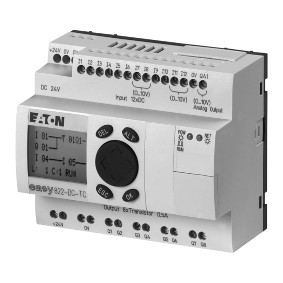
2 Installation 2.1 Mounting 800 2.1 Mounting 800 Install a easy800 device in an enclosure, switch cabinet or distribution board so that the power supply and terminal connections cannot be touched accidentally during operation. Snap the device onto an IEC/EN 60715 top-hat rail or fix it in place using fixing brackets. - Page 25 Figure 5: easy800 standard Figure 6: easy800-SWD ▶ Place the easy800 device diagonally on the upper lip of the top-hat rail. Press down lightly on both the device and the top-hat rail until the unit snaps over the lower edge of the top-hat rail.
-
Page 26: Mounting The Expansion Unit
2.2 Mounting the expansion unit To increase the number of inputs/outputs, you can connect an expansion unit via the easyLink connection of the easy800 standard. easy800-SWD devices are not provided with an easyLink terminal. Fit the expansion units in exactly the same way as a basic device on the top-hat rail or by screwing on fixing brackets. - Page 27 Figure 11:Screw fixing Locally and remotely connected expansion units have a different connection. Local expansion module Local expansion modules are connected directly next to the easy800 standard with easyLink connection. ▶ Connect the easy expansion unit via the EASY-LINK-DS bus connector plug.
- Page 28 Specific system information is shown in the status display of the easy800 standard (e.g. DC, AC or GW) depending on the expansion unit that is connected and ready for operation.
- Page 29 Figure 14:Connecting remote expansion module → Terminals E+ and E– of the EASY200-EASY are protected against short-circuits and polarity reversal. Functionality is only ensured if E+ is connected with E+ and E– with E–. Control Relay easy800 11/11 MN04902001Z-EN www.eaton.com...
-
Page 30: Terminations
The devices run a system test after the supply voltage has been switched on. On easy800 standard, this system test lasts 1 s. After this time RUN or STOP mode are activated - depending on the device and preset. On easy800-SWD the system test lasts at least 5.6 s. - Page 31 The relevant connection data for the different device types → section 12.3.3, “Power supply”, page 346. AC-800 standard 115/230 V Figure 15:Power supply on easy800 standard AC version DANGER Ensure that the L and N conductor are not reversed.
- Page 32 Figure 17:Power supply on the DC basic device easy800 standard 800 SWD The device and SmartWire-DT power supply is implemented via the POW terminals. On easy800-SWD provide cable protection (F1) rated for at least 3 A (slow). Loads such as contactors, circuit-breakers or motor-protective circuit- breakers can be fed with power via the AUX terminals.
- Page 33 802: I = 400 mA 806: I = 700 mA Figure 18:Power supply at easy800-SWD → easy800 standard DC version, the expansion units as well as easy800-SWD are protected against reverse polarity. DC expansion unit EASY…-DC-.E L01+ L01- 24 V H Figure 19:Power supply on the DC expansion unit Control Relay easy800 11/11 MN04902001Z-EN www.eaton.com...
-
Page 34: Connecting The Inputs
Example: With the “high-speed counter” function block, the device inputs I1 - I4 are connected directly on one function block. You can increase the number of inputs of the easy800 standard by using an expansion unit. The inputs of the EASY4..-DC-.E and EASY6..-DC-.E digital expansion units are detected by the easy800 standard automatically - without any configuration. -
Page 35: Connecting The Digital Inputs
Connecting AC inputs of the expansion unit EASY618-AC-RE E+ E– R11 R12 115/230 V h Figure 22:Connecting inputs on the easy618-AC-RE AC expansion unit Connect the inputs, for example, to pushbutton actuators, switches or relay/contactor contacts. Control Relay easy800 11/11 MN04902001Z-EN www.eaton.com... - Page 36 Always use neon lamps that are operated with a separate N connection. WARNING Do not use any Reed contacts at the I7 and I8 inputs. These may burn or melt due to the high inrush current of I7, I8. Control Relay easy800 11/11 MN04902001Z-EN www.eaton.com...
- Page 37 The following input circuit can be used in order to prevent interference and also when using two-wire proximity switches: 100 nF/275 V h 115/230 V h Figure 24:Increasing the input current on the easy800 standard AC version 100 nF/275 V h E+ E– R11 R12...
- Page 38 2 Installation 2.5 Connecting the inputs 100 nF/275 V h 1 kO 115/230 V h Figure 26:Limitation of the input current with a resistor at the AC easy800 standard 1 kO 100 nF/275 V h E+ E– R11 R12 115/230 V h...
- Page 39 The increased capacitance increases the drop out delay by approx. 40 ms. Use input terminals I1 to I12 of the DC easy800 standard to connect pushbutton actuators, switches or 3- or 4-wire proximity switches. Given the high residual current, do not use 2-wire proximity switches.
- Page 40 2.5 Connecting the inputs L01+ L01- ...V Figure 30:Application example with easy800 standard DC version Connect easy-DC inputs EASY806-DC-SWD Use input terminals I1 to I4 of EASY806-DC-SWD to connect pushbutton actuators, switches or 3- or 4-wire proximity switches. Given the high residual current, do not use 2-wire proximity switches.
- Page 41 2.5 Connecting the inputs Connecting high-speed counters and frequency generators With the easy800 standard DC version and with EASY806-DC-SWD, you can accurately measure high-speed counter signals or frequencies on digital inputs I1 - I4 independently of (i.e. bypassing) the cycle time.
- Page 42 2.5 Connecting the inputs Connecting incremental encoders The easy800 standard DC version and EASY806-DC-SWD allow you to connect an incremental encoder to each of the digital inputs I1, I2, I3 and I4. This enables you to count high-speed incremental values independently of the cycle time.
- Page 43 Current and temperature inputs cannot be used as digital inputs. Further information on the voltage range and input current of the input signals → section , “Connecting the DC inputs of the 800 standard”, page 35. Control Relay easy800 11/11 MN04902001Z-EN www.eaton.com...
-
Page 44: Connecting Analog Inputs
▶ With short cable lengths ground the shield of the signal cables at both ends with a large surface area connection. With longer signal cables, the shield should only be grounded at one end, on the side of the easy800 standard or expansion unit. Otherwise compensation currents between both grounding points may flow, leading to the interference of analog signals. - Page 45 Ensure that the reference potential is galvanically connected. Connect the 0 V of the power supply unit for the different setpoint potentiometers and sensors shown in the examples to the 0 V terminal of the easy800 standard power supply. Setpoint potentiometer +12 V...
- Page 46 The EASY4..-DC-ME DC expansion units convert analog input and output values with a 10-bit resolution (0 - 1023). When a Pt100 sensor is connected, the DC expansion units operate in the range between -50 °C and 200 °C. Control Relay easy800 11/11 MN04902001Z-EN www.eaton.com...
- Page 47 For voltage measuring, connect the output of the sensor to the voltage input (terminal 2 or 7), → section Figure 39:, “Setpoint potentiometer with upstream resistor”, page 41. Control Relay easy800 11/11 MN04902001Z-EN www.eaton.com...
-
Page 48: Connecting Outputs
0 V of the DC power supply of the expansion unit. 2.6 Connecting outputs Devices either have transistor outputs or relay outputs. easy800 standard outputs: The Q… outputs of both device versions are potentially isolated from the power supply and the inputs and therefore potential-free. - Page 49 • “Connect analog output“, Page 50. The number of outputs of the easy800 standard can be increased by using an expansion unit. The outputs of the EASY202-RE, EASY4..-DC-.E and EASY6..- DC-. digital expansion units are detected by the easy800 standard automatically - without any configuration.
-
Page 50: Connect Relay Outputs
Do not exceed the maximum voltage of 250 V AC on a relay contact. If the voltage exceeds this threshold, flashover may occur at the contact, resulting in damage to the device or a connected load. Control Relay easy800 11/11 MN04902001Z-EN www.eaton.com... - Page 51 L1, L2, L3 (115/230 Vh) + 24 V H + 24 V H Figure 47:Relay outputs EASY2..-RE Unlike the connection of the inputs, you can connect different phase conductors to the relay outputs of the EASY819-..-R.., EASY6..-..RE devices. Control Relay easy800 11/11 MN04902001Z-EN www.eaton.com...
-
Page 52: Connecting Transistor Outputs
2 Installation 2.6 Connecting outputs 2.6.2 Connecting transistor outputs The transistor outputs of easy800 standard must be provided with a suppressor circuit. The suppressor circuit is optional for easy800-SWD. Suppressor circuit of the transistor outputs for easy800 standard The switching off of inductive loads can produce high currents. Transistor outputs should be protected from this with a suppressor circuit. - Page 53 → Power the transistor outputs with voltage! Connect transistor outputs EASY806-DC-SWD Q1 Q2 24 V ⎓ 0.1 A 0.1 A 1.2 W/24 V ⎓ 0 V ⎓ +24 V ⎓ Figure 50:Transistor outputs EASY806-DC-SWD Control Relay easy800 11/11 MN04902001Z-EN www.eaton.com...
-
Page 54: Connect Analog Output
EASY6... -DC-TE 2.6.3 Connect analog output All easy800 standard devices with a 24 V DC supply voltage have an analog output QA 01. QA 01 can be used to output a DC voltage from 0 - 10 V, with a 10-bit resolution, value range 0 - 1023. - Page 55 EASY411-DC-ME two additional analog outputs. Both devices provide a DC voltage of 0 - 10 V with a 10-bit resolution and 0 - 1023 value range. Connect the actuator(s) to QA1(/QA2) and to the relevant 0 V terminal to its (their) left. Control Relay easy800 11/11 MN04902001Z-EN www.eaton.com...
- Page 56 Analog output QA1 (EASY406-DC-ME/EASY411-DC-ME), 0 - 10 V, b Analog output QA2 (only EASY411-DC-ME), 0 - 10 V. → Then configure the analog inputs/outputs you have connected, → Section “Configuring the analog expansion unit“, Page 84. Control Relay easy800 11/11 MN04902001Z-EN www.eaton.com...
-
Page 57: Net Network
0.3 m. Otherwise communication via easyNET may be impaired. When using the EASY223-SWIRE gateway, you cannot use any spur lines as the device cannot be addressed individually due to the lack of a serial interface. Control Relay easy800 11/11 MN04902001Z-EN www.eaton.com... - Page 58 I 1 - 12 Q 1 - 6 I 1 - 12 Q 1 - 8 Figure 55:Example of loop-through wiring of easy800 standard a First station on the easyNet b Bus termination resistor c Last station on the EasyNET network...
- Page 59 1 here. Accordingly, the bus termination resistor is connected to socket 2 of the last easyNet station. Value: 124 Ω • • Terminating connector: EASY-NT-R Control Relay easy800 11/11 MN04902001Z-EN www.eaton.com...
- Page 60 2.7 NET network Fitting and removing the Net connection cable ▶ With easy800 standard you must first remove the cover plate. Both RJ45 interfaces become visible. ▶ Plug in the cable; it must snap into the socket with an audible click ▶...
- Page 61 Data cable ECAN_L Ground cable GND (Ground) Selection cable SEL (IN/OUT) → The most basic easyNet configuration operates with the cables ECAN_H, ECAN_L, GND. The selection cable is only used for automatic addressing and configuration. Control Relay easy800 11/11 MN04902001Z-EN www.eaton.com...
- Page 62 Example 2: Physical location is not the same as the station number (apart from location 1 being the same as station 1). → Physical location 1 is always assigned as station 1. Station 1 is the only station which must be present. Control Relay easy800 11/11 MN04902001Z-EN www.eaton.com...
-
Page 63: Cable Length With Cross-Sections
Baud Rate Cable resistance R Kbit/s Ω 10 - 125 500, 1000 = Maximum cable length in m. = Total cable resistance in Ω. = Cable resistance per unit length in Ω/m. R’ R’ Control Relay easy800 11/11 MN04902001Z-EN www.eaton.com... -
Page 64: Connecting The Serial Interface
12.4 ρ 2.8 Connecting the serial interface Each easy800 device is provided on the front with a serial interface. The interface on easy800 standard is factory shipped with a protective cover fitted. Remove this cover carefully. The serial interface is used for: •... -
Page 65: Connection To A Pc
2.8.1 Connection to a PC Connect one of the following programming cables to the COM or USB interface of your PC and to the serial interface of the easy800 device. Table 3: Programming cable for the connection to a PC... -
Page 66: Connection To A Modem
2.8 Connecting the serial interface 2.8.2 Connection to a modem To set up a connection via modems connect a standard modem to the COM port of your PC and one to the serial interface of the easy800 standard device. Modem parameter assignment •... -
Page 67: Connecting For Point-To-Point Communication
In order ensure compliance with EMC requirements, the MFD-800-CAB5 cable must not be lengthened. Connecting example 800 standard to MFD-…-CP8/CP10 Figure 61:Fitting/removing the interface cover ▶ Remove the cover from the serial interface and connect the connector plug of the MFD-800-CAB5. Control Relay easy800 11/11 MN04902001Z-EN www.eaton.com... - Page 68 Connecting example 800-SWD to MFD-CP4 easy800-SWD devices are not provided with an operator keypad and display. In order to operate easy800-SWD directly, connect an MFD-CP4. For this use the EU4A-RJ45-CAB2 cable and observe the following terminal assignments: Control Relay easy800 11/11 MN04902001Z-EN www.eaton.com...
- Page 69 ▶ Use the EU4A-RJ45-CAB2 cable. ▶ Insert the cables into the push-in terminals of the MFD-CP4 according to the terminal assignment → Table 6. ▶ Insert the RJ45 plug into the serial interface of the easy800-SWD device. EU4A-RJ45-CAB2 EU4A-RJ45-CAB2 MFD-CP4 easy800-SWD Control Relay easy800 11/11 MN04902001Z-EN www.eaton.com...
-
Page 70: Inserting The Memory Card
2.8 Connecting the serial interface 2.8.4 Inserting the memory card easy800 standard devices support the use of memory cards that are fitted into the serial interface. The memory card can be used to store a single program that can be read from any suitable easy800 standard device. -
Page 71: Install Smartwire-Dt
2 Installation 2.9 Install SmartWire-DT 2.9 Install SmartWire-DT SmartWire-DT is only supported by easy800-SWD devices. Connection SmartWire-DT Warning SWD stations may be destroyed if they are refitted in the SWD line when the power supply is on. Switch off the power supply beforehand. - Page 72 2 Installation 2.9 Install SmartWire-DT Potential isolation SmartWire-DT is galvanically isolated from: • • • easyNet SmartWire-DT is galvanically connected to: • • Inputs • Outputs Control Relay easy800 11/11 MN04902001Z-EN www.eaton.com...
-
Page 73: Commissioning
The easy800 devices without display and operator functions can be commissioned. However, a display and operating facility is required in order to follow all explanations in this chapter. If you are operating an easy800, you can connect via a point-to-point connection or easyNet display and operating units. -
Page 74: Setting The Menu Language
RUN mode. 3.2 Setting the menu language When you switch on the easy800 device for the first time, you will be asked to select the menu language. ▶ Use the cursor buttons Í... -
Page 75: Led Display
3 Commissioning 3.3 LED display 3.3 LED display The following LEDs are provided on the front of the easy800 depending on device type: 1. POW/RUN 2. NET 3. Config (only easy800-SWD) 4. SWD (only easy800-SWD). LED POW/RUN The POW/RUN LED indicates the state of the POW power supply as well as the RUN or STOP operating mode. -
Page 76: Status Display
After power on, the easy800 shows the status display of the basic device. The status display has four lines. If a local expansion is connected to easy800 standard, press OK to show the status display of the local expansion in the display (→... - Page 77 NET stations“, Page 97). Status display of the local expansion Press OK to move from the Status display for the easy800 standard to the Status display for the local expansion unit if this is being operated via the easyLink connection.
-
Page 78: Choosing The Main And System Menu
GW flashes: Only EASY200-EASY, but no connected I/O expansion. : When the power supply is switched on, the easy800 switches to STOP operating mode How to show the status display of other NET stations is described in →... -
Page 79: Operating Principle In The Circuit Diagram And Function Block Editor
NET-ID. Use OK to switch to Entry mode so that you can enter or change a value at the current cursor position. Press ESC in Entry mode to restore easy800 to the last changes of an entry. -
Page 80: Defining 800-Swd Inputs/Outputs
Be aware that certain function blocks may not be available with certain configurations. For example, output Q2 is permanently associated with PO01. If Q2 is configured as an input, PO01 is no longer available. Control Relay easy800 11/11 MN04902001Z-EN www.eaton.com... -
Page 81: Operating Modes
Create your circuit diagram so that a defined and safe startup procedure is always provided after the power supply is switched The easy800 standard device with an integrated display does not start with RUN mode if you deactivate the RUN MODE startup behavior. -
Page 82: The First Circuit Diagram
As with conventional wiring, you use contacts and relays in the diagram. The easy800 device saves you having to use and wire different components. At the push of a few buttons, the easy800 circuit diagram produces all the wiring required. All you have to do is then connect any switches, sensors, lamps or contactors you wish to use. -
Page 83: Draw A Wiring Diagram
Each line is a circuit connection. easy800 automatically connects ÊÊÊÊÊÊÊ-ÊÊÊÊÊÊÊ- the contact to the power supply. L: 1 C:1 B:7944 The following example is provided for a lighting control. The easy800 device takes on the wiring and the tasks of the circuit shown below. L01+ L01 + L01 –... - Page 84 3 Commissioning 3.8 The first circuit diagram From the first contact to the output coil With easy800 devices wire from the input to the output. The first input contact is ▶ Press OK. easy800 proposes the first contact at the cursor position.
- Page 85 ÊÊÊÊÊÊÊ-ÊÊÊÊÊÊÊ- → L: 1 C:1 B:7944 The easy800 device automatically connects adjacent contacts up to the coil. ▶ Press ALT to wire the cursor from through to the coil field. The cursor changes into a flashing wiring arrow and automatically jumps to -I02 the next logical wiring position.
-
Page 86: Testing The Circuit Diagram
Test using the power flow display ▶ Change to the circuit diagram display and press pushbutton S1. The relay picks up and the easy800 displays the power flow with a double line. I01====I02====================Ä Q01 L: 1 C:1 RUN... - Page 87 → The circuit diagram does not have to be completed in its entirety so that it is possible to test parts of it. The easy800 device simply ignores any incomplete wiring that is not yet working and only uses the finished wiring.
-
Page 88: Delete Program
NET parameterization. Proceed as follows to delete the program in the easy800 device: ▶ easy800 must be in STOP mode in order to extend, delete or modify the circuit diagram. Switch the easy800 device to STOP mode. - Page 89 (analog input 1 to 6 as well as analog output 1 and 2). Marker words MW89 - MW96 are therefore assigned (→ Table 9, Page 87). With EASY411-DC-ME you can activate and commission all six analog inputs (voltage, current or temperature) at the same time. Control Relay easy800 11/11 MN04902001Z-EN www.eaton.com...
-
Page 90: Setting Device Parameters For The Expansion Unit
Both devices must be connected to the power supply and mounted. • easy800 standard must be in STOP mode and the Status display must be showing. They are processed in the program using marker words, → Table 9 Page 87. - Page 91 3.9 Configuring the analog expansion unit → The parameters configured here are stored retentively and only in the expansion unit, not in the easy800 standard. This means: You must complete this configuration again when exchanging a configurable expansion unit. Processing analog input/output values You access the now configured analog input/output values via marker words (MW).
- Page 92 A 01Q1-------------------------Ä Q 01 A 01CY-------------------------S Q 02 Parameter setting of the “analog value comparison” function block A 01 EQ + >I1 >F1 +2 >I2 MW93 >F2 +10 >OS >HY Control Relay easy800 11/11 MN04902001Z-EN www.eaton.com...
- Page 93 Wire breakage on at least one PT100 input for temperature measuring. The fault message can only appear with PT100 measuring activated. Short-circuit at analog output 0 - 10 V. Short-circuit at one or more digital outputs. Control Relay easy800 11/11 MN04902001Z-EN www.eaton.com...
-
Page 94: Commissioning An Net Network
NET, the station with NET ID 1. This NET station can be used to configure the entire NET. You should only configure the individual device locally in the following cases: • When exchanging devices • When connecting an EC4P to easy800 standard Control Relay easy800 11/11 MN04902001Z-EN www.eaton.com... -
Page 95: Parameterizing Net Stations
3 Commissioning 3.10 Commissioning an Net network 3.10.1 Parameterizing NET stations Requirement: The easy800 device must be in STOP operating mode. Figure 80: I....The Status display is active and you move as follows to the NET Parameters MO 02:00 menu: ▶... - Page 96 NET-IDs. Æ æ NET-ID geographical position of the device on the network. Figure 81: Requirement: The easy800 device must be in STOP operating mode. NET-PARAMETER... You must be in the NET-PARAMETER menu. STATIONS... CONFIGURE... ▶ Use the Í...
- Page 97 Tip: Carry out a NET configuration through NET station 1 after every change to the NET. If your NET configuration does not function as required you will find a description of possible causes in → section “Functionality of the NET faulty”, page 337. Control Relay easy800 11/11 MN04902001Z-EN www.eaton.com...
-
Page 98: Configuring Net
Furthermore, all devices are automatically set with the baud rate and bus delay time set on NET station 1. Carry out this configuration in the CONFIGURE menu. You can only configure the NET network by entering settings on the NET station 1. Control Relay easy800 11/11 MN04902001Z-EN www.eaton.com... - Page 99 Procedure ▶ Proceed to the CONFIGURE menu item and press the OK pushbutton. NET-PARAMETER... STATIONS... You will be asked to acknowledge whether you want to configure the CONFIGURE system. ▶ Press OK. CONFIGURE? Control Relay easy800 11/11 MN04902001Z-EN www.eaton.com...
- Page 100 If you wish to correct the NET ID ( → section “Change station list”, page ERR: ID 93), confirm the prompt with OK. Otherwise you can cancel the configuration CONFLICT with ESC. CONFIGURATION Control Relay easy800 11/11 MN04902001Z-EN www.eaton.com...
-
Page 101: Deleting The Program Of A Net Station
If you delete the program in NET station 1, the NET configuration managed by this station is also deleted. The project configuration is also deleted with easy800-SWD. The target configuration is retained. Solution for the accidental deletion of the NET configuration •... -
Page 102: Putting The Smartwire-Dt Into Operation
Config. LED: off • The SWD status LEDs on the SWD stations also flash green. ▶ Press the Config configuration button on easy800-SWD for at least 2 s. The status of the LEDs on the device is as follows: •... - Page 103 All stations are addressed consecutively in ascending order. The physically present actual configuration is determined on the SWD line. This is stored in easy800-SWD retentively as the target configuration. The SWD-LED indicates with a green continuous light that the target configuration matches the actual configuration.
- Page 104 3 Commissioning 3.11 Putting the SmartWire-DT into operation Control Relay easy800 11/11 MN04902001Z-EN www.eaton.com...
-
Page 105: Wiring With 800
4.1 Circuit diagram display You wire contacts and coils of relays in the easy800 circuit diagram from left I 01----I 02--u to right, from the contact to the coil. The circuit diagram is created on a Q 01----HY01Q1k hidden wiring grid containing contact fields, coil fields and rungs. -
Page 106: Program
It is used in RUN mode to check the circuit diagram using the power flow display. 4.2 Program An easy800 program consists of the necessary settings for the device, easyNet, password, system settings and operating parameters and the following components: •... -
Page 107: Loading A Program On The 800-Swd Device
SmartWire-DT was installed and is therefore identical. 4.4 Circuit diagram elements A circuit diagram is a series of commands that the easy800 device processes cyclically in RUN operating mode. Coils and contacts are interconnected in the circuit diagram. In RUN mode, a coil is switched on or off depending on the power flow and coil function set. -
Page 108: Relays
Contacts such as N/O contacts are set to 1 when they are closed and 0 when they are opened. In the easy800 circuit diagram you can wire contacts as make or break contacts. N/C contacts are indicated with a horizontal line above the operand concerned. - Page 109 Figure 84:Contactor function signal diagram Coil with the impulse relay function ä The relay coil switches whenever the input signal changes from 0 to 1. The relay behaves like a bistable flip-flop. Figure 85:Impulse relay signal diagram Control Relay easy800 11/11 MN04902001Z-EN www.eaton.com...
- Page 110 The output signal follows the inverted input signal, the relay works like a contactor with negated contacts. If the coil is set to 1, the coil will switch its make contacts to 0. Figure 88:Inverse contactor function signal diagram Control Relay easy800 11/11 MN04902001Z-EN www.eaton.com...
-
Page 111: Markers And Analog Operands
Boolean states 0 or 1. A marker bit is also called an auxiliary relay. easy800 devices also manage the marker bits in marker bytes (MB), marker words (MW) and in marker double words (MD). A marker byte consists of 8 marker bits, a marker word of 16 marker bits and a marker double word of 32 marker bits. - Page 112 Marker bit (M), marker bytes (MB), marker words (MW) and marker double words (MD) are used in the circuit and function block diagram. Expansion units for analog value measuring can be used on easy800 standard devices from device version number 04. The analog inputs and...
- Page 113 M32, the last write operation is retained. → Tip: Observing the following wiring rules will prevent the double assignment of marker bits. • For easy800 standard with the marker bits M01-M96 use • Marker bytes, starting at MB13 • Marker words, starting at MW07 •...
- Page 114 The easy800 device processes calculations with a signed 31-bit value. The value range is: –2147483648 to +2147483647 With a 31-bit value, the 32nd bit is the sign bit.
-
Page 115: Working With Contacts And Coils
The following describes how you wire the different contacts and coils of different relay types or function blocks (inputs) in the circuit diagram. 4.5.1 Entering and changing contacts You choose an input contact in the easy800 device by means of the contact I 02 name and the contact number. -
Page 116: Changing N/O Contacts To N/C Contacts
Persons, systems and machine may be put at risk if an N/C contact is misinterpreted. When using N/C contacts in the program of easy800-SWD always evaluate the PRSNT and DIAG diagnostic bits of this station. You can define each contact in the circuit diagram as a N/O or N/C. -
Page 117: Entering And Changing Coils
OK to move to the next position (a selected position is shown in light grey in the following figure). ▶ Use ÍÚ to modify the value of the position. Control Relay easy800 11/11 MN04902001Z-EN www.eaton.com... -
Page 118: Deleting Contacts And Coils
4 Wiring with 800 4.5 Working with contacts and coils The easy800 device closes entry mode as soon as you leave a contact or coil ú í field with or OK. In the contact field to change In the coil field change I 01 Ä... -
Page 119: Deleting Connections
4.5.7 Insert Rung The circuit diagram display shows three of the 256 rungs at the same time. Rungs outside of the display, including empty rungs, are scrolled by easy800 automatically in the circuit diagram display if you move the cursor beyond the top or bottom of the display. -
Page 120: Delete Rung
4.5 Working with contacts and coils 4.5.8 Delete Rung The easy800 device only removes empty rungs (without contacts or coils). ▶ Delete all contacts and coils from the rung. ▶ Position the cursor on the first contact field of the empty rung. -
Page 121: Aborting Circuit Diagram Entry
4.5.13 Switching with the Cursor Buttons With an easy800 device, you can also use the four cursor buttons as hard- wired inputs in the circuit diagram. The P buttons can also be used for testing circuits or manual mode. These button functions are also useful for servicing and commissioning purposes. -
Page 122: Checking The Circuit Diagram
I 02--u------------------------S Q 01 I 03--k Figure 97:Parallel connection ▶ Switch the easy800 to the operating mode RUN via the main menu. ▶ Return to the circuit diagram display. You are now unable to edit the circuit diagram. Control Relay easy800 11/11 MN04902001Z-EN www.eaton.com... -
Page 123: Jumps
“Function blocks”→ section 5.19, “LB, jump label”, page 213 and → section 5.18, “JC, conditional jump”, page 211. The easy800 device allows the use of up to 32 jumps. Circuit diagram elements for jumps in the circuit diagram Contact (N/O... - Page 124 → Backward jumps cannot be executed due to the way in which easy800 works. If the jump label does not come after the jump coil, the jump will be made to the end of the circuit diagram. The last rung is also skipped.
-
Page 125: Wiring Net Operands In The Circuit Diagram
Wiring a contact or coil of another NET station in the circuit diagram Requirement: You must have selected an I.., R.., Q.., R.., RN.. S.. or SN.. operand in the circuit diagram and Entry mode must have been selected. Control Relay easy800 11/11 MN04902001Z-EN www.eaton.com... - Page 126 • Put (PT) and Get (GT) are used in order to exchange double word operands via the NET. More information about the function blocks → section 5, “Function blocks”, page 135. Control Relay easy800 11/11 MN04902001Z-EN www.eaton.com...
- Page 127 The function blocks are of data type 32-bit. They only function if the NET is operating correctly (→ section 10, “Diagnostics possibilities”, page 329). More information about the function blocks → section 5, “Function blocks”, page 135. Control Relay easy800 11/11 MN04902001Z-EN www.eaton.com...
-
Page 128: Program Transfer From And To The Memory Card
4.6 Program transfer from and to the memory card A program with all the necessary parameters can be loaded from the memory card into the easy800 standard device or written from the device to the card. Information stored on the memory card is “non-volatile” and thus you can use the card to archive, transfer and copy circuit diagrams. - Page 129 The storing device saved its type and version on the card. A program to be loaded from the card must be suitable for the destination device, otherwise this will refuse the transfer and a program in the easy800 device will be retained (→ section 4.6.2, “Program exchange between devices with memory card”, page 126)
-
Page 130: Deleting A Program On The Card
The easy800 standard device family allows programs from an older version to be read in newer device versions without any restrictions in function. A memory card with a program can always be read by an easy800 standard device that has a newer operating system (with a higher version number) than the device from which the memory card was written. -
Page 131: Working With Function Blocks
With easy800 standard you can insert up to 255 function blocks in the function block list and with easy800-SWD 256 function blocks. - Page 132 ▶ Press ESC in order to save the circuit diagram with the newly added function block. ▶ Answer the subsequent SAVE prompt with OK. The circuit diagram is saved and the easy800 device changes to the next higher menu level. How to carry out the complete parameterization is described in →...
-
Page 133: Function Block List
T 01 ?X M:S + >I1 20:30 Variable, operand for Function block inputs >I2 inputs Function block outputs QV> MD96 Variable, operand for outputs Figure 101:Display of the function blocks in the function block editor Control Relay easy800 11/11 MN04902001Z-EN www.eaton.com... - Page 134 If, for example, the T timing relay function block is triggered with a negative time setpoint, it will no longer switch in the expected way. You should therefore take care to exclude such situations, as the easy800 device cannot foresee these when the parameters are assigned.
- Page 135 • >I2 = Constant 1095. • QV> = Marker double word MD56 AR01 ADD AR01 ADD >I1 C 01QV> >I1 20056 >I2 1095 >I2 1095 QV> MD 56 QV> 21151 Setpoint values Actual values Control Relay easy800 11/11 MN04902001Z-EN www.eaton.com...
-
Page 136: Parameters Menu
To remove a function block, you must remove it from the circuit diagram and from the function block list. Requirement: The easy800 device must be in STOP operating mode. ▶ Press OK -> PROGRAM->PROGRAM>CIRCUIT DIAGRAM to enter the circuit diagram display from the Status display. - Page 137 • Current actual values are deleted when you switch off the power supply or switch the easy800 device to STOP mode. Exception: Retentive data keeps its state (→ section 8.2.6, “Retentive data storage”, page 308,). The most recent actual values are transferred to the operands every cycle.
- Page 138 4 Wiring with 800 4.7 Working with function blocks Control Relay easy800 11/11 MN04902001Z-EN www.eaton.com...
-
Page 139: Function Blocks
Parameter set is accessible via PARAMETERS men u The default setting of this parameter is +. Not all easy800 have all function blocks. Information on this is provided in the relevant function block description. Control Relay easy800 11/11 MN04902001Z-EN www.eaton.com... -
Page 140: A, Analog Value Comparator/Threshold Value Switch
An analog value comparator or threshold value switch is used, for example, to compare analog values or marker contents and switch when defined threshold values are reached. easy800 allows the use of up to 32 analog value comparators/threshold switches. Contacts and Coils... - Page 141 Analog output QA01. • Output QV of a different function block … If they are not associated, the inputs have a default value of: • F1 and F2 = 1 • OS and HY = 0 Control Relay easy800 11/11 MN04902001Z-EN www.eaton.com...
- Page 142 – The contact switches if the actual value reaches the setpoint value. – The actual value changes and rises above the value of the setpoint value plus hysteresis. – The contact goes to the normal position. Control Relay easy800 11/11 MN04902001Z-EN www.eaton.com...
- Page 143 CY opens as soon as I1 with offset is once more within the value range. Memory 68 + per 4 Byte/Constant at function block input Cycle time [μs] easy800 standard easy800-SWD Mode = INI/CPY Control Relay easy800 11/11 MN04902001Z-EN www.eaton.com...
-
Page 144: Ar, Arithmetic
• Divide. easy800 allows the use of up to 32 arithmetic function blocks. An arithmetic function block does not require an enable or start signal and is therefore not wired in a coil field of the standard circuit diagram. The function... - Page 145 If the calculation result exceeds the value range that can be represented, the overflow signal contact CY closes and output QV contains the value of the last valid operation. When the function block is called for the first time, the value at output QV equals zero. Control Relay easy800 11/11 MN04902001Z-EN www.eaton.com...
- Page 146 1024 : 0 = Last valid value before this arithmetic operation, due to overflow (CARRY) (mathematically correct “Infinity”) AR..CY = Status 1 • -1000 : 10 = -100 • 1000 : (-10) = -100 • -1000 : (-10) = 100 • 10 : 100 = 0 Control Relay easy800 11/11 MN04902001Z-EN www.eaton.com...
-
Page 147: Bc, Data Block Comparator
5.3 BC, data block comparator 5.3 BC, data block comparator This function block is available for easy800-SWD from device version 01 and for easy800 standard devices from device version 04. The data block comparator (BC = Block Compare) function block compares two contiguous marker ranges. - Page 148 (e.g. MB380) that you cannot address when using marker operands (direct addressing). Offset calculation for addressing marker words: Offset = MW (x - 1) x 2 Offset calculation for addressing marker double words: Offset = MD (x - 1) x 4 Control Relay easy800 11/11 MN04902001Z-EN www.eaton.com...
- Page 149 1 (decimal) 2 (decimal) MB10 MB40 MB11 MB41 MB12 MB42 MB13 MB43 MB14 MB44 The comparison result of the function block BC01 is: BC01EQ = 1, the data block ranges have the same content. Control Relay easy800 11/11 MN04902001Z-EN www.eaton.com...
- Page 150 Comparison range 1: MB60 • Comparison range 2: MD80 • Number of bytes: → The comparison is in byte format. MD80 has 4 bytes. Therefore the first two bytes of MD81 are also compared. Control Relay easy800 11/11 MN04902001Z-EN www.eaton.com...
- Page 151 The comparison is in byte format. MD90 to MD96 is 28 bytes. The number of bytes is 30 bytes. The error message “Number of comparison elements exceeds one of the comparison ranges” is output. BC01E1 is 1. Control Relay easy800 11/11 MN04902001Z-EN www.eaton.com...
- Page 152 The value of C 01QV is 1024. This value is too big. The value at >NO can be between 1 and +383. The error message “The specified offset of the comparison ranges is outside of the permissible range” is output. BC01E3 is 1. Control Relay easy800 11/11 MN04902001Z-EN www.eaton.com...
-
Page 153: Bt, Data Block Transformer
(data initialization). The following marker ranges can be transferred and written: • • • easy800 device allows the use of up to 32 data block transfer function blocks. Contacts and Coils Contacts Meaning Outside of source or destination range BT..E1... - Page 154 Marker range with offset If you wish to work with an offset, specify one of the following variables at function block input I1 or I2. • Analog input IA.. • Analog output QA.. Control Relay easy800 11/11 MN04902001Z-EN www.eaton.com...
- Page 155 Mode=INI/CPY 1 Byte 10 Bytes 100 Bytes Example 1: Initializing marker blocks, direct definition marker ranges The value of marker byte 10 is to be transferred to marker bytes 20 to 24. Control Relay easy800 11/11 MN04902001Z-EN www.eaton.com...
- Page 156 (decimal) (decimal) MB15 MB65 MB66 MB67 MB68 After a rising edge from 0 to 1 at coil BT01T_ the value 45 is present in the marker bytes MB65 to MB68. Control Relay easy800 11/11 MN04902001Z-EN www.eaton.com...
- Page 157 757935405/ (Byte 3) 00101100010110110010110100101101 MD81 757935405/ (Byte 4, MSB) 00101101001011010010110100101101 After a rising edge from 0 to 1 at coil BT01T_ the value 757935405 is present in the marker double words MD80 and MD81. Control Relay easy800 11/11 MN04902001Z-EN www.eaton.com...
- Page 158 The value of C 01QV is 788. This value is too big. The value at >NO can be between 1 and +192. The message “The specified offset of the destination range is outside of the permissible range” is output. BT01E3 is 1. Control Relay easy800 11/11 MN04902001Z-EN www.eaton.com...
- Page 159 MB11 MB21 MB12 MB22 MB13 MB23 MB14 MB24 After a rising edge from 0 to 1 at coil BT01T_ the content of MB10 to MB14 is copied to the marker bytes MB20 to MB24. Control Relay easy800 11/11 MN04902001Z-EN www.eaton.com...
- Page 160 • Number of bytes: → The transfer is in byte format. 12 bytes are to be copied. The range MD60 to MD62 is 12 bytes. This is copied to the range MW40 to MW45. Control Relay easy800 11/11 MN04902001Z-EN www.eaton.com...
- Page 161 The transfer is in byte format. MD93 to MD96 is 16 bytes. 18 bytes were incorrectly defined as length. The error message “Number of elements exceeds the destination range” is output. BT01E1 is 1. Control Relay easy800 11/11 MN04902001Z-EN www.eaton.com...
- Page 162 The value of C 01QV is 10042. This value is too big. The value at >NO can be between 1 and +383. The message “The specified offset of the destination range is outside of the permissible range” is output. BT01E3 is 1. Control Relay easy800 11/11 MN04902001Z-EN www.eaton.com...
-
Page 163: Bv, Boolean Operation
• Masking out of particular bits from values, • Bit pattern recognition, • Bit pattern modification. easy800 device allows the use of up to 32 Boolean operations. Contacts and Coils Contacts Meaning Result at output QV> is zero BV..ZE Example of a function block for Boolean operation BV01ZE------------------------Ä... - Page 164 If you associate a negative value (e.g. -10 ) the central processing unit will form the two's complement of the amount. Example: Magnitude(-10 00000000000000000000000000001010 Binary Ones' complement formation 11111111111111111111111111110101 adding 1 Binary result 11111111111111111111111111110110 Hexadecimal result FFFFFFF6 Control Relay easy800 11/11 MN04902001Z-EN www.eaton.com...
- Page 165 The NOT sequence operates according to the following rules: I1, positive value Subtract value of I1 and 1: –|I1| – 1 = I2 I1, negative value Subtract value of I1 and 1: |I1| – 1 = I2 Control Relay easy800 11/11 MN04902001Z-EN www.eaton.com...
-
Page 166: C, Counter Relay
You can set a lower and higher limit setpoint as comparison values for the counter relay function block, as well as a start value. easy800 device allows the use of up to 32 counter relays. → Square wave count pulses are required to ensure a 1:1 mark to space ratio. - Page 167 Analog inputs IA01 to IA04: • IA01: Terminal I7. • IA02: Terminal I8. • IA03: Terminal I11. • IA04: Terminal I12. • Analog output QA01. • Output QV of a different function block. … Control Relay easy800 11/11 MN04902001Z-EN www.eaton.com...
- Page 168 If a counter relay is retentive, the actual value is retained when the operating mode changes from RUN to STOP as well as when the power supply is switched off. If easy800 is started in RUN operating mode, the counter relay operates with the retentively saved actual value.
- Page 169 – The contacts OF, FB, ZE become active according to the direction of the values (positive or negative). Memory 52 + per 4 Byte/Constant at function block input Cycle time [μs] easy800 standard easy800-SWD Control Relay easy800 11/11 MN04902001Z-EN www.eaton.com...
-
Page 170: Cf, Frequency Counter
I1, the function of the function block is activated by the device input I5. CF01OF-------------------------Ä Q 01 CF01FB-------------------------Ä Q 02 CF01ZE-------------------------Ä Q 03 Figure 114:Wiring the function block contacts The messages of the function block are sent directly to the device outputs. Control Relay easy800 11/11 MN04902001Z-EN www.eaton.com... - Page 171 You can assign the following operands to output … • Analog output QA01 • Markers MD, MW, MB Retention The frequency counter does not have any retentive actual values since the frequency is continuously remeasured. Control Relay easy800 11/11 MN04902001Z-EN www.eaton.com...
- Page 172 2: Upper setpoint value >SH 3: Lower setpoint value >SL 4: Enable CF..EN 5: Contact (N/O) CF..OF: Upper setpoint value exceeded 6: Contact (N/O) CF..FB: Lower setpoint value undershot 7: Actual value equal to zero CF..ZE Control Relay easy800 11/11 MN04902001Z-EN www.eaton.com...
-
Page 173: High-Speed Counter
Not picked up: down counting. Transfer of the start value on a rising edge. CH..SE High-speed counter example I 05---------------------------Ä CH03EN I 06---------------------------Ä CH03RE I 07---------------------------Ä CH03D_ I 08---------------------------Ä CH03SE Figure 116:Wiring the function block coils Control Relay easy800 11/11 MN04902001Z-EN www.eaton.com... - Page 174 Parameter set can be called via the PARAMETERS menu Upper setpoint: -2147483648 - 2147483647 >SH Lower setpoint: -2147483648 - 2147483647 >SL Start value (Preset): -2147483648 - 2147483647 >SV Actual value: -2147483648 - 2147483647 QV> Control Relay easy800 11/11 MN04902001Z-EN www.eaton.com...
- Page 175 If a meter is retentive, the actual value is retained when the operating mode changes from RUN to STOP as well as when the supply voltage is switched off. If a easy800 is started in RUN mode, the counter operates with the retentively saved actual value. Control Relay easy800 11/11 MN04902001Z-EN www.eaton.com...
- Page 176 The contact “upper setpoint value” CH…OF becomes active. • Range C: – The coil CH..SE is briefly actuated and the actual value is set to the start value. The contacts go to the respective position. Control Relay easy800 11/11 MN04902001Z-EN www.eaton.com...
- Page 177 – The contacts OF, FB, ZE become active according to the direction of the values (positive or negative). Memory 52 + per 4 Byte/Constant at function block input Cycle time [μs] easy800 standard easy800-SWD Control Relay easy800 11/11 MN04902001Z-EN www.eaton.com...
-
Page 178: Ci, High-Speed Incremental Value Counter
The signals of channels A and B must be offset by 90° otherwise the count direction will not be detected. The maximum counter frequency for easy800 standard is 3000 Hz and 5000 Hz for EASY806-DC-SWD. → Note that the digital inputs I1 to I4 are permanently assigned to the incremental counter function blocks provided: •... - Page 179 Analog inputs IA01 to IA04: • IA01: Terminal I7. • IA02: Terminal I8. • IA03: Terminal I11. • IA04: Terminal I12. • Analog output QA01. • Output QV of a different function block. … Control Relay easy800 11/11 MN04902001Z-EN www.eaton.com...
- Page 180 If a meter is retentive, the actual value is retained when the operating mode changes from RUN to STOP as well as when the supply voltage is switched off. If a easy800 is started in RUN mode, the counter operates with the retentively saved actual value. Function of the function block...
- Page 181 The “upper setpoint value reached” contact CI..OF becomes active. • Range C: – The coil CI..SE is briefly actuated and the actual value is set to the start value. The contacts go to the respective position. Control Relay easy800 11/11 MN04902001Z-EN www.eaton.com...
- Page 182 – The contact CI..ZE is active. • Range F: – The actual value goes outside the value range of the counter. – The contacts OF, FB, ZE become active according to the direction of the values (positive or negative). Control Relay easy800 11/11 MN04902001Z-EN www.eaton.com...
-
Page 183: Cp, Comparator
The following scans are possible: • I1 greater than I2. • I1 equal to I2. • I1 less than I2. easy800 device allows the use of up to 32 comparators. Contacts and Coils A closed contact indicates: Contacts Meaning >I1 less than >I2... - Page 184 I1 greater than I2, GT contact closes. • I1 equal to I2, EQ contact closes. • I1 less than I2, LT contact closes. Memory 32 + per 4 Byte/Constant at function block input Cycle time [μs] easy800 standard easy800-SWD Control Relay easy800 11/11 MN04902001Z-EN www.eaton.com...
-
Page 185: D, Text Display
A easy800 device allows the use of up to 32 function blocks for text display. The programming software easySoft-Pro is used for editing the individual text lines in the Parameters tab. - Page 186 The values of the analog inputs an outputs can be scaled. Area Selectable display range Example 0 - 10 V 0 - 9999 0000 - 0100 0 - 10 V ± 999 -025 - 050 0 - 10 V ± 9.9 -5.0 - 5.0 Control Relay easy800 11/11 MN04902001Z-EN www.eaton.com...
- Page 187 • STOP operating mode is selected. • The easy800 device is switched off. • A menu was selected via OK or DEL + ALT. D 02 to D 32: If several texts are present and are triggered, each text is automatically displayed in turn every 4 s.
- Page 188 FAILED! Figure 126:Text output examples Setpoint entry in a display This function is available for easy800-SWD from device version 01 and for easy800 standard from device version 04. → When values are being entered, the text is retained statically on the display.
-
Page 189: Db, Data Block
The function block stores values such as setpoints for function blocks. The value applied to input I1 is saved in the operand linked to output QV. easy800 device allows the use of up to 32 data function blocks. Contacts and Coils... - Page 190 36 + per 4 Byte/Constant at function block input Cycle time [μs] easy800 standard easy800-SWD Figure 129:Signal diagram of data function block 1: Value at input DB..>I1 2: Trigger coil DB…T_ 3: Value on DB…QV> Control Relay easy800 11/11 MN04902001Z-EN www.eaton.com...
-
Page 191: Dc, Pid Controller
5 Function blocks 5.13 DC, PID controller 5.13 DC, PID controller This function block is available for easy800-SWD from device version 01 and for easy800 standard devices from device version 04. 32 PID controllers are provided. DANGER A knowledge of closed-loop control is required in order to use the PID controllers. - Page 192 100 ms; Example: The value 20 is processed in the function block as 2 s. Scan Time T : 0 - 65535, in 100 ms >TC Manual manipulated variable: -4096 - +4095 >MV Manipulated variable: QV> • Unipolar: 0 - 4095 • Bipolar: -4096 - +4095 Control Relay easy800 11/11 MN04902001Z-EN www.eaton.com...
- Page 193 Analog inputs IA01 to IA04: • IA01: Terminal I7. • IA02: Terminal I8. • IA03: Terminal I11. • IA04: Terminal I12. • Analog output QA01. • Output QV of a different function block. … Control Relay easy800 11/11 MN04902001Z-EN www.eaton.com...
- Page 194 (t) = Actual value with scan time t Integral component The integral component Y is proportional to the sum of the control difference over time. The equation used by the device for the integral component is as follows: Control Relay easy800 11/11 MN04902001Z-EN www.eaton.com...
- Page 195 Extreme changes in the manipulated variable can occur when the manual manipulated variable is transferred or deactivated. → If the function block is running in UNI (unipolar) mode, a negative signed manipulated variable value will be output as the value zero. Control Relay easy800 11/11 MN04902001Z-EN www.eaton.com...
-
Page 196: Ft, Signal Smoothing Filter
5.14 FT, signal smoothing filter 5.14 FT, signal smoothing filter This function block is available for easy800-SWD from device version 01 and for easy800 standard devices from device version 04. The function block smoothes noisy signals such as analog input signals. It operates as a low pass filter. - Page 197 If the function block is called for the first time, the output value is initialized with the input value when the device is started or after a reset. This speeds up the startup behavior of the function block. Control Relay easy800 11/11 MN04902001Z-EN www.eaton.com...
- Page 198 Y(t–-1) = Output value with scan time t - 1 Scan time: Scan time T depends on the set recovery time value. Recovery time T Scan time T 0.1 s - 1 s 10 ms 1 s - 6553 s 0.01 T Control Relay easy800 11/11 MN04902001Z-EN www.eaton.com...
- Page 199 = 1, 2, 3, … The function block always operates with a scan time that corresponds to an integer multiple of the cycle time. This can cause the set recovery time to be lengthened. Control Relay easy800 11/11 MN04902001Z-EN www.eaton.com...
-
Page 200: Gt, Get Value From The Net
GT automatically fetches the data designated for itself as soon as it is provided on the NET by another NET station using PUT function block easy800 device allows the use of up to 32 GT function blocks. EASY802-DC-SWD is not provided for the function block. - Page 201 Figure 135:Signal diagram function block GT 1: GT..Q1 2: Value on GT..QV → The GT function block has the value 0 when the power supply is switched on. Memory 28 Byte Cycle time [μs] easy800 standard easy800-SWD Control Relay easy800 11/11 MN04902001Z-EN www.eaton.com...
-
Page 202: Hw, Weekly Timer
The procedure for setting the time, → Section “ Setting time and date“, Page 313. easy800 device allows for the use of up to 32 function blocks of type weekly timer. For each weekly timer four switch channels A, B, C and D are available. - Page 203 Display of the parameters: Channel D Day 1 and day 2 These parameters DY1/DY2 are used to limit the period in which the output HW..Q1 is switched. Enter either a period of several days or only of one day: Control Relay easy800 11/11 MN04902001Z-EN www.eaton.com...
- Page 204 The weekly timer HW01 switches on from Mondays to Fridays with channel: • A between 6:30 and 9:30 • B between 17:00 and 22:30 HW01 HW01 >DY1 MO >DY1 MO >DY2 FR >DY2 FR >ON 06:30 >ON 17:00 >OFF 09:30 >OFF 22:30 Control Relay easy800 11/11 MN04902001Z-EN www.eaton.com...
- Page 205 Signal diagram Figure 138: for night switching → If the break time is before the closing delay, easy800 device will switch off on the following day. Time overlaps The 7-day time switch settings of a time switch overlap. The clock switches on at 16:00 on Monday, whereas on Tuesday and Wednesday it switches on at 10:00.
- Page 206 >OFF 16:00 >ON 12:00 >OFF 18:00 → When it is switched on, easy800-device always updates the switching state on the basis of all the available switching time settings. 24 hour switching The time switch is to switch for 24 hours. Switch on at 00:00 on Mondays and switch off at 00:00 on Tuesdays.
-
Page 207: Hy - Year Time Switch
5 Function blocks 5.17 HY - Year Time Switch 5.17 HY - Year Time Switch An easy800 device is fitted with a real-time clock that you can use in the circuit diagram as a year and weekly timer. → The procedure for setting the time →... - Page 208 → section 12.3.4, “Central processing unit, real-time clock/timing relay/memory”, page 348. → The electronic clock module integrated into the easy800 device works with a date range of 2001-01-01 to 2099-12-31 Contacts and Coils The contact closes each day for the on time and opens for the off time.
- Page 209 Normally, the ON day should be before the OFF day; otherwise, the exception described on Example 8 (→ section , “Example 8: Selecting a time range of two days spanning the turn of the year (2-channel)”, page 209) on applies. Control Relay easy800 11/11 MN04902001Z-EN www.eaton.com...
- Page 210 With this rule, the same year number must be entered in each channel in the >ON --.--.XX ON and OFF entry area. >ON --.--.XX Rule 9 Overlapping channels: The first ON date switches on and the first OFF date switches off. Control Relay easy800 11/11 MN04902001Z-EN www.eaton.com...
- Page 211 The year time switch HY04 is required to switch on at 00:00 on day 25.12 of >ON 25.12.-- each year and switch off at 00:00 on day 27.12 of each year, >OFF 26.12.-- “Christmas program”..2010 2011 2012 2013 ... 26/12 26/12 26/12 Figure 144:Select public holiday Control Relay easy800 11/11 MN04902001Z-EN www.eaton.com...
- Page 212 The HY01 year time switch should switch on at 00:00, on 05/02, in the years 2011 and 2012, and remain switched on until 00:00 on 11/1 in each case. 2010 2011 2012 2013 31/10 31/10 Figure 147:Select a time range for a limited number of years Control Relay easy800 11/11 MN04902001Z-EN www.eaton.com...
- Page 213 00:00 on 01/02 of 2011, and switch on at 00:00 on 12/31 of 2011 and remain switched on until 00:00 on 01/02 of 2012. 2010 2011 2012 Figure 149:Select a time range of two days spanning the turn of the year Control Relay easy800 11/11 MN04902001Z-EN www.eaton.com...
- Page 214 ON, irrespective of which channel supplies this ON signal. In the same way, the year time switch switches the contact off with the first detected OFF, irrespective of whether another channel still supplies the ON signal! Control Relay easy800 11/11 MN04902001Z-EN www.eaton.com...
-
Page 215: Jc, Conditional Jump
You use LB.. (jump label) as the jump destination. The JC and LB function blocks are used in the circuit diagram. easy800 device allows up to 32 conditional jumps. → For each JC.. function block, an LB.. function block must be provided as the jump label. - Page 216 For subsequently inserting function block JC.. in the function block list to skip other, existing function blocks, the use of the easySoft programming software is recommended . This software allows function blocks to be moved into any position. Control Relay easy800 11/11 MN04902001Z-EN www.eaton.com...
-
Page 217: Lb, Jump Label
JC.. . The function blocks JC and LB are always used in pairs in the circuit diagram. easy800 device allows the use of up to 32 jump labels. Function Block Because function block LB.. acts only as a jump target, it does not have to be linked in the circuit diagram and does not have to be parameterized. -
Page 218: Ls, Value Scaling
5.20 LS, value scaling 5.20 LS, value scaling This function block is available for easy800-SWD from device version 01 and for easy800 standard devices from device version 04. The function block enables you to convert values from one value range to another one. - Page 219 If the coil LS..EN is not active, the entire function block is deactivated and reset. The output value is set to zero. Figure 153:Value scaling function block – reduce value range a Source range b Destination range Control Relay easy800 11/11 MN04902001Z-EN www.eaton.com...
- Page 220 LS..I1 of the scaling function block via the output of a multiplexer function block. The measuring value is between: • 4 mA, corresponds to measured value 0 and • 20 mA, corresponds to maximum measured value. Control Relay easy800 11/11 MN04902001Z-EN www.eaton.com...
- Page 221 Y1 = 0 and • the second support point of the straight line with its maximum point coordinates: • X1 = 1023 • Y1 = 100 • the transfer marker MD01 with the scaled value. Control Relay easy800 11/11 MN04902001Z-EN www.eaton.com...
-
Page 222: Mr, Master Reset
0 with a single command. The operating mode of the function block allows you to set whether only the outputs, only the markers or outputs and markers are to be reset. easy800 device allows the use of up to 32 master reset function blocks. 5.21.0.1 Contacts and Coils Contacts... - Page 223 Otherwise subsequent function blocks may overwrite the data ranges. The contact MR1..Q1 assumes the state of its own trigger coil and confirms the reset operation. Memory 20 Byte Cycle time [μs] easy800 standard easy800-SWD Control Relay easy800 11/11 MN04902001Z-EN www.eaton.com...
-
Page 224: Mx, Data Multiplexer
5.22 MX, data multiplexer 5.22 MX, data multiplexer This function block is available for easy800-SWD from device version 01 and for easy800 standard devices from device version 07. The data multiplexer function block allows you to select a value from eight input values MX..I1 to MX..I8 as if using a mode selector switch. - Page 225 • Channel number 0 supplies the input MX..I1 to MX..QV. • Channel number 7 supplies the input MX..I8 to MX..QV. You can also change the channel number when the EN input is set. Control Relay easy800 11/11 MN04902001Z-EN www.eaton.com...
- Page 226 Figure 160:Circuit diagram for enabling the data multiplexer function block Enter the parameters of the function block as shown on the left. MX01 >K MB08 >I1 +40 >I2 MB01 >I3 MB02 >I4 MB03 >I5 >I6 >I7 >I8 QV> MB04 Control Relay easy800 11/11 MN04902001Z-EN www.eaton.com...
-
Page 227: Nc, Numerical Converter
5.23 NC, numerical converter 5.23 NC, numerical converter This function block is available for easy800-SWD from device version 01 and for easy800 standard devices from device version 04. The numerical converter function block is used to convert a value of: •... - Page 228 Output …QV> of a different function block. Output Output QV> supplies the converted value. You can assign the following operands to the function block output NC..QV: • Analog output QA01. • Markers MD, MW, MB. Control Relay easy800 11/11 MN04902001Z-EN www.eaton.com...
- Page 229 As each value is represented with 4 nibbles and each nibble can take on the value 9 in BCD code, the highest number that can be represented is 9999999. The smallest representable number is -9999999. Control Relay easy800 11/11 MN04902001Z-EN www.eaton.com...
- Page 230 Values less than –9999999 are output as –161061273. The working range of the function block has been exceeded. Memory 32 + per 4 Byte/Constant at function block input Cycle time [μs] easy800 standard easy800-SWD Control Relay easy800 11/11 MN04902001Z-EN www.eaton.com...
-
Page 231: Ot, Operating Hours Counter
The status of the operating hours counter is also retained when in a de-energized state. As soon as the enable coil of the function block is active, the easy800 counts the hours in minutes, although the display only shows hours. - Page 232 The operating hours counters are accurate to the nearest minute. If the enable coil signal is terminated within a minute, the value for seconds is lost. The value range of the operating hours counter is between 0 hours and 100 years. Control Relay easy800 11/11 MN04902001Z-EN www.eaton.com...
-
Page 233: Po, Pulse Output
5.25 PO, pulse output This function block is available for easy806-SWD from device version 01 and for easy800 standard devices from device version 07. This function block is not available for EASY802-DC-SWD it has no local outputs. The Pulse output function block enables you to generate a defined number of pulses or pulse sequence at output Q01 or Q2. - Page 234 If the function block detects parameter errors directly at the start, no pulse sequences are output to the device output. • If the function block detects a faulty parameter change during a pulse sequence, the pulse sequence is reduced in accordance with the brake ramp. Control Relay easy800 11/11 MN04902001Z-EN www.eaton.com...
- Page 235 In order to stop Normal mode, actuate the BR coil. In this case, the pulse frequency will be reduced according to the braking ramp. A further rising edge at S has no effect if normal mode is activated. Control Relay easy800 11/11 MN04902001Z-EN www.eaton.com...
- Page 236 = Total number of pulses for the entire distance = Number of pulses in acceleration phase = Number of pulses in operating phase RF = Frequency change in the acceleration phase [mHz/step] BF = Frequency change in the braking phase [mHz/step] Control Relay easy800 11/11 MN04902001Z-EN www.eaton.com...
- Page 237 If Jog mode is deactivated (TP = 0) while a pulse sequence is output at the device output with a Jog frequency (time point E), the pulse sequence is continuously reduced to the start frequency (braking phase) see Range B in → Figure 167, page 234. Control Relay easy800 11/11 MN04902001Z-EN www.eaton.com...
- Page 238 If you require a direction signal for bidirectional stepper motors, use one of the other device outputs. Jog mode is often used to set up an installation. Memory 96 + per 4 Byte/Constant at function block input Control Relay easy800 11/11 MN04902001Z-EN www.eaton.com...
-
Page 239: Put Value To The Net
The temporary storage and subsequent transfer of the input value to the NET. 1). PT..AC A transfer error. PT..E1 1) These outputs are available for EASY806-DC-SWD from device version 01 and for easy800 standard from device version 07. Example of a PUT function block: Coils... - Page 240 Figure 170:Signal diagram of PUT function block 1: Trigger coil 2: trigger coil contact feedback 3: Send Memory 36 + per 4 Byte/Constant at function block input Cycle time [μs] easy800 standard easy800-SWD Control Relay easy800 11/11 MN04902001Z-EN www.eaton.com...
-
Page 241: Pw, Pulse Width Modulation
5.27 PW, pulse width modulation This function block is available for easy806-SWD from device version 01 and for easy800 standard devices from device version 04. EASY802-DC-SWD is not available as this does not have any local outputs. The PW.. function block modulates the mark to space ratio of a square wave signal. - Page 242 (SV). The period duration and the minimum on time can be selected as required within the set limits. Figure 173:Pulses at the function block output PW: Pulse width PD: Pulse duration ME: Minimum on duration, Minimum off duration Control Relay easy800 11/11 MN04902001Z-EN www.eaton.com...
- Page 243 Figure 174:Pulse width modulation signal diagram EN: Enable coil SV: Manipulated variable ME: Minimum on time or minimum off time E1: Error in indication contact Q1/2: Pulse sequence at the device output Q1 and/or Q2 Control Relay easy800 11/11 MN04902001Z-EN www.eaton.com...
- Page 244 5 Function blocks 5.27 PW, pulse width modulation Memory 48 + per 4 Byte/Constant at function block input Cycle time [μs] easy800 standard easy800-SWD Control Relay easy800 11/11 MN04902001Z-EN www.eaton.com...
-
Page 245: Sc, Set Date/Time
This function block allows you to selectively place the date and time onto the network. All other stations accept the date and time of the sending station. easy800 device allows the use of one “set date/time function block”. EASY802-DC-SWD is not provided for the function block. - Page 246 03:33:00. The time is accepted by all stations. The procedure can be repeated as often as required. Accuracy of time synchronization The maximum time deviation between the functional stations is 5 s. Control Relay easy800 11/11 MN04902001Z-EN www.eaton.com...
-
Page 247: Sp, Serial Protocol
5.29 SP, serial protocol 5.29 SP, serial protocol This function block is available for easy800-SWD from device version 01 and for easy800 standard devices from device version 07. The function block parameters can only be set via easySoft or easySoft-Pro. - Page 248 This option applies to all SP function blocks and only therefore has to be activated by one function block. It can help you, for example to create highly legible label prints. Control Relay easy800 11/11 MN04902001Z-EN www.eaton.com...
- Page 249 Global communication parameters tab. The interface accepts these parameters as soon as the SP..EN coil is set on a called SP function block in RUN mode. Control Relay easy800 11/11 MN04902001Z-EN www.eaton.com...
- Page 250 The assignment of the received RN network bit data and the SP function block must be programmed in the text output relay. Control Relay easy800 11/11 MN04902001Z-EN www.eaton.com...
-
Page 251: Sr, Shift Register
FP (Forward Pulse) coil or the BP (Backward Pulse) coil. The values to be accepted in the shift register are located at different inputs depending on the shift direction and operating mode. A easy800 device allows the use of up to 32 shift registers. - Page 252 D1-D8 are displayed. They have no function in BIT mode! If they are assigned operands, these will have no effect. The wiring of the SR function block (BIT) is carried out in the circuit diagram. Control Relay easy800 11/11 MN04902001Z-EN www.eaton.com...
- Page 253 A rising edge at FP (ForwardPulse) causes the bit value to be accepted at data input FD (ForwardData) into the first register field Q1. The original contents of the register fields are then moved by one field in the direction of the next higher field numbers. Control Relay easy800 11/11 MN04902001Z-EN www.eaton.com...
- Page 254 A rising edge at the BP (BackwardPulse) transfers the double word value at data input I2 to the last register field D8. The original contents of the register fields are then moved by one field in the direction of the next lower field numbers. Control Relay easy800 11/11 MN04902001Z-EN www.eaton.com...
- Page 255 Different workpieces are moved along a production line with several machining stations. An operator determines the work required for the individual workpieces, creates a production code for it and writes it into a shift register. Control Relay easy800 11/11 MN04902001Z-EN www.eaton.com...
- Page 256 2 via double word marker MD02. The process is repeated for each further workpiece and for each further machining station until the finished workpieces leave the line. The coils are programmed in the circuit diagram of easy800: ------------------------------Ä SR01EN M 09--------------------------Ä SR01FP Figure 184:easy800 circuit diagram for example 2 •...
-
Page 257: St, Set Cycle Time
5.31 ST, Set cycle time 5.31 ST, Set cycle time This function block is available for easy800-SWD from device version 01 and for easy800 standard devices from device version 04. The Set cycle time function block is used as an additional function block for the PID controller and the counter function blocks. - Page 258 Set as small a value for the set cycle time as possible. The processing of the function blocks, reading of the inputs and writing of outputs is only carried out once every cycle. Exception: All function blocks that are processed independently of the cycle time. Control Relay easy800 11/11 MN04902001Z-EN www.eaton.com...
-
Page 259: T, Timing Relay
5 Function blocks 5.32 T, timing relay 5.32 T, timing relay The T function block on easy800-SWD from device version 01 and on the easy800 standard from device version 04 has the additional modes Off- delayed with retriggering and Random switching. - Page 260 Flashing, synchronous, 2 setpoints Ü Flashing, asynchronous, 2 setpoints Ü 1) Only when using an easy800 standard control relay from device version 04 or easy800-SWD from device version 01. Time Range The function block parameter determines in which time range and at which resolution the relay operates.
- Page 261 RUN to STOP and when the power supply is switched off. If easy800 is started in RUN operating mode, the timing relay operates with the retentively saved actual value. The state of the trigger pulse must correspond to the function of the timing relay.
- Page 262 Operand value 5999 -> Time value is 99 h, 59 min. • Example of time range H:M: • Operand value 5999 -> Time value is 99 h, 59 min. Different methods are used depending on the operating modes of the function block: Control Relay easy800 11/11 MN04902001Z-EN www.eaton.com...
- Page 263 • Range E: The reset coil resets the relay and the contact. • Range F: After the reset coil is activated, the switching contact is switched off and the internal time counter is reset. The function relay waits for a new trigger pulse. Control Relay easy800 11/11 MN04902001Z-EN www.eaton.com...
- Page 264 (switch function not retriggerable). • Range F: The trigger coil drops out twice. The actual time t is cleared and the set time t elapses completely (retriggerable switch function). Control Relay easy800 11/11 MN04902001Z-EN www.eaton.com...
- Page 265 • Range F: The reset coil resets the relay after the on delay has elapsed • Range G: After the reset coil is activated, the internal time counter is reset. The switching contact remains switched off. The function relay waits for a new trigger pulse. Control Relay easy800 11/11 MN04902001Z-EN www.eaton.com...
- Page 266 • Range D: The reset coil resets the timing relay. • Range E: The reset coil resets the timing relay. The trigger coil is still energized after the reset coil is disconnected, whilst the delay time runs down. Control Relay easy800 11/11 MN04902001Z-EN www.eaton.com...
- Page 267 • Range A: The relay flashes for as long as the trigger coil is activated. • Range B: The stop coil interrupts the timing out of the set time. • Range C: The reset coil resets the relay. Control Relay easy800 11/11 MN04902001Z-EN www.eaton.com...
-
Page 268: Tb, Table Function
5.33 TB, table function 5.33 TB, table function This function block is available for easy800-SWD from device version 01 and for easy800 standard devices from device version 07. The table function block enables you to create and read table entries in the form of double words (32-bit). - Page 269 To allow function block table function to work, it must be enabled through an active coil TB..EN. If the coil is not active, the entire function block will be disabled. Up to 16 table fields can be overwritten and read. Control Relay easy800 11/11 MN04902001Z-EN www.eaton.com...
- Page 270 The workpieces reach the machining stations in this order. When the workpiece is changed, the stations read the required production steps from the table. As soon as the table has reached 16 entries, the function block disables entry by the operator. Control Relay easy800 11/11 MN04902001Z-EN www.eaton.com...
- Page 271 TB16I1 and the QV> MD11 output TB16QV. QN> The coils and contacts are programmed in the circuit diagram of easy800: ------------------------------Ä TB16EN M 01--------------------------Ä TB16WP M 02--------------------------Ä TB16RF TB16TF------------------------Ä M 05 Figure 200:Table function example •...
-
Page 272: Vc, Value Limitation
This function block is available for easy800-SWD from device version 01 and for easy800 standard devices from device version 04. The Value limitation function block enables you to output values within defined limit values. A easy800 device allows the use of up to 32 value limiters. Contacts and Coils... -
Page 273: Example With Timing Relay And Counter Function Block
A warning light flashes when the counter reaches 10. In this example the function blocks C01 and T01 are wired in the standard circuit diagram and their inputs/outputs are defined. L01+ L01– Counter Value 10 Figure 202:Hardwiring with relays Control Relay easy800 11/11 MN04902001Z-EN www.eaton.com... - Page 274 ÍÚ • to modify the value of the digit. ▶ Press OK to save the value and ESC to return to the circuit diagram. ▶ Set the parameters for T 01. Control Relay easy800 11/11 MN04902001Z-EN www.eaton.com...
- Page 275 ▶ Press ESC to leave entry. Testing the circuit diagram: ▶ Switch easy800 to RUN operating mode and return to the program. You can display every parameter set via the function relays menu. ▶ Move the cursor onto C 01 and press OK.
- Page 276 5 Function blocks 5.35 Example with timing relay and counter function block Control Relay easy800 11/11 MN04902001Z-EN www.eaton.com...
-
Page 277: The Network Net
All easy800 devices apart from EASY802-DC-SWD can be NET stations. → Distribute the tasks over several devices that exchange the data between each other via NET: easy800 or MFD devices for open- loop and closed-loop control and MFD devices for display and HMI tasks. - Page 278 Online Help of easySoft-Pro. DANGER Ensure that the automatic starting of easy800 will not cause the unwanted starting of machines and plants. Transfer behavior of the NET stations In addition to the process that runs the program, a device with a NET connection also runs a parallel communication process that controls the exchange of network data.
-
Page 279: Net Stations With Or Without Program
All NET stations have their own program. REMOTE IO is deactivated on all. • The NET station with NET-ID 1 has its own program and all other NET stations are run mixed: some with their own program and some without. Control Relay easy800 11/11 MN04902001Z-EN www.eaton.com... - Page 280 A NET station with a NET-ID ≠ 1 cannot write to the outputs of other NET stations. This is irrespective of whether the other NET stations are run in REMOTE IO mode or not. Control Relay easy800 11/11 MN04902001Z-EN www.eaton.com...
-
Page 281: Description Of The Net-Parameters
125 m. A maximum baud rate is therefore very important if an MFD is required to work on the NET since additional NET transfer time is needed. Control Relay easy800 11/11 MN04902001Z-EN www.eaton.com... - Page 282 “Device not responding”. This fault message appears if you wish to establish an online connection or are already online. In this case, a temporary increase of the bus delay time is useful. It should be reduced after commissioning. Control Relay easy800 11/11 MN04902001Z-EN www.eaton.com...
- Page 283 NET station, SEND IO should be deactivated for this station. Otherwise the station changes at the counter input will unnecessarily increase the number of telegrams on the NET. Transfer these status changes with SN/RN operands. Control Relay easy800 11/11 MN04902001Z-EN www.eaton.com...
- Page 284 The operating mode change does not therefore automatically occur at a later time. DANGER Ensure that the automatic starting of easy800 will not cause the unwanted starting of machines and plants. → Note: If EASY806-DC-SWD is the NET station with NET-ID 1, the NET stations are also possibly switched to STOP if there is a fault in the SWD line.
-
Page 285: Network Transmission Security
Residual error probability: r < 10 = 10 This means: one of 10 messages is so corrupt that the fault cannot be recognised as such. For a network, this corresponds to a working time of approx. 1000 years. Control Relay easy800 11/11 MN04902001Z-EN www.eaton.com... -
Page 286: Smartwire-Dt
7 SmartWire-DT 6.4 Network transmission security 7 SmartWire-DT SmartWire-DT can be run with easy800-SWD. This is not possible with easy800 standard. This chapter gives you an overview of SmartWire-DT. Detailed descriptions are provided in the following manuals: • SmartWire-DT system (MN05006002Z-EN) •... - Page 287 7 SmartWire-DT 6.4 Network transmission security Cable layout An 8-core connection cable is used by easy800-SWD to feed the SWD stations with power and exchange data. SmartWire-DT is self-configuring and addresses its stations at the push of a button. Table 18:...
- Page 288 15 V DC supply voltage for other SWD stations on the SWD line. 15 V 15 V ① ② Figure 207:Schematic layout of an SWD line with the EU5C-SWD-PF2 power feed module a EASY806-DC-SWD b EU5C-SWD-PF2 Control Relay easy800 11/11 MN04902001Z-EN www.eaton.com...
-
Page 289: Configurations
The following different SWD configurations are possible: 1. Project configuration Before easy800-SWD can be put into operation, the device must be notified which SWD stations are present and how their parameters are set. It must be clear which inputs and outputs of the SWD stations are assigned to which operands in the circuit diagram. -
Page 290: Cyclical Input And Output Data Of The Swd Stations
800 bytes and the maximum output data 642 bytes. In all the data area must not exceed 1000 bytes. The cyclical data exchange between the easy800-SWD and the SWD stations is implemented with a common data telegram. The input data can consist of several bytes, depending on the station. - Page 291 Diagnostics possibilities easy800-SWD has the following diagnostic alarms: • I13 - group alarm; is 1 if a mandatory station has failed on the SWD line or if easy800-SWD finds an “incorrect” station on the SWD line. • Cyclic diagnostic information •...
- Page 292 • Code 1000: Alarm was generated by easy800-SWD as the SWD station can no longer send. The extended diagnostic alarms are not retentive. If easy800-SWD is switched off, the diagnostics buffer is cleared. Further information on extended diagnostics is provided in the Online Help of easySoft-Pro.
-
Page 293: Swd Device Parameters
All device parameters can only be set via easySoft-Pro. The device parameter “STOP on SWD error” enables you to define whether easy800-SWD continues to process its circuit diagram in the event of an error or switches to STOP mode. The POW LED also indicates the current mode of easy800-SWD. - Page 294 • with the option deactivated, an SWD error is reported, easy800-SWD switches to STOP mode and the data exchange is interrupted. If the SWD station present is not a universal module, easy800-SWD checks whether the “Compatible devices permissible” option is activated.
- Page 295 Application cases for the effective use of the device parameters Stop on SWD error, deactivated: • You leave this option deactivated if you wish to run an easy800-SWD only with the local inputs I1 to I4 and without an SWD line. •...
-
Page 296: Errors On The Swd Line
No SWD line present If there is no connection between the SWD line and easy800-SWD, or if the actual configuration has not found any station at all, the “STOP on SWD error” device parameter determines how easy800-SWD is to respond: •... - Page 297 If easy800-SWD determines that an SWD station of the actual configuration does not match the target configuration, it defines it as an “incorrect” station. easy800-SWD sets the group alarm I13 to 1. The DIAG diagnostic bit stays at 0. The same response also takes place if easy800-SWD finds more stations on the SWD line than is stored in the target configuration.
- Page 298 SWD station in both cases. • “STOP on SWD error“ is activated: easy800-SWD stays in STOP mode. The POW LED shows continuous green, Config LED is continuously lit red, as described above, or flashes green; SWD LED shows continuous green.
- Page 299 Waiting for addressing green fast flashing Error on station and diagnostic alarm is 1 green continuous light Station matches the target configuration. Further information is provided in the manual “SmartWire-DT - The System” (MN05006002Z-EN). Control Relay easy800 11/11 MN04902001Z-EN www.eaton.com...
- Page 300 7 SmartWire-DT 7.4 Errors on the SWD line Control Relay easy800 11/11 MN04902001Z-EN www.eaton.com...
-
Page 301: 800 Settings
▶ Press the OK pushbutton and enter the STD PASSWORD. PASSWORD... ▶ Press OK once more to enter password entry mode. RANGE… If still no password has been entered, easy800 device changes directly to the PASSWORD ENTRY: password display and displays six dashes: No password available. â----- ▶... - Page 302 Data exchange via the easyNet is not affected. Take into account the restricting effect of a protected interface if you have to reset the easy800 device to factory settings (→ Section “Password no longer known or incorrect“, Page 301).
-
Page 303: Activating Passwords
OK. The password is now active, i.e. password protection is activated. You must unlock the device with the password before you implement a protected function, enter a protected menu or the System menu. Control Relay easy800 11/11 MN04902001Z-EN www.eaton.com... -
Page 304: Unlocking 800
The CHANGE PW entry flashes. CHANGE PW ACTIVATE PW The easy800 device only shows this menu if a password is already assigned. ▶ Press OK to enter the password entry menu. PASSWORD ENTRY: ▶ Press OK to move to the 6-digit entry field. -
Page 305: Delete Password
→ Section “Protecting special areas“, Page 298. Have you entered an incorrect password? PASSWORD ENTRY: ▶ Re-enter the password. XXXXXX After the fifth entry attempt easy800 device will ask whether you wish to DELETE ALL? delete the circuit diagram and data. ▶ Press •... -
Page 306: System
8.2 System 8.2 System 8.2.1 Switch on input delay The easy800 device is factory set to evaluate input signals with an input delay, the so-called DEBOUNCE function. This ensures that any contact bouncing of switches and pushbuttons is masked out. -
Page 307: P Pushbuttons
8.2.3 Setting the startup behavior easy800 devices without a display can only be started in RUN mode. After power up, the device switches directly to RUN mode if it contains a valid circuit diagram. - Page 308 If the easy800 device is then switched on, it should not be possible to activate the outputs.
- Page 309 If the program on the memory card is different to the program in the easy800 standard device, the program from the card will be loaded on power up first of all and then started in RUN mode.
-
Page 310: Activating External Pushbuttons
8.2.4 Activating external pushbuttons The I buttons and R buttons options enable the operator to operate an easy800 standard in a harsh environment by means of external function keys such as RMQ control circuit devices. easy800-SWD does not have this function. -
Page 311: Setting Contrast And Backlight
8.2 System 8.2.5 Setting contrast and backlight easy800-SWD does not have this function. The backlight of the LCD display can be switched off. The contrast of the display can be set to one of 5 stages. The display is not required during operation. The backlight only needs to be active during maintenance operations or when texts have to be displayed. -
Page 312: Retentive Data Storage
Data function block. • Timing relays. A easy800 device features 4 retentive hours-run counters. They are always retentive and can only be specifically deleted with a reset command. Hours- run counters do not reduce the memory available for retentive data. - Page 313 (→ Section “Unlocking 800“, Page 300). The devices are factory set with no retentive actual value data selected. All actual values are therefore deleted if the easy800 device is switched to STOP mode or de-energized. ▶ Switch to STOP mode.
- Page 314 • When the circuit diagram is transferred from easySoft-Pro (PC) or from the memory card to the easy800 device, the retentive actual values are reset to 0. This does not occur if you have selected the Retain markers during transfer option in easySoft-Pro or activated the RETAIN MARKERS option on the device.
-
Page 315: Menu Languages
ĆESKY Russian У КИЙ → Language selection is only possible if the easy800 device is not password-protected. ▶ Press DEL and ALT to call up the System menu. ▶ Select here the MENU LANGUAGE… for changing the language. ENGLISH DEUTSCH FRANÇAIS... -
Page 316: Configurator
LINK In this menu you assign parameters to a configurable local expansion unit that is connected to the easyLink terminal of the easy800 standard. The menu is only accessible if this type of local expansion unit is connected. easy800-SWD does not have this feature.. -
Page 317: Setting Time
Setting time and date If the clock is not set or easy800 device is switched on after the battery backup time has elapsed, the clock starts with the setting WE 1:00 2002-05-01. The easy800 clock operates with date and time so that hour, minute, day, month and year have to be set. - Page 318 Summer time → winter time change: from 2:00 AM to 1:00 AM. → When using an easy800-SWD, you set the start and end of summer time via the RULE menu or select the GB rule supplied in easySoft-Pro for the currently applicable DST setting.
- Page 319 ▶ Move to one of the EU, GB or US menus and press OK. ▶ Exit the menu with ESC. The time setting is active and the easy800 device switches to the following times according to these regional presets: Rule option →...
- Page 320 The time difference (DIFF:) parameter corresponds to the entry for the changeover day to summer time and cannot be changed in this menu. The easy800 device now alternates between summer and winter time according to your rule. Control Relay easy800 11/11 MN04902001Z-EN www.eaton.com...
-
Page 321: Inside 800
During this time, the easy800 device passes through six segments in succession. If the operands of the inputs and outputs are addressed in the easy800, the signal states of the digital inputs/outputs are not scanned but a memory range in the device system memory is accessed. This memory range is called the process image. -
Page 322: How The 800 Device Evaluates Circuit Diagrams And Function Blocks
Segment 5 In the fifth segment the easy800 device assigns all coils in one pass, from the circuit diagram line 1 - n, with the new switch states from the process image of the outputs. -
Page 323: Cycle-Time Monitoring
9 Inside 800 9.2 Cycle-time monitoring The easy800 device uses a fixed process image that lasts for the duration of a cycle. This ensures that each rung is evaluated with the same switching states for one cycle, even if the input signals at I1 to I12, for example, change their status several times within a cycle. -
Page 324: Allowing For The Special Features Of Function Blocks
The following circuit diagram shows an example of why you should not wire backwards. In the third rung, the easy800 device finds a connection to the second rung in which the first contact field is empty. The output relay is therefore not switched. -
Page 325: Time Behavior Of The Inputs And Outputs
An input signal S1 must therefore be > 15 V on the input terminal for at least 20 ms before the switch contact will change from 0 to 1 (A). If applicable, this time must also include the cycle time (B) since a easy800 device does not detect the signal until the start of a cycle. - Page 326 Delay time with DEBOUNCE deactivated When DEBOUNCE is deactivated, the typical delay time for DC signals on the input for easy800 standard caused by the hardware lies between 0.025 ms and 0.25 ms (A). The delay time for EASY806-DC-SWD is 0.02 ms.
-
Page 327: Delay Time On 800 Ac Devices
The typical input delay caused by the DEBOUNCE is therefore at least 80 ms. The cycle time must be added to this since an easy800 device does not transfer the signal into the circuit diagram until the start of a cycle. - Page 328 (contact) internally from 0 to 1 (A) when a positive half wave is detected. Figure 216:Switching behaviour with DEBOUNCE deactivated If a positive half-cycle is not detected the easy800 switches off the contact (B). (50 Hz) = 20 ms, t (60 Hz) = 16.7 ms...
-
Page 329: Standard Expanding
(→ Section 2.2, “Mounting the expansion unit“, Page 22). The inputs of the expansion units are processed in the circuit diagram of an easy800 device as contacts like the inputs of the basic device. The input contacts are assigned the operand identifiers R1 to R12. - Page 330 The expansion unit may be powered up later than the basic unit. This means that the basic device is switched to RUN when an expansion unit is missing. The following easy800 circuit diagram detects if the expansion unit is ready for operation or not functional.
-
Page 331: Monitoring The Serial Interface
The device runs a baud rate dependent timeout monitoring of the communication via the serial multi-function interface. If a data exchange in progress is interrupted for the set timeout time, the easy800 device discards the data received up to this time and waits for a new start telegram. -
Page 332: Loadable Operating System
▶ Press ESC to exit the display. Device Version Number The device version number is shown on the back of the housing of each easy800 device. These are the first two digits of the device number. DC 20.4 …28.8 V Example: 01-402110000404 01-402110000404 This device is of device version 01. -
Page 333: Diagnostics Possibilities
10 Diagnostics possibilities 10.1 Net The easy800 devices output information on their own operating state via ID diagnostics contacts. This information can be evaluated in the circuit diagram and shown on the display. To activate the display press the ALT button on the device twice from the Status display. -
Page 334: Transistor Output
If a transistor output indicates a fault, I16 sets marker M16. The N/C contact of M16 switches off output Q1. M16 can be reset by switching the easy800 supply voltage off and on so that the N/C contact closes again. - Page 335 Timing relay T08 (on-delayed, 60 s) is also used to reset marker M16 every 60 s. If I16 is still at 1, M16 stays set. Output Q1 is set to 1 for a short time before I16 resets it again. Control Relay easy800 11/11 MN04902001Z-EN www.eaton.com...
- Page 336 10 Diagnostics possibilities 10.4 Transistor output Control Relay easy800 11/11 MN04902001Z-EN www.eaton.com...
-
Page 337: What Happens If
11.1 Messages from the 800 operating system 11 What Happens If …? If a easy800 does not behave as expected, the following tips can help you in rectifying any possible problems. If a program does not function as expected, in spite of a thorough simulation in easySoft-Pro, the power flow display in the easy800 display enables you to test the logic operations of the circuit diagram. -
Page 338: Possible Situations When Creating Circuit Diagrams
Time switch switches at Time or time switch parameters not correct Check time and parameters wrong times Message when using a easy800 memory card contains no circuit Change easy800 type or the memory card PROG diagram circuit diagram on the memory... -
Page 339: Event
PW02 (pulse width modulation) function block. from RUN to STOP. block in easy800 standard. The SYSTEM menu is not This easy800 Type model does not have this easy800 exchange if you need displayed. menu. retention When the device is switched... -
Page 340: Functionality Of The Swd Line Faulty
A mandatory station is missing on the SWD line. • Fit the mandatory station on the external device plug provided. • If easy800-SWD is to continue processing the circuit diagram without the SWD line, you must deactivate the “STOP on SWD error” device parameter. -
Page 341: Functionality Of The Net Faulty
• You have expanded an existing NET station and replaced it with a new device which cannot be assigned parameters. Flashing NET operating fault-free Event Explanation Remedy easy800 standard cannot Synchronization between the devices Set the NET parameters directly configure EC4P easyControl on the EC4P. devices reliably (NET parameters). Control Relay easy800 11/11 MN04902001Z-EN www.eaton.com... -
Page 342: Monitoring Via Diagnostics Bits
If you do not evaluate the appropriate diagnostics bit, this may cause malfunctions in your application. Example of scanning the diagnostics bit ID.. ID03-----------------------------Ä:01 GT03Q1-------------------------DB16T_ ..:01..Figure 221:Scanning the diagnostics bit in the circuit diagram = Visible area Control Relay easy800 11/11 MN04902001Z-EN www.eaton.com... -
Page 343: Replacing A Net Station
In a network run with a baud rate of 250 KB, the NET station NT7 is to be replaced. If you are using a easy800 device as replacement that is still in its default state and does not have a NET-ID, this device is not automatically integrated in the network. -
Page 344: Station With Net-Id 1 Fails
Safety measure: On every NET station with a program, monitor the diagnostics bits ID.. in order to detect a missing NET station as quickly as possible (→ Section 11.5.1, “Monitoring via diagnostics bits“ , Page 338). Control Relay easy800 11/11 MN04902001Z-EN www.eaton.com... -
Page 345: Appendix
12.1 Approval and Certification 12 Appendix 12.1 Approval and Certification easy800 devices are approved for use in several countries and regions as well as for operation on ships. The same applies to expansion units. 12.1.1 Approvals and national approvals for 800 devices •... -
Page 346: Approvals And National Approvals For Expansion Units
Ukraine in accordance with Ukrain-GOST. 12.1.4 Shipping approvals for 6.. expansion units easy6.. (Bureau Veritas) (DET NORSKE (Germanischer (Lloyds Register of VERITAS) Lloyd) Shipping) Certificate 42991- 02 HH 02/20029 number: easy6.. EASY618-..-RE Control Relay easy800 11/11 MN04902001Z-EN www.eaton.com... -
Page 347: Dimensions
35 mm (1.38") 107.5 mm (4.23“) 125.5 mm (4.94") 4.5 mm (0.18“) 48.5 mm (1.91“) 70.5 mm (2.78“) 120 mm (4.72") 72 mm (2.83“) 4.5 mm (0.18") Figure 222:Dimensions easy800 standard Figure 223:easy800-SWD dimensions Control Relay easy800 11/11 MN04902001Z-EN www.eaton.com... -
Page 348: Technical Data
12 Appendix 12.3 Technical data 12.3 Technical data Any data that is different for the easy800 standard and easy800-SWD is presented separately. Otherwise the information is valid for all easy800 devices. 12.3.1 Standards easy800 Standards EN 55011, EN 50178, EN 61131-2, IEC EN 61000-4, IEC60068-2-6, IEC60068-2-27 12.3.2 General ambient conditions... - Page 349 EN 50178 Tools and terminal capacity Solid, minimum to maximum easy800 standard: 0.2 – 4 (AWG 22 – 12) easy800-SWD: 0.2 to 1.5 (AWG 24 -16) Flexible with ferrule, minimum to easy800 standard: 0.2 – 2.5 (AWG 22 – 12) maximum easy800-SWD: 0.2 to 1.5 (AWG 24 -16)
-
Page 350: Power Supply
Input current At rated operating voltage easy800 standard: 140 EASY802-DC-SWD: 500 EASY806-DC-SWD: 900 Inrush current and duty factor easy800-SWD: 12.5 A for 6 ms Voltage dips (IEC/EN 61131-2) Heat dissipation At 24 V DC easy800 standard: normally 3.4 EASY802-DC-SWD: max 5 EASY806-DC-SWD: max. - Page 351 12 Appendix 12.3 Technical data EASY8..-DC-.., easy800-SWD Potential isolation to AUX to easyNet to serial interface easy800 standard: no (potential isolation in the cable) easy800-SWD: yes to easyLink to inputs to outputs easy800 standard: yes easy800-SWD: no to SWD 1) if present 12.3.3.3 Power supply DC AUX...
-
Page 352: Central Processing Unit, Real-Time Clock/Timing Relay/Memory
A double-layer capacitor (super capacitor) is used to back up the supply voltage for the real-time clock. The full charge of the double layer capacitor is reached if the easy800 device is connected to the power supply for 24 hours. -
Page 353: Inputs
Debounce ON, 50/60 Hz 80⁄66⅔ Debounce OFF, 50/60 Hz 20⁄16⅔ Max. admissible cable length (per input) I1 to I6, I9 to I12 Debounce ON Normally 100 Debounce OFF Normally 60 I7, I8 Normally 100 Control Relay easy800 11/11 MN04902001Z-EN www.eaton.com... - Page 354 0.15 (I7, I8, I11, I12) Hardware delay time ”1“ -> ”0“ Debounce ON Debounce OFF Normally 0.025 (I1 - I4) max. 0.02 (I1-I4) normally 0.25 (I5, I6, I9, I10), normally 0.15 (I7, I8, I11, I12) Cable length (unscreened) Control Relay easy800 11/11 MN04902001Z-EN www.eaton.com...
- Page 355 Square Pulse Pause Ratio Incremental counter Number 2 (I1 + I2, I3 + I4) 2 (I1 + I2, I3 + I4) Counter frequency Pulse shape Square Square Signal offset 90° 90° Pulse Pause Ratio Control Relay easy800 11/11 MN04902001Z-EN www.eaton.com...
- Page 356 ± 3% ± 0.12 V Within a single device ± 2% ± 0.12 V Conversion time, analog/digital Debounce ON: Debounce OFF each CPU cycle Input current < 1 Cable length screened < 30 Control Relay easy800 11/11 MN04902001Z-EN www.eaton.com...
-
Page 357: Outputs
DC-13, L/R 150 ms, 24 V DC, 1 A (500 S/h) Operations 200000 Breaking capacity, IEC 60947 AC-15, 250 V AC, 3 A (600 ops./h) Switch 300000 operations DC-13, L/R 150 ms, 24 V DC, 1 A (500 S/h) Switch 200000 operations Control Relay easy800 11/11 MN04902001Z-EN www.eaton.com... - Page 358 3600/360 B 300 Control circuit rating codes (utilization R 300 Light Pilot Duty category) Max. rated operational voltage V DC Max. thermal continuous current at R 300 Max. make/break capacity at R 300 28/28 Control Relay easy800 11/11 MN04902001Z-EN www.eaton.com...
- Page 359 24/44 Protection against polarity reversal Caution! If voltage is applied to the outputs of easy800 standard when the polarity of the supply voltage is reversed, this will result in a short- circuit. Power supply of the transistor outputs on easy800-SWD: Corresponds to the DC power supply of the device (→...
- Page 360 12 Appendix 12.3 Technical data EASY8..-DC-T..., easy800-SWD Short-circuit protective device Electronic easy800 standard: yes (Q1 – Q4) easy800-SWD: yes (Q1/Q2) (evaluation possible via diagnostic input I16) thermal easy800 standard: yes (Q5 – Q8) easy800-SWD: no (evaluation possible via diagnostic input I15) Short-circuit tripping current for R 10 mΩ...
- Page 361 (according to Simultaneity factor g EN 60947-5-1) Relative duty factor DC13, DC14 = 15 ms Max. switching frequency 0.95 R = 240 Ω at maximum duty factor DF = 50 % L = 1.15 H Control Relay easy800 11/11 MN04902001Z-EN www.eaton.com...
- Page 362 Shunt resistor 1 kΩ Overload and short-circuit protection Resolution, analog V DC 0.01 Resolution, digital 10, (value: 0 – 1023) μs Recovery time Accuracy -25 °C – +55 °C Conversion time, analog/digital each CPU cycle Control Relay easy800 11/11 MN04902001Z-EN www.eaton.com...
-
Page 363: Net Network
Cross-section up to 40 m, < 140 mΩ/m (AWG) 1.5 (16) 1) Bus lengths above 40 m can only be achieved with cables with reinforced cross-section and connection adapter. 1 baud = 1 bit/s Control Relay easy800 11/11 MN04902001Z-EN www.eaton.com... -
Page 364: Smartwire-Dt
Integrated in the device The end of the SWD line must be terminated with: SWD-RC8-10 1) If SWD components with a higher total power consumption are connected, an EU5C-SWD-PF2 power feed module must be used. Control Relay easy800 11/11 MN04902001Z-EN www.eaton.com... -
Page 365: Inputs/Outputs Of The Expansion Units
3) Can also be used as digital inputs R2/R3 4) Digital inputs R2/R3 for evaluating the 0 - 10 V voltage inputs Special expansion units for connecting to other bus systems are shown in the latest main catalog. Control Relay easy800 11/11 MN04902001Z-EN www.eaton.com... -
Page 366: Possible Combinations Of Basic Devices And Expansion Units
Possible combinations are marked with a reference to the description page. easy800-SWD devices do not have an easyLink interface and cannot therefore connect any expansion units. The SWD line can be expanded by connecting additional I/O module stations. -
Page 367: Compatibility Of Swd Stations
Function element, 2 pos., M22-SWD-K22LED-G LED-G, front M22-SWD-K22LED-G Function element, 3 pos., LED-G, front M22-SWD-LED-B Function element, LED-B front M22-SWD-K11LED-B M22-SWD-K22LED-B M22-SWD-K11LED-B Function element, 2 pos., LED-B, M22-SWD-K22LED-B front M22-SWD-K22LED-B Function element, 3 pos., LED-B, front Control Relay easy800 11/11 MN04902001Z-EN www.eaton.com... - Page 368 Function element, 2 pos., M22-SWD-K22LEDC-G LED-G, base M22-SWD-K22LEDC-G Function element, 3 pos., LED-G, base M22-SWD-LEDC-B Function element, LED-B, base M22-SWD-K11LEDC-B M22-SWD-K22LEDC-B M22-SWD-K11LEDC-B Function element, 2 pos., LED-B, M22-SWD-K22LEDC-B base M22-SWD-K22LEDC-B Function element, 3 pos., LED-B, base Control Relay easy800 11/11 MN04902001Z-EN www.eaton.com...
- Page 369 4 inputs, 4 outputs EU5E-SWD-4D2R Digital module, 4 inputs, 2 outputs EU5E-SWD-X8D Digital module, 8 outputs EU5E-SWD-4AX Analog module 4 inputs EU5E-SWD-2A2A Analog module 2 inputs, 2 outputs EU5E-SWD-4PT Analog module, 4 temperature inputs Control Relay easy800 11/11 MN04902001Z-EN www.eaton.com...
-
Page 370: Menu Structures
1) Change only on initial call of the function block. 12.7.2 Main menu with activated password protection When the password protection is activated and the easy800 is locked, you are guided to the PASSWORD menu to unlock the device. Control Relay easy800 11/11 MN04902001Z-EN www.eaton.com... -
Page 371: System Menu
→ section “8.2.5 Setting contrast and backlight”, page DISPLAY... æ RETENTION... DEBOUNCE... P-PUSHBUTTONS... RUN MODE CARD MODE æ Retention only in STOP mode BUTTONS... Æ → section “8.2.6.1 Setting retentive behaviour”, page 309 R-PUSHBUTTONS... DISPLAY... Control Relay easy800 11/11 MN04902001Z-EN www.eaton.com... - Page 372 → section “3.9 Configuring the analog expansion NET... unit”, page 84 LINK... → Communication expansion units in the relevant ETHERNET-GW installation instructions NET... → Configuration via RS232 interface in the manual LINK... MN05013012Z-EN ETHERNET-GW Control Relay easy800 11/11 MN04902001Z-EN www.eaton.com...
-
Page 373: List Of Function Blocks
Pulse width modulation Synchronize Clocks Synchronize clock via NET Serial Protocol Serial protocol Shift Register Shift register Set Time Set cycle time Timing relays Timing relay Table function Table function Value Capsuling Value limitation Control Relay easy800 11/11 MN04902001Z-EN www.eaton.com... -
Page 374: Function Block Coils
Set to a setpoint value Stop Stop block processing Trigger Trigger coil for starting the timing relay Word Pulse Trigger coil On detecting a rising edge (trigger) and EN = 1 the value is entered in the table Control Relay easy800 11/11 MN04902001Z-EN www.eaton.com... -
Page 375: Function Block Contacts
(* = NET-ID 1-8) N/O - N/C (* = NET-ID 1-8) Inputs Inputs easy800 standard 01–12 EASY802-DC-SWD 17-99 EASY806-DC-SWD 01-04, 17-99 Inputs I.. (basic device) of other stations via NET easy800 standard *I/*I 01–12 EASY806-DC-SWD *I/*I 01-04 Control Relay easy800 11/11 MN04902001Z-EN www.eaton.com... - Page 376 N/O - N/C (* = NET-ID 1-8) Cursor buttons 01–04 Inputs easy800 standard (expansion) 01–12 Inputs easy800 standard (standard expansion) of other stations via NET *R/*R 01–12 Bit inputs via NET for easy800 standard and EASY806-DC-SWD *RN/*RN 01–32 Diagnostics inputs...
- Page 377 C X CY/C X CY Lower setpoint value undershot (Fall below) C X FB/C X FB Upper setpoint value exceeded (overflow) C X OF/C X OF Actual value equal to zero C X ZE/C X ZE Frequency counter Control Relay easy800 11/11 MN04902001Z-EN www.eaton.com...
- Page 378 X = 01–32 Activate I component DC X EI Enable DC X EN Activate P component DC X EP Accept manual manipulated variable DC X SE Value range manipulated variable exceeded DC X LI/DC X LI Control Relay easy800 11/11 MN04902001Z-EN www.eaton.com...
- Page 379 Fault: Incorrect parameter setting, FO < FS or PF < FS. PO X E1/PO X E1 Put value on NET (PUT) Activate (trigger) PT X T_ X = 01 Enable active PT X Q1/PT X Q1 Pulse width modulation Control Relay easy800 11/11 MN04902001Z-EN www.eaton.com...
- Page 380 T X Q1/T X Q1 Table function Enable TB X EN X = 01 Table empty TB X TE/TB X TE Table full TB X TF/TB X TF Value limitation Enable VC X EN X = 01–32 Control Relay easy800 11/11 MN04902001Z-EN www.eaton.com...
-
Page 381: Function Block Inputs (Constants, Operands)
X1, interpolation point 1 Lower value of source range abscissa Interpolation point 2 Upper value of source range abscissa Interpolation point 1 Lower value of target range ordinate Interpolation point 2 Upper value of target range ordinate Control Relay easy800 11/11 MN04902001Z-EN www.eaton.com... -
Page 382: Function Block Output (Operands)
These kinds of empty rungs take up just as much space as a written rung. Space requirement per rung/ Space requirement per function block constant at function block input Byte Byte – Rung Function blocks Control Relay easy800 11/11 MN04902001Z-EN www.eaton.com... - Page 383 MX easy800 Optimization of the memory space requirement If, for example, you are implementing a project with several easy800 devices in which station “1” uses 32 text elements and you intend to introduce further functions or elements, it is recommended that the expansion of the...
-
Page 384: Ascii Table
Ctrl-W End transmission blocks 0x18 Ctrl-X Cancel 0x19 Ctrl-Y End of medium 0x1A Ctrl-Z Substitute 0x1B Ctrl-[ Escape 0x1C Ctrl-\ File separator 0x1D Ctrl-] Group separator 0x1E Ctrl-^ Record separator 0x1F Ctrl-_ Unit separator Control Relay easy800 11/11 MN04902001Z-EN www.eaton.com... -
Page 385: Basic And Extended Western European Character Set
U+2194 U+0039 U+0059 U+0079 U+2195 ≤ U+003A U+005A U+007A U+2264 ≥ U+003B U+005B U+007B U+2265 U+003C < U+005C U+007C U+2588 U+003D U+005D U+007D U+25A0 U+003E > U+005E U+007E U+25A1 ▪ U+003F U+005F U+007F U+25AA Control Relay easy800 11/11 MN04902001Z-EN www.eaton.com... - Page 386 Ý U+00FD ý U+00DE U+00FE þ U+00DF ß U+00FF ÿ The basic and extended Western European character sets shown above can be output via the D text display function block of an easy800 device. Control Relay easy800 11/11 MN04902001Z-EN www.eaton.com...
-
Page 387: Index
..... . . 53 ....98, 285 Control Relay easy800 11/11 MN04902001Z-EN www.eaton.com... - Page 388 ....130 DELETE FUNCTION ..... . 298 Control Relay easy800 11/11 MN04902001Z-EN www.eaton.com...
- Page 389 ..... 203 Rectification, on event ....335 Control Relay easy800 11/11 MN04902001Z-EN www.eaton.com...
- Page 390 ......23 LS, value scaling ......214 Control Relay easy800 11/11 MN04902001Z-EN www.eaton.com...
- Page 391 ......72 Parallel circuit, outputs ..... 48 Control Relay easy800 11/11 MN04902001Z-EN www.eaton.com...
- Page 392 ..... . 330 ......72 Control Relay easy800 11/11 MN04902001Z-EN www.eaton.com...
- Page 393 ......300 Up counting, CH ......169 Control Relay easy800 11/11 MN04902001Z-EN www.eaton.com...
- Page 394 Eaton’s Electrical Sector is a global leader in power distribu- Eaton addresses worldwide: tion, power quality, control and automation, and monitoring www.moeller.net/address products. When combined with Eaton’s full-scale enginee- ring services, these products provide customerdriven Pow- erChain™ solutions to serve the power system needs of E-Mail: info-bonn@eaton.com...
Need help?
Do you have a question about the easy800 and is the answer not in the manual?
Questions and answers