Table of Contents
Advertisement
Quick Links
Instruction Booklet IB0191002EN
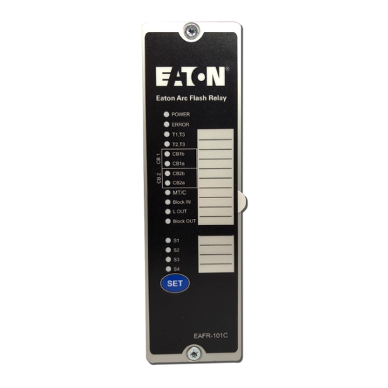
EAFR-101C arc point sensor relay
user manual
Effective November 2019
Contents
Description
1 Introduction . . . . . . . . . . . . . . . . . . . . . . . . . . . . 2
2 General . . . . . . . . . . . . . . . . . . . . . . . . . . . . . . . . 2
3 Operation and configuration . . . . . . . . . . . . . . . . 4
4 Arc sensors . . . . . . . . . . . . . . . . . . . . . . . . . . . . 7
5 System self-supervision . . . . . . . . . . . . . . . . . . . 8
6 Application examples . . . . . . . . . . . . . . . . . . . . . 9
7 Connections . . . . . . . . . . . . . . . . . . . . . . . . . . . . 9
8 Dimensions and installation . . . . . . . . . . . . . . . 11
9 Testing . . . . . . . . . . . . . . . . . . . . . . . . . . . . . . . 12
10 Troubleshooting guide . . . . . . . . . . . . . . . . . . . 14
11 Technical data . . . . . . . . . . . . . . . . . . . . . . . . . 14
12 Ordering codes . . . . . . . . . . . . . . . . . . . . . . . 16
Page
Advertisement
Table of Contents

Related Manuals for Eaton EAFR-101C


Summary of Contents for Eaton EAFR-101C
-
Page 1: Table Of Contents
Instruction Booklet IB0191002EN Effective November 2019 EAFR-101C arc point sensor relay user manual Contents Description Page 1 Introduction . . . . . . . . . . . . . . . . . . . . . . . . . . . . 2 2 General . -
Page 2: Introduction
– Circuit breaker can be applied for variety of applications . The EAFR-101C can be used as a stand-alone relay or as part of a more complex arc protec- CBFP –... - Page 3 Instruction Booklet IB0191002EN EAFR-101C arc point sensor relay user manual Effective November 2019 2.2 Simplified block diagram The EAFR-101C simplified block diagram (see Figure 2) shows the main components of the EAFR-101C relay . LATCH LATCH Power 24 Vdc 12 Vdc...
-
Page 4: Operation And Configuration
(see Section 3 .3 .1) situation, the corresponding LED for that sensor will start flashing and the ERROR LED will The EAFR-101C contains 16 indication LEDs . A user definable text activate . pocket can be slid in under the label for identifying each LED func- tion (except POWER and ERROR LEDs) . - Page 5 “Set” button for two tion selection . Dipswitch 3 is for configuring BI5 to operate as a seconds . The EAFR-101C sensor LEDs and all binary LEDs start Master Trip input or as a current information input . Dipswitch 4 and blinking .
- Page 6 Instruction Booklet IB0191002EN EAFR-101C arc point sensor relay user manual Effective November 2019 Table 2. EAFR-101 dipswitch setting selection. Dipswitch Function selection ON (left position) OFF (right position) Point sensor channels S1,S2 trip criteria. Trip on light only. (L) Trip on light and over-current. (L+C) Both signals are required simultaneously to trip.
-
Page 7: Arc Sensors
. The EAFR-101C only accepts light point sensors . sensor . No external mounting plates are needed . -
Page 8: System Self-Supervision
ERROR LED will turn off . If one or more of the sensors are disconnected, the healthy sensors remain in use and relay remains operational . The EAFR-101C will remain in error mode until the disconnected sensors are repaired . -
Page 9: Application Examples
Figure 6. EAFR-101C terminals at the rear plate. 7.1 Outputs 7.1.1 Trip relays T1, T2, and T3 The EAFR-101C relay has integrated trip relays T1 and T2 for tripping of the circuit-breakers . T1 and T2 relays are normally open type (NO) relays . - Page 10 50 ms . After 50 ms, if any light is still present, the EAFR-101C will then give a light out signal on BO1 . This blocking operation only occurs when a connected circuit breaker opens .
-
Page 11: Dimensions And Installation
Effective November 2019 8 Dimensions and installation The EAFR-101C is either door mounted or panel mounted in stan- dard, 19 in . (482 .6 mm) rack (height of 4U and 1/8 of a unit wide) . 175 (6.89) 160 (6.30) -
Page 12: Testing
LED indication . For arc light simulation, a suitable light source is provided as part of the Eaton AQS Tester kit . If an AQS Tester is not present, a camera flash can be used . A Canon Speedlite ®... - Page 13 Instruction Booklet IB0191002EN EAFR-101C arc point sensor relay user manual Effective November 2019 9.3 Test plan example Date: Substation: Switchgear: EAFR-101C serial number: Preconditions Light only Light + current Remarks Sensor channels 1 and 2 setting Sensor channels 3 and 4 setting...
-
Page 14: Troubleshooting Guide
Instruction Booklet IB0191002EN EAFR-101C arc point sensor relay user manual Effective November 2019 10 Troubleshooting guide 11 Technical data 11.1 Protection Table 5. Troubleshooting guide Problem Check Cross Reference Trip time using mechanical trip relays. 7 ms* Sensor does not activate... - Page 15 Instruction Booklet IB0191002EN EAFR-101C arc point sensor relay user manual Effective November 2019 11.7 Voltage tests Insulation test voltage Acc - to IEC 60255-5 2 kV, 50 Hz, 1 min Impulse test voltage Acc - to IEC 60255-5 5 kV, 1.2/50 us, 0.5 J 11.8 Mechanical tests...
-
Page 16: Ordering Codes
Instruction Booklet IB0191002EN EAFR-101C arc point sensor relay user manual Effective November 2019 12 Ordering codes Eaton catalog number Eaton style number Part number description EAFR-110P 65C2010G01 Current, point sensor unit EAFR-110F 65C2010G02 Current, fiber loop sensor unit EAFR-101 65C2010G03... - Page 17 Instruction Booklet IB0191002EN EAFR-101C arc point sensor relay user manual Effective November 2019 Notes: EATON www.eaton.com...
- Page 18 THIS DOCUMENT SHALL NOT BECOME PART OF OR MODIFY ANY CONTRACT BETWEEN THE PARTIES . In no event will Eaton be responsible to the purchaser or user in contract, in tort (including negligence), strict liability or other-wise for any special, indirect, incidental or consequential damage or loss...
Need help?
Do you have a question about the EAFR-101C and is the answer not in the manual?
Questions and answers