Suzuki Baleno Manuals
Manuals and User Guides for Suzuki Baleno. We have 2 Suzuki Baleno manuals available for free PDF download: Manual
Suzuki Baleno Manual (5653 pages)
SY413, SY416, SY418
Brand: Suzuki
|
Category: Automobile
|
Size: 298 MB
Table of Contents
-
Sdm8
-
Fuel System37
-
Fluid Change44
-
Engine Hood45
-
Seats46
-
Seat Belt46
-
Steering47
-
Heater Unit57
-
A / C Switch63
-
Compressor68
-
Evaporator69
-
Relay72
-
Wiring81
-
Condenser83
-
A/C Switch88
-
Drive Belt93
-
Tire Diagnosis107
-
Wear Indicators107
-
Radial Tire Lead109
-
Toe Setting110
-
Camber110
-
Toe Adjustment111
-
Steering Angle112
-
Lubrication115
-
Rack Plunger126
-
Steering Pinion126
-
Steering Rack126
-
Steering Wheel127
-
Special Tools128
-
Operation131
-
When Idling133
-
Relief Valve134
-
Steering Force137
-
Idle up System139
-
Fluid Leakage140
-
Tie Rod End Boot143
-
Cam Ring155
-
Rotor and Vane156
-
Reassembly157
-
Steering Column169
-
Front Suspension200
-
Rear Suspension224
-
Wheels and Tires261
-
Wheels262
-
Tire Placard265
-
Wheel Removal265
-
Tire Repair267
-
Balancing Wheels267
-
Steering Sensor272
-
Gravity Sensor273
-
Voltage Check286
-
Resistance Check288
-
On Floor297
-
On Lift297
-
Propeller Shafts318
-
Rear Drive Shaft322
-
Brakes326
-
Booster Assembly335
-
Bleeding Brakes350
-
Front Disc Brake362
-
Piston Seal365
-
Piston and Boot365
-
Inspect Springs378
-
Rear Disc Brake380
-
Fill Reservoir400
-
Brake Booster401
-
Rubber Parts405
-
Metal Parts405
-
Lspv410
-
System Schematic419
-
Driving Test425
-
Ebd Warning Lamp426
-
System Circuit430
-
G Sensor455
-
Oil Change463
-
Under Hood470
-
Fifth Gears472
-
Right Side487
-
Assembling Unit488
-
Output Shaft547
-
Steering Lock580
-
Road Test609
-
Manual Road Test610
-
“P” Range Test611
-
Changing Fluid616
-
Fluid Level617
-
Oil Cooler Hoses618
-
Oil Pan Gasket619
-
Oil Strainer620
-
Interlock Cable623
-
Stop Lamp Switch625
-
Select Cable627
-
Manual Selector630
-
Oil Pump645
-
Direct Clutch647
-
Forward Clutch650
-
Valve Body653
-
Dimension Data680
-
Select Lever753
-
O/D off Switch757
-
Solenoid Valves757
-
Unit Repair772
-
Unit Disassembly773
-
Reverse Clutch803
-
Differential824
-
Unit Assembly829
-
Clutch Cable848
-
Clutch Disc850
-
Clutch Cover850
-
Flywheel850
-
Clutch Pedal861
-
Clutch Fluid862
-
Brake Lights928
-
Circuit Breaker944
-
Back Door960
-
Front Door Lock1005
-
Front Door Assembly1007
-
Door Glass1008
-
Rear Door Lock1011
-
Rear Door Assembly1011
-
Front Fender1038
-
Front Bumper1039
-
Rear Bumper1040
-
Roof Rail1048
-
Front Seat1049
-
Rear Seat1050
-
Rear Seat Cushion1050
-
Seat Belts1052
-
Roof Lining1061
-
Sliding Roof1063
-
Key Coding1068
-
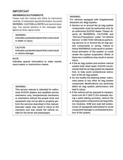
Air Bag System1101
-
Handling Precaution1164
-
Timing Chain Cover1567
-
Radiator Cap1636
-
Engine Fuel1656
-
Fuel Lines1658
-
Spark Plugs1918
-
Spark Plug1927
-
Related Manuals2009
-
BRAKE SYSTEM Brakes2010
-
Maintenance Schedule2015
-
Maintenance Service2018
-
Fuel System2023
-
Brake2071
-
Low Voltage2103
-
Oil Filter2141
-
Oil Cooler2142
-
Timing Belt2143
-
System Diagram2174
-
Vacuum Pump2180
-
Combination Meter2241
-
Warning Light2246
-
Wiring Diagram2272
-
Main Fuse Box2461
-
Power Supply Diagram2472
-
Main Fuse2472
-
Relay Box2472
-
Fusible Principal2474
-
Relaiskasten2477
-
Relaisbox2477
Advertisement
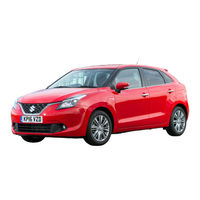
Suzuki Baleno Manual (468 pages)
Brand: Suzuki
|
Category: Automobile
|
Size: 36 MB
Table of Contents
-
-
Keys20
-
Door Locks21
-
Windows35
-
Mirrors39
-
Front Seats40
-
Rear Seats43
-
Fuel Gauge80
-
Speedometer80
-
Fuel Gauge90
-
Speedometer90
-
Tachometer90
-
Fuel Gauge103
-
Speedometer103
-
Tachometer103
-
Horn156
-
-
-
Ignition Switch162
-
Engine Switch164
-
Pedal171
-
Starting Engine172
-
Starting Engine173
-
Using Transaxle177
-
Braking241
-
Driving Tips
257-
Running-In258
-
Driving on Hills260
-
Highway Driving260
-
-
Fuel Filler Cap266
-
Engine Hood267
-
Sun Visor269
-
Interior Light270
-
Accessory Socket272
-
Assist Grips273
-
Glove Box273
-
Footrest276
-
Frame Hooks280
-
Heating System285
-
Radio Antenna300
-
-
-
Drive Belt380
-
Engine Coolant386
-
Air Cleaner388
-
Spark Plugs389
-
Gear Oil390
-
Clutch Pedal392
-
Brakes394
-
Steering397
-
Tires397
-
Battery400
-
Fuses403
-
Headlight Aiming406
-
Bulb Replacement407
-
Wiper Blades415
-
-
Towing431
-
Appearance Care435
-
Specifications445
-
Index451