Sign In
Upload
Manuals
Brands
KEB Manuals
Inverter
COMBIVERT F6
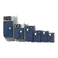
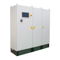
KEB COMBIVERT F6 Manuals
Manuals and User Guides for KEB COMBIVERT F6. We have
23
KEB COMBIVERT F6 manuals available for free PDF download: Programming Manual, Instructions For Use Manual, Instruction Manual
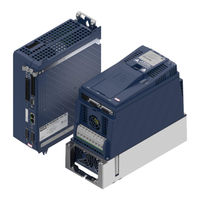
KEB COMBIVERT F6 Programming Manual (544 pages)
Brand:
KEB
| Category:
Servo Drives
| Size: 12.34 MB
Table of Contents
Preface
3
Signal Words and Symbols
3
More Symbols
3
Laws and Guidelines
4
Warranty
4
Support
4
Copyright
4
Table of Contents
5
Basic Safety Instructions
14
Target Group
14
Validity of this Manual
15
Electrical Connection
16
Start-Up and Operation
16
Product Description
17
Product Features
17
Functional Overview
17
Used Terms and Abbreviations
18
Table 3-1: Used Terms and Abbreviations
19
Motion Control
20
State Machine
20
Figure 1: State Machine
20
Changes of the State Machine
23
Control Word
24
Statusword
26
Display of the Actual State
27
Affect the Behaviour of the State Machine
28
Brake Control
30
Specification Brake Control F6-A / S6-A or F6-P S6-P
30
Specification Brake Control F6-K / S6-K
30
Functionality
31
Figure 2: Function Brake Control
31
Characteristics of the Brake Control
32
Influence of the Brake Control on the State Machine
35
Times of the Brake Control
35
Status of the Brake Control
35
Errors and Warnings
37
Errors
37
Figure 3: Process of a Fault Reaction
46
Figure 4: Example Co63
49
Automatic Reset of Errors
50
Warnings
51
Protection Functions
54
Overload (OL)
54
Figure 5: OL-Counter
54
Figure 6: Overload Characteristic
55
Overload Power Components (OL2)
56
Figure 7: Overload (OL2) Limiting Characteristic
57
Figure 8: Increase OL2 for 60A Rated Current and 40°C
59
Figure 9: Characteristic of the Current Limit in Relation to the Time
61
Overtemperature Heatsink (OH)
62
Figure 10: Overtemperature Heatsink (OH)
63
Overtemperature Unit (OHI)
64
Overtemperature Motor (Doh)
65
Figure 11: Sensor Calculation by Excel
67
Motor Protection Switch OH2
68
Figure 12: Tripping Motor Protection Switch
69
Figure 13: Dependence of the Motor Protection Function
70
Figure 14: Dependence of the Tripping Time
70
Figure 15: Determination of the Motor Protection Function Data from the Characteristics of the
71
Fieldbus Watchdog
72
Maximum Current
73
Effective Motor Load
74
Figure 16: Effective Motor Load
74
Maximum Acceleration or Deceleration
75
Monitor the Speed Difference
75
External Error / Warning Triggering
77
Safety Stop from Safety Module
77
Error Underpotential (up / Puready)
78
Overvoltage
82
Table 4-1: Overvoltage Level
82
Table 4-2: Permanent Damage Due to Overvoltage
82
Overspeed (ERROR Overspeed / ERROR Overspeed (EMF))
83
Encoder Monitoring
84
Limit Switch
85
Input Phases Failure Detection
88
Figure 17: Limit Switch
88
Motor Phase Failure Detection
89
UPS Mode (Not Available for Compact Cards)
92
Power off Function
92
Figure 18: Motor Operation
93
Figure 19: Regenerative Operation
94
Figure 20: Motor Operation Without Power-Off Function
94
Figure 21: Regenerative Operation in Case of Mains Power Failure
95
Figure 22: Control to Constant DC Link Voltage
95
Figure 23: Circuit Diagram of the DC Control (Ppz=Number of Pole Pairs)
100
Minimum Switch-Off Times
101
Blockade Handling
103
Monitoring of the Load
108
Quickstop
113
Minimum Current Monitoring in the Safety Module
113
Figure 24: Minimum Current Course
115
Braking Transistor
116
Braking Transistor Handling
116
Table 4-3: Switching Threshold for Braking Transistor
117
Braking Transistor Protective Functions
119
Power and Temperature Calculation at the Braking Resistor
120
Sub-Mounted Braking Resistor Protection
121
Fan Control
123
Fan Control F6
123
Fan Control S6-A / S6-K
124
Terminals Short Circuit Protection
124
Control Type K
124
Control Type a
124
Control Type P
125
Operating Modes
126
Operating Mode 1: Profile Position Mode
127
Figure 25: Profile Positioning Mode (1)
128
Figure 26: Profile Positioning Mode (2)
129
Figure 27: Single Positioning
129
Figure 28: Multi Positioning
130
Figure 29: Restart of a Positioning
130
Figure 30: Ramps in Profile Position Mode
136
Figure 31: Motor Encoder with Initiator at Rotary Table
140
Figure 32: Motor Encoder with Encoder and Initiator at Rotary Table
141
Figure 33: Operation with Motor Model and Encoder with Initiator at Rotary Table
141
Operating Mode 2: Velocity Mode
142
Figure 34: Velocity Mode - Overview
142
Figure 36: Target Speed Limitation
143
Figure 37: Ramp Generator
144
Figure 38: S-Curve Type = 0: Continuous S-Curve
148
Figure 39: S-Curve Type = 4: Abort in S-Curve
148
Figure 40: Pass Zero Type = 0: Not Zero
149
Figure 41: Pass Zero Type = 8: Zero
149
Figure 42: Calculation Example
150
Operating Mode 6: Homing Mode
151
Figure 43: Homing - Method 1
154
Figure 44: Homing - Method 2
155
Figure 45: Homing - Method 3 and 4
155
Figure 46: Homing - Method 5 and 6
156
Figure 47: Homing - Method 7 to 14 (23 to 26)
157
Figure 48: Homing - Method 33 and 34
158
Advertisement
KEB COMBIVERT F6 Instructions For Use Manual (104 pages)
HOUSING P
Brand:
KEB
| Category:
DC Drives
| Size: 8.63 MB
Table of Contents
Preface
3
Signal Words and Symbols
3
More Symbols
3
Laws and Guidelines
4
Warranty
4
Support
4
Copyright
4
Table of Contents
5
List of Figures
9
List of Tables
10
Glossary
11
Standards for Drive Converters / Control Cabinets
13
Product Standards that Apply Directly to the Drive Converter
13
Basic Standards to Which Drive Converter Standards Refer Directly
13
Standards that Are Used in the Environment of the Drive Converter
14
1 Basic Safety Instructions
15
Target Group
15
Transport, Storage and Proper Use
15
Installation
16
Electrical Connection
17
EMC-Compatible Installation
18
Voltage Test
18
Insulation Measurement
18
Start-Up and Operation
19
Maintenance
20
Repair
21
Disposal
21
2 Product Description
22
Specified Application
22
Residual Risks
22
Improper Use
22
Product Features
23
Part Code
24
Table 1: Part Code
24
3 Technical Data
25
Operating Conditions
25
Climatic Environmental Conditions
25
Table 2: Climatic Environmental Conditions
25
Mechanical Environmental Conditions
26
Chemical / Mechanical Active Substances
26
Table 3: Mechanical Environmental Conditions
26
Table 4: Chemical / Mechanical Active Substances
26
Electrical Operating Conditions
27
Device Classification
27
Electromagnetic Compatibility
27
Table 5: Device Classification
27
Table 6: Electromagnetic Compatibility
27
Block Diagram of Energy Flow in the Device
28
Figure 1: Block Diagram of Energy Flow in the Device
28
Technical Data 400V Class
29
Single Drive
29
Table 7: Technical Data of the 400V Class - Single Drive
30
Master / Slave System
31
Table 8: Technical Data of the 400 V Class Master / Slave
32
Master / Slave / Slave System
33
Table 9: Technical Data of the 400 V Class Master / Slave / Slave
34
Technical Data 690V Class
35
Single Drive
35
Table 10: Technical Data of the 690V Class - Single Drive
36
Master / Slave System
37
Table 11: Technical Data of the 690 V Class Master / Slave
38
Master / Slave / Slave System
39
Table 12: Technical Data of the 690 V Class Master / Slave / Slave
40
Dimensions and Weights
41
Dimensions Air Cooler Built-In Version
41
Figure 2: Dimensions Air Cooler Built-In Version
41
Dimensions Air-Cooled Inverter Through-Mount Version
42
Figure 3: Dimensions Air-Cooled Inverter Through-Mount Version
42
Dimensions Liquid Cooler Through-Mount Version
43
Figure 4: Dimensions Liquid Cooler Push-Through Version
43
Dimensions Liquid Cooler Installation Version
44
Figure 5: Dimensions Liquid Cooler Built-In Version
44
Dimensions Liquid Cooler Built-In Version with Stainless Steel Tube
45
Figure 6: Dimensions Liquid Cooler Built-In Version with Stainless Steel Tube
45
KEB COMBIVERT F6 Instructions For Use Manual (90 pages)
Brand:
KEB
| Category:
Controller
| Size: 8.98 MB
Table of Contents
Preface
3
Signal Words and Symbols
3
More Symbols
3
Laws and Guidelines
4
Warranty
4
Support
4
Copyright
4
Table of Contents
5
List of Figures
9
List of Tables
10
Glossar
11
Used Standards
13
1 Basic Safety Instructions
15
Target Group
15
Transport, Storage and Proper Use
15
Installation
16
Electrical Connection
17
EMC-Compatible Installation
18
Voltage Test
18
Insulation Measurement
18
Start-Up and Operation
19
Maintenance
20
Repair
20
Disposal
21
2 Product Description
23
Intended Use
23
Residual Risks
24
Improper Use
24
Type Code Cabinet System
25
Table 1: Type Code
25
3 Functional Overview
27
Figure 1: Functional Overview
27
Representation of the Electrical Power Unit with Higher-Level Control
28
Figure 2: Overview of the Electrical Power Unit
28
Representation of the Electrical Power Unit with Braking Option
29
Figure 3: Overview of the Electrical Power Unit with Braking Option
29
Structure of the Higher-Level Control
30
Figure 4: Structure of the Higher-Level Control
30
Structure of the Liquid Distribution
31
Figure 5: Structure of the Liquid Distribution
31
Structure of the Cabinet Air Conditioning
32
Figure 6: Structure of the Cabinet Air Conditioning
32
General Specifications
33
Machine Safety
33
Switching Frequency
34
Table 2: Switching Frequency
34
Emergency Stop Function
35
Figure 7: Emergency Stop Button
35
Overcurrent and Short-Circuit Protection
36
C6 HMI Program Functionalities
37
Self-Test at Power-On-Reset
37
Monitoring Cooling Circuit
37
Monitoring Mains
37
Data Logger
38
Visualisation
38
Advertisement
KEB COMBIVERT F6 Instructions For Use Manual (74 pages)
Brand:
KEB
| Category:
Media Converter
| Size: 7.61 MB
Table of Contents
Preface
3
Signal Words and Symbols
3
More Symbols
3
Laws and Guidelines
4
Warranty
4
Support
4
Copyright
4
Table of Contents
5
List of Figures
8
List of Tables
9
Glossary
10
Standards for Drive Converters / Control Cabinets
12
Product Standards that Apply Directly to the Drive Converter
12
Basic Standards to Which Drive Converter Standards Refer Directly
12
Standards that Are Used in the Environment of the Drive Converter
13
1 Basic Safety Instructions
14
Target Group
14
Transport, Storage and Proper Use
14
Installation
15
Electrical Connection
16
EMC-Compatible Installation
17
Voltage Test
17
Insulation Measurement
17
Start-Up and Operation
18
Maintenance
19
Repair
20
Disposal
20
2 Product Description
21
Specified Application
21
Residual Risks
21
Unintended Use
21
Product Features
22
Part Code
23
Table 1: Type Code
23
3 Technical Data
24
Operating Conditions
24
Climatic Environmental Conditions
24
Table 2: Climatic Environmental Conditions
24
Mechanical Ambient Conditions
25
Chemical / Mechanical Active Substances
25
Table 3: Mechanical Ambient Conditions
25
Table 4: Chemical / Mechanical Active Substances
25
Electrical Operating Conditions
26
Device Classification
26
Electromagnetic Compatibility
26
Table 5: Device Classification
26
Table 6: Electromagnetic Compatibility
26
Unit Data of the 400V Units
27
Overview
27
Table 7: Overview of the 400V Unit Data
27
Voltage and Frequencies
28
Example of the Calculation of the Possible Motor Voltage
28
Table 8: Input Voltages and Frequencies of the 400V Units
28
Table 9: DC Link Voltage for DC Operation of the 400V Units
28
Table 10: Output Voltages and Frequencies of the 400V Units
28
Input and Output Currents/ Overload
29
Table 11: Input Currents of the 400 V Units
29
Table 12: Output Currents 400 V Units
29
Overload Characteristic (OL)
30
Figure 1: Switch-Off Time T Depending on the Overload I/IN (OL)
30
Frequency-Dependent Maximum Current (OL2)
31
Figure 2: Typical Overload Characteristics in the Lower Output Frequencies (OL2) Example
32
Table 13: Frequency-Dependent Maximum Current for Unit Size 19
33
Table 14: Frequency-Dependent Maximum Current for Unit Size 20
33
Table 15: Frequency-Dependent Maximum Current for Unit Size 21
33
Table 16: Frequency-Dependent Maximum Current for Unit Size 22
33
Switching Frequency and Temperature
34
Table 17: Switching Frequency and Temperature of the 400 V Units
34
Power Dissipation at Nominal Operating
35
Protection of the Drive Converter
35
Table 18: Power Dissipation of the 400V Units
35
Table 19: Fusing of the 400 V / 480 V Units
35
DC Link / Braking Transistor Function GTR7
36
Table 20: DC Link / Braking Transistor Function of the 400 V Units
36
Figure 3: Block Diagram of the Energy Flow
37
Fan
38
Table 21: Fan
38
Switching Behaviour of the Fans
39
Switching Points of the Fans
39
Figure 4: Switching Behaviour of the Fans Example Heat Sink Fan
39
Table 22: Switching Points of the Fans
39
Dimensions and Weights
40
Built-In Version Air Cooler
40
Figure 5: Dimensions Mounted Version Air Cooler
40
Built-In Version Water Cooler
41
Figure 6: Dimensions Built-In Version Water Cooler
41
Through-Mount Version Air-Cooler IP20, IP54
42
Figure 7: Dimensions Through-Mount Version Air-Cooler IP20, IP54
42
Through-Mount Version Water-Cooler IP20, IP54
43
Figure 8: Dimensions Push-Through Version Water-Cooler IP20, IP54
43
Control Cabinet Installation
44
Figure 9: Mounting Distances
44
Figure 10: Control Cabinet Ventilation
44
KEB COMBIVERT F6 Instructions For Use Manual (80 pages)
Brand:
KEB
| Category:
Inverter
| Size: 9.44 MB
Table of Contents
Preface
3
Signal Words and Symbols
3
More Symbols
3
Laws and Guidelines
4
Warranty
4
Support
4
Copyright
4
Table of Contents
5
List of Figures
8
List of Tables
9
Glossar
10
Standards for Drive Converters / Control Cabinets
12
1 Basic Safety Instructions
14
Target Group
14
Transport, Storage and Proper Use
14
Installation
15
Electrical Connection
16
EMC-Compatible Installation
17
Voltage Test
17
Insulation Measurement
17
Start-Up and Operation
18
Maintenance
19
Repair
19
Disposal
20
2 Product Description
21
Product Features
21
Four Quadrant Operation
21
Specified Application
22
Residual Risks
22
Improper Use
22
Part Code
23
Table 1: Part Code
23
3 Functional Overview
24
Schematic Diagram of the Electrical Power Unit for the Q4 Operation
24
Figure 1: Schematic Diagram of the Electrical Power Unit
24
Interior Ventilation
25
Figure 2: Interior Ventilation
25
4 Mechanical Installation
26
Cooling System
26
Connection Cooling System
26
Coolant Connections of the Drive Converter
27
Figure 3: Coolant Connections of the Drive Converter
27
Wiring Diagram Cooling System
28
Figure 4: Wiring Diagram Cooling System
28
Dimensions of the Housing
29
Figure 5: Dimensions of the Housing
29
Fixing Points at the Housing
30
Figure 6: Fixing Points at the Housing
30
Assembly Aids
31
Figure 7: Lifting Device
31
Figure 8: Eyebolts
32
Figure 9: Assembly Aids
32
Assembly in the Control Cabinet
33
Assembly of the Slide Rails and Safety Devices at the Drive Converter
33
Figure 10: Assembly of the Slide Rails
33
Function of the Locking Levers
34
Figure 11: Function of the Locking Levers
34
Assembly of the Side Guide Rails
35
Figure 12: Assembly of the Side Guide Rails
35
Positions of the Side Guide Rails in the Control Cabinet
36
Figure 13: Positions of the Side Guide Rails in the Control Cabinet
36
Figure 14: Distances
37
Installation of the Drive Converter in the Control Cabinet
38
Figure 15: Schematic Diagram
38
Figure 16: Transport
39
Figure 17: Connect the Drive Converter Housing V with the Control Cabinet
40
Figure 18: Fix the Drive Converter Housing V in the Control Cabinet
41
Figure 19: Drive Converter Housing V Assembled in the Control Cabinet
42
Disassembly from the Control Cabinet
43
KEB COMBIVERT F6 Instructions For Use Manual (74 pages)
INSTALLATION F6 HOUSING 6
Brand:
KEB
| Category:
Servo Drives
| Size: 4.64 MB
Table of Contents
Preface
3
Signal Words and Symbols
3
More Symbols
3
Laws and Guidelines
4
Warranty
4
Support
4
Copyright
4
Table of Contents
5
List of Figures
8
List of Tables
9
Glossary
10
Standards for Drive Converters / Control Cabinets
12
Product Standards that Apply Directly to the Drive Converter
12
Basic Standards to Which Drive Converter Standards Refer Directly
12
Standards that Are Used in the Environment of the Drive Converter
13
1 Basic Safety Instructions
14
Target Group
14
Transport, Storage and Proper Use
14
Installation
15
Electrical Connection
16
EMC-Compatible Installation
17
Voltage Test
17
Insulation Measurement
17
Start-Up and Operation
18
Maintenance
19
Repair
19
Disposal
20
2 Product Description
22
Specified Application
22
Residual Risks
22
Unintended Use
22
Product Features
23
Part Code
24
Table 1: Part Code
24
3 Technical Data
25
Operating Conditions
25
Climatic Ambient Conditions
25
Table 2: Climatic Ambient Conditions
25
Mechanical Ambient Conditions
26
Chemical / Mechanical Active Substances
26
Table 3: Mechanical Ambient Conditions
26
Table 4: Chemical / Mechanical Active Substances
26
Electrical Operating Conditions
27
Overvoltage
27
Electromagnetic Compatibility
27
Table 5: Overvoltage
27
Table 6: Electromagnetic Compatibility
27
Unit Data of the 400V Units
28
Overview
28
Table 7: Overview of the 400V Unit Data
28
Voltage and Frequencies
29
Table 8: Input Voltages and Frequencies of the 400V Units
29
Table 9: Input Voltages for DC Operation of the 400V Units
29
Table 10: Output Voltages and Frequencies of the 400V Units
29
Input and Output Currents/ Overload
30
Table 11: Input Currents of the 400V Units
30
Table 12: Output Currents
30
Overload Characteristic (OL)
31
Figure 1: Switch-Off Time T Depending on the Overload I/IN (OL)
31
Frequency-Dependent Maximum Current (OL2)
32
Figure 2: Overload Characteristic in the Lower Speed Range (OL2) Example Unit Size 23
33
Table 13: Frequency-Dependent Maximum Current for Unit Size 21
33
Table 14: Frequency-Dependent Maximum Current for Unit Size 22
33
Switching Frequency and Temperature
34
Table 15: Frequency-Dependent Maximum Current for Unit Size 23
34
Table 16: Frequency-Dependent Maximum Current for Unit Size 24
34
Table 17: Switching Frequency and Temperature of the 400 V Units
34
Power Dissipation at Nominal Operating
35
Protection of the Drive Converter
35
Table 18: Power Dissipation of the 400V Units
35
Table 19: Fusing of the 400 V / 480 V Units
35
DC Link / Braking Transistor Function GTR7
36
Figure 3: Block Diagram of the Energy Flow
36
Table 20: DC Link / Braking Transistor Function of the 400 V Units
36
Fan
37
Dimensions and Weights
38
Mounted Version Air Cooler
38
Figure 4: Dimensions Mounted Version Air Cooler
38
Mounted Version Water Cooler
39
Figure 5: Dimensions Mounted Version Water Cooler
39
Through-Mount Version Air Cooler IP54
40
Figure 6: Dimensions Through-Mount Version Air Cooler IP54
40
Through-Mount Version Water Cooler IP54
41
Figure 7: Dimensions Through-Mount Version Water Cooler IP54
41
Control Cabinet Installation
42
Figure 8: Mounting Distances
42
Figure 9: Control Cabinet Ventilation
42
KEB COMBIVERT F6 Instructions For Use Manual (54 pages)
Brand:
KEB
| Category:
Controller
| Size: 6.39 MB
Table of Contents
Table of Contents
3
1 Introduction
8
Markings
8
Warnings
8
Information Notes
8
Symbols and Markers
9
Laws and Guidelines
9
Warranty and Liability
9
Support
9
Copyright
10
Validity of this Manual
10
Target Group
10
2 General Safety Instructions | 2
11
Installation
11
Start-Up and Operation
12
Maintenance
12
3 Product Description | 3
13
Description of the Control Board COMPACT
13
Variants of the Control Board
13
Safety Functions
13
Accessories
14
Connection and Control Elements
14
Tab. 1 Connector Sets
14
Tab. 2 Overview Connection and Operating Elements
14
Motor Monitoring X1C (Temperature, Brake)
15
Control Terminal Strip X2A
15
Safety Terminal Block X2B
15
CAN Bus and Analog Inputs and Outputs X2C
15
Encoder Interfaces X3A, X3B
15
Diagnostic Interface X4A
15
Fieldbus Interfaces X4B, X4C
15
Status Leds
16
Boot Display
16
VCC - Led
16
Net St - Led
16
Dev St - Led
16
Tab. 3 Leds at Power on
16
Tab. 4 Function VCC LED
16
Tab. 5 Function NET ST - LED
16
Opt - Led
17
Tab. 6 Function DEV ST - LED
17
Tab. 7 Function OPT - LED
17
4 Connection of the Control
18
Assembly of Wires
18
Tab. 8 Wire End Ferrules and Stripping Length
18
Terminal Strip X2A
19
Tab. 9 Assignment of the Terminal Strip X2A
19
Digital Inputs
20
Digital Outputs
20
Relay Output
21
Voltage Supply
21
Terminal Block X2B
22
Inputs STO
22
Digital Outputs
22
Tab. 10 Assignment of the Terminal Strip X2B
22
Tab. 11 OSSD Pulse Width Depending on the Input Voltage
22
Voltage Input
23
Tab. 12 Calculation the Current Consumption
23
Terminal Block X2C
24
Analog Input
24
Tab. 13 Assignment of the Terminal Block X2C
24
Analog Output
25
KEB COMBIVERT F6 Instructions For Use Manual (56 pages)
Brand:
KEB
| Category:
DC Drives
| Size: 6.69 MB
Table of Contents
Table of Contents
3
Introduction
7
Used Markers
7
Warnings
7
Information Notes
8
Symbols and Markers
8
Laws and Guidelines
8
Warranty and Liability
8
Support
8
Copyright
9
Validity of this Manual
9
Target Group
9
General Safety Instructions
10
Installation
10
Start-Up and Operation
11
Maintenance
11
Product Description
12
Description of the Control Board COMPACT
12
Variants of the Control Board Pro
12
Safety Functions
12
Accessories
13
Table 1 Connector Sets
13
Connection and Control Elements
14
Motor Monitoring X1C (Temperature, Brake)
14
Control Terminal Strip X2A
14
Table 2 Overview Connection and Control Elements
14
Safety Terminal Block X2B
15
CAN Bus and Analog Inputs and Outputs X2C
15
Encoder Interfaces X3A, X3B
15
Diagnostic Interface X4A
15
Fieldbus Interfaces X4B, X4C
15
Status Leds
15
Boot Display
15
VCC - Led
16
Net St - Led
16
Dev St - Led
16
Opt - Led
16
Table 3 Leds at Power on
16
Table 4 Function VCC LED
16
Table 5 Function NET ST - LED
16
Table 6 Function DEV ST - LED
16
Table 7 Function OPT - LED
16
Connection of the Control
17
Assembly of Wires
17
Table 8 Wire-End Ferrules and Stripping Length
17
Terminal Strip X2A
18
Digital Inputs
18
Table 9 Assignment of the Terminal Strip X2A
18
Digital Outputs
19
Relay Output
19
KEB COMBIVERT F6 Instructions For Use Manual (46 pages)
Brand:
KEB
| Category:
Controller
| Size: 3.02 MB
Table of Contents
Preface
3
Signal Words and Symbols
3
More Symbols
3
Laws and Guidelines
4
Warranty and Liability
4
Support
4
Copyright
4
Table of Contents
5
List of Figures
7
List of Tables
8
Glossary
9
Standards for Controls with / Without Safety Technology
11
1 Basic Safety Instructions
13
Target Group
13
Validity of this Manual
13
Electrical Connection
14
Start-Up and Operation
14
2 Control
15
Description of the Control
15
Type Code F6 with Control Unit Pro
15
Accessories
15
Table 1: Accessories
15
Overview of the Connection and Control Elements
16
Figure 1: Overview Control
16
Control Terminal Block (X2A)
17
Diagnostic Interface (X4A)
17
Encoder Interfaces (X3A, X3B)
17
Fieldbus Interface (X4B)
17
Fieldbus Interface (X4C)
17
Motor Monitoring X1C (Temperature, Brake)
17
Safety Terminal Block (X2B)
17
Boot Display
18
Net St - Led
18
Rotary Coding Switches (S1, S2) - in Preparation
18
Status Leds
18
Table 2: Leds at Power on
18
Table 3: LED Function VCC
18
Table 4: LED Function NET-ST
18
VCC - Led
18
Dev St - Led
19
Opt - Led
19
Connection of the Control
19
Table 5: LED Function DEV-ST
19
Table 6: LED Function OPT
19
Assembly of the Wires to PUSH in Terminals
20
Figure 2: Assembly of the Control Cable
20
Table 7: Wire-End Ferrules and Stripping Length
20
Assignment of the Terminal Strip X2A
21
Figure 3: Assignment of the Terminal Strip X2A
21
Connection And Specification Of The Digital Inputs
22
Figure 4: Connection of the Digital Inputs at X2A
22
Table 8: Voltage Output of the Control
22
Table 9: Specifications of the Digital Inputs
22
Voltage Output of the Control Terminal Block
22
Connection And Specification Of The Digital Outputs
23
Connection And Specification Of The Relay Output
23
Figure 5: Examples for the Connection of the Digital Outputs at X2A
23
Table 10: Specifications of the Digital Outputs
23
Table 11: Specifications of the Relay Output
23
Figure 6: Connection of the Relay Output
24
Specification And Connection Of The Analog Inputs
24
Table 12: Specification of the Analog Inputs AN1 and AN2
24
Figure 7: Examples for the Connection of the Digital Outputs at X2A
25
Table 13: Specification of the Analog Input 3
25
Figure 8: Example for the Connection of the Analog Output to X2A
26
Specification And Connection Of The Analog Output
26
Table 14: Specifications of the Analog Output
26
Figure 9: Voltage Output of the Control
27
Table 15: Calculation the Current Consumption
27
Voltage Input P24Vin (X2A.28)
27
Voltage Output 24Voutctrl (X2A.26)
27
Voltage Supply
27
Figure 10: Voltage Input with External Power Supply
28
Figure 11: Voltage Input with External Power Supply
28
Mixed Voltage Supply
28
Figure 12: Mixed Voltage Supply of the Control
29
Terminal Block X2B
30
Table 16: Material Number of the Safety Module
30
Diagnosis/Visualisation
31
Assignment of the Interface X4A
31
Figure 13: PIN Assignment of the Serial Interface X4A
31
Table 17: Serial Interfaces
31
Table 18: Connecting Cable
31
Data Cable RS232 PC to Inverter
32
USB-Serial Converter
32
Connection of the RS485 Interface
32
Figure 14: Serial Cable for the Connection to a PC
32
Fieldbus Interfaces
33
Ethercat
33
Ehtercat in (X4B) and Ethercat out (X4C)
33
Blink Code NET ST - LED
33
Figure 15: Ethercat in / out and Blink Code of the Leds
33
Table 19: PIN Description RJ45 Ethercat
33
Figure 16: Blink Code „NET ST" - LED in Mode Ethercat
34
Encoder Interfaces
35
Multi-Encoder-Interface
35
Assignment of the Encoder Interfaces X3A and X3B
35
Table 20: Supported Encoders on Channel a
35
Table 21: Supported Encoders on Channel B
35
Input Signals
36
Figure 17: Assignment of the Input Signals (as Difference Signals)
36
Table 22: Assignment of X3A/X3B Depending on the Adjusted Encoder Interface
37
Description of the Encoder Interfaces
38
Table 23: Encoder Specifications
39
Brake Control and Temperature Detection
40
Specification And Connection Of The Brake / Relay Control
40
Figure 18: Assignment of the Terminal Block X1C
40
Table 24: Specification of the Brake Control
40
Specification And Connection Of The Temperature Detection
41
Operation Without Temperature Detection
41
Table 25: Specification of the Temperature Input
41
Connection of a KTY Sensor
42
Connection of PTC, Temperature Switch or PT1000
42
Figure 19: Connection of a KTY Sensor
42
Table 26: Connection of a KTY Sensor
42
Table 27: Connection of PTC, Temperature Switch or PT1000
42
Figure 20: Connection Examples of Different Temperature Sensors
43
KEB COMBIVERT F6 Instruction Manual (50 pages)
Brand:
KEB
| Category:
Portable Generator
| Size: 4.92 MB
Table of Contents
Table of Contents
3
Preface
6
Information on Special Measures
6
Documentation
6
Validity and Liability
7
Copyright
7
Specified Application
8
Product Description
8
Unit Identification
9
Table 1: Unit Identification
9
Installation Instructions
10
Cooling Systems
10
Control Cabinet Installation
11
Figure 1: Control Cabinet Installation
11
Safety and Application Notes
12
Technical Data
13
Operating Conditions
13
Table 2: Operating Conditions
13
Technical Data of the 400 V Class
14
Table 3: Technical Data of the 400 V Class
14
Dimensions and Weights
15
Heat Sink with Cooling Fan (Wall Mounted Version)
15
Figure 2: Heat Sink with Cooling Fan (Wall Mounted Version)
15
Heat Sink with Cooling Fan (Through-Mount Version)
16
Figure 3: Heat Sink with Cooling Fan (Through-Mount Version)
16
Water-Cooled Inverter - Wall Mounted Version
17
Figure 4: Water-Cooled Inverter - Wall Mounted Version
17
Water-Cooled Heat Sink (Second Version)- Mounted Version
18
Figure 5: Water-Cooled Heat Sink (Second Version)- Mounted Version
18
Water-Cooled Inverter - Through-Mount Version
19
Figure 6: Water-Cooled Inverter - Through-Mount Version
19
Terminal Strips of the Power Circuit
20
Mains Input
20
Figure 7: View Mains Input
20
Figure 8: Mains Input 3-Phase (B6-Rectifier)
21
Figure 9: Mains Input 3-Phase (B6-Rectifier)
21
Figure 10: Mains Input DC Without Precharging
21
Figure 11: Protective Earth Conductor Connection
21
Motor Output
22
Figure 12: View Motor Output Side
22
Figure 13: Motor Terminal Strip X1B
22
Other Terminals
23
Figure 14: Terminal Strip for DC Link and Braking Resistor X1C
23
Figure 15: Terminal Strip for Temperature Detection and Braking Transistor Monitoring X1D
23
Figure 16: Connection for Shielding and Protective Earth Conductor X1E
24
Figure 17: Terminal Strip for External Fan Power Supply X1F
24
Accessories
25
Filter and Chokes
25
Table 4: Connection Accessories
25
Connection Power Unit
26
KEB COMBIVERT F6 Instructions For Use Manual (50 pages)
Brand:
KEB
| Category:
Controller
| Size: 5.24 MB
Table of Contents
Table of Contents
3
Introduction | 1
7
Markings
7
Warnings
7
Information Notes
7
Symbols and Markers
8
Laws and Guidelines
8
Warranty and Liability
8
Support
8
Copyright
8
Validity of this Manual
9
General Safety Instructions
10
Installation
10
Start-Up and Operation
11
Maintenance
11
Product Description
12
Description of the Control Board PRO
12
Variants of the Control Board
12
Accessories
13
Connection and Control Elements
13
Motor Monitoring X1C (Temperature, Brake)
13
Tab. 1 Connector Sets
13
Tab. 2 Overview Connection- and Control Elements
13
Control Terminal Strip X2A
14
Safety Terminal Block X2B
14
Encoder Interfaces X3A, X3B
14
Diagnostic Interface X4A
14
Fieldbus Interface X4B
14
Fieldbus Interface X4C
14
Rotary Coding Switch
14
Status Leds
15
Boot Display
15
VCC - Led
15
Net St - Led
15
Dev St - Led
15
Opt - Led
15
Tab. 3 Leds at Power on
15
Tab. 4 Function VCC LED
15
Tab. 5 Function NET ST - LED
15
Tab. 6 Function DEV ST - LED
15
Connection of the Control | 4
17
Assembly of Wires
17
Tab. 8 Wire End Ferrules and Stripping Length
17
Terminal Strip X2A
18
Tab. 9 Assignment of the Terminal Strip X2A
18
Digital Inputs
19
Digital Outputs
20
Relay Output
20
Analog Input
22
Analog Output
23
KEB COMBIVERT F6 Instructions For Use Manual (52 pages)
Brand:
KEB
| Category:
DC Drives
| Size: 5.51 MB
Table of Contents
Table of Contents
3
Introduction
7
Used Markers
7
Warnings
7
Information Notes
8
Symbols and Markers
8
Laws and Guidelines
8
Warranty and Liability
8
Support
8
Copyright
9
Validity of this Manual
9
Target Group
9
General Safety Instructions
10
Installation
10
Start-Up and Operation
11
Maintenance
11
Product Description
12
Description of the Control Board PRO
12
Variants of the Control Board Pro
12
Accessories
12
Connection and Control Elements
13
Motor Monitoring X1C (Temperature, Brake)
13
Control Terminal Strip X2A
13
Table 1 Connector Sets
13
Table 2 Overview Connection and Control Elements
13
Safety Terminal Block X2B
14
Encoder Interfaces X3A, X3B
14
Diagnostic Interface X4A
14
Fieldbus Interface X4B
14
Fieldbus Interface X4C
14
Rotary Coding Switch S1, S2
14
Status Leds
14
Boot Display
14
VCC - Led
15
Net St - Led
15
Dev St - Led
15
Opt - Led
15
Table 3 Leds at Power on
15
Table 4 Function VCC LED
15
Table 5 Function NET ST - LED
15
Table 6 Function DEV ST - LED
15
Table 7 Function OPT - LED
15
Connection of the Control
16
Assembly of Wires
16
Table 8 Wire-End Ferrules and Stripping Length
16
Terminal Strip X2A
17
Table 9 Assignment of the Terminal Strip X2A
17
Digital Inputs
18
Digital Outputs
18
Relay Output
19
KEB COMBIVERT F6 Instructions For Use Manual (42 pages)
Application Drive; INSTALLATION F6 A-CONTROL
Brand:
KEB
| Category:
Control Unit
| Size: 2.17 MB
Table of Contents
Preface
3
Signal Words and Symbols
3
More Symbols
3
Laws and Guidelines
4
Warranty
4
Support
4
Copyright
4
Table of Contents
5
List of Figures
7
List of Tables
8
Glossary
9
Standards for Controls with / Without Safety Technology
11
1 Basic Safety Instructions
13
Target Group
13
Validity of this Manual
13
Electrical Connection
14
Start-Up and Operation
14
2 Control
15
Description of the Control
15
Connection Accessories
15
Overview of the Connection and Control Elements
16
Figure 1: Overview Control Board
16
Control Terminal Block (X2A)
17
Diagnostic Interface (X4A)
17
Encoder Interfaces (X3A, X3B)
17
Real-Time Ethernet Module (RTE)
17
Safety Terminal Block (X2B)
17
Temperature Monitoring and Brake Control (X1C)
17
Boot Display
18
Net St - Led
18
Status Leds
18
Table 1: Leds at Power on
18
Table 2: LED Function VCC
18
Table 3: LED Function FB-ST
18
VCC - Led
18
Dev St - Led
19
Opt - Led
19
Connection of the Control
19
Table 4: LED Function DEV-ST
19
Table 5: LED Function OPT
19
Assembly of the Wires to PUSH in Terminals
20
Figure 2: Assembly of the Control Cable
20
Table 6: Wire-End Ferrules and Stripping Length
20
Assignment of the Terminal Strip X2A
21
Figure 3: Assignment of the Terminal Strip X2A
21
Connection And Specification Of The Digital Inputs
22
Figure 4: Connection of the Digital Inputs at X2A
22
Table 7: Voltage Output of the Control
22
Table 8: Specifications of the Digital Inputs
22
Voltage Outputs of the Control Terminal Block
22
Connection And Specification Of The Digital Outputs
23
Connection And Specification Of The Relay Output
23
Figure 5: Examples for the Connection of the Digital Outputs at X2A
23
Table 10: Specifications of the Relay Output
23
Table 9: Specifications of the Digital Outputs
23
Figure 6: Example for the Connection of the Relay Output to X2A
24
Figure 7: Examples for the Connection of the Digital Outputs at X2A
24
Specification And Connection Of The Analog Inputs
24
Table 11: Specifications of the Analog Inputs
24
Figure 8: Example for the Connection of the Analog Output to X2A
25
Figure 9: Voltage Input of the Control
25
Specification And Connection Of The Analog Output
25
Table 12: Specification of the Analog Input 3
25
Table 13: Specifications of the Analog Output
25
Voltage Input for Supply of the Control Board and the Brake
25
Terminal Block X2B
26
Table 14: Material Number of the Safety Module
26
Diagnosis/Visualisation
27
Assignment of the Interface X4A
27
Figure 10: PIN Assignment of the Serial Interface X4A
27
Table 15: Serial Interfaces
27
Table 16: Connecting Cable
27
Data Cable RS232 PC Inverter
28
USB-Serial Converter
28
Connection of the RS485 Interface
28
Figure 11: Serial Cable for the Connection to a PC
28
Fieldbus Interfaces
29
Can
29
Connection And Specification Of The Can Bus
29
Figure 12: Connection CAN Bus to Terminal Block X2A
29
Table 17: Specifications of the CAN Bus
29
Blink Code NET ST - LED in CAN Mode
30
Figure 13: Blink Code „NET ST" - LED in Mode CAN
30
Encoder Interfaces
31
Assignment of the Encoder Interfaces X3A and X3B
31
Table 18: Supported Encoders on Channel a
31
Table 19: Supported Encoders on Channel B
31
Input Signals
32
Figure 14: Assignment of the Input Signals (as Difference Signals)
32
Table 20: Assignment of X3A/X3B Depending on the Adjusted Encoder Interface
33
Brake Control and Temperature Detection
36
Specification And Connection Of The Brake Control
36
Specification And Connection Of The Temperature Detection
36
Figure 15: Assignment of the Terminal Block X1C
36
Figure 16: Example for the Connection of the Brake Output at X1C
36
Table 22: Specification of the Brake Control
36
Table 23: Specification of the Temperature Input
37
Operation Without Temperature Detection
38
Connection of a KTY Sensor
38
Connection of PTC, Temperature Switch or PT1000
38
Figure 17: Connection of a KTY Sensor
38
Table 24: Connection of a KTY Sensor
38
Table 25: Connection of PTC, Temperature Switch or PT1000
38
Figure 18: Connection Examples of Different Temperature Sensors
39
KEB COMBIVERT F6 Instructions For Use Manual (48 pages)
Brand:
KEB
| Category:
Industrial Electrical
| Size: 5.46 MB
Table of Contents
Table of Contents
3
Introduction | 1
7
Markings
7
Warnings
7
Information Notes
7
Symbols and Markers
8
Laws and Guidelines
8
Warranty and Liability
8
Support
8
Copyright
8
Validity of this Manual
9
General Safety Instructions
10
Installation
10
Start-Up and Operation
11
Maintenance
11
Product Description
12
Description of the Control Board PRO
12
Variants of the Control Board Pro
12
Accessories
12
Connection and Control Elements
13
Motor Monitoring X1C (Temperature, Brake)
13
Control Terminal Strip X2A
13
Tab. 1 Connector Sets
13
Tab. 2 Overview Connection and Control Elements
13
Safety Terminal Block X2B
14
Encoder Interfaces X3A, X3B
14
Diagnostic Interface X4A
14
Fieldbus Interface X4B
14
Fieldbus Interface X4C
14
Rotary Coding Switch
14
Status Leds
14
Boot Display
14
VCC - Led
15
Net St - Led
15
Dev St - Led
15
Opt - Led
15
Tab. 3 Leds at Power on
15
Tab. 4 Function VCC LED
15
Tab. 5 Function NET ST - LED
15
Tab. 6 Function DEV ST - LED
15
Tab. 7 Function OPT - LED
15
Connection of the Control
16
Assembly of Wires
16
Tab. 8 Wire-End Ferrules and Stripping Length
16
Terminal Strip X2A
17
Digital Inputs
17
Tab. 9 Assignment of the Terminal Strip X2A
17
Digital Outputs
18
Relay Output
19
Analog Input
20
KEB COMBIVERT F6 Instructions For Use Manual (42 pages)
Brand:
KEB
| Category:
Controller
| Size: 5.5 MB
Table of Contents
Table of Contents
3
Introduction | 1
7
Markings
7
Warnings
7
Information Notes
7
Symbols and Markers
8
Laws and Guidelines
8
Warranty and Liability
8
Support
8
Copyright
9
Validity of this Manual
9
Target Group
9
General Safety Instructions
10
Installation
10
Start-Up and Operation
11
Maintenance
11
Product Description
12
Description of the Control Board APPLIKATION
12
Variants of the Control Board
12
Accessories
12
Connection and Control Elements
13
Motor Monitoring X1C (Temperature, Brake)
13
Tab. 1 Connector Sets
13
Tab. 2 Overview Connection and Operating Elements
13
Control Terminal Strip X2A
14
Safety Terminal Block X2B
14
Encoder Interfaces X3A, X3B
14
Diagnostic Interface X4A
14
Realtime-Ethernet Module
14
Status Leds
14
Boot Display
14
VCC - Led
15
Net St - Led
15
Dev St - Led
15
Opt - Led
15
Tab. 3 Leds at Power on
15
Tab. 4 Function VCC LED
15
Tab. 5 Function NET ST - LED
15
Tab. 6 Function DEV ST - LED
15
Tab. 7 Function OPT - LED
15
Connection of the Control
16
Assembly of Wires
16
Tab. 8 Wire End Ferrules and Stripping Length
16
Terminal Strip X2A
17
Tab. 9 Assignment of the Terminal Strip X2A
17
Digital Inputs
18
Digital Outputs
18
Relay Output
19
Analog Input
20
Analog Output
21
KEB COMBIVERT F6 Instructions For Use Manual (40 pages)
Functional safety
Brand:
KEB
| Category:
Controller
| Size: 1.6 MB
Table of Contents
Preface
3
Signal Words and Symbols
3
More Symbols
3
Laws and Guidelines
4
Warranty and Liability
4
Support
4
Copyright
4
Table of Contents
5
List of Figures
7
List of Tables
8
Glossary
9
Standards for Drive Converters / Control Cabinets
11
Product Standards that Apply Directly to the Drive Converter
11
Basic Standards to Which Drive Converter Standards Refer Directly
11
Standards that Are Used in the Environment of the Drive Converter
12
1 Basic Safety Instructions
13
Target Group
13
Validity of this Manual
13
Electrical Connection
14
Start-Up and Operation
14
2 Product Description
15
Device Identification
15
Table 1: Numerical Code
15
3 Safety Functions
16
General Instructions
16
Safe Torque off (Safe Torque off - STO)
17
Emergency Stop According en 60204
18
Calculation of the Rotation Angle Triggered by the Jerk
18
Table 2: Calculation of the Jerk
18
Classification Of Sto According Iec 61508
19
Classification Of Sto According En Iso 13849
19
Safe Brake Control (Safe Brake Control - SBC)
19
Requirements for the Brake
19
Table 3: Classifications of STO
19
Table 4: Requirements for the Brake
19
Classification Of Sbc According Iec 61508
20
Classification Of Sbc According En Iso 13849
20
Table 5: Classifications of SBC
20
4 Description of the Terminals
21
Figure 1: Description of the Terminals
21
Table 6: Mechanical Specification of Terminal Strip X2B
21
Inputs
22
Specification Of The Sto Inputs
22
STO with OSSD Signals
22
Specification Of The Sbc Inputs
22
SBC with OSSD Signals
22
Table 7: Specification of the STO Inputs
22
Table 8: STO with OSSD Signals
22
Table 9: Specification of the SBC Inputs
22
Outputs
23
Output STO
23
Output SBC
23
Brake Output
23
Status Leds
23
Status-LED Safety Module
23
Table 10: Status-LED Safety Module
23
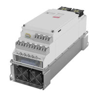
KEB COMBIVERT F6 Instruction Manual (48 pages)
Housing U 55...90kW 230V 75...200kW 400V
Brand:
KEB
| Category:
DC Drives
| Size: 4.68 MB
Table of Contents
Table of Contents
3
1 Preface
5
General
5
Validity and Liability
5
Copyright
6
Specified Application
6
Product Description
6
Part Code
7
Transport Instructions
8
Installation Instructions
8
Cooling Systems
8
Control Cabinet Installation
9
Assembly Aid
9
Safety and Application Notes
10
2 Technical Data
11
Operating Conditions
11
Technical Data of the 230V Class
12
Technical Data of the 400 V Class
13
DC Supply
14
Calculation of the DC Input Current
14
Internal Input Circuit
14
Dimensions and Weights
15
Mounted Version with Sub Construction (Default)
15
Through-Mount Version Heat Sink with Fan (Size 24
16
Mounted Version Water-Cooled Heat Sink
17
Through-Mount Version Water-Cooled Heat Sink
18
Through-Mount Version Water-Cooled Heat Sink with Stud
19
Through-Mount Version Water-Cooled Heat Sink with Stud (Small Design)
20
Through-Mount Version Water-Cooled Heat Sink Without Stud (Small Design)
21
Terminal Strips of the Power Circuit
22
Terminal Strips for 400V Units
22
Terminal Strips for 230V Units
26
Connection Accessories
28
Filter and Chokes
28
Connection Power Unit
29
Mains and Motor Connection
29
Selection of the Motor Cable
30
Connection of the Motor
30
Temperature Detection T1, T2
31
2.7.4.1 Use of the Temperature Input in KTY Mode
32
2.7.4.2 Use of the Temperature Input in PTC Mode
32
Connection of a Braking Resistor
33
2.7.5.1 Braking Resistor Without Temperature Monitoring
34
2.7.5.2 Braking Resistor with Over-Heat Protection and GTR7 Monitoring
34
2.7.5.3 Braking Resistor with Over-Heat Protection Without GTR7 Monitoring
35
External Fan Power Supply
36
Annex a
37
Overload Characteristic
37
Overload Protection in the Lower Speed Range
37
A.1 Overload Characteristic
37
KEB COMBIVERT F6 Instructions For Use Manual (38 pages)
Brand:
KEB
| Category:
Controller
| Size: 7.57 MB
Table of Contents
Preface
3
Signal Words and Symbols
3
More Symbols
3
Laws and Guidelines
4
Warranty and Liability
4
Support
4
Copyright
4
Table of Contents
5
List of Figures
7
List of Tables
7
1 Basic Safety Instructions
8
Target Group
8
Validity of this Manual
8
Electrical Connection
9
Start-Up and Operation
9
2 Product Description
10
Intended Use
10
Residual Risks
11
Unintended Use
11
Order Data
11
Table 1: Order Data
11
3 Description of the Operator
12
Figure 1: Description of the Operator
12
Control Card Block Incl. Operator
13
Operating Conditions
13
Figure 2: Control Card Block Incl. Operator (Front Panel)
13
Table 2: Revision Levels of the Housings
13
4 Interfaces
14
Operator Interface
14
Figure 3: Sub-D 9-Pole
14
Diagnostic Interfaces
15
Ethernet Interface
15
USB Interface
15
Figure 4: Ethernet Interface
15
Figure 5: USB Interface
15
5 Assembly of the Operator
16
Figure 6: Remove the Blind Cover
16
Figure 7: Attach the Operator
17
6 Operation of the Operator
18
Control Elements
18
Description of the Control Elements
18
Menu Bar
18
Function Keys and Function Bar
18
Figure 8: Control Elements
18
Initial Start-Up
19
Switching on
19
Required Files
19
Figure 9: Main Menu
19
Table 3: Operator Files
19
Non-Changeable Parameters
20
Figure 10: Non-Changeable Parameters
20
Changeable Parameters
21
Changing with „Up" and „Down
21
Figure 11: Changeable Parameters
21
Figure 12: Selection of Subindices
22
Selection of Subindices
22
Numeric Input
23
Abbreviations in the Function Toolbar
23
Figure 13: Numeric Input
23
Table 4: Abbreviations in the Function Toolbar
23
Inverter Parameter
24
Figure 14: Inverter Parameter
24
Operator Parameter
25
Figure 15: Operator Parameter
25
Figure 16: Operator Parameter Groups
25
Operator System Parameters (OS)
26
Fieldbus Parameters (Fb)
29
Debugging Parameters (Db)
30
Flash File System Parameters (Fi)
31
Parameter Saving
32
Upload/Download of Parameters
32
Figure 17: Parameter Saving
32
Figure 18: Upload/Download of Parameters
32
Work List
33
File Operations
33
Figure 19: Work List
33
Figure 20: File Operations
33
FTP Mode
34
Function Test of Keyboard and Display
34
Figure 21: FTP Mode
34
Figure 22: Function Test of Keyboard and Display
34
KEB COMBIVERT F6 Instruction Manual (44 pages)
7.5...11/22kW 230/400 V
Brand:
KEB
| Category:
Control Unit
| Size: 2.69 MB
Table of Contents
Table of Contents
3
1 Preface
5
General
5
Safety Instructions
5
Validity and Liability
5
Copyright
6
Specified Application
6
Product Description
7
Unit Identification
8
Installation Instructions
9
Cooling Systems
9
Control Cabinet Installation
10
Safety and Operating Instructions
11
2 Technical Data
12
Operating Conditions
12
Technical Data of the 230V Class
13
Technical Data of the 400 V Class
14
DC Supply
15
Calculation of the DC Input Current
15
Internal Input Circuit
15
Dimensions and Weights
16
Terminal Strips of the Power Circuit
22
Permissible Cable Cross-Sections and Tightening Torques of the Terminals
22
Accessories
23
Filter and Chokes
23
Connection Power Unit
24
Mains and Motor Connection
24
Selection of the Motor Cable
25
Connection of the Motor
25
2.8.3.1 Motor Cable Length for Parallel Operation of Motors
25
Temperature Detection T1, T2
26
2.8.4.1 Use of the Temperature Input in KTY Mode
27
2.8.4.2 Use of the Temperature Input in PTC Mode
27
Connection of a Braking Resistor
28
2.8.5.1 Braking Resistor Without Temperature Monitoring
28
Braking Resistor with Over-Heat Protection and GTR7 Monitoring
29
Braking Resistor with Over-Heat Protection Without GTR7 Monitoring
30
Annex a
31
Overload Characteristic
31
Overload Protection in the Lower Speed Range
31
Calculation of the Motor Voltage
32
Shut down
32
Maintenance
32
Storage
33
Cooling Circuit
33
Fault Correction
33
Disposal
33
Annex B
34
Certification
34
CE Marking
34
UL Marking
34
KEB COMBIVERT F6 Instruction Manual (44 pages)
Power Unit Housing R
Brand:
KEB
| Category:
DC Drives
| Size: 5.24 MB
Table of Contents
Table of Contents
3
1 Preface
5
General
5
Safety Instructions
5
Validity and Liability
5
Copyright
6
Specified Application
6
Product Description
7
Part Code
8
Installation Instructions
9
Cooling Systems
9
Control Cabinet Installation
10
Safety and Application Notes
11
2 Technical Data
12
Operating Conditions
12
Technical Data of the 230V Class
13
Technical Data of the 400 V Class
14
DC Supply
15
Calculation of the DC Input Current
15
Internal Input Circuit
15
Dimensions and Weights
16
Dimensions Air-Cooling Mounted Version 1
16
Dimensions Air-Cooling Mounted Version 2
17
Dimensions Air-Cooling Through-Mount Version
18
Dimensions Water Cooling Mounted Version
19
Dimensions Water Cooling Through-Mount Version
20
Dimensions Water Cooling Through-Mount Version
21
Terminal Strips of the Power Circuit
22
Connection Accessories
24
Filter and Chokes
24
Connection Power Unit
25
Mains and Motor Connection
25
Selection of the Motor Cable
26
Connection of the Motor
26
Temperature Detection T1, T2
27
Use of the Temperature Input in KTY Mode
28
Use of the Temperature Input in PTC Mode
28
Connection of a Braking Resistor
29
Braking Resistor Without Temperature Monitoring
29
Braking Resistor with Over-Heat Protection and GTR7 Monitoring (Water-Cooled Inverters)
30
Braking Resistor with Over-Heat Protection and GTR7 Monitoring (Air-Cooled Inverters)
31
Overload Protection in the Lower Speed Range
32
Annex a
32
Overload Characteristic
32
Calculation of the Motor Voltage
33
Maintenance
33
Storage
33
Cooling Circuit
34
Annex B
35
KEB COMBIVERT F6 Instruction Manual (36 pages)
1.5...4.0kW 230 V 1.5...7.5kW 400 V
Brand:
KEB
| Category:
DC Drives
| Size: 2.17 MB
Table of Contents
Table of Contents
3
1 Preface
5
General
5
Validity and Liability
5
Copyright
6
Specified Application
6
Product Description
7
Installation Instructions
9
Cooling Systems
9
Control Cabinet Installation
10
Safety and Operating Instructions
11
Electrical Connection
11
2 Technical Data
12
Operating Conditions
12
Technical Data of the 230V Class
13
Technical Data of the 400V Class
14
DC Supply
15
Calculation of the DC Input Current
15
Internal Input Circuit
15
Dimensions and Weights
16
Terminal Strips of the Power Circuit
20
Permissible Cable Cross-Sections and Tightening Torques of the Terminals
20
Accessories
21
Filter and Chokes
21
Connection Power Unit
22
Mains and Motor Connection
22
Selection of the Motor Cable
23
Connection of the Motor
24
Temperature Detection T1, T2
25
2.8.4.1 Use of the Temperature Input
25
Connection of a Braking Resistor
26
2.8.5.1 Braking Resistor Without Temperature Monitoring
26
2.8.5.2 Braking Resistor with Overheat Protection
27
Annex a
28
Overload Characteristic
28
Overload Protection in the Lower Speed Range
28
Storage
29
Cooling Circuit
30
Calculation of the Motor Voltage
29
Maintenance
29
Annex B
31
Certification
31
CE Marking
31
UL Marking
31
Annex C
31
Annex D
35
Changing the Response Threshold of the Braking Transistor
35
KEB COMBIVERT F6 Instructions For Use Manual (20 pages)
Brand:
KEB
| Category:
Industrial Equipment
| Size: 1.05 MB
Table of Contents
Preface
3
Signal Words and Symbols
3
More Symbols
3
Laws and Guidelines
4
Warranty and Liability
4
Support
4
Copyright
4
Table of Contents
5
List of Figures
6
List of Tables
6
Product Description
7
Scope of Delivery of the Mounting Kits
7
Scope of Delivery Mounting Kit Control Unit F6 Housing 2 and 3
7
Scope of Delivery Mounting Kit Power Unit for F6 Housing 2 Built-In Version
7
Scope of Delivery Mounting Kit Power Unit for F6 Housing 2 Push-Through Version
7
Table 1: Scope of Delivery Mounting Kit Control Unit Shield Set F6 Housing 2 and 3 00F6V80-2000
7
Table 2: Scope of Delivery Mounting Kit Power Unit 00F6V80-2001
7
Table 3: Scope of Delivery Mounting Kit Power Unit 00F6V80-2002
7
Scope of Delivery Mounting Kit Power Unit for F6 Housing 3
8
Scope of Delivery Mounting Kit Power Unit for F6 Housing 4
8
Table 4: Scope of Delivery Mounting Kit Power Unit 00F6V80-3001
8
Table 5: Scope of Delivery Mounting Kit Power Unit 00F6V80-4001
8
Dimensions
9
Shield Connection Braket Control Unit for F6 Housing 2 and 3
9
Figure 1: Shield Connection Braket Control Unit 00F6V80-2000 for F6 Housing 2 and 3
9
Shield Connection Braket Power Unit for F6 Housing 2 Built-In Version
10
Figure 2: Shield Connection Braket Power Unit 00F6V80-2001 for F6 Housing 2 Built-In Version
10
Shield Connection Braket Power Unit for F6 Housing 2 Push-Through Version
11
Figure 3: Shield Connection Braket Power Unit 00F6V80-2002 for F6 Housing 2 Push-Through Version
11
Shield Connection Braket Power Unit for F6 Housing 3
12
Figure 4: Shield Connection Braket Power Unit 00F6V80-3001 for F6 Housing 3
12
Shield Connection Braket Power Unit for F6 Housing 4
13
Figure 5: Shield Connection Braket Power Unit 00F6V80-4001 for F6 Housing 4
13
Exemplary Assembled Shield Connection Braket
14
Figure 6: Exemplary Assembled Shield Connection Braket for F6 Housing 4
14
Mounting
15
Required Tool
15
Tightening Torques for the Mounting on Drive Converter
15
Table 6: Tightening Torques for the Mounting on Drive Converter
15
Mounting of a Shield Connection Braket
16
Figure 7: Mounting of a Shield Connection Braket Example F6 Housing 2 Push-Through Version
16
Figure 8: Attached Shield Connection Braket Example F6 Housing 2 Push-Through Version
16
Figure 9: Shield Connection Braket Mounted on the Drive Converter
17
Revision History
18
KEB COMBIVERT F6 Instruction Manual (10 pages)
Power Unit Special Version
Brand:
KEB
| Category:
Power Supply
| Size: 3.29 MB
Table of Contents
Table of Contents
3
Preface
4
Information on Special Measures
4
Documentation
4
Validity and Liability
5
Copyright
5
Valid Range
6
Operating Conditions
7
Fall of Pressure of the Liquid Cooler Depending on the Volume Flow
7
Volume Flow Depending on the Heat Dissipation and the Temperature Difference that Must be Observed
8
Power Loss
9
Advertisement
Related Products
KEB COMBIVERT F4-F
KEB COMBIVERT F4-S Series
KEB COMBIVERT F5-B Series
KEB COMBIVERT F5-G Series
KEB COMBIVERT F5-S Series
KEB COMBIVERT F5-M Series
KEB COMBIVERT F3
KEB COMBIVERT G6M
KEB COMBIVERT P6
KEB COMBIVERT 14F5 Series
KEB Categories
DC Drives
Controller
Control Unit
Inverter
Media Converter
More KEB Manuals
Login
Sign In
OR
Sign in with Facebook
Sign in with Google
Upload manual
Upload from disk
Upload from URL