KEB COMBIVERT F6 Instructions For Use Manual
Hide thumbs
Also See for COMBIVERT F6:
- Programming manual (544 pages) ,
- Reference manual (305 pages) ,
- Instructions for use manual (88 pages)

Subscribe to Our Youtube Channel
Related Manuals for KEB COMBIVERT F6


Summary of Contents for KEB COMBIVERT F6
- Page 1 COMBIVERT F6 INSTRUCTIONS FOR USE | INSTALLATION F6 PRO CONTROL Translation of the original manual Document 20182705 EN 03...
-
Page 3: Preface
PReFACe Preface The described hard- and software are developments of the KEB Automation KG. The enclosed documents correspond to conditions valid at printing. Misprint, mistakes and technical changes reserved. Signal words and symbols Certain operations can cause hazards during the installation, operation or thereafter. -
Page 4: Laws And Guidelines
If applicable, the license terms of this software are contained in the instructions for use. The instructions for use are already available to you, can be downloaded free of charge from the KEB website or can be requested from the respec- tive KEB contact person. -
Page 5: Table Of Contents
TAbLe OF CONTeNTS Table of Contents Preface ..............................3 Signal words and symbols ......................3 More symbols ..........................3 Laws and guidelines ........................4 Warranty and liability ........................4 Support ............................4 Copyright ............................4 Table of Contents ........................... 5 List of Figures ............................7 List of Tables ............................ - Page 6 TAbLe OF CONTeNTS 2.2.9 Status LEDs ........................18 2.2.9.1 Boot display ........................18 2.2.9.2 VCC - LED ........................18 2.2.9.3 NET ST - LED ......................... 18 2.2.9.4 DEV ST - LED ......................... 19 2.2.9.5 OPT - LED ........................19 2.3 Connection of the control ......................19 2.3.1 Assembly of the wires to PUSH IN terminals ..............
-
Page 7: List Of Figures
LIST OF FIGUReS List of Figures Figure 1: Overview control ......................16 Figure 2: Assembly of the control cable ..................20 Figure 3: Assignment of the terminal strip X2A ................21 Figure 4: Connection of the digital inputs at X2A ................22 Figure 5: Examples for the connection of the digital outputs at X2A .......... -
Page 8: List Of Tables
LIST OF TAbLeS List of Tables Table 1: Accessories........................15 Table 2: LEDs at power on ......................18 Table 3: LED function VCC ......................18 Table 4: LED function NET-ST ....................... 18 Table 5: LED function DEV-ST ...................... 19 Table 6: LED function OPT ......................19 Table 7: Wire-end ferrules and stripping length ................ -
Page 9: Glossary
Business-to-business IP xx Degree of protection (xx for level) BiSS Open source real-time interface for KEB product The KEB product is subject of this sensors and actuators (DIN 5008) manual Fieldbus system Silicium temperature sensor (pola- Complete drive module including... - Page 10 GLOSSARy Programmable logic controller PT100 Temperature sensor with R0=100Ω PT1000 Temperature sensor with R0=1000Ω PTC-resistor for temperature detec- tion Pulse width modulation RJ45 Modular connector with 8 lines Synchronous sensorless closed loop SELV Safety Extra Low Voltage (< 60 V) The security integrity level is a measure for quantifying the risk reduction.
-
Page 11: Standards For Controls With / Without Safety Technology
STANDARDS FOR CONTROLS WITH / WITHOUT SAFeTy TeCHNOLOGy Standards for controls with / without safety technology DGUV regulation 3 Electrical installations and equipment DIN 46228-1 Wire-end ferrules; Tube without plastic sleeve DIN 46228-4 Wire-end ferrules; Tube with plastic sleeve DIN IEC 60364-5-54 Low-voltage electrical installations - Part 5-54: Selection and erection of electrical equipment - Earthing arrangements, protective conductors and protec- tive bonding conductors (IEC 64/1610/CD) EN 60204-1... - Page 12 STANDARDS FOR CONTROLS WITH / WITHOUT SAFeTy TeCHNOLOGy...
-
Page 13: Basic Safety Instructions
Knowledge of national safety regulations (e.g. DGUV regulation 1.1 Validity of this manual This manual describes the control part of the COMBIVERT F6 control (P)ro. The manual contains only supplementary safety instructions. is only valid in connection with the power unit manual of COMBIVERT F6. -
Page 14: Electrical Connection
bASIC SAFeTy INSTRUCTIONS 1.2 electrical connection DANGeR Voltage at the terminals and in the device ! Danger to life due to electric shock ! ► For any work on the unit switch off the supply voltage and secure it against switching on. ►... -
Page 15: Control
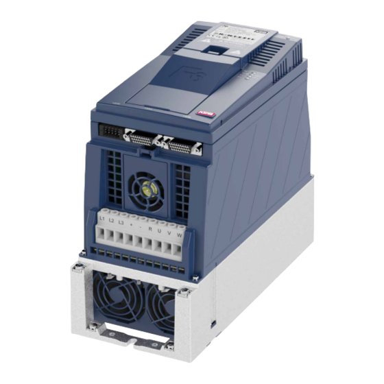
DeSCRIPTION OF THe CONTROL 2 Control 2.1 Description of the control The control board provides the following functions: • Digital and analog inputs and outputs • Serial diagnostic interface for connection to a PC • Hardware of the control circuit „safety separated“ according to EN 61800-5-1 •... -
Page 16: Overview Of The Connection And Control Elements
OVeRVIeW OF THe CONNeCTION AND CONTROL eLeMeNTS 2.2 Overview of the connection and control elements Temperature monitoring, brake control and monitoring, digital temperature and position detection Control terminal block for digital inputs/outputs; 24V supply; relay output; analog inputs and outputs Safety module Encoder interface channel A FS ST Encoder interface channel B Diagnostic interface with... -
Page 17: Motor Monitoring X1C (Temperature, Brake)
OVeRVIeW OF THe CONNeCTION AND CONTROL eLeMeNTS 2.2.1 Motor monitoring X1C (temperature, brake) The terminal block X1C is a 10-pole, pluggable terminal block with spring-cage connec- tion. It contains: • 2 outputs for control of 24V motor brakes • 2 control inputs for brakes or relays •... -
Page 18: Rotary Coding Switches (S1, S2) - In Preparation
OVeRVIeW OF THe CONNeCTION AND CONTROL eLeMeNTS 2.2.8 Rotary coding switches (S1, S2) - in preparation - If the CAN protocol is active, the rotary coding switches S1 (low byte) and S2 (high byte) define the node ID. If both switches are set to "0" or a faulty node ID is set, the node ID from fb64 is active. 2.2.9 Status LeDs 2.2.9.1 Boot display Before the LEDs start their normal function, they signal the boot procedure after switch- ing on:... -
Page 19: Dev St - Led
CONNeCTION OF THe CONTROL 2.2.9.4 DEV ST - LED DeV ST LeD colour Description Device off or booting. Error yellow no error, DC link not loaded. green no error, ready for operation. flashing green no error, is used for identification of the unit (fb32). Table 5: LED function DEV-ST 2.2.9.5 OPT - LED LeD colour Description reserved for options. -
Page 20: Assembly Of The Wires To Push In Terminals
OVeRVIeW OF THe CONNeCTION AND CONTROL eLeMeNTS 2.3.1 Assembly of the wires to PUSH IN terminals ATTENTION Malfunctions caused by loose cable connections! ► Observe metal sleeve length and stripping length Metal sleeve Stripping Cross-section Wire-end ferrule length length 0.50 mm 10 mm 12 mm with plastic collars... -
Page 21: Assignment Of The Terminal Strip X2A
ASSIGNMeNT OF THe TeRMINAL STRIP X2A 2.4 Assignment of the terminal strip X2A Name Description DI1 / AN3 Digital input 1 / analog input 3 (switchable via software) Digital input 2 Digital input 3 Digital input 4 Digital input 5 Digital input 6 Digital input 7 (fast input =>... -
Page 22: Voltage Output Of The Control Terminal Block
ASSIGNMeNT OF THe TeRMINAL STRIP X2A 2.4.1 Voltage output of the control terminal block Name 24Vout Function DC voltage output (SELV) to control the digital inputs minimum P24Vin - 3 V Output voltage maximum P24Vin permissible total current 100 mA (short-circuit proof) Table 8: Voltage output of the control 2.4.2 Connection and specification of the digital inputs... -
Page 23: Connection And Specification Of The Digital Outputs
ASSIGNMeNT OF THe TeRMINAL STRIP X2A 2.4.3 Connection and specification of the digital outputs Name DO1…DO2 Number Type 24 V high-side switch Classification in accordance with DIN EN 61131-2 minimum P24Vin - 3 V Output voltage maximum P24Vin permissible output current 100 mA per output (short-circuit proof) only ohmic load;... -
Page 24: Specification And Connection Of The Analog Inputs
ASSIGNMeNT OF THe TeRMINAL STRIP X2A The relay output of the control card Pro is available in two different versions. Material number of COMBIVERT xxF6Pxx-xxyx Relay (y=0-3) Positively driven relay (y=4, 5) Name - in preparation - (only control by safety modul) X2A.14 NO contact NO contact... -
Page 25: Figure 7: Examples For The Connection Of The Digital Outputs At X2A
ASSIGNMeNT OF THe TeRMINAL STRIP X2A 20 22 0…±20mA 0…±10Vdc 4…20mA *) Equipotential bonding conductor Figure 7: Examples for the connection of the digital outputs at X2A Attention No potential separation of the analog inputs to the control voltage ! Malfunction or defect caused by voltage differences. -
Page 26: Specification And Connection Of The Analog Output
ASSIGNMeNT OF THe TeRMINAL STRIP X2A 2.4.6 Specification and connection of the analog output Analog output Terminal X2A.22 0V reference voltage for analog output Terminal X2A.21 DC voltage output 0.0…10 V (≙ 0…100 % output value) minimum load impedance 1 kΩ Classification according to IEC 61131-2 Table 14:... -
Page 27: Voltage Supply
ASSIGNMeNT OF THe TeRMINAL STRIP X2A 2.4.7 Voltage supply 2.4.7.1 Voltage output 24VoutCtrl (X2A.26) As soon as the COMBIVERT is supplied with mains voltage, the output provides the voltage. The voltage output may only be used to supply the control board. Name Notes Output voltage:... -
Page 28: Mixed Voltage Supply
ASSIGNMeNT OF THe TeRMINAL STRIP X2A The supply of the device with control board Pro can be external, internal or mixed. external supply The external power supply is provided by a power supply unit according to the calculat- ed current consumption at the terminals X2A.27 und X2A.28. Name Notes Reference potential for... -
Page 29: Figure 12: Mixed Voltage Supply Of The Control
ASSIGNMeNT OF THe TeRMINAL STRIP X2A NOTICE Install protective diode. ► The diode D1 prevents the voltage output from supplying other loads if the external supply fails. Name Notes X2A.26 24VoutCtrl Voltage output Reference potential for X2A.27 P24Vin X2A.28 P24Vin Voltage input Figure 12: Mixed voltage supply of the control... -
Page 30: Terminal Block X2B
TeRMINAL bLOCk X2b 2.5 Terminal block X2b The terminal block X2B based on the installed safety module. The 6th digit of the mate- rial number defines the installed safety module: Material number Safety module Type 5, STO, SBC, SS1-r, SS1-t, SLS, xxF6xyx-xxxx SSM, SMS, SLA, SDLC, SSR und Safety over EtherCAT®... -
Page 31: Diagnosis/Visualisation
DIAGNOSIS/VISUALISATION 2.6 Diagnosis/visualisation The integrated serial interface provides the following functions: • Parameterization of the unit with the KEB software COMBIVIS • Connection of a control operator • DIN66019II is used as communication protocol. Interface Specification RS485 Common-mode voltage range 0…12 V... -
Page 32: Data Cable Rs232 Pc To Inverter
DIAGNOSIS/VISUALISATION 2.6.2 Data cable RS232 PC to inverter 0058025-001D Figure 14: Serial cable for the connection to a PC 2.6.3 USb-serial converter The USB-serial converter is used for the connection of drive converters, operators or IPC controls with DIN66019 interface or HSP5 interface at the USB port of PCs. The USB-serial converter is internal electrically isolated. -
Page 33: Fieldbus Interfaces
FIeLDbUS INTeRFACeS 2.7 Fieldbus interfaces The 10th digit of the material number shows whether an Ethernet fieldbus interface is equipped additionally to the CAN bus. Material number Ethernet fieldbus interface xxF6Pxx-xxyx 4, 5 integrated The active fieldbus interface is defined with fb68. The meaning of the light pattern of the status LED "NET ST" changes accordingly. 2.7.1 etherCAT 2.7.1.1 EhterCAT IN (X4B) and EtherCAT OUT (X4C) Function Top view Name Description Bus speed (yellow) No connection or deactivated EtherCAT IN... -
Page 34: Figure 16: Blink Code „Net St" - Led In Mode Ethercat
FIeLDbUS INTeRFACeS blink code NeT ST - LeD (red/green combination) Status blink code Description INIT Device in state INITIALISATION Pre-Op Device in state PRE-OPERATIONAL (50 ms-Raster) Safe-Op g-0-0-0-0-0 Device in state SAFE-OPERATIONAL (200 ms-Raster) Device in state OPERATIONAL, no error (dauernd) ERROR Communication or device error... -
Page 35: Encoder Interfaces
eNCODeR INTeRFACeS 2.8 encoder interfaces The 10th digit of the material number indicates which encoder interface is installed in the device. Material number Encoder interface 0, 4 without xxF6Pxx-xxyx 1, 3 Multi encoder interface 2.8.1 Multi-encoder-Interface The multi encoder interface is configured in dual-channel technique. Channel A supports the following encoder types: •... -
Page 36: Input Signals
eNCODeR INTeRFACeS 2.8.1.2 Input signals 360° mechanically / increments per revo- lution typically 1Vpp Cos+ - Cos- typically 1Vpp Sin+ - Sin- 360° mechanically = 360° electronically Sin_abs+ - Sin_abs- typically 1Vpp Cos_abs+ - Cos_abs- typically 1Vpp N+ - N- 0.2…1.2Vpp digital position of for example Endat or... -
Page 37: Table 22: Assignment Of X3A/X3B Depending On The Adjusted Encoder Interface
eNCODeR INTeRFACeS (front view encoder connector) X3A / X3B: D-Sub 26-pole (HD), triple row Plug-in connector-socket Counterpart: D-Sub 26-pole (HD), triple row, Plug-in connector with fixing bolts UNC 4.40 encoder Channel A / B A / B COS+ COS+ COS+ A+ (out) COS- COS- COS- A-(out) SIN+... -
Page 38: Description Of The Encoder Interfaces
eNCODeR INTeRFACeS 2.8.1.3 Description of the encoder interfaces Signals Only channel A: Input for two sine-wave, shifted by 90° differential signals with U =1 V, maxi- mum 200 kHz. single-ended (e.g. Cos+ against GND): Constant component 2.5 V ±0.5 V Differential (e.g. -
Page 39: Table 23: Encoder Specifications
eNCODeR INTeRFACeS Signals Output supply voltage for encoder: 8, 9 5,25 V 5.25 V +5 %/ -10 % max. 500 mA total (250 mA per channel) Output supply voltage for encoder: =24 V max. 500 mA total (250 mA per channel) 24 V •... -
Page 40: Brake Control And Temperature Detection
2.9 brake control and temperature detection Name Notes Brake control / output Brake control / output for supply of the feedback inputs P24Vin - 0.5 V / max. 1 A 24Vout (BR+ and 24Vout in addition 2 A) DIBR1 feedback input for brake control DIBR2 feedback input for... -
Page 41: Specification And Connection Of The Temperature Detection
2.9.2 Specification and connection of the temperature detection DANGeR Use only sensors with safe isolation ! Danger to life due to electric shock ! NOTICE Malfunctions due to incorrect cable or laying! Malfunctions of the control due to capacitive or inductive coupling. ►... -
Page 42: Connection Of A Kty Sensor
2.9.2.2 Connection of a KTY sensor NOTICE No protection of the motor winding in case of wrong connection. ► Operate KTY sensors in forward direction. Non-observance leads incorrect measurement in the upper temperature range. ► KTY sensors may not be combined with other detections. Name TA1 (X1C.9); TA2 (X1C.10) Function... -
Page 43: Figure 20: Connection Examples Of Different Temperature Sensors
Thermal contact (NC contact) ① Temperature sensor (PTC) or PT1000 ① Mixed sensor chain ① Legend Connection via shield plate (if not available, place on the mounting plate). Figure 20: Connection examples of different temperature sensors... -
Page 44: Revision History
ReVISION HISTORy 3 Revision History Version Date Description 2018-12 Completion of pre-series 2019-07 Completion of series version 2019-08 Values for temperature input fixed; editorial changes 2020-05 Editorial changes; Notes for positively driven relay inserted; CAN interface in preparation... - Page 45 CEP 13569-430 Portal do Sol, São Carlos Brazil Gangnam Gu 135- 757 Seoul Republic of Korea Tel: +55 16 31161294 E-Mail: roberto.arias@keb.de Tel: +82 2 6253 6771 Fax: +82 2 6253 6770 E-Mail: vb.korea@keb.de KEB Automation GmbH Czech Republic KEB RUS Ltd.
- Page 46 Automation with Drive www.keb.de KEB Automation KG Suedstrasse 38 32683 Barntrup Tel. +49 5263 401-0 E-Mail: info@keb.de...
Need help?
Do you have a question about the COMBIVERT F6 and is the answer not in the manual?
Questions and answers