KEB COMBIVERT F6 Instructions For Use Manual
Hide thumbs
Also See for COMBIVERT F6:
- Programming manual (544 pages) ,
- Reference manual (305 pages) ,
- Instructions for use manual (88 pages)

Related Manuals for KEB COMBIVERT F6


Summary of Contents for KEB COMBIVERT F6
- Page 1 COMBIVERT F6 INSTRUCTION FOR USE | INSTALLATION F6 HOUSING 2 ELEVATOR Document 20337008 US 00 Preliminary Version...
-
Page 3: Preface
The hardware and software described in this document are products of KEB. The infor- mation contained in this document is valid at the time of publishing. KEB reserves the right to update this document in response to misprints, mistakes or technical changes. -
Page 4: More Symbols
Preface More symbols Definition Symbol ► Action Step ● Enumerations or Unordered List Cross-reference QR-Code General Mandatory Action Mandatory: Refer to Instruction Manual Mandatory: Wear Ear Protection Warning Warning: Risk of Electric Shock Warning: Explosive Environments Warning: Forklift Truck and Other Industrial Vehicles Warning: Hot Surfaces Warning: Flammable Materials Warning: Overhead Obstacle... -
Page 5: Laws And Guidelines
Preface Laws and guidelines KEB Automation KG confirms with the EC declaration of conformity and the CE mark on the device nameplate that it complies with the essential safety requirements. The EC declaration of conformity can be downloaded on demand via our website. -
Page 6: Table Of Contents
Table of ConTenTs Table of Contents Preface ..............................3 Signal words and symbols ......................3 More symbols ..........................4 Laws and guidelines ........................5 Warranty and liability ........................5 Support ............................5 Copyright ............................5 Table of Contents ........................... 6 list of figures ............................9 list of Tables ............................ - Page 7 4.2.3 Control cabinet ventilation ....................50 4.2.4 Airflow of the drive converter ....................51 5 Installation and connection ........52 5.1 overview of the CoMbIVeRT f6 ....................52 5.2 Connection of the power unit ....................... 55 5.2.1 Connection of the voltage supply ..................55...
- Page 8 Table of ConTenTs 5.2.2 Protective and high frequency ground ................56 5.2.2.1 Protective earth (ground) ....................56 5.2.2.2 High frequency earth ground ................... 57 5.2.2.3 AC supply 3-phase ......................58 5.2.2.4 Supply conductors ......................58 5.2.2.5 Note on hard power systems ................... 59 5.2.3 DC connection ........................59 5.2.3.1 Terminal block X1A DC connection .................
-
Page 9: List Of Figures
lIsT of fIGURes list of figures Figure 1: Model number ..........................25 Figure 2: Nameplate ............................26 Figure 2: Nameplate ............................26 Figure 3: Switch-off time t depending on the overload I/IN at OC level 240 % ..........33 Figure 4: Typical overload characteristics in the lower output frequencies (OL2) example device size 10 35 Figure 5: Switch-off time t depending on the overload I/IN at OC level 240 % .......... -
Page 10: List Of Tables
lIsT of Tables list of Tables Table 1: Climatic environmental conditions ....................27 Table 2: Mechanical environmental conditions ..................28 Table 3: Chemical / mechanical active substances ................... 28 Table 4: Device classification ........................29 Table 5: Electromagnetic compatibility ....................... 29 Table 6: Overview of the 230V device data .................... -
Page 11: Glossary
International standard Degree of protection (xx for level) tance IP xx American wire gauge KEB product The KEB product is subject of this Business-to-business manual Open source real-time interface for Silicium temperature sensor (pola- Biss... - Page 12 Glossary Pulse width modulation Modular connector with 8 pins rJ45 Synchronous sensorless closed loop Safety Extra Low Voltage (< 60 V) sElV The safety integrity level is a measu- re for quantifying the risk reduction. Term used in the safety technology (EN 61508 -1...7) Synchronous serial interface for encoder...
-
Page 13: Standards For Drive Controllers
sTaNDarDs For DrIVE CoNTrollErs Standards for drive controllers Product standards that apply directly to the drive controller EN 61800-2 Adjustable speed electrical power drive systems - Part 2: General requirements - Rating specifications for low voltage adjustable frequency a.c. power drive systems (VDE 0160-102, IEC 61800-2) EN 61800-3 Speed-adjustable electrical drives. -
Page 14: Standards That Are Used In The Environment Of The Drive Controller
sTaNDarDs For DrIVE CoNTrollErs EN 61000-4-2 Electromagnetic compatibility (EMC) - Part 4-2: Testing and measurement techniques - Electrostatic discharge immunity test (IEC 61000-4-2); German version EN 61000-4-2 EN 61000-4-3 Electromagnetic compatibility (EMC) - Part 4-3: Testing and measurement techniques - Radiated, radio-frequency, electromagnetic field immunity test (IEC 61000-4-3);... - Page 15 sTaNDarDs For DrIVE CoNTrollErs EN 61373 Railway applications - Rolling stock equipment - Shock and vibration tests (IEC 61373); German version EN 61373 EN 61439-1 Low-voltage switchgear and controlgear assemblies - Part 1: General rules (IEC 121B/40/CDV); German version FprEN 61439-1 DIN EN 60939-1 Passive filter units for electromagnetic interference suppression - Part 1: Generic specification (IEC 60939-1:2010);...
-
Page 16: Basic Safety Instructions
► Read the instructions for use. ► Observe the safety and warning instructions. ► If instructions are unclear, please contact KEB prior to operating device. 1.1 target group This instruction manual is determined exclusively for electrical personnel. Electrical per- sonnel for the purpose of this instruction manual must have the following qualifications: •... -
Page 17: Installation
Basic safety instructions NOTICE Drive controllers contain electrostatic sensitive components. ► Avoid contact. ► Wear ESD-protective clothing. Do not store drive controllers • in the environment of aggressive and/or conductive liquids or gases. • with direct sunlight. • outside the specified environmental conditions. 1.3 installation DanGer risk of serious injury or death due to explosive environment! -
Page 18: Electrical Connection
If ground fault protection is required during installation of the system, suitable protective devices must be used for drive controllers. www.keb.de/fileadmin/media/Techinfo/dr/tn/ti_dr_tn-rcd-00008_en.pdf Installations which include drive controller shall be equipped with additional control and protective devices in accordance with the relevant applicable safety requirements, e.g. -
Page 19: Emc-Compatible Installation
1.4.2 Voltage test The KEB Elevator drive is dielectric-tested after assembly as part of the factory end test routine. This dielectric test is harmonized and in accordance with the requirements set forth in UL 61800, CSA C22.2 No. 274-17, ASME A17.5-2019, CSA B44.1-19, EN81, IEC 61800-5 and EN 60204-1. -
Page 20: Insulation Measurement
EN 60204-1 states that it is permissable to disconnect already tested components, such as the KEB elevator drive, because it has been 100% factory tested. This is the recommended approach. However, if subsequent testing is required in the integrated system (control panel), the following points must be observed: •... -
Page 21: Maintenance
For applications that require cyclic switching off and on of the drive controller, maintain an off-time of at least 5 min after the last switch on. If you require shorter cycle times please contact KEB America. A disconnect switch must be provided as a means of turning off the supply voltage when the unit is not in use or when it must be serviced. -
Page 22: Disposal
► The function of the drive controller is dependent on its parameteri- zation. Never replace without knowledge of the application. ► Modification or repair is permitted only by KEB Automation KG or KEB America Inc. authorized personnel. ► Only use original manufacturer parts. -
Page 23: Product Description
Restriction The product is not permitted to be used for vital life sustaining applications, i.e. medical, without the express written consent of KEB Automation KG or KEB America Inc. general management. 2.1.1 Residual risks... -
Page 24: Product Features
• Operation of three-phase asynchronous motors and three-phase synchronous mo- tors, in operating modes open-loop or closed-loop with and without speed feedback • Supports: CAN DS417 lift control and KEB DIN 66019 II lift protocol • System-overlapping operating concept • Wide operating temperature range •... -
Page 25: Model Number
Connection Type Housing 2…9 Equipment 5: Safety module type 5 Control Type P: PRO Series COMBIVERT F6 Inverter Size 10…29 Figure 1: Model number CANopen ® is registered trademark of CAN in AUTOMATION - International Users and Manufacturers Group e.V. -
Page 26: Nameplate
Manufacturer identification Technical data input Technical data output Model number, basic device ( 2.4 Model Number), KEB order number Configurable options or customer material number/version ( 2 Product Description) Barcode Interleaved 2/5 (serial number) Serial-, order number; Year and week of production; Factory... -
Page 27: Technical Data
Operating cOnditiOns 3 technical data Unless otherwise indicated, all electrical data in the following chapter refer to a 3-phase AC mains. 3.1 Operating conditions 3.1.1 climatic environmental conditions storage standard class descriptions Ambient temperature EN 60721-3-1 -25…55 °C Relative humidity EN 60721-3-1 5…95 % (without condensation) Storage height... -
Page 28: Mechanical Environmental Conditions
Operating cOnditiOns 3.1.2 Mechanical environmental conditions storage standard class descriptions Vibration amplitude 1.5 mm (2…9 Hz) Vibration limits EN 60721-3-1 Acceleration amplitude 5 m/s² (9…200 Hz) Shock limit values EN 60721-3-1 40 m/s²; 22 ms transport standard class descriptions Vibration amplitude 3.5 mm (2…9 Hz) Vibration limits EN 60721-3-2 Acceleration amplitude 10 m/s²... -
Page 29: Electrical Operating Conditions
Operating cOnditiOns 3.1.4 electrical operating conditions 3.1.4.1 Device classification requirement standard class descriptions Overvoltage category EN 61800-5-1 – Non-conductive pollution, occasional conden- Pollution degree EN 60664-1 sation when PDS is out of service table 4: Device classification 3.1.4.2 Electromagnetic compatibility For devices without an internal filter, an external filter is required to comply with the following limits. -
Page 30: Device Data Of The 230V Devices
Device Data of the 230v Devices 3.2 Device data of the 230v devices 3.2.1 overview of the 230v devices The recommended motor power applies to 4/6-pole standard motors. When using mo- tors with different numbers of poles, the inverter must be dimensioned based on the rated motor current and rated motor frequency. -
Page 31: Voltage And Frequencies For 230V Devices
Device Data of the 230v Devices Device size housing Max. braking current 21.5 33.6 B_max Min. braking resistor value / Ω B_min S1 operation: Max. cycle time: 120 s; Max c.d.f.: 50 % Braking transistor S3 operation: Max. cycle time: 120 s; Max c.d.f.: 70 % Protective function for braking transistor No protection function available table 6:... -
Page 32: Example Of The Calculation Of The Possible Motor Voltage
Device Data of the 230v Devices 3.2.2.1 Example of the calculation of the possible motor voltage: The motor voltage for dimensioning of the drive is depending on the used components. The motor voltage can be reduced according to the following table: component Reduction / % example... -
Page 33: Figure 3: Switch-Off Time T Depending On The Overload I/In At Oc Level 240
Device Data of the 230v Devices Restrictions: • The thermal design of the heat sink is based on the rated operation. The follow- ing values are taken into account: Rated output current, ambient temperature, rated switching frequency, and rated voltage. •... -
Page 34: Frequency-Dependent Maximum Current (Ol2) For 230V Devices
Device Data of the 230v Devices Operation in the range of the thermal overload limit Due to the steep slope of the overload characteristic, the duration of a permissible over- load in this range cannot be determined exactly. Therefore, the design of the drive con- troller should be assumed to have a maximum overload time no greater than 300s. -
Page 35: Figure 4: Typical Overload Characteristics In The Lower Output Frequencies (Ol2) Example Device Size 10
Device Data of the 230v Devices Output frequency / Hz Legend Overcurrent I Software current limit I (the limit can be set with parameter LC30) Switching frequency 2 kHz Switching frequency 4 kHz Switching frequency 8 kHz Switching frequency 16 kHz Not available for modulation. -
Page 36: Power Dissipation At Rated Operation Of The 230V Devices
Device Data of the 400v Devices Frequency-dependent maximum current Device size output frequency / hz 12.5 2 kHz 23.8 23.8 23.8 23.8 23.8 23.8 4 kHz 22.0 23.8 23.8 23.8 23.8 23.8 frequency-dependent maximum out_max current @ f 8 kHz 19.0 23.8 23.8... -
Page 37: Table 16: Overview Of The 400V Device Data
Device Data of the 400v Devices Device size housing Rated input current in_UL = 480V / MΩ Insulation resistance @ U = 500 V > 20 Output voltage 0...U Output frequency / Hz 0...599 Output phases Rated output current 16.5 = 400V Rated output current N_UL... -
Page 38: Voltage And Frequencies For 400V Devices
Device Data of the 400v Devices 3.3.2 voltage and frequencies for 400v devices input voltages and frequencies Rated input voltage Rated mains voltage (North America) N_UL Input voltage range 280...550 Input phases Mains frequency / Hz 50 / 60 Mains frequency tolerance ±... -
Page 39: Overload Characteristic (Ol) For 400V Devices
Device Data of the 400v Devices Device size Rated output current @ U = 400V 16.5 Rated output current @ U = 480V N_UL N_UL Rated output overload (60 s) 150 IN / 177 IN_UL 3.3.3.1 Overload characteristic (OL) Overload current for 400V devices Software current limit... -
Page 40: Frequency-Dependent Maximum Current (Ol2) For 400V Devices
Device Data of the 400v Devices Overload characteristic (OC level 240%) ① ② Motor current / drive controller rated currrent / % Legend Thermal overload limit Limitation by the torque limit (the limit can be set with parameter LC30) figure 5: Switch-off time t depending on the overload I/IN at OC level 240 % •... - Page 41 Device Data of the 400v Devices The elevator drive is preset so that if the maximum current is exceeded at low frequen- cies, the switching frequency is automatically reduced step-by-step until the lowest level is reached. The following characteristic curve indicates the permissible maximum current for the output frequency values 0 Hz, 3.1 Hz, 6.2 Hz, 12.5 Hz, 25 Hz and 50 Hz.
-
Page 42: Power Dissipation At Rated Operation Of The 400V Devices
GeneRaL eLectRicaL Data Device size output frequency / hz 12.5 2 kHz 39.6 39.6 39.6 39.6 39.6 39.6 4 kHz 39.6 39.6 39.6 39.6 39.6 frequency-dependent maximum current @ f out_max 8 kHz 39.6 39.6 39.6 39.6 39.6 16 kHz 18.9 35.9 38.9 39.6 39.6 table 23: Frequency-dependent maximum current for device size 14... -
Page 43: Switching Frequency And Temperature Of The 230V Devices
GeneRaL eLectRicaL Data 3.4.1.1 Switching frequency and temperature of the 230V devices Device size 8 for S1 4 for S1 Rated switching frequency / kHz 8 for S3 Lift 8 for S3 Lift Max. switching frequency / kHz S_max Min. switching frequency / kHz S_min / °C... -
Page 44: Dc Link / Braking Transistor Function Of The 230V Devices
GeneRaL eLectRicaL Data DC link Inverter Rectifier Motor Braking transistor Braking resistor figure 7: Block diagram of the energy flow 3.4.2.1 DC link / braking transistor function of the 230V devices Device size Rated DC link voltage N_dc = 230V Rated DC link voltage N_dc_UL = 480V... -
Page 45: Dc Link / Braking Transistor Function Of The 400V Devices
GeneRaL eLectRicaL Data 3.4.2.2 DC link / braking transistor function of the 400V devices Device size Rated DC link voltage N_dc = 400V Rated DC link voltage N_dc_UL = 480V N_UL DC link voltage working voltage range 390...780 IN_dc DC switch-off level "ERROR underpotential“ DC switch-off level "ERROR overpotential“... -
Page 46: Switching Behaviour Of The Fans
GeneRaL eLectRicaL Data 3.4.3.1 Switching behaviour of the fans The fans have different switch-on and switch-off points. The switching point for the switch-on temperature is not adjustable. The hysteresis for the switch-off temperature cannot be changed. The switching behaviour of the fans depends on the heat sink and interior temperature. -
Page 47: Installation
Dimensions anD weights 4 installation 4.1 Dimensions and weights 4.1.1 air-cooled panel mount version für M6 for M6 für M6 for M6 housing Weight 5 kg Dimensions All dimensions in mm Figure 9: Dimensions panel mount air-cooled... -
Page 48: Control Cabinet Installation
Use of other fasteners ► Alternatively selected mounting hardware must meet the above material characteristics (quality) and tightening torques! ► The use of other mounting hardware is beyond the control of KEB and is therefore the sole responsibility of the customer. -
Page 49: Mounting Distances
Control Cabinet installation 4.2.2 mounting distances For power dissipation for the control cabinet dimension, refer to 3.2.4 Power dissipa- tion at rated operation of the 230V devices 3.3.4 Power dissipation at rated oper- ation of the 400V devices. A lower value can be used here depending on the operating mode/load. -
Page 50: Control Cabinet Ventilation
Control Cabinet installation 4.2.3 Control cabinet ventilation If, due to the design, external cabinet cooling fans must be used, appropriate filters must be installed to prevent airborn contamination from being blown into the control cabinet and ultimately the drive controller. The filters must be checked, cleaned or replaced, per a regular maintenance schedule. -
Page 51: Airflow Of The Drive Converter
Control Cabinet installation 4.2.4 Airflow of the drive converter ① ② ③ ⑥ ④ ⑤ legend Airflow direction Interior fan (from housing 4) Drive converter (power unit and control) Drive converter (heat sink) Interior fan for (housing 2 and 3) Heatsink fan Housing (e.g. -
Page 52: Installation And Connection
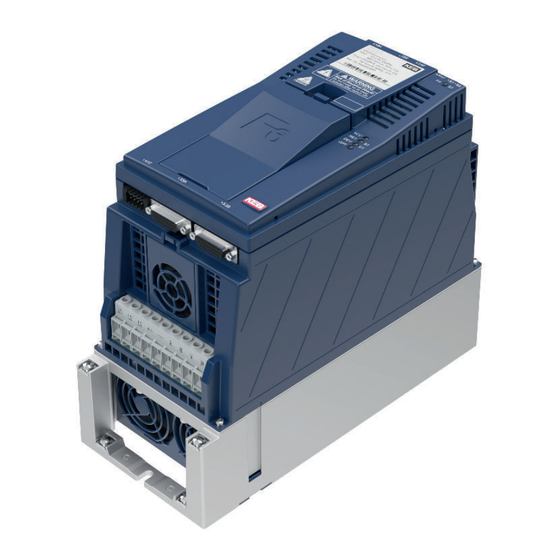
Overview Of the COMBivert f6 5 installation and connection 5.1 Overview of the COMBivert f6 housing 2 Name Description Fixing points for the optional shielding plates. The shielding e.g. from the motor cable is laid on the mounting plate in the control cabinet or on the shield connection braket (optionally available). -
Page 53: Figure 14: F6 Housing 2 Lift Front View
Overview Of the COMBivert f6 housing 2 Name Description Power circuit terminals for: • Mains input • Braking resistor • DC supply • Motor connection Protective earth; all protective earth (ground) termi- nals may only have one conductor installed. Fixing points for the optional shielding plates. -
Page 54: Figure 15: F6 Housing 2 Lift Rear View With Control Board Lift
Overview Of the COMBivert f6 housing 2 Name Description Fieldbus Interface Ethernet 12 13 14 Fieldbus Interface Serial RS485 Safety module Connection for: • CAN bus • Analog inputs and analog output • Digital inputs and outputs • 24 V DC voltage supply figure 15: F6 housing 2 Lift rear view with control board LIFT Further information can be found in the respective control board manual. -
Page 55: Connection Of The Power Unit
ConneCtion of the power unit 5.2 Connection of the power unit NOTICE Destruction of the drive controller! ► Never exchange mains input and motor output! 5.2.1 Connection of the voltage supply The F6 housing 2 can be supplied from the mains. The charging current limiting is locat- ed before the DC link. -
Page 56: Terminal Block X1A
ConneCtion of the power unit 5.2.1.1 Terminal block X1A Cross-section for tightening Max. number name function torque of conductors terminal connection Mains connection 3-phase Flexible cable with wire-end ferrule DC terminals with plastic collars 0.5...16 mm² For IEC: 2 1.5 Nm For 2 conductors 0.5mm...6mm²... -
Page 57: High Frequency Earth Ground
The use of the high frequency ground is not required if the drive control is prop- erly mounted and wired according to the KEB EMC guidelines. The protective earth ground must always be green, white or gray per NEC and/ or CEC guidelines. -
Page 58: Ac Supply 3-Phase
ConneCtion of the power unit 5.2.2.3 AC supply 3-phase ① ② ③ ④ ⑤ ⑥ type Description Mains phase 3-phase TN, TT The rated voltage between one phase conductor and earth potential (or the Mains form neutral point in the IT system) must not exceed 300V, UL/CSA: 480 / 277 V. -
Page 59: Note On Hard Power Systems
80-100% THiD to around 45% THiD. If lower values of line current distortion are required, contact KEB regarding an applicable harmonic filter. With such a device, it is possible to reduce the harmonic distortion below 8% THiD. -
Page 60: Terminal Block X1A Dc Connection
ConneCtion of the power unit 5.2.3.1 Terminal block X1A DC connection Cross-section for tightening Max. number of name function torque conductors terminal connection Flexible cable with wire-end ferrule with plastic collars 0.5...16 mm² For IEC: 2 1.5 Nm For 2 conductors 0.5mm...6mm² DC terminals 13 Ib inch For UL/CSA: 1... -
Page 61: Wiring Of The Motor
➀ ➃ Control P A/K Legend KEB COMBIVERT Apply motor cable, shielding on both sides over a large surface on the bare metallic frame or mounting plate (remove paint if necessary) Three-phase motor Instructions for use "Control circuit“ Temperature monitoring (optional) ... -
Page 62: Terminal Block X1A Motor Connection
ConneCtion of the power unit 5.2.3.3 Terminal block X1A motor connection Cross-section for tightening Max. number name function torque of conductors terminal connection Flexible cable with wire-end ferrule with plastic collars 0.5...16 mm² For IEC: 2 1.5 Nm For 2 conductors 0.5mm...6mm² Motor connection 13 Ib inch For UL/CSA: 1... -
Page 63: Motor Cable Cross-Section And Installation
ConneCtion of the power unit Max. motor cable length shielded (low capacitance) Drive size/voltage 10/230V & 14/400-480V Limit class in accordance with 61800-3 Filter 14E6T60-1050 14E6T60-3000 14E6T60-1050 14E6T60-3000 Motor cable length @ f = 2 khz 50 m 50 m 100 m 100 m Motor cable length @ f... -
Page 64: Interconnection Of The Motor
ConneCtion of the power unit 5.2.3.7 Interconnection of the motor NOTICE protect motor against voltage peaks! ► In some conventional installations and many MRL applications, the motor can be a considerable distance (greater than 15m) from the elevator drive. Under these circumstances the long cable length, coupled with high dv/dt phase to phase motor votlage, can cause high voltage peaks at the motor terminals. -
Page 65: Figure 22: Terminal Block X1C For Control Board Pro
ConneCtion of the power unit name Description Brake control / output + Brake control / output - For supply of the checkback inputs 24Vout DIBR1 Checkback input 1 for brake and relay DIBR2 Checkback input 2 for brake and relay ―... -
Page 66: Fusing Of The Devices
ConneCtion of the power unit NOTICE no protection of the motor winding in case of wrong connection! ► Operate KTY sensors in forward direction. ► KTY sensors may not be combined with other sensors. For futher information regarding the wiring of temperature sensors and the brake control, please ... -
Page 67: Table 36: Fusing Of The 230 V Devices
ConneCtion of the power unit In PM synchronous motor applications where the drive input current can be significantly lower than the output current, it is allowed to use a protection device with a lower current rating thus being able to optimize line side wiring and ancillary components. Max. -
Page 68: Connection And Use Of A Braking Resistor
ConneCtion of the power unit 5.2.5 Connection and use of a braking resistor Risk of fire by using brake resistors ! CAution ► The risk of fire can be significantly reduced by using suitable moni- toring functions/circuits. Destruction of the frequency inverter if the value has fallen below NOTICE the minimum brake resistance value! ►... -
Page 69: Use Of Braking Resistors
ConneCtion of the power unit 5.2.5.2 Use of braking resistors Risk of fire or smoke emission in case of overload or error! wArninG use of braking resistors ► Failure to implement a braking resistor protection method along with the appropriate control circuitry can result in heat damage to the resistors, elevator controls, surrounding components in the machine room, and the risk of a catastrophic fire. -
Page 70: Brake Resistor Protection
ConneCtion of the power unit 5.2.5.3 Brake resistor protection A normally closed temperature sensor on the braking resistors can be used to open a DC contactor in the event the resistor temperature becomes excessive. Risk of catastrophic damage and/or fire! DAnGer ►... -
Page 71: Figure 27: Temperature Sensor Monitor Circuit; No Elevator Controller Supervision: Line Contactor
ConneCtion of the power unit Legend Branch Circuit Fuses Line Choke EMI EMI Filter Brake Resistor Line Contactor Elevator Control Voltage Control Motor figure 27: Temperature Sensor Monitor Circuit; No Elevator Controller Supervision: Line Contactor A normally closed temperature sensor on the braknig resistors can be used to open an AC line contactor in the event the resistor temperature becomes excessive. -
Page 72: Figure 28: Brake Transistor Monitor; No Elevator Controller Supervision
28: Brake Transistor Monitor; No elevator controller supervision: DC contactor The KEB brake transistor monitor module, part number 00f5090-Btw9, can be used to monitor the fuction of the brake transistor in cases where there is no temperature sen- sor installed on the braking resistors. When the brake transistor is functioning normally, the contact K1/K2 will be closed. -
Page 73: Accessories
80-100% THiD to around 45% THiD. ► If lower values of line current distortion are required, contact KEB regarding an applicable harmonic filter. With such a device it is pos- sible to reduce the harmonic distortion below 8% THiD. -
Page 74: Dv/Dt Chokes
ACCeSSorieS then the subsequent connection through the bearings to ground. The pulse width modu- lated (PWM) output of the drive interacts with the capacitive coupling causing leakage current to flow from the rotor through the bearings to the grounded motor frame. This ferrite core can be used to combat the flow of leakage current and thereby reduce the magnitude of current flowing though the bearings. -
Page 75: Certification
6.2 UL certification Acceptance according to UL is indicated on the name- plate of KEB drive converters by the logo shown below. For UL compliance for use in North American and Canadian markets, the following ad- ditional information must be observed on the market: •... -
Page 76: Further Information And Documentation
CertifiCation 6.3 Further information and documentation You find supplementary manuals and instructions for the download under: https://www.kebamerica.com/elevator-support/ General instructions • EMC and safety instructions Manuals for additional control boards, safety modules, fieldbus modules, etc. • Instruction and information for construction and development •... -
Page 77: Revision History
ReVision histoRy 7 Revision history Version Date Description 2024-02-06 Initial Release (Preliminary version) -
Page 78: Notes
NOTES Notes... - Page 79 / Mitjer, Nave 8 - Pol. Ind. LA MASIA E-Mail: info@keb.cz Internet: www.keb.cz 08798 Sant Cugat Sesgarrigues (Barcelona) Spain Tel: +34 93 8970268 Fax: +34 93 8992035 E-Mail: vb.espana@keb.de France Société Française KEB SASU Z.I. de la Croix St. Nicolas 14, rue Gustave Eiffel...
- Page 80 Automation with Drive www.kebamerica.com KEB America, Inc. 5100 Industrial Blvd. S. Shakopee, MN 55379 Tel. +1 952 2241400 E-Mail: info@kebamerica.com...
Need help?
Do you have a question about the COMBIVERT F6 and is the answer not in the manual?
Questions and answers