KEB COMBIVERT F5 Instructions For Use Manual
Hide thumbs
Also See for COMBIVERT F5:
- Applications manual (378 pages) ,
- Reference manual (349 pages) ,
- Instruction manual (196 pages)

Related Manuals for KEB COMBIVERT F5


Summary of Contents for KEB COMBIVERT F5
- Page 1 COMBIVERT F5/F6 INSTRUCTIONS FOR USE | INSTALLATION F5/F6 HOUSING V | 600...1000 KVA Translation of the original manual Document 20128815 EN 01...
-
Page 3: Preface
PreFAce Preface The described hard- and software are developments of the KEB Automation KG. The enclosed documents correspond to conditions valid at printing. Misprint, mistakes and technical changes reserved. Signal words and symbols Certain operations can cause hazards during the installation, operation or thereafter. -
Page 4: Laws And Guidelines
The customer may use the instruction manual as well as further documents or parts from it for internal purposes. Copyrights are with KEB Automation KG and remain valid in its entirety. Other wordmarks or/and logos are trademarks (™) or registered trademarks (®) of their... -
Page 5: Table Of Contents
TAbLe OF cONTeNTS Table of contents Preface ..............................3 Signal words and symbols ......................3 More symbols ..........................3 Laws and guidelines ........................4 Warranty ............................4 Support ............................4 Copyright ............................4 Table of contents ........................... 5 List of Figures ............................8 List of Tables ............................9 Glossar .............................. - Page 6 TAbLe OF cONTeNTS 4.2.2 Wiring diagram cooling system ..................28 4.3 Dimensions of the housing ......................29 4.4 Fixing points at the housing ......................30 4.5 Assembly aids ..........................31 4.6 Assembly in the control cabinet ....................33 4.6.1 Assembly of the slide rails and safety devices at the drive converter ........ 33 4.6.2 Function of the locking levers .....................
- Page 7 TAbLe OF cONTeNTS 6.3 electrical data 4000 V mains voltage ................... 64 7 Start-Up ................. 65 7.1 Procedure for initial start-up ......................65 7.2 Switch-on procedures ........................66 7.3 Diagram switch-on procedure ...................... 67 A Annex - Diagrams ............68 A.1 Overload characteristic ........................
-
Page 8: List Of Figures
LIST OF FIGUreS List of Figures Figure 1: Schematic diagram of the electrical power unit ............... 24 Figure 2: Interior ventilation......................25 Figure 3: Coolant connections of the drive converter..............27 Figure 4: Wiring diagram cooling system ..................28 Figure 5: Dimensions of the housing.................... -
Page 9: List Of Tables
LIST OF TAbLeS List of Tables Table 1: Part code..........................23 Table 2: Permissible cable cross-sections and tightening torques ..........47 Table 3: Temperature detection ..................... 55 Table 4: Functions temerature input ....................55 Table 5: Technical Data .........................63 Table 6: Electro-chemical voltage series .................. -
Page 10: Glossar
International standard Synchronous sensorless closed Inverter A loop Inverter B Synchronous serial interface for COMBIVERT KEB drive converters encoder COMBIVIS KEB start-up and parameterizing PT1000 Temperature sensor with software R0=1000Ω MTTF mean service life to failure PT100 Temperature sensor with R0=100Ω... - Page 11 GLOSSAr Term used in the safety technolo- gy (EN 61508-1...7) for the size of error probability Term used in the safety technolo- gy (EN 61508-1...7) for the size of error probability per hour Universal serial bus Inverter B...
-
Page 12: Standards For Drive Converters / Control Cabinets
STANDArDS FOr DrIVe cONVerTerS / cONTrOL cAbINeTS Standards for drive converters / control cabinets DGUV regulation 3 Electrical systems and equipment DIN 46228-1 Wire-end ferrules; Tube without plastic sleeve DIN 46228-4 Wire-end ferrules; Tube with plastic sleeve DIN IEC 60364-5-54 Low-voltage electrical installations - Part 5-54: Selection and erection of electrical equipment - Earthing arrangements, protective conductors and protec- tive bonding conductors... - Page 13 STANDArDS FOr DrIVe cONVerTerS / cONTrOL cAbINeTS EN 61439-1 Low-voltage switchgear and controlgear assemblies - Part 1: General rules (IEC 121B/40/CDV:2016); German version FprEN 61439-1:2016 EN 61508-1...7 Functional safety of electrical/electronic/programmable electronic safety-related systems – Part 1...7 (VDE 0803-1…7, IEC 61508-1…7) EN 61800-2 Adjustable speed electrical power drive systems - Part 2: General requirements - Rating specifications for low voltage adjustable frequency a.c. power drive...
-
Page 14: Basic Safety Instructions
Hazards and risks through ignorance. ► Read the instruction manual ! ► Observe the safety and warning instructions ! ► If anything is unclear, please contact KEB Automation KG ! 1.1 Target group This instruction manual is determined exclusively for electrical personnel. Electrical per- sonnel for the purpose of this instruction manual must have the following qualifications: •... -
Page 15: Installation
bASIc SAFeTy INSTrUcTIONS Drive converters contain electrostatic sensitive components. ► Avoid contact. ► Wear ESD-protective clothing. Do not store drive converters • in the environment of aggressive and/or conductive liquids or gases. • with direct sunlight. • outside the specified environmental conditions. 1.3 Installation DANGer Do not operate in an explosive environment! ►... -
Page 16: Electrical Connection
bASIc SAFeTy INSTrUcTIONS 1.4 electrical connection DANGer Voltage at the terminals and in the device ! Danger to life due to electric shock ! ► Never work on the open device or never touch exposed parts. ► For any work on the unit switch off the supply voltage and secure it against switching on. -
Page 17: Emc-Compatible Installation
Accordng to EN 60204-1 it is permissible to disconnect already tested com- ponents. Drive converters of the KEB Automation KG are delivered ex works voltage tested to 100% according to product standard. 1.4.3 Insulation measurement An insulation measurement (in accordance with EN 60204-1 chapter 18.3) with DC... -
Page 18: Start-Up And Operation
bASIc SAFeTy INSTrUcTIONS 1.5 Start-up and operation The drive converter must not be started until it is determined that the installation com- plies with the machine directive; Account is to be taken of 60204-1. WArNING Software protection and programming ! Hazards caused by unintentional behavior of the drive! ►... -
Page 19: Maintenance
For applications that require cyclic switching on and off of the drive converter, main- tain an off-time of at least 5 min. If you require shorter cycle times please contact KEB Automation KG. Short-circuit proof The drive converters are conditional short-circuit proof. After resetting the internal pro- tection devices, the function as directed is guaranteed. -
Page 20: Disposal
Drive converters with safety function are limited to a service life of 20 years. Then the devices must be replaced. Drive converters of the KEB Automation KG are professional, electronic devices exclu- sively for further industrial processing (so-called B2B devices). Thus the marking does not occur with the symbol of the crossed-out wheeled bin, but by the word mark and the date of manufacture. -
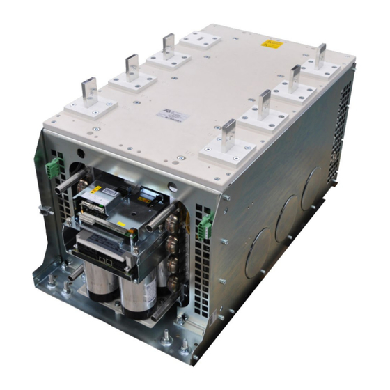
Page 21: Product Description
PrODUcT DeScrIPTION 2 Product Description The COMBIVERT F5 / F6 is a four quadrant drive converter.It consists of two inverters, which are connected internally via a DC link.The V housing has AC pre-charging which makes it possible to pre-charge another unit of the same size.The drive converter is designed for 400V / 690V mains. -
Page 22: Specified Application
The used semiconductors and components of the KEB Automation KG are developed and dimensioned for the use in industrial products. Restriction If the KEB COMBIVERT F5 is used in machines, which work under exceptional condi- tions or if essential functions, life-supporting measures or an extraordinary safety step must be fulfilled, the necessary reliability and security must be ensured by the machine builder. -
Page 23: Part Code
/ output encoder interface F6 control board with STO, multi software, multi en- coder interface, fieldbus EtherCAT F6 control board with STO, multi software, multi encoder interface, fieldbus Varan F5: COMBIVERT F5 Series F6: COMBIVERT F6 33: 600 kVA Inverter size 37: 980 kVA... -
Page 24: Functional Overview
FUNcTIONAL OVerVIeW 3 Functional Overview 3.1 Schematic diagram of the electrical power unit for the Q4 operation Fuses Mains fuses Pre-charging circuit HF filter AFE filters L3´ Drive converter L2´ Drive converter A L1´ Connection second Braking option DC link DC link Connection + /- Connection + /- Drive converter B... -
Page 25: Interior Ventilation
24 V DC voltage or 230 V AC voltage. A suitable fan with 24 V DC voltage is listed in the chapter Annex Accessories. This fan can be supplied via KEB (see „D.1.2 Internal fan“). Figure 2: Interior ventilation... -
Page 26: Mechanical Installation
MecHANIcAL INSTALLATION 4 Mechanical Installation 4.1 cooling system The KEB COMBIVERT in V housing is available exclusively for liquid cooling systems. The dissipation of the power loss must be ensured by the machine builder. ATTENTION Operation only with flow switch and flow monitor permissible. -
Page 27: Coolant Connections Of The Drive Converter
4.2.1 coolant connections of the drive converter Legend Coolant outlet Coolant outlet Coolant inlet Coolant inlet Figure 3: Coolant connections of the drive converter Screw connections for the coolant connection can be found at „D.1.3 Screw connection“. These are supplied by KEB as standard. -
Page 28: Wiring Diagram Cooling System
MecHANIcAL INSTALLATION 4.2.2 Wiring diagram cooling system This connection diagram serves only as an installation proposal and restores no professional planning and design! Housing V ② ③ ① ② ¾“ ¾“ ② ③ ② ① ¾“ ¾“ ➃ ➄ “ “... -
Page 29: Dimensions Of The Housing
MecHANIcAL INSTALLATION 4.3 Dimensions of the housing KEB Automation KG 32683 Barntrup Made in Germany Figure 5: Dimensions of the housing... -
Page 30: Fixing Points At The Housing
MecHANIcAL INSTALLATION 4.4 Fixing points at the housing 4xØ9 KEB Automation KG 32677 Barntrup Made in Germany 4xØ9 Front side Rear side Figure 6: Fixing points at the housing Alternative fixing points on the rear side.Note that in this mounting option, the access to the rear wall of the control cabinet must be guaranteed. -
Page 31: Assembly Aids
MecHANIcAL INSTALLATION 4.5 Assembly aids Two different tools, which can be ordered seperatly are available for the assembly of the unit in a control cabinet. There is a lifting device as assembly kit, as well as a eye bolt set size M12 DIN 580. Figure 7: Lifting device... -
Page 32: Figure 8: Eyebolts
MecHANIcAL INSTALLATION Figure 8: Eyebolts Assembly aids Assembly kit ring bolts M12 DIN 580 Item number 00F5ZTB-0004 Mounting kit hoisting device Item number 00F5ZTB-0013 Figure 9: Assembly aids... -
Page 33: Assembly In The Control Cabinet
G er m an 5, 6 5, 6 Figure 10: Assembly of the slide rails Pos. Description Keb Part number Torque 2x slide rails D0V6T09-0009 2x locking lever D0V6T09-0049 4x sheet metal bearing D0V6T09-0059 8x M5x 10mm oval-head screws ISO 7045 9905071-510K 4.0Nm... -
Page 34: Function Of The Locking Levers
MecHANIcAL INSTALLATION 4.6.2 Function of the locking levers The locking levers for securing the drive converter in the control cabinet can be opened or closed by moving the long front end. Locking lever open Locking lever closed Figure 11: Function of the locking levers... -
Page 35: Assembly Of The Side Guide Rails
They are the breakpoints for the drive converter in the control cabinet. Figure 12: Assembly of the side guide rails Pos. Description Keb Part number rittal Part number 1x angular rail left D0V6T09-000L 1x angular rail right... -
Page 36: Positions Of The Side Guide Rails In The Control Cabinet
MecHANIcAL INSTALLATION 4.6.4 Positions of the side guide rails in the control cabinet Decisive for the installation is the minimum dimension of 132 mm given above. This must not be lower, since otherwise the distances of the +/- rails of the DC link to the control cabinet housing are not met. -
Page 37: Figure 14: Distances
MecHANIcAL INSTALLATION 66,5 116,5 View from above View from above Upper fixing points of the drive converter Lower fixing points of the drive converter 66,5 41,5 A (1 : 2) Cross section through the control cabinet Cutout A Figure 14: Distances... -
Page 38: Installation Of The Drive Converter In The Control Cabinet
MecHANIcAL INSTALLATION 4.6.5 Installation of the drive converter in the control cabinet Schematic diagram The control cabinet shown in the following drawings is merely a section of the total system for better illustration. It is not a single control cabinet. Figure 15: Schematic diagram... -
Page 39: Figure 16: Transport
MecHANIcAL INSTALLATION ATTENTION Observe weight during transport ► The drive converter has a weight of 150 kg. ► The transport must be done only with approved lifting devices. It is recommended to assembly the drive converter into the control cabinet with a forklift or crane. -
Page 40: Figure 17: Connect The Drive Converter Housing V With The Control Cabinet
MecHANIcAL INSTALLATION WArNING Risk of tipping without fixed screw connection ! ► Provide sufficient stability for the control cabinet. ► Firmly fix to the ground or intergrate into a cabinet system. ► Avoid top-heaviness of the control cabinet. Procedures: 1. Place the drive converter with open locking levers to the control cabinet. 2. Place the drive converter on the guide rails. atio e in Barn... -
Page 41: Figure 18: Fix The Drive Converter Housing V In The Control Cabinet
MecHANIcAL INSTALLATION Procedures: 3. Push the drive converter slowly past the front vertical frame rails to the stopper of the opened locking levers into the control cabinet. 4. Close the locking levers by pressing them down. 5. Remove the lifting device. 6. -
Page 42: Figure 19: Drive Converter Housing V Assembled In The Control Cabinet
MecHANIcAL INSTALLATION The figure shows the drive converter housing V assembled in the control cabinet. B Au to ma 3 Ba n KG rn tru Figure 19: Drive converter housing V assembled in the control cabinet... -
Page 43: Disassembly From The Control Cabinet
MecHANIcAL INSTALLATION 4.7 Disassembly from the control cabinet Carry out the disassembly from the control cabinet in reverse order to the assembly. Screws which have been attached during the assembly, must be loosened at disas- sembly. -
Page 44: Electrical Installation
ATTENTION The applicable laws and local regulations must always be observed when planning and executing the installation. KEB assumes no liability for installations when laws, local and / or other regulations have not been complied. If the recommendations provided by KEB have been ignored, there can be problems when using the drive converter which are not covered by the warranty. -
Page 45: Connection Of The Shield Connection
eLecTrIcAL INSTALLATION >230 V AC ≤24 V DC >230 V AC ≤24 V DC Figure 20: Laying the cables 5.3 connection of the shield connection • Cable shields must not be used for power supply. • A cable shield must not simultaneously assume the function of a N- or PE conductor. •... -
Page 46: Terminal Power Unit
eLecTrIcAL INSTALLATION 5.5 Terminal power unit Terminals Function L1‘, L2‘, L3‘ Mains input for precharging UA, VA, WA Mains input via AFE filter UB, VB, WB Output motor connection RA, RB Connection braking resistor T1A, T2A Connection filter temperature monitoring T1B, T2B Connection motor temperature monitoring Connection shielding / earthing –... -
Page 47: Permissible Cable Cross-Sections And Tightening Torques Of The Terminals
eLecTrIcAL INSTALLATION Terminals Function DC-link connection + DC-link connection - Figure 22: DC-link connection 5.5.1 Permissible cable cross-sections and tightening torques of the terminals permissible cross-section flexible Maximum tightening torque mm² AWG/McM lb inch 1, 5 24 AWG 10 AWG 6, 9, M10 stay bolt for ring thimble M12 through hole for max. -
Page 48: Wiring Diagram For The Q4 Operation
eLecTrIcAL INSTALLATION 5.5.2 Wiring diagram for the Q4 operation Legend Mains fuses Pre-charging fuses Motor Pre-charging contactor Main contactor Mains switch Filter temperature switch Motor temperature switch Varistors HF filter L1‘ L2‘ L3‘ AFE filters L1.1 L2.1 L3.1 COMBIVERT housing V L1.2 L2.2 L3.2... -
Page 49: Connection Of The Control Boards
eLecTrIcAL INSTALLATION 5.6 connection of the control boards In the following circuit examples, the WRA of the drive converter is connected to the mains supply via an AFE filter. The temperature monitoring of the AFE filter occurs by the WRA. The inputs and outputs are pre-programmed for the subsequent circuit example. Note to further documentation. Programming instructions AFE cAUTION contactor lock required! -
Page 50: Wiring Diagram For Wra And Wrb With F5 Control Boards
eLecTrIcAL INSTALLATION 5.6.1 Wiring diagram for WrA and Wrb with F5 control boards 10 (I1) Control board 11 (I2) 12 (I3) 16 (ST) 17 (RST) 18 (O1) 20 (Uout 24V) 21 (Uin) 22 (0V) 27 (FLA) 29 (FLC) 24V DC 10 (I1) Control board 11 (I2) -
Page 51: Wiring Diagram For Wra With F5 Control Board And Wrb With F6 Control Board
eLecTrIcAL INSTALLATION 5.6.2 Wiring diagram for WrA with F5 control board and Wrb with F6 control board 10 (I1) Control board 11 (I2) 12 (I3) 16 (ST) 17 (RST) 18 (O1) 20 (Uout 24V) 21 (Uin) 22 (0V) 27 (FLA) 29 (FLC) 24V DC 1 (STO1+) -
Page 52: Mains Cable Types
INSTALLATION 5.7 Mains cable types KEB recommends the use of Lapp cable Ölflex Classic 100. recommended mains cable type 3-phase round core cable • with symmetrically distributed PE conductors • with reduced PE conductors • Compliance with the requirements according to IEC61439-1 Other possible mains cable types 3-phase round core cable •... -
Page 53: Motor Connection
eLecTrIcAL INSTALLATION 5.8 Motor connection 5.8.1 General information • The motor cables must be designed to the maximum continuous current. • They are valid for 0...100 Hz (up to 300 Hz the cable losses increase by approx. 25% due to the skin effect). •... -
Page 54: Selection Of The Motor Cable
eLecTrIcAL INSTALLATION 5.8.3 Selection of the motor cable Correct selection and wiring of the motor cable is very important for high motor ratings: • Smaller load of the motor bearings by bearing currents. • Improved EMC characteristics. • Lower symmetrical operating capacities. •... -
Page 55: Temperature Detection T1A, T2A, T1B And T2B
5.9 Temperature detection T1A, T2A, T1b and T2b Parameter In.17 shows in the first digit of the hex value the function of the used temper- ature input.The KEB COMBIVERT F5/F6 is delivered as standard with switchable PTC/ KTY evaluation. The desired function is adjusted with Pn.72 (dr33 at F6) and operates in accordance with the following table: Function of T1x, Pn.72... -
Page 56: Use Of The Temperature Input In Kty Mode
eLecTrIcAL INSTALLATION ATTENTION KTy or PTc cable and sensors ► Do not lay the KTY or PTC cable of the motor (also shielded) to- gether with the control cable! ► KTY or PTC cable inside the motor cable is only permissible with double shielding! ►... -
Page 57: Connection Braking Resistor
eLecTrIcAL INSTALLATION 5.10 connection braking resistor braking resistors dissipate the produced energy of the motor into cAUTION heat during generatoric operation. Burns and fire hazard due to the high surface temperatures. ► Pay attention to appropriate protection against contact and fire. ► In the case of a defective braking transistor always switch off the mains voltage (fire hazard). -
Page 58: External Intrinsically Safe Braking Resistor Without Temperature Monitoring
INSTALLATION 5.10.1 external intrinsically safe braking resistor without temperature monitoring F5/F6 -U4 Legend COMBIVERT F5 / F6 Braking resistor Figure 30: Intrinsically safe braking resistor without temperature monitoring ATTENTION Only intrinsically safe braking resistors are permissible for the operation... -
Page 59: External Braking Resistor With Overheat Protection
PTC mode. + 24V DC F5/F6 Legend Coupling relay switching on / off COMBIVERT F5 / F6 Switch on U4 Braking resistor with temperature switch Line contactor with auxiliary contacts „Permissible cable cross-sections and tightening torques of the terminals“... -
Page 60: Technical Data
TecHNIcAL DATA 6 Technical Data 6.1 Operating conditions Definition acc. Drive converter-Product standard: Rated specifications EN 61800-2 EN 61800-5-1 Drive converter-Product standard: General safety Drive converter-Product standard: eMc EN 61800-3 6.1.1 climatic conditions Operation extended to -5…45 °C (use frost protection for liquid Temperature control cabinet EN 60721-3-3 cooling systems and temperatures below zero) -
Page 61: Electromagnetic Compatibility According To En 61800-3
TecHNIcAL DATA 6.1.4 electromagnetic compatibility according to eN 61800-3 eMc emitted interference Cable-based interferences – Earlier limit value A (B optional) according to 1) 2) EN55011 Radiated interferences – Earlier limit value according to EN55011 Interference immunity Static discharges EN 61000-4-2 8 kV AD (air discharge) and CD (contact dis- charge) -
Page 62: Electrical Data 690 V Mains Voltage
TecHNIcAL DATA 6.2 electrical data 690 V mains voltage Inverter size Drive converter A (AFe) Input rated voltage V AC 600 / 690 Input voltage range V AC 360…760 ±0 % Mains frequency 48 - 63 Phases Permitted mains forms TN, TT Max. -
Page 63: Table 5: Technical Data
11) The details of the total power loss refer to both converters at rated operation. 12) Other flow temperatures upon request. The technical data are for 2/4-pole standard motors. With other pole numbers the inverter must be dimensioned onto the motor rated current. Contact KEB for special or medium frequency motors. -
Page 64: Electrical Data 4000 V Mains Voltage
6.3 electrical data 4000 V mains voltage If the drive converter is operated at a mains voltage below 690 V, the specifications for input rated power, active power, DC link data as well as the power dissipation will change. The technical data should be determined and designed in consultation with KEB for the respective application. -
Page 65: Start-Up
• Adjustments must only be made if the cabinet system is not operated at 690 V AC voltage. • Information can be found in the programming manual AFE housing V. Note to further documentation. Programming instructions AFE ATTENTION The coolant flow must always be started before starting the KEB COMBIVERT. -
Page 66: Switch-On Procedures
STArT-UP 7.2 Switch-on procedures Switch-on procedure WrA (AFe) ► S1 switches the pre-charging contactor K2 via the coupling relay. • DC link voltage reaches the pre-set value in parameter LE.04. • Output O1 is set and switches the interface relay K4. •... -
Page 67: Diagram Switch-On Procedure
STArT-UP 7.3 Diagram switch-on procedure The following diagram illustrates graphically the switch-on procedure. O1 (K4) 5s (di.48) OA->IA (AFE) Modulation (AFE) R2 (AFE) 5s (di.42) oP.03 x √2 LE.00/04 Figure 32: Flow diagram switch-on procedure Note to further documentation. Programming instructions AFE... -
Page 68: A Annex - Diagrams
ANNex - DIAGrAMS A Annex - Diagrams A.1 Overload characteristic Time [s] Load [%] 105 110 115 120 125 130 135 140 145 150 160 170 180 190 200 210 220 The characteristic declines device-dependently in this range (see unit identification). Figure 33: Overload characteristic On exceeding a load of 105 % the overload integrator starts. -
Page 69: Power Dissipation Of The Drive Converter
ANNex - DIAGrAMS A.3 Power dissipation of the drive converter The diagram below shows the power dissipations of the drive converter to the output current. ① ② 1000 Output current in A Legend 690 V mains voltage, 4 kHz switching frequency WRA / WRB 50 Hz ①... -
Page 70: B Annex - Certification
ANNex - cerTIFIcATION b Annex - Certification b.1 ce Marking CE marked frequency inverters and servo drives were developed and manufactured to comply with the regulations of the Low-Voltage Directive and EMC directive.The harmo- nized standards of the series EN 61800-5-1 EN 61800-3 were used. -
Page 71: Annex - Cooling System
DC link circuit capacitors and power modules (IGBT). Also the temperature dependent switching losses are positively effected. The use of liquid-cooled KEB COMBIVERT drive converters is offered in the drive technology, because there are process-caused coolants available with some applications. -
Page 72: Requirements On The Coolant
ANNex - cOOLING SySTeM electro-chemical voltage series / standard potentials against hydrogen Material generated Ion Standard poten- Material generated Ion Standard poten- tial tial continued on the next page Cadmium -0.40 V Gold 1.69 V Cobald -0.28 V Table 6: Electro-chemical voltage series We recommend the use of stainless steel or nickel plated screw connection. -
Page 73: Special Requirements For Open And Half-Open Cooling Systems
ANNex - cOOLING SySTeM c.1.4 Special requirements for open and half-open cooling systems: Problem Solution Impurities Mechanical impurities in half-open cooling systems can be counteracted when ap- propriate water filters are used. Salt concentration The salt content can increase through evaporation at half-open systems. Thus the water is more corrosive. -
Page 74: Supply Of Temper Coolant
ANNex - cOOLING SySTeM c.1.7 Supply of temper coolant This is possible by using heatings in the cooling circuit for the control of the coolant tem- perature. The following dew point table is available for this: Coolant inlet temperature [°C] is depending on ambient temperature [°C] and air humid- ity [%]: Air humidity [%] Surrounding... -
Page 75: Fall Of Pressure At The Liquid Cooling Unit
We recommend a glycol mixture of Clariant in a ratio of 52 % or 33 %. ATTENTION Parallel operation ► The COMBIVERT F5/F6 consists of two liquid cooling systems which are parallel operated. ► The following diagram refers to a single liquid cooling system. -
Page 76: Volume Flow Depending On Total Power Dissipation And Temperature Difference
ANNex - cOOLING SySTeM c.1.10 Volume flow depending on total power dissipation and temperature difference ① ② ③ ④ ⑤ Total power dissipation Pv in kW Legend ① ④ ––––– ––––– 40 l/min total 70 l/min total 20 l/min per liquid cooling system 35 l/min per liquid cooling system ②... -
Page 77: D Annex - Accessories
ANNex - AcceSSOrIeS D Annex - Accessories D.1 Accessories D.1.1 Filter Voltage class Inverter size Varistor SF filter HF filter LCL filter 690 V upon request 33Z1K16-1000 35E5T60-8001 33Z1K06-1001 690 V upon request 37Z1K16-1000 39E5T60-8001 37Z1K06-1001 Table 10: Accessories D.1.2 Internal fan Internal fan Number Description Data... - Page 78 NOTES...
- Page 79 Tel: +55 16 31161294 E-Mail: roberto.arias@keb.de Room 1709, 415 Missy 2000 725 Su Seo Dong Gangnam Gu 135- 757 Seoul Republic of Korea Tel: +82 2 6253 6771 Fax: +82 2 6253 6770 E-Mail: vb.korea@keb.de Société Française KEB SASU France Z.I.
Need help?
Do you have a question about the COMBIVERT F5 and is the answer not in the manual?
Questions and answers