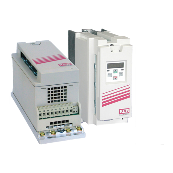
KEB COMBIVERT F5 Instruction Manual
Housing b, 0.37...2.2 kw, 230v, 0.37...4.0kw, 400v
Hide thumbs
Also See for COMBIVERT F5:
- Applications manual (378 pages) ,
- Reference manual (349 pages) ,
- Instruction manual (196 pages)

Related Manuals for KEB COMBIVERT F5


Summary of Contents for KEB COMBIVERT F5
- Page 1 COMBIVERT GB Instruction Manual Housing B 0.37...2.2 kW 230 V 0.37...4.0 kW 400 V Original manual Mat.No. Rev. 00F50EB-KB00...
-
Page 3: Table Of Contents
Table of Contents Table of Contents Preface ......................5 Information on special measures ..................5 Documentation ........................5 Validity and liability ......................6 Copyright ..........................6 1.5 Specified application ......................7 Product description ......................7 1.7 Unit identification ........................8 Installation instructions ......................9 1.8.1 Cooling systems ........................9 1.8.2 Control cabinet installation ....................10 Safety and application notes .................... - Page 4 Table of Contents Annex A ......................27 Overload characteristic .....................27 Overload protection in the lower speed range ...............27 Calculation of the motor voltage ..................28 Shut down ..........................28 A.4.1 Maintenance ........................28 A.4.2 Storage ..........................28 A.4.3 Cooling circuit ........................29 A.4.4 Fault correction ........................29 A.4.5 Disposal ..........................29 Annex B ......................
-
Page 5: Preface
Preface Preface The described hard and software are developments of the KEB Automation KG. The en- closed documents correspond to conditions valid at printing. Misprint, mistakes and technical changes reserved. Information on special measures The used pictograms have following significance:... -
Page 6: Validity And Liability
KEB Automation KG agency. Copyright The customer may use the instruction manual as well as further documents or parts from it for internal purposes. Copyrights are with KEB and remain valid in its entirety. -
Page 7: Specified Application
The used semiconductors and components of KEB Automation KG are developed and di- mensioned for the use in industrial products. If the KEB COMBIVERT F5 is used in machines, which work under exceptional conditions or if essential functions, life-supporting measures or an extraordinary safety step must be fulfilled, the necessary reliability and security must be ensured by the machine builder. -
Page 8: Unit Identification
Preface Unit identification 09 . F5 . B B - 3 Cooling A: Heat sink B: Flat rear Encoder interface 0: none Switching frequency; short time current limit; overcurrent limit 5: 4 kHz; 150 %; 180 % 9: 4 kHz; 180 %; 216 % A: 8 kHz;... -
Page 9: Installation Instructions
Installation instructions 1.8.1 Cooling systems The KEB COMBIVERT F5 is available for different cooling systems: Heat sink with cooling fan (mounted version) The standard version is delivered with heat sink and cooling fan. Special versions The dissipation of power loss must be guaranteed by the machine builder. -
Page 10: Control Cabinet Installation
1.8.2 Control cabinet installation Mounting distances Dimen- Distance in mm Distance in sions inch 1) Distance to preceding control elements in the con- trol cabinet door. Direction of the Front and side view of the coolant inlet cooling fins Coolant outlet Coolant inlet Figure 1: Control cabinet installation... -
Page 11: Safety And Application Notes
Safety and application notes Safety and application notes Safety and operating instructions for drive converter (in accordance with: Low-Voltage Directive 2006/95/EC) 4. Installation 1. General The devices must be installed and cooled according to the In operation, drive converter depending on their degree of regulations in the corresponding documentation. -
Page 12: Technical Data
The specified value is only meet in connection with a corresponding filter. Depending on the conditions and the appropriate derating higher temperatures can also be run in consultation with KEB. There is no "Safe isolation" of the control above 2000 m. -
Page 13: Technical Data Of The 230V Class
(xxF5Cxx-xxxx). This devices are not subject to export authorisation. Info Note pole pairs The technical data are for 2/4-pole standard motors. With other pole numbers the inverter must be dimensioned onto the motor rated current. Contact KEB for special or medium frequency motors. -
Page 14: Technical Data Of The 400V Class
Technical data of the 400V class Inverter size Housing size Phases Output rated power [kVA] 0.9 Max. rated motor power [kW] 0.37 0.75 Output rated current [A] 1.3 5.8 9.5 Max. short time current [A] 2.3 10.4 17 OC-tripping current [A] 2.8 12.5 21 Input rated current... -
Page 15: Dc Supply
2.4.2 Internal input circuit The COMBIVERT F5/F6 in B housing corresponds to the inverter type A1. Pay attention to the inverter type in DC interconnection and in operation at regenerative units. Inverter type for COMBIVERT F5/F6 in B housing: A1... -
Page 16: Dimensions And Weights
Dimensions and weights 2.5.1 Dimensions mounted version (representation with optional mounting kit) Weight: 2 kg Figure 3: Dimensions mounted version... -
Page 17: Dimensions Flat Rear (Representation With Optional Mounting Kit)
2.5.2 Dimensions Flat Rear (representation with optional mounting kit) 281,4 Ă 5,5 Weight: 1.8 kg Figure 4: Dimensions Flat Rear... -
Page 18: Mounted Version With/Without Operator
2.5.3 Mounted version with/without operator Figure 5: Mounted version with/without operator 2.5.4 Flat Rear mit/ohne Operator Figure 6: Flat Rear with/without operator... -
Page 19: Terminal Strips Of The Power Circuit
Terminal strips of the power circuit Caution Observe input voltage, since 230 V and 400 V class possible All terminal strips meet the requirements according to EN 60947-7-1 Info (IEC 60947-7-1) Name Function Cable cross-sections Terminals No. L1, N 1-phase mains connection L1, L2, L3 3-phase mains connection U, V, W Motor connection... -
Page 20: Accessories
Accessories 2.7.1 Filter and chokes Voltage class Inverter Filter Mains choke 50 Hz Motor choke 100 Hz size (4 % Uk) (4 % Uk) 05Z1B02-1000 – 230 V 07Z1B02-1000 – 10E5T60-0001 1-phase 09Z1B02-1000 – 10Z1B02-1000 – 05Z1B03-1000 – 10E5T60-1001 230 V 07Z1B03-1000 –... -
Page 21: Connection Power Unit
Caution Incorrect connection possible! • Absolutely pay attention to the supply voltage of the KEB COMBIVERT. A 230 V unit at 400 V mains is destroyed immediately. • Exchanging mains and motor connection leads to immediate destruction of the unit. -
Page 22: Mains Connection 3-Phase
Motor protection temperature sensor (also see 2.8.4) 2.8.1.3 DC connection T1 T2 Figure 10: DC connection Legend DC supply DC fuses Mains contactor KEB COMBIVERT F5 with DC input Motor (see also 2.8.3) Motor protection temperature sensor (also see 2.8.4) -
Page 23: Selection Of The Motor Cable
2.8.2 Selection of the motor cable The correct selection and wiring of the motor cable is very important: • lower abrasion of the motor bearings by leakage currents • improved EMC characteristics • lower symmetrical operating capacities • less losses by transient currents 2.8.3 Connection of the motor As standard the connection of the motor must be carried out in accordance with the following table:... -
Page 24: Temperature Detection T1, T2
2.8.4 Temperature detection T1, T2 In.17 Function of T1, Pn.72 Resistance Display ru.46 Error/Warn- (F6 => ru28) (dr33) < 750 Ω T1-T2 closed – 0.75…1.65 kΩ undefined – (in accord- (reset resistance) ance with 1.65…4 kΩ undefined DIN EN 60947-8) (tripping resistance) >... -
Page 25: Connection Of A Braking Resistor
2.8.5 Connection of a braking resistor Warning Very high surface temperatures Braking resistors dissipate the produced energy of the motor into heat during generatoric operation. Thus braking resistors can cause very high surface temperatures. During assem- bly pay attention to appropriate protection against contact and fire. Info Regenerative unit The use of a regenerative unit is reasonable for applications which produce a lot of regener-... -
Page 26: 2.8.5.2 Braking Resistor With Overheat Protection
2.8.5.2 Braking resistor with overheat protection This circuit offers a direct protection with defective braking transistor (GTR7). The braking resistor overheats and opens the terminals OH1 and OH2 with defective GTR7. The OH terminals open the holding circuit of the input contactor, so that the input voltage is switched off in error case. -
Page 27: Annex A
Annex A Annex A Overload characteristic Time [s] Load [%] 105 110 115 120 125 130 135 140 145 150 160 170 180 190 200 210 220 In this range the characteristic declines dependent on the overcurrent limit (see unit identification). Figure 15: Overload characteristic On exceeding a load of 105% the overload integrator starts. -
Page 28: Calculation Of The Motor Voltage
A.4.2 Storage The DC link of the KEB COMBIVERT is equipped with electrolytic capacitors. If the electrolyt- ic aluminium capacitors are stored de-energized, the internal oxide layer is removed slowly. Due to the leakage current the oxide layer is unrenewed. If the capacitor starts running with rated voltage there is a high leakage current which can destroy the capacitor. -
Page 29: Cooling Circuit
Storage period > 3 years • Input voltages as before, however double the times per year. Eventually change capac- itors. After expiration of this start-up the KEB COMBIVERT can be operated on nominal rating con- ditions or delivered to a new storage. A.4.3 Cooling circuit The cooling circuit must be completely empty if a unit shall be switched off for a longer period. -
Page 30: Annex B
B.1.2 UL Marking Acceptance according to UL is marked at KEB inverters with the adjacent logo on the type plate. To be conform according to UL for use on the North American and Canadian Market the fol- lowing additionally instructions must be observed (original text of the UL-File): •... - Page 31 Annex B • Integral solid state short circuit protection does not provide branch circuit protection. Branch circuit protection must be provided in ac- cordance with the Manufacturer Instructions, National Electrical Code and any additional local codes, or the equivalent. Branch Circuit Protection for inverters F5–B housing: Inverter Input Voltage UL248 Fuse Class CC, J or...
- Page 32 Manuals for construction and development • Application manual • Creation of a user-defined parameter menu • Programming of the digital inputs • Input fuses in accordance with UL for COMBIVERT F5 Certificates and approvals • CE declaration of conformity • UL-Yellow Card (http://www.ul.com)
-
Page 33: Annex C
Annex C Annex C Changing the response threshold of the braking transistor (not valid for control type „BASIC“) To avoid a premature switching of the brake transistor at an input rated voltage of 480 Vac, the response threshold must be controlled or adjusted according to the following graphic. FUNC. - Page 34 +39 02 3353531 • fax: +39 02 33500790 net: www.keb.de • mail: kebitalia@keb.it KEB Power Transmission Technology (Shanghai) Co.,Ltd. No. 435 Qianpu Road, Chedun Town, Songjiang District, KEB Japan Ltd. Shanghai 201611, P.R. China 15–16, 2–Chome, Takanawa Minato-ku fon: +86 21 37746688 • fax: +86 21 37746600...
Need help?
Do you have a question about the COMBIVERT F5 and is the answer not in the manual?
Questions and answers