KEB COMBIVERT F6 Instruction Manual
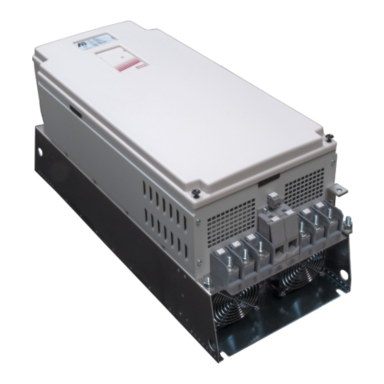
Housing u
55...90kw 230v
75...200kw 400v
Hide thumbs
Also See for COMBIVERT F6:
- Programming manual (544 pages) ,
- Reference manual (305 pages) ,
- Instructions for use manual (88 pages)

Related Manuals for KEB COMBIVERT F6


Summary of Contents for KEB COMBIVERT F6
- Page 1 COMBIVERT Instruction Manual Housing U 55…90 kW 230 V 75…200 kW 400 V Original manual Mat.No. Rev. 00F50EB-KU00...
-
Page 3: Table Of Contents
Table of content Preface ......................5 General ..........................5 Validity and liability ......................5 Copyright ..........................6 1.4 Specified application ......................6 Product description ......................6 Part code ..........................7 Transport instructions ......................8 Installation instructions ...................... 8 1.8.1 Cooling systems ........................8 1.8.2 Control cabinet installation ..................... - Page 4 Table of content Annex A ........................37 Overload characteristic ..................... 37 Overload protection in the lower speed range ............... 37 Calculation of the motor voltage ..................38 Maintenance ........................38 Storage ..........................38 A.5.1 Cooling circuit ........................39 Annex B ........................40 B.1 Certification ........................
-
Page 5: Preface
Preface Preface General The described hard- and software are developments of the KEB Automation KG. The en- closed documents correspond to conditions valid at printing. Misprint, mistakes and technical changes reserved. The instruction manual must be made available to the user. Before working with the unit the user must become familiar with it. -
Page 6: Copyright
The used semiconductors and components of KEB are developed and dimensioned for the use in industrial products. If the KEB COMBIVERT is used in machines, which work under exceptional conditions or if essential functions, life-supporting measures or an extraordinary safety step must be fulfilled, the necessary reliability and security must be ensured by the machine builder. -
Page 7: Part Code
Preface Part code 27 . F5 . A B U-9 0 0 A Cooling 0, 5, A, F Heat sink (standard) 1, B, G Flat rear 2, C, H Water-cooling system 3, D, I Convection Encoder interface 0: none Switching frequency; short time current limit; overcurrent limit 2 kHz;... -
Page 8: Transport Instructions
To avoid damage, the inverter may only be transported on suitable pallets. Installation instructions 1.8.1 Cooling systems The KEB COMBIVERT F5/F6 is available for different cooling systems: Heat sink with cooling fan (mounted version) The standard version is delivered with heat sink and cooling fan. Special versions The dissipation of power loss must be guaranteed by the machine builder. -
Page 9: Control Cabinet Installation
General 1.8.2 Control cabinet installation Mounting distances Dimen- Distance in mm Distance in sion inch 1) Distance to preceding elements in the cabinet door. Direction of the Front and side view of the coolant inlet cooling fins Coolant outlet Coolant inlet See annex C for instructions of water-cooled units. -
Page 10: Safety And Application Notes
Safety Instructions Safety and application notes Safety and application notes for drive converter (in accordance with: Low-Voltage Directive 2006/95/EC) 1. General 4. Installation In operation, drive converter depending on their degree of The installation and cooling of the appliances shall be in protection, may have live, uninsulated and possibly also accordance with the specifications in the pertinent docu- moving or rotating parts, as well as hot surfaces. -
Page 11: Technical Data
Technical Data Technical Data Operating conditions Standard Standard/ Instructions class EN 61800-2 Inverter product standard: rated specifications Definition acc. EN 61800-5-1 Inverter product standard: general safety max. 2000 m above sea level Site altitude With site altitudes over 1000 m a derating of 1 % per 100 m must be taken into consideration. -
Page 12: Technical Data Of The 230V Class
The technical data are for 2/4-pole standard motors. With other pole numbers the inverter must be dimensioned onto the motor rated current. Contact KEB for special or medium fre- quency motors. -
Page 13: Technical Data Of The 400 V Class
The technical data are for 2/4-pole standard motors. With other pole numbers the inverter must be dimensioned onto the motor rated current. Contact KEB for special or medium fre- quency motors. -
Page 14: Dc Supply
Technical Data of the 400 V Class The response threshold of the braking transistsor (Pn.69) for all controls without safe- ty technology must be adjusted at least to 770 Vdc (see annex D). 2.3.1 DC supply 2.3.2 Calculation of the DC input current The DC input current of the inverter is basically determined by the used motor. -
Page 15: Dimensions And Weights
Technical Data - Dimensions and Weights Dimensions and Weights 2.4.1 Mounted version with sub construction (default) Housing type Weight Air-cooling 800 340 300 775 Ø11 75 kg Water cooling 2-plate heat sink (special version) 800 340 275.5 300 775 Ø11 –... -
Page 16: Through-Mount Version Heat Sink With Fan (Size 24
Technical Data - Dimensions and Weights 2.4.2 Through-mount version heat sink with fan (size 24…27) 201,5 GB - 16... -
Page 17: Mounted Version Water-Cooled Heat Sink
Technical Data - Dimensions and Weights 2.4.3 Mounted version water-cooled heat sink G 1/2" DIN ISO 228-1 201,5 GB - 17... -
Page 18: Through-Mount Version Water-Cooled Heat Sink
Technical Data - Dimensions and Weights 2.4.4 Through-mount version water-cooled heat sink 203,5 Housing type Weight Water-cooled heat sink 58 kg Water-cooled heat sink with braking resistor 63 kg Primary and secondary water-cooled heat sink 83.2 – Primary and secondary water-cooled heat sink with braking resistor 98.2 –... -
Page 19: Through-Mount Version Water-Cooled Heat Sink With Stud
Technical Data - Dimensions and Weights 2.4.5 Through-mount version water-cooled heat sink with stud 203,5 Housing type B *) Weight Water-cooled heat sink 58 kg Water-cooled heat sink with braking resistor 63 kg Primary and secondary water-cooled heat sink 83.2 –... -
Page 20: Through-Mount Version Water-Cooled Heat Sink With Stud (Small Design)
Technical Data - Dimensions and Weights 2.4.6 Through-mount version water-cooled heat sink with stud (small design) U2.F4.T05-0008 G 1/2 " DIN ISO 228-1 203,5 Housing type B *) Weight Water-cooled heat sink 58 kg Water-cooled heat sink with braking resistor 63 kg *) only at plug-on terminal cover GB - 20... -
Page 21: Through-Mount Version Water-Cooled Heat Sink Without Stud (Small Design)
Technical Data - Dimensions and Weights 2.4.7 Through-mount version water-cooled heat sink without stud (small design) G 1/2 DIN ISO 228-1 203,5 Housing type B *) Weight Water-cooled heat sink 58 kg Water-cooled heat sink with braking resistor 63 kg *) only at plug-on terminal cover GB - 21... -
Page 22: Terminal Strips Of The Power Circuit
Terminals 400 V Class Terminal strips of the power circuit 2.5.1 Terminal strips for 400V units All terminal strips following the requirements of the EN 60947-7-1 (IEC 60947-7-1) Unit size 23…25 default with GTR7 Terminal in accordance with table 2.5 Name Function L1, L2, 3-phase mains connection... - Page 23 Terminals 400 V Class Unit size 26…27 28 default with GTR7 Terminal in accordance with table 2.5 Name Function L1, L2, 3-phase mains connection U, V, W Motor connection PA, PB Connection for braking resistor T1, T2 Connection for temperature sensor K1, K2 GTR7 monitoring (optional) PA PB Connection for shielding / earthing...
- Page 24 Terminals 400 V Class Unit size 26, 27 advanced special version Terminal in accordance with table 2.5 Name Function L1, L2, 3-phase mains connection U, V, W Motor connection PA, PB Connection for braking resistor K1K2 DC link voltage 420…746 V DC (400V class) Connection for braking module, +PA, –...
- Page 25 Terminals 400 V Class Housing size 23…27 DC versionSpecial ver- Terminal in accordance with table 2.5 sion without GTR Name Function DC voltage input ++, -- 420…746 V DC (400V class) U, V, W Motor connection DC link voltage 420…746 V DC (400V class) +, - Connection for braking module,...
-
Page 26: Terminal Strips For 230V Units
Terminals 400 V Class Housing size 23…27 DC version without Terminal in accordance with table 2.5 GTR7 Name Function DC voltage input ++, -- 420…746 V DC (400V class) U, V, W Motor connection DC link voltage 420…746 V DC T1 T2 (400V class) +, -... - Page 27 Terminals 230 V Class Unit size 22…24 default without GTR7 Terminal in acc. with table 2.6 Name Function L1, L2, 3-phase mains connection U, V, W Motor connection T1 T2 DC link voltage 250…370 V DC (200V class) +, - Connection for braking module, filter or DC link coupling (unsuitable for DC supply)
-
Page 28: Connection Accessories
Connection Power Unit Connection Accessories 2.6.1 Filter and chokes For further information about filters and chokes for 230V units are available upon request. Voltage class Inverter size Mains choke 50 Hz / 4 % Uk Motor choke 100 Hz / 4 % Uk 23DRB18-1741 23DRC18-8231 24DRB18-1541... -
Page 29: Connection Power Unit
Motor (see also 2.7.3) Motor protection temperature sensor (also see 2.7.4) T1 T2 Legend DC supply DC fuses Mains contactor KEB COMBIVERT F5/F6 with DC input Motor (see also 2.7.3) Motor protection temperature sensor (also see 2.7.4) GB - 29... -
Page 30: Selection Of The Motor Cable
Connection Power Unit 2.7.2 Selection of the motor cable Correct selection and wiring of the motor cable is very important: • lower abrasion of the motor bearings by leakage currents • improved EMC characteristics • lower symmetrical operating capacities • less losses by transient currents Picture Cross section of a shielded motor cable with tripartited protective earth con- 2.7.2... -
Page 31: Temperature Detection T1, T2
Connection Power Unit 2.7.4 Temperature detection T1, T2 Parameter In.17 displays in high byte the installed temperature input of the inverter. The F5/ F6 COMBIVERT is delivered as standard with switchable PTC evaluation. A switchable KTY/ PTC evaluation is optionally available. The desired function is adjusted with Pn.72 (dr33 at F6) and operates in accordance with the following table: Pn.72 Resistance... -
Page 32: 2.7.4.1 Use Of The Temperature Input In Kty Mode
Connection Power Unit Do not lay KTY or PTC cable of the motor (also shielded) together with control • cable ! • KTY or PTC cable only permissible with double shielding within the motor cable ! The error message E.dOH should never be disabled, otherwise the load shunt is no longer evaluated. -
Page 33: Connection Of A Braking Resistor
Connection Power Unit Wiring example in PTC mode Mixed sensor chain The function can be switched off with Pn.12 = “7“ (CP.28) if no evaluation of the input is desired (standard in operating mode GENERAL). Alternatively a bridge can be installed be- tween T1 and T2. -
Page 34: 2.7.5.1 Braking Resistor Without Temperature Monitoring
Connection Power Unit 2.7.5.1 Braking resistor without temperature monitoring Intrinsically safe braking resistor without temperature monitoring Only "intrinsically safe" braking resistors are permissible for operation without tem- perature monitoring. 2.7.5.2 Braking resistor with over-heat protection and GTR7 monitoring This circuit offers a direct protection with defective GTR7 (braking transistor). At defective braking transistor an integrated relay opens the terminals K1/K2 and error „E.Pu“... -
Page 35: 2.7.5.3 Braking Resistor With Over-Heat Protection Without Gtr7 Monitoring
Connection Power Unit Braking resistor with over-heat protection and GTR7 monitoring +24V GTR7-Error L1 L2 K1 K2 T1 T2 K3 Line contactor with auxiliary contacts R1 Braking resistor with temperature switch S1 Key for switch on R2 PTC or KTY84 sensor e.g. of the motor S2 Emergency stop circuit braker for switch off DR1 Mains choke with temperature switch (optional) H1 Tripping control HF1 HF filter... -
Page 36: External Fan Power Supply
Connection Power Unit Braking resistor with over-heat protection without GTR7 monitoring +24V L1 L2 L3 T1 T2 K3 Line contactor with auxiliary contacts R1 Braking resistor with temperature switch S1 Key for switch on R2 PTC/KTY84 sensor e.g. of the motor S2 Emergency stop circuit braker for switch off DR1 Mains choke with temperature switch (optional) H1 Tripping control HF1 HF filter... -
Page 37: Annex A
Annex Annex A Overload characteristic Time [s] Time [s] 105 110 115 120 125 130 135 140 145 150 160 170 180 190 200 210 220 105 110 115 120 125 130 135 140 145 150 Load [%] Load [%] Characteristic 1 Characteristic 2 The characteristic declines device-dependently in this range... -
Page 38: Calculation Of The Motor Voltage
Storage The DC link of the KEB COMBIVERT is equipped with electrolytic capacitors. If the electrolyt- ic aluminium capacitors are stored de-energized, the internal oxide layer is removed slowly. Due to the leakage current the oxide layer is unrenewed. If the capacitor starts running with rated voltage there is a high leakage current which can destroy the capacitor. -
Page 39: Cooling Circuit
Storage period > 3 years • Input voltages as before, however double the times per year. Eventually change capac- itors. After expiration of this start-up the KEB COMBIVERT can be operated on nominal rating con- ditions or delivered to a new storage. A.5.1 Cooling circuit The cooling circuit must be completely empty if a unit shall be switched off for a longer period. -
Page 40: Annex B
B.1.2 UL Marking Acceptance according to UL is marked at KEB inverters with the adjacent logo on the type plate. To be conform according to UL for the use on the North American and Canadian Market the following instructions must be observed (original text of the UL): •... - Page 41 Amperes, 480 Volts Maximum when Protected by Class ____ Fuses, rated ___ Amperes as specified in table I”: or when Protected by A Circuit Breaker Having an Interrupting rating Not Less than 100 kA rms Symmetrical Amperes, 480V maximum, rated ___ Amperes as specified in table I”: Table I Branch Circuit Protection for KEB inverters F5/F6–U housing: a) UL 248 Fuses; Class RK5, J or L as specified below Inverter Input...
-
Page 42: Annex C
This has positive effects on lifetime-relevant components such as fan and DC link circuit capacitors and power modules (IGBT). Also the temperature dependent switching losses are positively effected. The use of water-cooled KEB COMBIVERT frequen- cy inverters is offered in the drive technology, because there are process-caused coolants available with some applications. -
Page 43: Requirements On The Coolant
Annex Table 1.5.2 Electro-chemical voltage series / standard potentials against hydrogen Material generated Ion Standard po- Material generated Ion Standard po- tential tential Aluminium -1.67 V Copper 0.34 V Manganese -1.05 V Carbon 0.74 V Zinc -0.76 V Silver 0.80 V Chrome -0.71 V Platinum... -
Page 44: Connection To The Cooling System
• The valves must be installed in the flow pipe to keep the return flow pipe pressure free. • Pay attention to flux direction and check tightness ! • The cooling flow must always be started before starting the KEB COMBIVERT. The connection to the cooling system can occur as closed or open cooling circuit. The con- nection to a closed cycle cooling circuit is recommended, because the danger of contamina- tion of coolant is very small. - Page 45 Annex Supply of temper coolant This is possible by using heatings in the cooling circuit for the control of the coolant temper- ature. The following dew point table is available for this: Coolant inlet temperature [°C] is depending on ambient temperature and air humidity Air humidity [%] Surrounding temperature [°C]...
-
Page 46: C.1.6 Coolant Heating Depending On Power Loss And Flow Rate With Water
Annex C.1.6 Coolant heating depending on power loss and flow rate with water ΔT [K] 5 l/min 10 l/min 20 l/min 30 l/min 40 l/min 50 l/min 100 l/min Pv [kW] C.1.7 Typically fall of pressure depending on the rate of flow l/min GB - 46... -
Page 47: Annex D
Annex Annex D Changing the response threshold of the braking transistor To avoid a premature switching of the brake transistor at an input rated voltage of 480 Vac, the response threshold must be controlled or adjusted according to the following graphic. FUNC. - Page 48 KEB Italia S.r.l. fon: +32 5443 7860 • fax: +32 5443 7898 Via Newton, 2 • 20019 Settimo Milanese (Milano) mail: vb.belgien@keb.de fon: +39 02 3353531 • fax: +39 02 33500790 net: www.keb.de • mail: kebitalia@keb.it KEB Power Transmission Technology (Shanghai) Co.,Ltd. No. 435 Qianpu Road, Chedun Town, Songjiang District, KEB Japan Ltd. Shanghai 201611, P.R. China 15–16, 2–Chome, Takanawa Minato-ku fon: +86 21 37746688 • fax: +86 21 37746600 Tokyo 108-0074 net: www.keb.de • mail: info@keb.cn fon: +81 33 445-8515 • fax: +81 33 445-8215...
Need help?
Do you have a question about the COMBIVERT F6 and is the answer not in the manual?
Questions and answers
We have error nuber 17 on the pannel