KEB COMBIVERT F6 Instructions For Use Manual
Application drive; installation f6 a-control
Hide thumbs
Also See for COMBIVERT F6:
- Programming manual (544 pages) ,
- Reference manual (305 pages) ,
- Instructions for use manual (88 pages)

Subscribe to Our Youtube Channel
Related Manuals for KEB COMBIVERT F6


Summary of Contents for KEB COMBIVERT F6
- Page 1 COMBIVERT F6 INSTRUCTIONS FOR USE | INSTALLATION F6 A-CONTROL Translation of the original manual Dokument 20118593 EN 02...
-
Page 3: Preface
PReFACe Preface The described hard- and software are developments of the KEB Automation KG. The enclosed documents correspond to conditions valid at printing. Misprint, mistakes and technical changes reserved. Signal words and symbols Certain operations can cause hazards during the installation, operation or thereafter. -
Page 4: Laws And Guidelines
Copyright The customer may use the instruction manual as well as further documents or parts from it for internal purposes. Copyrights are with KEB Automation KG and remain valid in its entirety. Other wordmarks or/and logos are trademarks (™) or registered trademarks (®) of their... -
Page 5: Table Of Contents
TAbLe OF CONTeNTS Table of Contents Preface ..............................3 Signal words and symbols ......................3 More symbols ..........................3 Laws and guidelines ........................4 Warranty ............................4 Support ............................4 Copyright ............................4 Table of Contents ........................... 5 List of Figures ............................7 List of Tables ............................8 Glossary .............................. - Page 6 TAbLe OF CONTeNTS 2.4.4 Connection and specification of the relay output..............23 2.4.5 Specification and connection of the analog inputs ............. 24 2.4.6 Specification and connection of the analog output ............. 25 2.4.7 Voltage input for supply of the control board and the brake ..........25 2.5 Terminal block X2b ........................26 2.6 Diagnosis/visualisation ......................... 27 2.6.1 Assignment of the interface X4A ..................27 2.6.2 Data cable RS232 PC inverter ...................
-
Page 7: List Of Figures
LIST OF FIGUReS List of Figures Figure 1: Overview control board ....................16 Figure 2: Assembly of the control cable ..................20 Figure 3: Assignment of the terminal strip X2A ................21 Figure 4: Connection of the digital inputs at X2A ................22 Figure 5: Examples for the connection of the digital outputs at X2A .......... -
Page 8: List Of Tables
LIST OF TAbLeS List of Tables Table 1: LEDs at power on ......................18 Table 2: LED function VCC ......................18 Table 3: LED function FB-ST ......................18 Table 4: LED function DEV-ST ...................... 19 Table 5: LED function OPT ......................19 Table 6: Wire-end ferrules and stripping length ................ -
Page 9: Glossary
(DIN 5008) Sea level Fieldbus system Overcurrent COMBIVERT KEB drive converters Overheat COMBIVIS KEB start-up and parameterizing Overload software OSSD Output signal swithching device; - an DC current or voltage output signal that is checked in regu- lar intervals on its shutdown. (safety... - Page 10 GLOSSARy The security integrity level is a measure for quantifying the risk reduction. Term used in the safety technology (EN 61508 -1...7). Safety function „Safe stop 1“ in ac- cordance with IEC 61800-5-2 Synchronous serial interface for encoder Safety function „Safe Torque Off“ in accordance with IEC 61800-5-2 Incremental signal with an output voltage up to 5 V...
-
Page 11: Standards For Controls With / Without Safety Technology
STANDARDS FOR CONTROLS WITh / WIThOUT SAFeTy TeChNOLOGy Standards for controls with / without safety technology DGUV regulation 3 Electrical installations and equipment DIN 46228-1 Wire-end ferrules; Tube without plastic sleeve DIN 46228-4 Wire-end ferrules; Tube with plastic sleeve DIN IEC 60364-5-54 Low-voltage electrical installations - Part 5-54: Selection and erection of electrical equipment - Earthing arrangements, protective conductors and protec- tive bonding conductors (IEC 64/1610/CD) EN 60204-1... - Page 12 STANDARDS FOR CONTROLS WITh / WIThOUT SAFeTy TeChNOLOGy...
-
Page 13: Basic Safety Instructions
DGUV regulation 1.2 Validity of this manual This manual describes the control part of the COMBIVERT F6 control A. The manual • contains only supplementary safety instructions. • is only valid in connection with the power unit manual of COMBIVERT F6. -
Page 14: Electrical Connection
bASIC SAFeTy INSTRUCTIONS 1.3 electrical connection DANGeR Voltage at the terminals and in the device ! Danger to life due to electric shock ! ► For any work on the unit switch off the supply voltage and secure it against switching on. ►... -
Page 15: Control
DeSCRIPTION OF The CONTROL 2 Control 2.1 Description of the control The control board provides the following functions: • Digital and analog inputs and outputs • Potential-free relay output • CAN fieldbus interface • Serial diagnostic interface for connection to a PC •... -
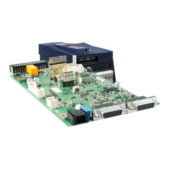
Page 16: Overview Of The Connection And Control Elements
OVeRVIeW OF The CONNeCTION AND CONTROL eLeMeNTS 2.2 Overview of the connection and control elements Temperature monitoring, brake control Control terminal block for digital inputs/outputs; 24V supply; relay output; analog inputs and outputs; CAN bus Safety modul (option) Encoder interface channel A FS ST Encoder interface channel B Diagnostic interface with RS232/485 interface according to DIN 66019II protocol /operator slot... -
Page 17: Temperature Monitoring And Brake Control (X1C)
OVeRVIeW OF The CONNeCTION AND CONTROL eLeMeNTS 2.2.1 Temperature monitoring and brake control (X1C) The terminal block X1C provides an output for the control of a 24V motor brake and an input for temperature monitoring. It is designed as 6 pole plug-in terminal block with spring cage connection. -
Page 18: Status Leds
OVeRVIeW OF The CONNeCTION AND CONTROL eLeMeNTS 2.2.7 Status LeDs 2.2.7.1 Boot display Before the LEDs start their normal function, they signal the boot procedure after switch- ing on: LEDs Status Note Device off booting control is supplied by 24 V. FPGA booted FPGA has been booted error-free (approx. -
Page 19: Dev St - Led
CONNeCTION OF The CONTROL 2.2.7.4 DEV ST - LED DEV ST LED colour Description Device off or booting Error yellow no error, DC link not loaded green no error, ready for operation flashing green no error, is used for identification of the unit (fb32) Table 4: LED function DEV-ST 2.2.7.5 OPT - LED LED colour Description... -
Page 20: Assembly Of The Wires To Push In Terminals
CONNeCTION OF The CONTROL 2.3.1 Assembly of the wires to PUSh IN terminals Attention Malfunctions caused by loose cable connections and to short wire- end ferrules! ► Use wire-end ferrules according to table “Wire-end ferrules and strip- ping length”. ► Strip cable according to table “Wire-end ferrules and stripping length”. -
Page 21: Assignment Of The Terminal Strip X2A
ASSIGNMeNT OF The TeRMINAL STRIP X2A 2.4 Assignment of the terminal strip X2A Name Description DI1 / AN3 Digital input 1 / analog input 3 (switchable via software) Digital input 2 Digital input 3 Digital input 4 Digital input 5 Digital input 6 Digital input 7 Digital input 8... -
Page 22: Voltage Outputs Of The Control Terminal Block
ASSIGNMeNT OF The TeRMINAL STRIP X2A 2.4.1 Voltage outputs of the control terminal block Name 24Vout Function Voltage output (SELV) for input control minimum P24V_IN - 3 V Output voltage maximum P24V_IN 100 mA for all 24Vout outputs together permissible total current (short-circuit proof) Table 7: Voltage output of the control... -
Page 23: Connection And Specification Of The Digital Outputs
ASSIGNMeNT OF The TeRMINAL STRIP X2A 2.4.3 Connection and specification of the digital outputs Name DO1…DO2 Number Type 24 V high-side switch Classification in accordance with DIN EN 61131-2 minimum P24V_IN - 3 V Output voltage maximum P24V_IN permissible output current 100 mA per output (short-circuit proof) only ohmic load;... -
Page 24: Specification And Connection Of The Analog Inputs
ASSIGNMeNT OF The TeRMINAL STRIP X2A 14 16 13 15 Figure 6: Example for the connection of the relay output to X2A 2.4.5 Specification and connection of the analog inputs Input type Non-isolated differential input Analog input 1 X2A.17 (AN1-), X2A.18 (AN1+) Analog input 2 X2A.19 (AN2-), X2A.20 (AN2+) Input values... -
Page 25: Specification And Connection Of The Analog Output
Imax=5mA Figure 8: Example for the connection of the analog output to X2A 2.4.7 Voltage input for supply of the control board and the brake The COMBIVERT F6 is supplied via terminals X2B.27 and X2B.28. Name Notes Reference potential for X2A.27... -
Page 26: Terminal Block X2B
TeRMINAL bLOCk X2b 2.5 Terminal block X2b The terminal block X2B based on the installed safety module. The 6th digit of the mate- rial number defines the installed safety module: Material number Safety module Type 1, STO, SBC reserved xxF6xyx-xxxx Type 3, STO, SBC, SS1, SS2, SEL, SLI, SLP, SOS, SLA, SDI, SLS, SSM, SMS, SAR, SSR and Safe over EtherCAT Table 14:... -
Page 27: Diagnosis/Visualisation
ENCODER INTERFACE 2.6 Diagnosis/visualisation The integrated serial interface provides the following functions: • Parameterization of the unit with the KEB software COMBIVIS • Connection of a control operator • DIN66019II is used as communication protocol. Interface Specification RS485 Common-mode voltage range 0…12 V... -
Page 28: Data Cable Rs232 Pc Inverter
ENCODER INTERFACE 2.6.2 Data cable RS232 PC inverter 0058025-001D Figure 11: Serial cable for the connection to a PC 2.6.3 USb-serial converter The USB-serial converter is used for the connection of drive converters, operators or IPC controls with DIN66019 interface or HSP5 interface at the USB port of PCs. The USB-serial converter is internal electrically isolated. -
Page 29: Fieldbus Interfaces
FIeLDbUS INTeRFACeS 2.7 Fieldbus interfaces The 9th digit of the material number displays if, in addition to the CAN bus, a real-time Ethernet bus module (RTE) is installed. Material number Multi fieldbus module without xxF6xxx-xyxx with The active fieldbus interface is defined with fb68. The meaning of the light pattern of the status LED "NET ST" changes accordingly. Instructions for use for the real time ethernet moduel: ma_dr_rte-inst-20148981_en.pdf 2.7.1 CAN... -
Page 30: Blink Code Net St - Led In Can Mode
FIeLDbUS INTeRFACeS 2.7.1.2 Blink code NET ST - LED in CAN mode The NET ST - LED is a combination of RUN and ERROR LED according to IG- CO_303_3v010400000. Blink code NET ST - LED (red/green combination) Status Blink code Description Pre-Op Device in state PRE-OPERATIONAL... -
Page 31: Encoder Interfaces
2.8 encoder interfaces The multi encoder interface is configured in dual-channel technique. Channel A supports the following encoder types: • Incremental encoder (RS485) input with or without zero signal • Resolver • EnDat (digital or with 1Vss incremental signals) • BISS (digital) • Hiperface • SinCos with or without zero signal; with or without absolute position (SSI or analog 1 Vpp) • Table 18: Supported encoders on channel A Channel B supports the following encoder types: •... -
Page 32: Input Signals
2.8.2 Input signals 360° mechanically / increments per revolu- tion typically 1Vpp Cos+ - Cos- typically 1Vpp Sin+ - Sin- 360° mechanically = 360° electronically Sin_abs+ - Sin_abs- typically 1Vpp Cos_abs+ - Cos_abs- typically 1Vpp N+ - N- 0.2…1.2Vpp digital position of for example Endat or Hiperface 0°... -
Page 33: Table 20: Assignment Of X3A/X3B Depending On The Adjusted Encoder Interface
(front view encoder connector) X3A / X3B: D-Sub 26-pole (HD), triple row Plug-in connector-socket Counterpart: D-Sub 26-pole (HD), triple row, Plug-in connector with fixing bolts UNC 4.40 Encoder Channel A / B A / B COS+ COS+ COS+ A+ (out) COS- COS- COS- A-(out) SIN+ SIN+ SIN+... - Page 34 2.8.3 Description of the encoder interfaces Signals only channel A: Input for two sine-wave, shifted by 90° differential signals with U =1 V, maxi- mum 200 kHz. single-ended (e.g. Cos+ against GND): Constant component 2.5 V ±0.5 V differential (e.g. Cos+ against Cos-): A+/-, Constant component 0 V ±0.1 V 1, 2,...
- Page 35 Signals Output supply voltage for encoder: 8, 9 5,25 V 5.25 V +5 %/ -10 % max. 500 mA total (250 mA per channel) Output supply voltage for encoder: =24 V max. 500 mA total (250 mA per channel) 24 V •...
-
Page 36: Brake Control And Temperature Detection
2.9 brake control and temperature detection Name Notes Brake control / output + Brake control / output - reserved reserved Temperature detection / input+ Temperature detection / input- Figure 15: Assignment of the terminal block X1C 2.9.1 Specification and connection of the brake control Name BR+ (X1C.1); BR- (X1C.2) Function... -
Page 37: Table 23: Specification Of The Temperature Input
► Cables of the motor temperature sensor inside the motor cable only permissible with double shielding ! A switchable KTY84/PTC evaluation is implemented in the KEB COMBIVERT. The de- sired operating mode can be adjusted by software (dr33). Operating mode... -
Page 38: Operation Without Temperature Detection
2.9.3 Operation without temperature detection Use of the COMBIVERT without evaluation of the temperature input: • Deactivate the evaluation (pn33 =7) • Install bridge between terminal X1C.5 and X1C.6 (dr33=1) 2.9.4 Connection of a kTy sensor Attention No protection of the motor winding in case of wrong connection. ►... -
Page 39: Figure 18: Connection Examples Of Different Temperature Sensors
X1C.5 Thermal contact (NC contact) X1C.6 X1C.5 Temperature sensor (PTC) or PT1000 X1C.6 X1C.5 mixed sensor chain X1C.6 Figure 18: Connection examples of different temperature sensors... -
Page 40: Change History
ChANGe hISTORy 3 Change history Version Date Description 2016-10 Pre-serie 2017-02 Series version 2017-07 Insert connector sets; brake control updated... - Page 41 Tel: +55 16 31161294 E-Mail: roberto.arias@keb.de Room 1709, 415 Missy 2000 725 Su Seo Dong Gangnam Gu 135- 757 Seoul Republic of Korea Tel: +82 2 6253 6771 Fax: +82 2 6253 6770 E-Mail: vb.korea@keb.de Société Française KEB SASU France Z.I.
Need help?
Do you have a question about the COMBIVERT F6 and is the answer not in the manual?
Questions and answers