Sign In
Upload
Manuals
Brands
KEB Manuals
Inverter
COMBIVERT F4-F
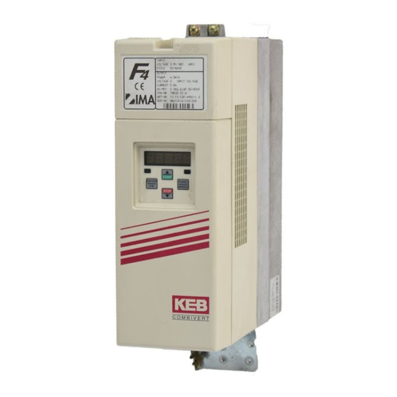
KEB COMBIVERT F4-F Frequency Inverter Manuals
Manuals and User Guides for KEB COMBIVERT F4-F Frequency Inverter. We have
4
KEB COMBIVERT F4-F Frequency Inverter manuals available for free PDF download: Applications Manual, Instruction Manual, Quick Reference
KEB COMBIVERT F4-F Applications Manual (300 pages)
Brand:
KEB
| Category:
Inverter
| Size: 6 MB
Table of Contents
General Introduction
3
Introduction
2
Table of Contents
3
Summary
5
Table of Contents
8
CP-Parameter...................................................................................... 4
13
Features of KEB COMBIVERT F4-F ................................... 2
17
Fundamentals
31
Parameters, Parameter Groups, Parameter Sets ................ 4
31
Operation
33
ENTER-Parameter
34
Parameter
34
Selection of a Parameter
34
Parameter Sets
35
Parameters
35
Resetting of Error Messages
35
Resetting of Peak Values
35
Signals
35
Drive-Mode
67
Adjustment Possibilities
67
Display and Keyboard
67
Setpoint Display /Setpoint Input
67
Rotation Setting
68
Start / Stop / Run
68
Leaving the Drive-Mode
69
Parameter
73
Parameter Groups
73
Parameterlisting F4-F
75
Functional Description
83
Operating and Unit Datas
83
Summary of Ru-Parameter
83
Summary of In-Parameter
83
Explanation to Parameter Description
84
Description of Ru-Parameter
85
Description of In-Parameter
96
Fucntional Description
101
Analog In- and Outputs
102
Brief Description
103
Analog Inputs
103
Interference Suppressor Filter Analog Inputs (An.1)
106
Gain of Input Characteristic (An.3
106
Analog Inputs
106
Gain of Input Characteristic
106
Zero Point Hysteresis of Analog Inputs (An.2 / An.8)
109
Analog Outputs
110
Gain of Output Characteristic (An.15/16, An.19/20)
111
Gain of Output Characteristic
111
Used Parameters
114
Table of Contents
115
Digital In- and Outputs
116
Brief Description Digital Inputs
117
Input Signals PNP / NPN (DI.1)
117
Input Signals
117
Terminal Status
117
Digital Filter
117
Terminal Status (Ru.14)
118
Digital Filter (DI.0)
119
Inverting of Inputs (DI.2)
119
Inverting of Inputs
119
Strobe-Dependent Inputs (DI.17
120
Strobe-Dependent Inputs
120
Function Assignment (DI.3
121
Function Assignment
121
Input Status
121
Input Status (Ru.16)
122
Brief Description - Digital Outputs
123
Output Signals
124
Switching Conditions (Do.1
124
Switching Conditions
124
Output Filter Unit (Do.26
126
Selection of Switching Conditions (Do.9
128
Logic Operation of Switching Conditions (Do.25)
128
Inverting of Switching
128
Selection of Switching
128
Logic Operation of Switching
128
Inverting of Outputs (Do.0)
129
Output Terminal Status (Ru.15)
129
Aux-Function, Setpoint and Rotation Selection 6
133
AUX-Function, Setpoint and Rotation Selection .................. 6
133
Set Value and Ramp Adjustment
134
Brief Description
135
AUX-Function, Setpoint and Rotation Selection
136
Setpoint Limits
139
Setpoint Calculation
140
Ramp Generator
142
Used Parameters
145
Modulation Rate (Ds.12) and Overmodulation (Ds.14) 6
147
Modulation Rate (Ds.12) and Overmodulation (Ds.14) ....... 6
147
Motor Data and Controller Adjustment
148
Motor Name Plate
149
Motor Data from Name Plate (Dr.0
149
Motor Data from Name Plate
149
Motor Adaption (Fr.10)
150
Controller Activation (CS.23)
151
U/F-Characteristic
152
Corner Speed / Field Weakening (Dr.19)
152
Boost (Ds.11)
152
Output Voltage Stabilization (Ds.10)
152
Field Weakening (Dr.19)
152
Output Voltage Stabilization
152
Modulation Rate (Ds.12) and Overmodulation (Ds.14)
154
Operating Frequency (Ds.13)
154
Controller Structure
155
Current Control (Torque Control)
155
Current Control
155
Speed Control
156
Torque Limitation
157
Flux Lowering Calculation
158
Flux Control/Max. Voltage Control
158
Motor Parameter Adaption
159
Torque Control
161
Used Parameters
163
Automatic Restart and Speed Search 6
165
Automatic Restart and Speed Search ................................. 6
165
Keep on Running Functions
166
Thermal Motor Protection
167
Thermal Inverter Protection
167
External Error Control Procedure
168
Procedure
168
Automatic Restart and Speed Search
169
Used Parameters
170
Non-Programmable Parameters .......................................... 6
171
Parameter Sets
172
Non-Programmable Parameters
173
Copying of Parameter Sets (Fr.0, Fr.1, Fr.9)
173
Selection of Parameter Sets
174
Locking of Parameter Sets
176
Parameter Set on and off Delay (Fr.5, Fr.6)
177
Used Parameters
177
Special Functions
180
Brake Control
181
Adjustment Assistant
185
AUX-Function (An.13)
187
Motorpotentiometer Function
189
Power-Off Function
191
Temperature Control
192
Table of Contents
193
Encoder Interface
195
Designs
195
Encoder Interface Channel 1 (X4)
196
Encoder Interface Channel
196
Encoder Interface Channel 2 (X5)
197
Selection of Encoder
199
Basic Setting
201
Power Supply of Encoder
202
Used Parameters
202
Section 10
203
Connection Accessories for Master- Slave Operation ....... 6
203
Synchronous Control
205
Activating Synchronous Control
205
KP Synchronous Control (Sn.1)
205
Gear Ratio Master/Slave (Sn.2)
205
Angular Correction (Sn.5
205
KP Synchronous Control
205
Gear Ratio Master/Slave
205
Angular Correction
205
Resetting of Angular Difference
206
Reference Point Approach
206
Reference Point Approach Examples
207
Examples
207
Connection Accessories for Master- Slave Operation
210
Connection Accessories for Master-Slave Operation
210
Used Parameters
210
Section 11
211
Adjustment/Display Mode of Position Values (Pc.1) .......... 6
211
Positioning Module
212
Activating Positioning Module (Pc.0, Pd.0)
213
Positioning
213
Adjustment/Display Mode of Position Values (Pc.1)
214
Setpoint/Actual Position and Position Setting (Pd.8
214
Position Setting in Revolutions (Pd.9, Pd.10)
215
Position Setting in Increments (Pd.8
216
Software Limit Switch (Pc.4
216
Relative/Absolute Positioning (Pd.11)
218
Target Window (Pd.12)
218
Cancel Positioning
218
Selection of Endocer Input for the Position Feedback (Pc.16)
218
Position Feedback (Pc.16)
218
Profile of Speed Precontrol (Pd.3, Pd.5
219
Optimizing Position Controller (Pd.2)
220
Teach - Function (Pd.1)
220
Teach-Function (Pd.1)
220
Reference Point Approach
221
Reference Point Approach Examples
222
Adjustment of Position Controller and Drive Profile
225
Controller and Drive Profile
225
Check List
227
Programming Examples
228
Used Parameters
235
CP-Parameter Definition
238
Survey
239
Assignment of CP-Parameter
240
Start Parameter (Ud.2, Ud.3)
240
Example
241
Used Parameters
241
Preparatory Measures
247
After Unpacking the Goods
247
Installation and Connection
247
Checklist Prior to Start-Up
248
Start-Up (Controlled)
251
Start-Up (Closed-Loop)
252
Start-Up
247
Special Operation
254
Error Assistance
257
Troubleshooting
257
General
257
Error Messages and Their Cause
257
Project Planning
263
General Design
263
Control Cabinet Design Calculation
263
Design of Braking Resistors
264
Networks
271
Network Components
271
Available Hardware
271
RS232-Cable Pc/Inverter
271
Interface- and Bus-Operator
272
Optical Fibre BUS
273
Interbus Loop-Operator
277
Hardware
278
Operation
279
Parameter
280
Bus-/DRIVECOM-Parameter
281
Adjustment of Inverter Address (Ud.6)
281
Baud Rate (Ud.7)
281
Watchdog-Time (Ud.8)
281
Functions
281
Used Parameter
282
Start-Up
283
Applications
284
Error Assistance
285
Search and Find
286
Index
287
Applications
287
Annex
288
Networks
290
Term Definition
293
KEB- Worldwide
295
Notes
297
Advertisement
KEB COMBIVERT F4-F Instruction Manual (66 pages)
Brand:
KEB
| Category:
Lifting Systems
| Size: 1 MB
Table of Contents
Table of Contents
3
1 Operating Specifications
4
Application
4
Protective Separation
4
Inteference Protection of Electric Systems
4
Inteference Protection of Frequency Inverters
4
2 Summary
5
3 Inputs/Outputs
6
Terminal X2 - Control Terminals
6
Terminal X3 - I/O-Expander
7
Function of the Digital Inputs
8
Function of the Digital Outputs / Relay Outputs
10
4 Drive Curves
12
Activation of the Main Drive
12
Activation of the Door Drive
14
Control of a 2Nd Motor for the Door Drive
14
U/F-Curve Door Drive
14
ACC and DEC Ramps
14
Set Speed Door Drive
14
Drive Curve Door Drive
15
5 Change in the Operating Frequency
16
Temperature Dependent Changes in the Operating Frequency
16
Digital Output X3.14 Operating Frequency Warning
16
6 Connection
17
Wiring Diagram: Control Terminal X2 and I/O-Expander X3
17
Connection X4 - Incremental Encoder
18
Connection Incremental Encoder
19
Connection SIN/COS Encoder
19
Connection Resolver
20
Connection X5 - Incremental Encoder Emulation
20
7 Operation
21
Digital / Interface Operator
21
Parameter Identification
22
Parameter Selection
22
Changing Parameter Values
23
Parameter Structure
23
Storing Parameter Values
24
Error Messages
24
8 Parameter Description
25
LF-Parameters
25
Ru-Parameters
50
In-Parameters
54
9 Start-Up Assistance
57
Initial Start-Up
57
Adjustment Instructions for Conventional Lift Motors
59
10 Supplement
60
New Functions from Version 1.4
60
Control Instructions
60
Parameter List
61
Customer Application Parameter
64
KEB COMBIVERT F4-F Instruction Manual (46 pages)
Control Circuit
Brand:
KEB
| Category:
DC Drives
| Size: 1 MB
Table of Contents
Table of Contents
3
1 Operating Specifications
4
Application
5
Moving or Rotating Parts
5
High Operating Temperatures
5
Connection Instructions
5
Operating Instructions
6
Interference Protection of Electric Systems
7
Interference Protection of the Frequency Inverter
7
2 Connection
8
Summary
8
Terminal X2
9
Parameter Interface
11
Connection X4 Incremental Encoder
12
Connection X5 Option
13
3 Operation of the Unit
14
Keyboard
14
Parameter Summary
15
4 Parameter Description
16
5 Drive-Mode
36
Adjustment Possibilities
36
Condition
36
Display and Keyboard
36
Setvalue Display / Setvalue Presetting
36
Rotation Presetting
37
Start / Stop / RUN
37
6 Error Diagnosis
38
7 Startup
40
8 Short Manual
42
9 Password
43
Advertisement
KEB COMBIVERT F4-F Quick Reference (30 pages)
Brand:
KEB
| Category:
Lifting Systems
| Size: 0 MB
Table of Contents
Table of Contents
3
1 Inputs/Outputs
4
Terminal X2 Control Terminals (Units > G-Housing)
4
Terminal X3 I/O-Expander (Units > G-Housing)
5
Terminal X2 Control Terminals (D- and E-Housing)
6
2 Connection
7
Example Connection Diagram for Lift Inverters > G-Housing
7
Example Connection Diagram for Lift Inverters in D- and E-Housing
8
Connection X4
9
Connection Incremental Encoder
9
Connection SIN/COS Encoder
9
Connection Resolver
9
Connection Hiperface Encoder
10
Connection UVW Encoder
10
Connection X5 - Incremental Encoder Emulation
10
3 Start-Up Instructions
11
Commissioning of an Asychronous Machine with Gearbox
11
Commissioning of a Gearless Permanent Magnet Machine
13
Commissioning of a Gearless Asychronous Machine
16
Commissioning of a Permanent Magnet Machine with Gearbox
18
4 Operating Parameter
20
5 Parameter Lists
24
LF-Parameter
24
Dr-Parameter
26
EC-Parameter
27
An-Parameter
27
Ru-Parameter
28
In-Parameter
28
Advertisement
Related Products
KEB COMBIVERT F6
KEB COMBIVERT F4-S Series
KEB COMBIVERT F5-B Series
KEB COMBIVERT F5-G Series
KEB COMBIVERT F5-S Series
KEB COMBIVERT F5-M Series
KEB COMBIVERT F3
KEB COMBIVERT G6M
KEB COMBIVERT P6
KEB COMBIVERT 14F5 Series
KEB Categories
DC Drives
Controller
Inverter
Control Unit
Industrial Equipment
More KEB Manuals
Login
Sign In
OR
Sign in with Facebook
Sign in with Google
Upload manual
Upload from disk
Upload from URL