KEB COMBIVERT F6 Instructions For Use Manual
Hide thumbs
Also See for COMBIVERT F6:
- Programming manual (544 pages) ,
- Reference manual (305 pages) ,
- Instructions for use manual (88 pages)

Subscribe to Our Youtube Channel
Related Manuals for KEB COMBIVERT F6


Summary of Contents for KEB COMBIVERT F6
- Page 1 COMBIVERT F6 INSTRUCTIONS FOR USE | INSTALLATION F6 OPERATOR Translation of the original manual Document 20106497 EN 05...
-
Page 3: Preface
PREFAcE Preface The described hard- and software are developments of the KEB Automation KG. The enclosed documents correspond to conditions valid at printing. Misprint, mistakes and technical changes reserved. Signal words and symbols Certain operations can cause hazards during the installation, operation or thereafter. -
Page 4: Laws And Guidelines
If applicable, the license terms of this software are contained in the instructions for use. The instructions for use are already available to you, can be downloaded free of charge from the KEB website or can be requested from the respec- tive KEB contact person. -
Page 5: Table Of Contents
TAbLE OF cONTENTS Table of contents Preface ..............................3 Signal words and symbols ......................3 More symbols ..........................3 Laws and guidelines ........................4 Warranty and liability ........................4 Support ............................4 Copyright ............................4 Table of contents ........................... 5 List of Figures ............................7 List of Tables ............................ - Page 6 TAbLE OF cONTENTS 6.2.1 Switching on ........................19 6.2.2 Required files ........................19 6.3 Non-changeable parameters ......................20 6.4 changeable parameters ........................ 21 6.4.1 Changing with „Up“ and „Down“ ..................21 6.4.1 Selection of subindices ....................... 22 6.4.2 Numeric input ........................23 6.5 Abbreviations in the function toolbar ..................23 6.6 Inverter parameter .........................
-
Page 7: List Of Figures
LIST OF FIGURES List of Figures Figure 1: Description of the operator....................12 Figure 2: Control card block incl. operator (front panel) ..............13 Figure 3: Sub-D 9-pole ........................14 Figure 4: Ethernet interface......................15 Figure 5: USB interface ........................15 Figure 6: Remove the blind cover .................... -
Page 8: Basic Safety Instructions
Knowledge of national safety regulations. 1.2 Validity of this manual This manual describes the operator of the COMBIVERT F6. The manual • contains only supplementary safety instructions. • is only valid in connection with the power unit manual of COMBIVERT F6. -
Page 9: Electrical Connection
bASIc SAFETy INSTRUcTIONS 1.3 Electrical connection DANGER Voltage at the terminals and in the device ! Danger to life due to electric shock ! ► For any work on the unit switch off the supply voltage and secure it against switching on. ► Wait until the drive has stopped in order, that perhaps regenerative energy can be generated. -
Page 10: Product Description
Technical data and information for connection conditions shall be taken from the type plate and from the instruction manual and must be strictly observed. The used semiconductors and components of the KEB Automation KG are developed and dimensioned for the use in industrial products. -
Page 11: Residual Risks
PRODUcT DEScRIPTION 2.1.1 Residual risks Despite intended use, the drive converter can reach unexpected operating conditions in case of error, with wrong parameterization, by faulty connection or non-professional interventions and repairs. This can be: • wrong direction of rotation • motor speed too high •... -
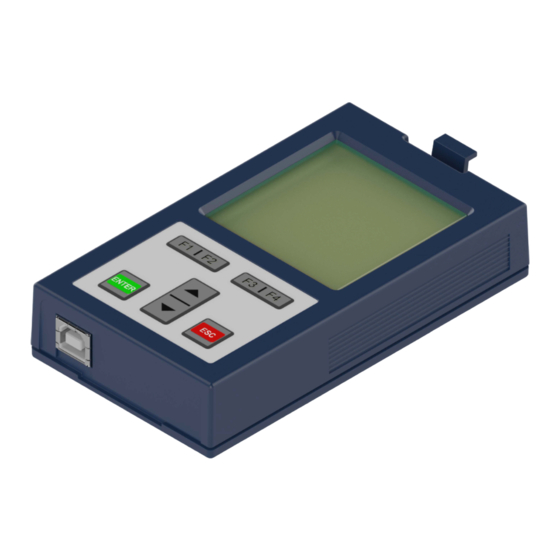
Page 12: Description Of The Operator
DEScRIPTION OF THE OPERATOR 3 Description of the Operator ① Front view Rear view ④ ② ⑤ ③ ⑥ ⑦ ⑧ bottom view Legend ① ⑤ Locking lever Nameplate ② ⑥ LC display 160 x 160 pixel, 32 levels of grey Version without interface ③... -
Page 13: Control Card Block Incl. Operator
Control card block incl. operator (front panel) 3.2 Operating conditions The description of the operating conditions can be found in the instructions for use of the used COMBIVERT F6 drive converter. NOTICE Avoidance of faulty shutdowns When the operator is plugged into an operational device (supply voltage and 24 V voltage switched on), the message "42 exception state: ER-... -
Page 14: Interfaces
INTERFAcES 4 Interfaces 4.1 Operator interface The interface fulfills the following functions: • Communication with the F6 device (protocol DIN 66019 II). • Voltage supply of the operator A combined RS485 interface is used as interface, which is provided as 9-pole Sub-D plug connector. Figure 3: Sub-D 9-pole NOTICE The interface is not electrically isolated! -
Page 15: Diagnostic Interfaces
INTERFAcES 4.2 Diagnostic interfaces 4.2.1 Ethernet interface Figure 4: Ethernet interface The Ethernet interface emulates the diagnostic interface on the F6 device. DIN 66019 II is used as protocol via TCP or UDP on port 8000 and KebFtp on port 8002. Additionally it can be accessed to parameters / objects of the operator. -
Page 16: Assembly Of The Operator
ASSEMbLy OF THE OPERATOR 5 Assembly of the operator Exemplary assembly on a COMBIVERT F6 housing 2. ► Loosen the blind cover by pressing the locking lever and remove it. Figure 6: Remove the blind cover... -
Page 17: Figure 7: Attach The Operator
ASSEMbLy OF THE OPERATOR ► Attach the F6 operator at the lower edge and tilt it into the cutout. ► Engage the locking lever. Figure 7: Attach the operator... -
Page 18: Operation Of The Operator
OPERATION OF THE OPERATOR 6 Operation of the Operator 6.1 control elements Name Function ① Menu bar Inverter parameter ② Function bar ① Operator parameter Function key 1 Parameter saving Function key 2 Up/Download Function key 3 Work list File operations Function key 4 FTP mode ▲... -
Page 19: Initial Start-Up
Files to install additional drive converter types. Can be read out directly by some drive converters. Table 3: Operator files The FTP mode (=> and the PC program „KEB FTP“ is used to install these FTP mode) files. Each file can be protected with an access level (=> File operations). The main menu is the uppermost menu level. With the keys ▲... -
Page 20: Non-Changeable Parameters
OPERATION OF THE OPERATOR 6.3 Non-changeable parameters The parameter groups are dependent on the drive converter type. OS04 language ▲ OS Operator system ENTER [ ] Deutsch Fb Fieldbus OS05 Contrast Fl flash file system [ ] 14 Db Debugging → OS06 Font size [ ] 2.13 pixel OS07 Backlight mode [ ] Auto... -
Page 21: Changeable Parameters
OPERATION OF THE OPERATOR 6.4 changeable parameters 6.4.1 changing with „Up“ and „Down“ OS03 Startup mode ▲ [ ] 0 OS04 Language [ ] German OS05 Contrast [ ] 14 OS06 Font size [ ] 2:13 pixel OS07 Backlight mode [ ] Auto OS08 Software date ▼... -
Page 22: Selection Of Subindices
OPERATION OF THE OPERATOR 6.4.1 Selection of subindices dr00 motor type [ ] 0: asynchron. motor (ASM) _ dr01 motor part number [C] 101 Selection of a parameter with dr02 motordata state subindices [ ] 00h dr03 rated current [ ] 1A recognizable by [C] dr04 rated speed (C = Count) -
Page 23: Numeric Input
OPERATION OF THE OPERATOR 6.4.2 Numeric input dr01 2201h set:1 dr01 2201h set:1 motor part number motor part number → < - >> DecHex ENTER Round up to the next valid value and write to the unit The sign is changed Removes the digit with A point and a further Adds a digit at the... -
Page 24: Inverter Parameter
For the display of the drive converter parameters, the operator FTP mode requires the appropriate configuration file, which must be stored Enter test mode as *.blb file in the flash. Alternatively, a similar type can be manually selected from paras.blb. Figure 14: Inverter parameter Further information in the download area of www.keb.de under the search term „F6 Programming manual“. -
Page 25: Operator Parameter
OPERATION OF THE OPERATOR 6.7 Operator parameter The operator parameters display the parameter groups of the operator. Inverter parameter Select the operator parameter with the keys ▲ and ▼ and con- Operator parameter firm with ENTER. Parameter saving Up/Download Work list File operations FTP mode Enter test mode Figure 15: Operator parameter The operator parameters are divided into four groups: •... -
Page 26: Operator System Parameters (Os)
OPERATION OF THE OPERATOR 6.7.1 Operator system parameters (OS) Only the meanings of the parameter values are described in the following. Value range, data length and data type; Access mode and the default values can be taken from COMBIVIS. OS00 Operator type Parameter address 0x0180... - Page 27 OPERATION OF THE OPERATOR OS04 Language Parameter address 0x2384 Value Meaning 0…7 Use the keys ▲ and ▼ to choose one of the following languages: • 0: English • 1: German • 2: American • 3: Francais • 4: Italiano • 5: Russian • 6: Espanõl • 7: Custom ENTER selects the desired language and returns to the submenu. OS05 Contrast Parameter address...
- Page 28 OPERATION OF THE OPERATOR OS08 Backlight mode Parameter address 0x2385 Value Meaning 0…2 The menu item determines the behavior of the backlight of the LC display. Press ENTER to change into the input mode in order to change the parameter value. Use the keys ▲ and ▼ to choose one of the following adjustments: •...
-
Page 29: Fieldbus Parameters (Fb)
OPERATION OF THE OPERATOR 6.7.2 Fieldbus parameters (Fb) Fb00 MAC Address Parameter address 0x2280 Value Meaning The MAC address (Media Access Control) is formed of 6 byte. Only the lowest 4 bytes are displayed here „FAxxxxxx“. This address is assigned by the manufacturer and can- not be changed. -
Page 30: Debugging Parameters (Db)
OPERATION OF THE OPERATOR Fb10 DHCP server Parameter address 0x228A Value Meaning 0…1 Serves for switching off and on of the DHCP server functionality. BootP- and DHCP requests are answered delayed in activated state. The following restrictions become valid because the operator has no information about available IP addresses in the network: The DHCP server is only provided for operation with cross/patch cable to a PC/note- book, in order to assign an IP address to the PC/notebook if neccessary. -
Page 31: Flash File System Parameters (Fi)
OPERATION OF THE OPERATOR 6.7.4 Flash file system parameters (FI) FI00 Max. bytes Parameter address 0x2480 Value Meaning Displays the maximum number of possible bytes. FI01 Max. files Parameter address 0x2481 Value Meaning Displays the maximum number of possible files. 0x2482 FI02 Used bytes Parameter address Value Meaning Displays the number of the used bytes. -
Page 32: Parameter Saving
OPERATION OF THE OPERATOR 6.8 Parameter saving ENTER opens the submenu for parameter saving. Parameter saving (Upload) = F3 Inverter parameter All inverter and operator parameter are read and saved in the Operator parameter flash memory. Every new upload process overwrites the pre- Parameter saving saved parameter lists. -
Page 33: Work List
OPERATION OF THE OPERATOR 6.10 Work list ENTER opens the submenu for the worklist. The selection of a work list of the flash memory occurs in this Inverter parameter menu item. Operator parameter Parameter saving Parameter lists, created with COMBIVIS in .wr5 format can be Up/Download transmitted via ftp to the operator. Work list File operations FTP mode... -
Page 34: Ftp Mode
OPERATION OF THE OPERATOR 6.12 FTP mode ENTER opens the submenu for the FTP mode. The FTP mode is used to transfer files from/in the flash file Inverter parameter system via the KebFTP protocol. For the Ethernet operator the Operator parameter FTP mode is always available via UDP port 8002. -
Page 35: Revision History
REVISION HISTORy 7 Revision History Version Date Description 2016-03 Pre-series 2016-09 Series 2017-04 Optical change to new corporate identity 2018-03 Error correction, new improved photos 2020-04 Editorial changes 2020-11 Extension of the operating conditions... - Page 36 NOTES...
- Page 37 Tel: +33 149620101 Fax: +33 145767495 c / Mitjer, Nave 8 - Pol. Ind. LA MASIA E-Mail: info@keb.fr Internet: www.keb.fr 08798 Sant Cugat Sesgarrigues (Barcelona) Spain Tel: +34 93 8970268 Fax: +34 93 8992035 E-Mail: vb.espana@keb.de Germany Geared Motors KEB Antriebstechnik GmbH...
- Page 38 Automation with Drive www.keb.de KEB Automation KG Suedstrasse 38 32683 Barntrup Tel. +49 5263 401-0 E-Mail: info@keb.de...
Need help?
Do you have a question about the COMBIVERT F6 and is the answer not in the manual?
Questions and answers