Sign In
Upload
Manuals
Brands
KEB Manuals
Inverter
COMBIVERT P6
KEB COMBIVERT P6 Manuals
Manuals and User Guides for KEB COMBIVERT P6. We have
2
KEB COMBIVERT P6 manuals available for free PDF download: Instructions For Use Manual, Instruction Manual
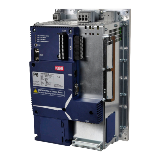
KEB COMBIVERT P6 Instructions For Use Manual (78 pages)
INSTALLATION P6 PITCH INVERTER 18/19/23P6 HOUSING G, R
Brand:
KEB
| Category:
Inverter
| Size: 8 MB
Table of Contents
Preface
3
Signal Words and Symbols
3
More Symbols
3
Laws and Guidelines
4
Warranty and Liability
4
Support
4
Copyright
4
Table of Contents
5
List of Figures
8
List of Tables
10
Glossary
11
Standards for Drive Controllers
13
Product Standards that Apply Directly to the Drive Controller
13
Basic Standards to Which Drive Controller Standards Refer Directly
13
Standards that Are Used in the Environment of the Drive Controller
14
Basic Safety Instructions
15
Target Group
15
Transport, Storage and Proper Use
15
Installation
16
Electrical Connection
17
EMC-Compatible Installation
18
Voltage Test
18
Insulation Measurement
19
Start-Up and Operation
19
Maintenance
20
Repair
20
Disposal
21
Product Description
22
Specified Application
22
Residual Risks
22
Unintended Use
22
Product Features
23
Options
24
Type Code
25
Table 1: Type Code
25
Technical Data
26
Operating Conditions
26
Climatic Ambient Conditions
26
Table 2: Climatic Ambient Conditions
26
Mechanical Ambient Conditions
27
Chemical / Mechanical Active Substances
27
Table 3: Mechanical Ambient Conditions
27
Table 4: Chemical / Mechanical Active Substances
27
Electrical Operating Conditions
28
Device Classification
28
Electromagnetic Compatibility
28
Table 5: Device Classification
28
Table 6: Electromagnetic Compatibility
28
Electrical Data
29
Table 7: Electrical Data
29
Braking Resistor
30
Other Inputs/Outputs of the Power Unit
30
Table 8: Braking Resistor
30
Table 9: Other Inputs / Outputs of the Power Unit
30
Overload Function
31
AC-Motor (18 / 19 / 23P6)
31
Overload Function (OL)
31
Figure 1: Maximum Tripping Time Depending on the Overload for AC Motors
31
Overload Function in the Lower Speed Range (OL2) for 18 / 19P6
32
Figure 2: Output Current Depending on the Output Frequency 18 / 19P6
32
Overload Function in the Lower Speed Range (OL2) for 23P6
33
Figure 3: Output Current Depending on the Output Frequency 23P6
33
DC Motor (19P6 DC)
34
Overload Function (OL)
34
Maximum Output Voltage
34
Figure 4: Maximum Tripping Time Depending on the Output Current at DC Motors
34
Figure 5: Output Voltage Depending on the Output Current
34
Dimensions and Weights
35
Housing G
35
Figure 6: Dimensions and Weight of the COMBIVERT P6 Housing G
35
Mounting Cutout Housing G
36
Figure 7: Mounting Cutout for COMBIVERT P6 (Provided by Customer)
36
Housing R
37
Figure 8: Dimensions and Weight of the COMBIVERT P6 Housing R
37
Mounting Cutout Housing R
38
Figure 9: Mounting Cutout for COMBIVERT P6 Housing R (Provided by Customer)
38
Device Overview
39
Top View of Housing G
39
Rear View of Housing G
39
Figure 10: Top View of Housing G
39
Figure 11: Rear View of Housing G
39
Front View of Housing G
40
Side Views of Housing G
40
Figure 12: Front View of Housing G
40
Figure 13: Side View of Housing G
40
Top View of Housing R
41
Rear View of Housing R
41
Figure 14: Top View of Housing R
41
Figure 15: Rear View of Housing R
41
Front View of Housing R
42
Side Views of Housing R
42
Figure 16: Front View of Housing R
42
Figure 17: Side Views of Housing R
42
Accessories
43
Shield Connection Rail
43
Figure 18: Shield Connection Rail Housing G
43
Figure 19: Shield Connection Rail Housing R
43
Table 10: Shield Connection Rail
43
Power Unit
44
Terminal Block X1A Size 18 / 19
44
Figure 20: Terminal Block X1A Size 18 / 19
44
Terminal Block X1B Size 18 / 19
45
Figure 21: Terminal Block X1B Size 18 / 19
45
Terminal Block X1A Size 23
46
Figure 22: Terminal Block X1A Size 23
46
Terminal Block X1B Size 23
47
Figure 23: Terminal Block X1B Size 23
47
Connecting Cables to X1A and X1B
48
Grey Terminals
48
Figure 24: Grey Terminals
48
Orange Terminals (23P6 Only)
49
Figure 25: Orange Terminals
49
Mains Connection
50
Figure 26: Mains Connection
50
Motor Connection
51
AC Motor Connection
51
DC Motor Connection (19P6 DC Only)
51
Figure 27: Motor Connection AC Motor
51
Figure 28: Motor Connection DC Motor
51
Motor Temperature Detection
52
Figure 29: Connection of a KTY Sensor
52
Table 11: Motor Temperature Monitoring with PTC, KTY or Pt1000
52
Brake Connection
53
Connection of a 24 V - Brake (18/19P6 Only)
53
Connection of a High Voltage Brake
53
Figure 30: Connection of a 24 V-Brake (18/19P6 Only)
53
Figure 31: Connection of a High-Voltage Brake (Option for 18 / 19P6)
53
Figure 32: Connection of a High-Voltage Brake (23P6)
53
Connection of Batteries / Ultracapacitors
54
Figure 33: Connection of Energy Storages
54
Connection of an External Braking Resistor
55
Connection of the Internal Heating
55
Figure 34: Connection of the Internal Heating
55
Connection of the 24V Output (23P6 Only)
56
Figure 35: Connection of the 24V Output (23P6 Only)
56
Control Unit
57
Description of the Indicators and Controls
57
Figure 36: Description of the Indicators and Controls
57
Leds for Program Run and Error Display
58
Address Selector Switch S1
58
Real-Time Clock
58
Table 12: Function of the Led's LD1
58
Connection Instructions Control Unit
59
Assembly of the Wires to PUSH in Terminals
59
Figure 37: Assembly of the Control Cable
59
Table 13: Wire-End Ferrules and Stripping Length
59
Shield Connection
60
D-SUB Sockets and Plugs
60
Description of the Terminals
61
Control Terminal Block X2A
61
Figure 38: X2A Pluggable Terminal Block with Cage Clamp Terminals
61
External Supply of the Control Board
62
Digital Outputs
62
Figure 39: External Supply of the Control Board
62
Figure 40: Digital Outputsdo 0
62
Figure 41: Digital Output DO 8
62
Temperature Inputs
63
Analog Inputs
63
Relay Output
63
Figure 42: Temperature Inputs
63
Figure 43: Analog Inputs
63
Figure 44: Relay Output
63
Control Terminal Block X2B
64
Digital Inputs
64
Figure 45: X2B Pluggable Terminal Block with Cage Clamp Terminals
64
Figure 46: Digital Inputs
64
Encoder Interfaces
65
Pin Assignment Encoder Channel 1 (X3A)
65
Figure 47: Encoder Interfaces
65
Figure 48: Pin Assignment Encoder Channel 1 (X3A)
65
Table 14: Resolver Specification
66
Pin Assignment Encoder Channel 2 (X3B)
67
Encoder Cable
67
Figure 49: Pin Assignment Encoder Channel 2 (X3B)
67
Figure 50: Example for Wiring an Encoder Cable
67
Diagnostic Interface X6A
68
Figure 51: Diagnostic Interface X6A
68
Figure 52: RS232 Cable for Diagnostic Interface
68
Ethernet Interface (X6B)
69
Fieldbus Interface X6C
70
Profibus Dp
70
CAN-Bus
70
Further Bus Systems
70
Figure 53: PROFIBUS DP Interface
70
Figure 54: CAN-Bus Interface
70
Functional Overview
71
Potential Insulation
71
Figure 55: Potential Insulation of the COMBIVERT P6
71
Supply of the Digital Inputs and Outputs
72
Figure 56: Supply of the Digital Inputs and Outputs
72
Certification
73
CE Marking
73
UL Certification
73
Further Informations and Documentation
75
Revision History
76
Advertisement
KEB COMBIVERT P6 Instruction Manual (48 pages)
Brand:
KEB
| Category:
Inverter
| Size: 4 MB
Table of Contents
Table of Contents
3
1 Preface
7
Information on Special Measures
7
Documentation
7
Validity and Liability
8
Copyright
8
Specified Application
9
Product Description
9
Options
10
Unit Identification
11
2 Safety Instructions
12
General Instructions
12
Transport, Storage and Installation
12
Electrical Connection
13
EMC Instructions
16
EMC Conform Installation
16
3 Technical Data
17
Overload Function
18
AC Motor (18/19P6)
18
Figure 1: Maximum Disconnecting Time Depending on the Load at AC Motors
18
Figure 2: Output Current Depending of Theoutput Frequency
18
DC Motor (19P6)
19
Figure 3: Maximum Disconnecting Time Depending on the Output Current at DC Motors
19
Figure 4: Output Voltage Depending on the Output Current
19
Operating Conditions
20
Dimensions and Weights
21
Figure 5: Dimensions and Weight of the COMBIVERT P6
21
Mounting Cutout
22
Figure 6: Mounting Cutout for COMBIVERT P6 (Provided by Customer)
22
4 Hardware
23
Device Overview
23
Terminals
24
Connecting Wires to X1A and X1B
24
Connecting Wires to X2A and X2B
24
Figure 7: Connecting Wires to X1A and X1B
24
Shield Connection Rail
25
Power Unit
25
Description of the Terminal Blocks
25
Terminal Block X1A
25
Figure 8: Shield Connection Rail (Mat.nr. 00P6ZGG-0002)
25
Figure 9: Terminal Strip X1A
25
Terminal Block X1B
26
Mains Connection
26
Figure 10: Terminal Strip X1B
26
Figure 11: Mains Connection
26
Motor Connection
27
AC Motor Connection
27
DC Motor Connection (Option)
27
Figure 12: Motor Connection AC Motor
27
Figure 13: Motor Connection DC Motor
27
Motor Temperature Detection, Terminals T1, T2
28
Brake Control
28
Control of a 24 VDC Brake
28
Figure 14: Connection of a KTY Sensor
28
Figure 15: Connection of a 24 VDC Brake
28
Control of a 150
29
Connection of Batteries/Ultracapacitors
29
Connection of an External Braking Resistor
29
Figure 16: Connection of a High Voltage Brake
29
Figure 17: Connection of Energy Storages
29
Connection of the Internal Heating
30
Figure 18: Connection of the Internal Heating
30
Control Circuit
31
Description of the Terminals and Controls
31
Led's for Program Run and Error Display
32
Address Selector Switch S1
32
Real-Time Clock
32
Control Terminal Block X2A
33
Figure 19: X2A Pluggable Terminal Block with Cage Clamp Terminals
33
External Supply
34
Digital Outputs
34
Figure 20: External Supply of the Control Board
34
Figure 21: Digital Outputsdo 0
34
Figure 22: Digital Output DO 8
34
Temperature Inputs
35
Analog Inputs
35
Relay Output
35
Figure 23: Temperature Inputs
35
Figure 24: Analog Inputs
35
Figure 25: Relay Output
35
Control Terminal Block X2B
36
Digital Inputs
36
Figure 26: X2B Pluggable Terminal Block with Cage Clamp Terminals
36
Figure 27: Digital Inputs
36
Encoder Interfaces
37
Pin Assignment Encoder Channel 1 (X3A)
37
Figure 28: Pin Assignment Encoder Channel 1 (X3A)
37
Pin Assignment Encoder Channel 2 (X3B)
38
Encoder Cable
38
Figure 29: Pin Assignment Encoder Channel 2 (X3B)
38
Figure 30: Example for Wiring an Encoder Cable
38
Diagnostic Interface X6A
39
Ethernet Interface (X6B)
39
Figure 31: Diagnostic Interface X6A
39
Figure 32: RS232 Cable for Diagnostic Interface
39
Fieldbus Interface X6C
40
Profibus Dp
40
Figure 33: PROFIBUS DP Interface
40
CAN-Bus
41
Further Bus Systems
41
Figure 34: CAN-Bus Interface
41
5 Annex a
42
Potential Separation
42
Figure 35: Potential Separation of the COMBIVERT P6
42
Supply of the Digital Inputs and Outputs
43
Figure 36: Supply of the Digital Inputs and Outputs
43
Storage
44
Maintenance
44
Fault Remedy
45
Disposal
45
Certification
45
CE Marking
45
Advertisement
Related Products
KEB COMBIVERT F6
KEB COMBIVERT F4-F
KEB COMBIVERT G6M
KEB COMBIVERT F4-S Series
KEB COMBIVERT F5-B Series
KEB COMBIVERT F5-G Series
KEB COMBIVERT F5-S Series
KEB COMBIVERT F5-M Series
KEB COMBIVERT 14F5 Series
KEB COMBIVERT 16F5 Series
KEB Categories
DC Drives
Controller
Inverter
Control Unit
Industrial Equipment
More KEB Manuals
Login
Sign In
OR
Sign in with Facebook
Sign in with Google
Upload manual
Upload from disk
Upload from URL