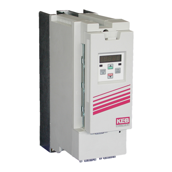
KEB COMBIVERT F5 Instruction Manual
1.5...4.0kw 230 v 1.5...7.5kw 400 v
Hide thumbs
Also See for COMBIVERT F5:
- Applications manual (378 pages) ,
- Reference manual (349 pages) ,
- Instruction manual (196 pages)

Related Manuals for KEB COMBIVERT F5


Summary of Contents for KEB COMBIVERT F5
- Page 1 COMBIVERT GB Instruction Manual Housing D 1.5...4.0 kW 230 V 1.5...7.5 kW 400 V Original manual Mat.No. Rev. 00F50EB-KD00...
-
Page 3: Table Of Contents
Table of Contents Preface ......................5 General ..........................5 Validity and liability ......................5 Copyright ..........................6 1.4 Specified application ......................6 Product description ......................6 Part code ..........................7 Installation instructions ...................... 8 1.7.1 Cooling systems ........................8 1.7.2 Control cabinet installation ..................... 9 Safety and operating instructions .................. - Page 4 Table of Contents Storage ..........................32 A.5.1 Cooling circuit ........................33 Annex B ........................34 B.1 Certification ........................34 B.1.1 CE Marking .......................... 34 B.1.2 UL Marking........................... 34 Annex C ........................36 Installation of water-cooled units ..................36 C.1.1 Heat sink and operating pressure ..................36 C.1.2 Materials in the cooling circuit ....................
-
Page 5: Preface
-, EMC- and operating instructions (Part operating instruc- 1 „Before Starting“ 0000NEB-0000“).This instruction is pro- tions vided with the unit or by download of www.keb.de. Non-observance of the safety instructions leads to the loss of any liability claims. The safety and warning instructions specified in this manual do not lay claim on completeness. This list is not exhaustive. -
Page 6: Copyright
The customer may use the instruction manual as well as further documents or parts from it for internal purposes. Copyrights are with KEB and remain valid in its entirety. All rights reserved. KEB®, COMBIVERT®, KEB COMBICONTROL® and COMBIVIS® are registered trade- marks of Karl E. -
Page 7: Product Description
Preface Product description This instruction manual describes the power circuits of the following units: Unit type: Frequency inverter Series: COMBIVERT F5/F6 Power range: 1.5…4.0 kW / 230 V class 1.5…7.5 kW / 400 V class Housing size: Version: air-cooled Features of the power circuits: •... - Page 8 Preface 1.7 Unit identification 15 F5 K 1 E -3 5 0 A cooling 0, 5, A, F Heat sink (standard) 1, B, G Flat rear 2, C, H Water cooling 3, D, I Convection Encoder interface 0: none Switching frequency; short time current limit; overcurrent limit 2 kHz;...
-
Page 9: Installation Instructions
General Installation instructions 1.8.1 Cooling systems The KEB COMBIVERT F5/F6 is available for different cooling systems: Heat sink with cooling fan (mounted version) The standard version is delivered with heat sink and cooling fan. Special versions The dissipation of power loss must be guaranteed by the machine builder. -
Page 10: Control Cabinet Installation
General 1.8.2 Control cabinet installation Mounting distances Dimen- Distance in mm Distance in sion inch 1) Distance to preceding elements in the cabinet door. Direction of the Front and side view of the coolant inlet cooling fins Coolant outlet Coolant inlet GB - 10... -
Page 11: Safety And Operating Instructions
Safety Instructions Safety and operating instructions Safety and operating instructions for drive converter (in accordance with: Low-Voltage Directive 2006/95/EC) 1. General Drive converter contain electrostatic sensitive components In operation, drive converter depending on their degree of which are liable to damage through improper use. Electric protection, may have live, uninsulated and possibly also components must not be mechanically damaged or de- moving or rotating parts, as well as hot surfaces. -
Page 12: Technical Data
EN 61000-2-4 Frequency changes This product can cause high frequency disturbances in residential areas (category C1) which require noise suppression measures. The specified value is only meet in connection with a corresponding filter. Depending on the operating conditions and corresponding power reduction, higher temperatures are permissible after consulting KEB. GB - 12... -
Page 13: Technical Data Of The 230V Class
9) The output frequency is to be limited in such way that 1/10 of the switching frequency is not exceeded The technical data are for 2/4-pole standard motors. With other pole numbers the inverter must be dimensioned onto the motor rated current. Contact KEB for special or medium fre- quency motors. -
Page 14: Technical Data Of The 400V Class
Technical Data of the 400 V Class Technical data of the 400V class Inverter size Housing size Phases Output rated power [kVA] 1.8 2.8 6.6 8.3 Max. rated motor power [kW] 0.75 1.5 4.0 5.5 7.5 Output rated current [A] 2.6 4.1 12 16.5 Max. -
Page 15: Dc Supply
2.4.2 Internal input circuit The COMBIVERT F5/F6 in D housing corresponds to the inverter type A1. Pay attention to the inverter type in DC interconnection and in operation at regenerative units. Inverter type for COMBIVERT F5/F6 in D housing: A1... -
Page 16: Dimensions And Weights
Technical Data - Dimensions and Weights Dimensions and weights Dimensions mounted version (representation with optional mounting kit) X: F5 without covers 180.5 mm Weight 2.8 kg F5 with cover 182.0 mm Mounting kit: B0F5T88-0001 F5 with operator 194.5 mm 200.5 mm GB - 16... - Page 17 Technical Data - Dimensions and Weights Dimensions Flatrear (representation with optional mounting kit) 42,4 Ø 5,5 X: F5 without covers 142.5 mm Weight 2.7 kg F5 with cover 144.0 mm Mounting kit: B0F5T88-0001 F5 with operator 156.5 mm 162.5 mm GB - 17...
- Page 18 Technical Data - Dimensions and Weights Dimensions through-mount version X: F5 without covers 136 mm Weight 6.6 kg F5 with cover 137,5 mm Mounting kit: B0F5T88-0001 F5 with operator 150 mm 156 mm GB - 18...
- Page 19 Technical Data - Dimensions and Weights Dimensions through-mount version (special version with optional mounting kit) X: F5 without covers 227.5 mm Weight 4.2 kg F5 with cover 229.0 mm Mounting kit: B0F5T88-0001 F5 with operator 241.5 mm Seal 09F4T45-0087 247.5 mm GB - 19...
-
Page 20: Terminal Strips Of The Power Circuit
Terminals Terminal strips of the power circuit Observe input voltage, since 230 V and 400 V class possible All terminal strips following the requirements of the EN 60947-7-1 (IEC 60947-7-1) Name Function Cable cross-sections Terminals No. L1, N 1-phase mains connection L1, L2, L3 3-phase mains connection U, V, W Motor connection... -
Page 21: Accessories
Accessories Accessories 2.7.1 Filter and chokes Voltage class Inverter Filter Mains choke 50 Hz Motor choke 100 Hz size (4 % Uk) (4 % Uk) 07Z1B02-1000 – 230 V 10E5T60-1002 09Z1B02-1000 – 1-phase 10Z1B02-1000 – 10E5T60-1002 07Z1B03-1000 – 230 V 09Z1B03-1000 –... -
Page 22: Connection Power Unit
Connection Power Unit 2.8.1 Mains and motor connection Absolutely pay attention to the supply voltage of the KEB COMBIVERT. A 230 V unit at 400 V mains is destroyed immediately. Exchanging mains and motor connection leads to immediate destruction of the unit. -
Page 23: Selection Of The Motor Cable
T1 T2 Legend DC supply DC fuses Mains contactor KEB COMBIVERT F5 with DC input Motor (see also 2.8.3) Motor protection temperature sensor (also see 2.8.4) 2.8.2 Selection of the motor cable The correct selection and wiring of the motor cable is very important: •... -
Page 24: Connection Of The Motor
Connection Power Unit 2.8.3 Connection of the motor As standard the connection of the motor must be carried out in accordance with the following table: Connection of the motor 230/400 V motor 400/690 V motor 230 V 400 V 400 V 690 V Delta Star... -
Page 25: Temperature Detection T1, T2
Connection Power Unit 2.8.4 Temperature detection T1, T2 In.17 Function of T1, Pn.72 Resistance Display ru.46 Error/Warn- (dr33) (F6 => ru28) < 750 Ω T1-T2 closed – 0.75…1.65 kΩ undefined – (in accord- (reset resistance) ance with 1.65…4 kΩ undefined DIN EN 60947-8) (tripping resistance) > 4 kΩ... -
Page 26: Connection Of A Braking Resistor
Connection Power Unit 2.8.5 Connection of a braking resistor Braking resistors dissipate the produced energy of the motor into heat during generatoric operation. Thus braking resistors can cause very high surface tem- peratures. During assembly pay attention to appropriate protection against con- tact and fire. -
Page 27: 2.8.5.2 Braking Resistor With Overheat Protection
Connection Power Unit 2.8.5.2 Braking resistor with overheat protection This circuit offers a direct protection with defective braking transistor (GTR7).The braking resistor overheats and opens the terminals OH1 and OH2 with defective GTR7. The OH terminals open the holding circuit of the input contactor, so that the input voltage is switched off in error case. -
Page 28: Annex A
Annex Annex A Overload characteristic Time [s] Load [%] 105 110 115 120 125 130 135 140 145 150 160 170 180 190 200 210 220 In this range the characteristic declines dependent on the overcurrent limit (see unit identification). On exceeding a load of 105% the overload integrator starts. -
Page 29: Calculation Of The Motor Voltage
Due to the leakage current the oxide layer is unrenewed. If the capacitor starts running with rated voltage there is a high leakage current which can destroy the capacitor. In order to avoid defectives, the KEB COMBIVERT must be started up depending on the stor- age period in accordance with the following specification: Storage period <... -
Page 30: Cooling Circuit
Storage period > 3 years • Input voltages as before, however double the times per year. Eventually change capaci- tors. After expiration of this start-up the KEB COMBIVERT can be operated on nominal rating con- ditions or delivered to a new storage. A.4.3 Cooling circuit The cooling circuit must be completely empty if a unit shall be switched off for a longer period. -
Page 31: Annex B
B.1.2 UL Marking Acceptance according to UL is marked at KEB inverters with the adjacent logo on the type plate. To be conform according to UL for use on the North American and Canadian Market the fol- lowing additionally instructions must be observed (original text of the UL-File): •... - Page 32 Annex • “D Housing - Series Combivert, Cat. Nos. 07, 09, 10, 12, 13 or 14, followed by F5, followed by B or C, followed by 0, 1, 2, 3, A, B, C or D, followed by D-, followed by four suffixes. D Housing - Series Combivert, Cat. No. 07, 09, 10, 12, 13 or 14, followed by F5, followed by B or C, followed by 0, 1, 2, 3, A, B, C or D, followed by D-, followed by three suffixes and followed by 4 or E or J.
- Page 33 Annex Branch Circuit Protection: Type E Self Protected Manual Motor Controllers for Drive series inverters F5–D and F6-D. Listed (NKJH) Type E Self Protected Manual Motor Controllers. Type and manufacturer and electrical ratings as specified below: 240V devices: Inverter Drive input rat- Self Protected Self Protected model Manual Motor Controller Type...
- Page 34 Only for F6 housing E series: “For Connector CN300 on Control Board: Only use KEB Cable assembly Cat.No. 00H6L41-0xxx or 00H6L53-2xxx (where x = any digit) and use strain relief provisions as described below:” Strain relief at housing D by use of mounting kit B0F5T88-0001 or -0002...
-
Page 35: Annex D
Annex Annex D Changing the response threshold of the braking transistor (not valid for control type „BASIC“) To avoid a premature switching of the brake transistor at an input rated voltage of 480 Vac, the response threshold must be controlled or adjusted according to the following graphic. FUNC. - Page 36 KEB Italia S.r.l. fon: +32 5443 7860 • fax: +32 5443 7898 Via Newton, 2 • I-20019 Settimo Milanese (Milano) mail: vb.belgien@keb.de fon: +39 02 3353531 • fax: +39 02 33500790 net: www.keb.de • mail: kebitalia@keb.it KEB Power Transmission Technology (Shanghai) Co.,Ltd. No. 435 Qianpu Road, Chedun Town, Songjiang District, KEB Japan Ltd. CHN-Shanghai 201611, P.R. China 15–16, 2–Chome, Takanawa Minato-ku fon: +86 21 37746688 • fax: +86 21 37746600 J-Tokyo 108-0074 net: www.keb.de • mail: info@keb.cn fon: +81 33 445-8515 • fax: +81 33 445-8215...
Need help?
Do you have a question about the COMBIVERT F5 and is the answer not in the manual?
Questions and answers