Sign In
Upload
Manuals
Brands
Binder Manuals
Dryer
vdl 23
Binder vdl 23 Manuals
Manuals and User Guides for Binder vdl 23. We have
4
Binder vdl 23 manuals available for free PDF download: Operating Manual, Mounting Instructions
Binder vdl 23 Operating Manual (235 pages)
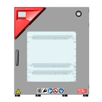
Vacuum Drying oven
Brand:
Binder
| Category:
Oven
| Size: 9.5 MB
Table of Contents
Table of Contents
2
1 Safety
10
Personnel Qualification
10
Operating Manual
10
Legal Considerations
11
Structure of the Safety Instructions
12
Signal Word Panel
12
Safety Alert Symbol
12
Explosion Protection Symbol
12
Pictograms in this Manual
13
Word Message Panel Structure
14
Localization / Position of Safety Labels on the Chamber
14
Figure 1: Position of Labels on the Chamber (Examples)
14
Type Plate
15
Figure 2: Type Plate (Example of VDL 115)
15
Safety Instructions on Installing and Operating the Vacuum Drying Oven
16
Safety Instructions on Installation and Ambient Conditions of the Chamber
16
Aeration / Ventilation of the Installation Site
17
No Installation in Potentially Explosive Areas of Zone 1 or 0
17
Equipotential Bonding According to the Grounding Concept
18
Accessibility to the Disconnection from the Power Grid
18
Technical Ventilation (Extraction)
18
Safety Instructions on Vacuum Supply
19
Selection and Location of a Suitable Pump
19
Observing the Permissible Gas Inlet Temperature
20
Technical Ventilation (Extraction)
20
Safety Instructions on the Charging Material
21
Safety Instructions on Operating the Vacuum Drying Oven
22
Ex Classification of the Chamber and Immediate Surroundings
25
Intended Use
27
Foreseeable Misuse
29
Residual Risks
31
2 Operator Responsibility, Documentation, and Measures
34
Risk Assessment / Explosion Protection Document
34
Employee Training and Protocols
34
Operating Instructions
35
Safety Data Sheets
35
Protective Equipment
35
Standard Operating Procedures (Sops)
36
Testing and Maintenance
37
Operation Log
37
3 Description of the Equipment
39
Manufacturer's Safety Plan: Protective Measures and Equipment
40
Chamber Overview
45
Figure 3: VDL 115 with MB2 Controller
45
Figure 4: VDL 115 with Optional RD4 Controller
45
Instrument Panel with Regular MB2 Controller
46
Instrument Panel with Optional RD4 Controller
46
Connections on the Rear of the Chamber
46
Figure 5: Instrument Panel with MB2 Program Controller and USB Interface
46
Figure 6: Instrument Panel with RD4 Controller and USB Interface
46
Figure 7: Chamber Rear (Example: VDL 115)
46
Figure 8: Rear Control Panel VDL with Options
47
Area Classification, Information for the Zone Classification
48
Area Classification Inside the Chamber
49
Figure 9: Area Classification of the Closed Chamber (View Without Housing, Insulation, Heater and Outer Chamber)
49
Area Classification in the Surroundings of the Chamber
50
Figure 10: Area Classification in the Surroundings of the Chamber (Schematic Representation)
50
Area Classification in the Surroundings of the Chamber: Extraction Lead to the Pump, Location of the Pump
51
Figure 11: Area Classification in the Surroundings of the Chamber During Operation (Example)
51
4 Completeness of Delivery, Transportation, Storage, and Installation
52
Unpacking, and Checking Equipment and Completeness of Delivery
52
Guidelines for Safe Lifting and Transportation
53
Storage
53
5 Location of Installation and Ambient Conditions
53
General Requirements for Installation
53
Ventilation and Extraction (Technical Ventilation)
55
Ventilation for Heat Removal in Normal Operation
55
Technical Ventilation When Loading and Unloading Charging Material and Emptying the Condensate Catchpot of the Pump
55
Air Supply (Breaking the Vacuum) During Operation with Inert Gas
56
Equipotential Bonding
56
Ambient Conditions
56
Compressed Air / Inert Gas Supply for Sweeping the Area for Electrical Equipment
56
Fire Extinguisher
56
Lightning Protection Device
57
6 Installation and Connections
57
Vacuum Expansion Racks and Rack Holders
57
Figure 12: Operating the Expansion Racks
58
Compressed Air / Inert Gas Connection for Sweeping the Area for Electrical Equipment and Triangle Instrument Box
59
Figure 13: Compressed Air Connection on the Pressure Regulator
59
Figure 14: Pressure Regulator for Compressed Air Sweeping on the Chamber Rear, Top Right
60
Figure 15: Analog Pressure Display (Manometer) for Compressed Air Sweeping on the Chamber Front
60
Setting the Overpressure for Sweeping with Compressed Air / Inert Gas
60
Pump Module (Option)
61
Figure 16: VDL Mounted on Pump Module
61
Figure 17: Pump Module, Rear View (Example Size 115)
61
Achieving Equipotential Bonding Acc. to the Grounding Plan
62
Mounting
62
Connection of an Extraction System at the Pump Module
63
Vacuum Connection
63
Figure 18: Position of the Vacuum Connection on the Chamber Rear (Example Size 115)
63
Instructions for Using Vacuum Pumps
64
Figure 19: Vacuum Pump VP 4 (MZ2C EX)
66
Vacuum Pump VP4 (Option)
66
Installation of the Vacuum Pump VP4 in the Pump Module (Option)
67
Note on the Use of a Flame Arrester
68
ATEX Connection Kit for Vacuum Pump VP4 (Option)
69
Connecting Inert Gas Supply
69
Achieving Equipotential Bonding / Grounding Concept
70
Figure 20: Possibilities of Grounding (Schematic Representation)
70
Figure 21: Mounting the Grounding Cable on the VDL
71
Electrical Connection
72
7 Explosion Safety Tests before Commissioning
74
Scope of the Functional Test
74
Explosion Protection Plan
74
Objective of Testing
75
Testing before Initial Commissioning
75
Scope of the Test
75
Testing the Plausibility of the Explosion Protection Plan and Measures
75
Verifying the Implementation of Measures
75
Checking the Deadlines for the Recurring Tests
76
Verifying the Maintenance Plan
76
Tests of Technical Ventilation Systems, Gas Warning Devices, Inerting Devices, Devices, Protective Systems or Safety, Control or Regulating Devices, and Other Technical Devices for Explosion Protection
77
Inspection after Changes Requiring Review
77
Recurring Tests for the Explosive Safety of the System
77
8 Functional Overview and Menu Structure of the Controller
78
MB2 Controller
78
Figure 22: Normal Display of the MB2 Program Controller (Sample Values)
78
Figure 23: Operating Functions of the MB2 Controller in Normal Display (Example Values)
79
Operating Functions in Normal Display
79
Display Views: Normal Display, Program Display, Chart-Recorder Display
80
MB2 Controller Icons Overview
81
MB2 Controller Menu Structure
83
Main Menu
84
Settings" Submenu
85
Service" Submenu
85
MB2 Controller Operating Modes
83
Principle of Controller Entries
86
RD4 Controller
87
Figure 24: Normal Display of the RD4 Controller (Sample Values)
87
Menu Structure of the Controller and Access Levels
88
Performance During and after Power Failures
89
MB2 Controller
89
RD4 Controller
90
9 Start up and Performing the Drying Process
90
Requirements for Safe Commissioning
90
Overview of the Drying Process
91
Sweeping the Area for Electrical Equipment and Triangualr Instriment Box
93
Condition after Establishing the Power Connection
93
Standby Mode Turning on and off the Vacuum Drying Oven
94
MB2 Controller
94
RD4 Controller
95
Controller Settings Upon Start up
95
MB2 Controller
95
RD4 Controller
96
Loading
97
Evacuation
98
Breaking the Vacuum (Flooding)
99
Ventilation after Completing the Drying Procedure (Flooding with Ambient Air or Inert Gas)
99
Operation with Inert Gas
99
Ventilation / Breaking the Vacuum in Case of a Power Failure
100
Unloading the Loading Material
101
Removing the Full Condensate Catchpot of the Pump
102
Preparing a New Drying Process
102
10 Set-Point Entry
103
MB2 Controller
103
Set-Point Entry through the "Setpoints" Menu
103
Direct Setpoint Entry Via Normal Display
104
RD4 Controller
105
Temperature Set-Point Entry
105
Pressure Set-Point Entry
105
11 Setting Special Controller Functions
106
Menu Structure
106
MB2 Controller
106
Functions On/Off" Menu
106
Control On/Off" Menu
107
RD4 Controller
107
Functions On/Off" Menu
107
Quick Access Menu
108
Using the Optional Connection "GAS/AIR 2" for Ventilation
108
MB2 Controller
109
RD4 Controller
109
Close All Valves
110
MB2 Controller
110
RD4 Controller
110
Activating / Deactivating Temperature Control
111
MB2 Controller
111
RD4 Controller
111
Activating / Deactivating Pressure Control
112
MB2 Controller
112
RD4 Controller
113
Drying Monitoring
114
Figure 25: Schematic Timing of the Drying Process and Drying Monitoring
114
MB2 Controller
115
RD4 Controller
116
12 Authorization Levels and Password Protection
116
MB2 Controller
116
User Management, Authorization Levels and Password Protection
116
Log in
120
Log out
121
User Change
121
Password Assignment and Password Change
122
Password Change
122
Deleting the Password for an Individual Authorization Level
124
New Password Assignment for "Service" or "Admin" Authorization Level When the Password Function was Deactivated
125
Activation Code
126
RD4 Controller
127
Password Request
127
Assign and Modify a Password
127
Assign and Modify the User Password
128
Assign and Modify the Admin Password
128
13 General Controller Settings and Information
129
MB2 Controller
129
Selecting the Controller's Menu Language
129
Setting Date and Time
129
Selecting the Temperature Unit
131
Display Configuration
131
Adapting the Display Parameters
131
Touchscreen Calibration
132
Event List
133
Service Contact Page
133
Current Operating Parameters
134
Technical Chamber Information
134
RD4 Controller
135
Selecting the Controller's Menu Language
135
Selecting the Temperature Unit
135
Setting the Current Date
136
Setting the Current Time
137
Function "Language Selection at Restart
137
Setting the Chamber Address
138
Display Brightness
138
Display of the Inner Chamber Temperature and the Heating Temperature
138
14 Temperature Safety Devices
139
Over Temperature Protective Device Class 2 (Thermal Switch)
139
Overtemperature Safety Controller Class 2
139
Safety Controller Mode
139
Setting the Safety Controller
140
MB2 Controller
140
RD4 Controller: Setting the Safety Controller Mode
141
RD4 Controller: Setting the Safety Controller Value
141
Message and Measures in the State of Alarm
142
MB2 Controller
142
RD4 Controller
142
Function Check
143
15 Tolerance Range Settings
143
MB2 Controller
143
Setting the Alarm Delay Times and the Tolerance Ranges
143
Alarm Condition
144
RD4 Controller
144
Setting the Delay Time for Temperature Tolerance Range Alarm
144
Setting the Temperature Tolerance Range
144
Setting the Delay Time for Pressure Tolerance Range Alarm
145
Setting the Pressure Tolerance Range
145
State of Alarm
145
16 Notification and Alarm Functions
146
Information Messages
146
MB2 Controller
146
RD4 Controller
147
Alarm Messages
149
MB2 Controller
149
RD4 Controller
150
Resetting an Alarm
151
MB2 Controller
151
RD4 Controller
151
Activating / Deactivating the Audible Alarm (Buzzer)
152
MB2 Controller
152
RD4 Controller
152
17 Mb2 Controller: Timer Program (Stopwatch Function)
153
Starting a Timer Program
153
Performance During Program Delay Time
154
Stopping a Running Timer Program
154
Pausing a Running Timer Program
154
Cancelling a Running Timer Program
154
Performance after the End of the Program
154
18 Mb2 Controller: Time Programs
155
Starting an Existing Time Program
155
Performance During Program Delay Time
156
Stopping a Running Time Program
156
Pausing a Running Time Program
156
Cancelling a Running Time Program
156
Performance after the End of the Program
157
Creating a New Time Program
158
Program Editor: Program Management
158
Deleting a Time Program
159
Section Editor: Section Management
160
Add a New Program Section
161
Copy and Insert or Replace a Program Section
161
Deleting a Program Section
162
Value Entry for a Program Section
163
Section Duration
163
Set-Point Ramp and Set-Point Step
164
Special Controller Functions
165
Setpoint Entry
166
Tolerance Range
166
Repeating One or Several Sections Within a Time Program
167
Saving the Time Program
168
19 Mb2 Controller: Week Programs
169
Starting an Existing Week Program
169
Cancelling a Running Week Program
170
Creating a New Week Program
171
Program Editor: Program Management
172
Deleting a Week Program
173
Section Editor: Section Management
174
Add a New Program Section
175
Copy and Insert or Replace a Program Section
175
Deleting a Program Section
176
Value Entry for a Program Section in the Section View
176
Set-Point Ramp and Set-Point Step Modes
176
Weekday
177
Start Time
177
Setpoint Entry
178
Special Controller Functions
178
20 Network and Communication
179
MB2 Controller
179
Ethernet
179
Configuration
179
Display of MAC Address
180
Web Server
180
E-Mail
181
RD4 Controller: Ethernet Network Settings
182
Showing the Network Settings
182
Showing the Chamber's MAC Address
182
Showing the IP Address
182
Showing the Subnet Mask
183
Showing the Standard Gateway
183
Showing the DNS Server Address
183
Showing the DNS Chamber Name
184
Changing the Configuration of the Network Settings
184
Selecting the Type of IP Address Assignment (Automatic / Manual)
184
Selecting the Type of Assignment of the DNS Server Address (Automatic / Manual)
185
Assigning the IP Address
185
Setting the Subnet Mask
186
Setting the Standard Gateway
186
Assigning the DNS Server Address
187
21 Rd4 Controller: Data Recorder
187
Recorded Data
188
Storage Capacity
188
Setting the Storage Rate for the "DL1" Recorder Data
188
Deleting the Data Recorder
189
22 Usb Menu: Data Transfer Via Usb Interface
189
Using the USB Connection During Chamber Operation
189
MB2 Controller
189
RD4 Controller
190
Connecting the USB Stick
191
Import Function
191
Export Functions
191
Ongoing Data Transfer
192
Error During Data Transmission
192
Removing the USB Stick
192
23 Mb2 Controller: Chart Recorder Display
193
Views
193
Show and Hide Legend
193
History Display
193
Setting the Parameters
196
24 Reference Measurements
197
Checking the Temperature in the Inner Chamber
197
Checking the Controller Display
197
Checking the Spatial Temperature Exactitude
197
25 Options
198
APT-COM™ 4 Multi Management Software (Option)
198
Analog Outputs for Temperature and Pressure (Option)
198
Measuring Access Port for Vacuum, 9 Poles (Option)
198
Figure 26: Pin Configuration of the SUB-D Socket „Analog Output" (8) for the Analog Outputs Option
198
Figure 27: Measuring Connection (12) with Measuring Access Port and Supplied Plug
198
Object Temperature Display with Flexible Pt 100 Temperature Sensor (Option)
199
Connection of the Object Temperature Sensor
199
Display on the RD4 Controller
200
Display on the MB2 Controller
200
Figure 28: Measuring Connection (12) with Measuring Access Port
200
26 Cleaning and Decontamination
201
Safety Instructions on Cleaning and Decontamination
201
Cleaning
202
Decontamination / Chemical Disinfection
203
27 Maintenance and Service, Troubleshooting, Repair, Testing
204
General Information, Personnel Qualifications
204
Simple Troubleshooting
205
Maintenance, Service
208
Safety Instructions on Maintenance Work
208
Maintenance Intervals
209
Service Reminder
210
MB2 Controller
210
RD4 Controller
210
BINDER Service Contact Data
210
Sending the Chamber Back to BINDER Gmbh
211
28 Disposal
211
Disposal of the Transport Packing
211
Decommissioning
212
Disposal of the Chamber in the Federal Republic of Germany
212
Disposal of the Chamber in the Member States of the EU Except for the Federal Republic of Germany
213
Disposal of the Chamber in Non-Member States of the EU
214
29 Technical Description
215
Factory Calibration and Adjustment
215
Over Current Protection
215
VDL / VDL-UL Technical Data
215
Equipment and Options (Extract)
217
Accessories and Spare Parts (Extract)
218
Dimensions
220
Vdl 23
220
Vdl 56
221
Vdl 115
222
30 Index
223
31 Certificates and Declarations of Conformity
225
EU Declaration of Conformity
225
32 Product Registration
228
33 Contamination Clearance Certificate
229
For Chambers Located Outside USA and Canada
229
For Chambers Located in USA and Canada
232
Advertisement
Binder vdl 23 Operating Manual (207 pages)
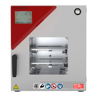
Vacuum Drying Oven with microprocessor program controller MB2
Brand:
Binder
| Category:
Oven
| Size: 8.96 MB
Table of Contents
Table of Contents
2
1 Safety
8
Personnel Qualification
8
Operating Manual
8
Legal Considerations
9
Structure of the Safety Instructions
10
Signal Word Panel
10
Safety Alert Symbol
10
Explosion Protection Symbol
10
Pictograms in this Manual
11
Word Message Panel Structure
12
Localization / Position of Safety Labels on the Chamber
12
Figure 1: Position of Labels on the Chamber (Example)
12
Type Plate
13
Figure 2: Type Plate (Example of VDL 115)
13
Safety Instructions on Installing and Operating the Vacuum Drying Oven
14
Safety Instructions on Installation and Ambient Conditions of the Chamber
14
Aeration / Ventilation of the Installation Site
15
No Installation in Potentially Explosive Areas of Zone 1 or 0
15
Equipotential Bonding According to the Grounding Concept
16
Accessibility to the Disconnection from the Power Grid
16
Technical Ventilation (Extraction)
16
Safety Instructions on Vacuum Supply
17
Selection and Location of a Suitable Pump
17
Observing the Permissible Gas Inlet Temperature
18
Technical Ventilation (Extraction)
18
Safety Instructions on the Charging Material
19
Safety Instructions on Operating the Vacuum Drying Oven
20
Ex Classification of the Chamber and Immediate Surroundings
23
Intended Use
25
Foreseeable Misuse
27
Residual Risks
29
2 Operator Responsibility, Documentation, and Measures
32
Risk Assessment / Explosion Protection Document
32
Employee Training and Protocols
32
Operating Instructions
33
Safety Data Sheets
33
Protective Equipment
33
Standard Operating Procedures (Sops)
34
Testing and Maintenance
35
Operation Log
35
3 Description of the Equipment
37
Manufacturer's Safety Plan: Protective Measures and Equipment
38
Chamber Overview
43
Figure 3: VDL 115 with MB2 Controller
43
Triangular Instrument Box with MB2 Controller
44
Connections on the Rear of the Chamber
44
Figure 4: Triangular Instrument Box (Controller Housing) with MB2 Program Controller and USB Interface
44
Figure 5: Chamber Rear (Example: VDL 115)
44
Figure 6: Rear Connection Panel VDL with Options
45
Area Classification, Information for the Zone Classification
46
Area Classification Inside the Chamber
47
Figure 7: Area Classification of the Closed Chamber (View Without Housing, Insulation, Heater and Outer Chamber)
47
Area Classification in the Surroundings of the Chamber
48
Figure 8: Area Classification in the Surroundings of the Chamber (Schematic Representation)
48
Area Classification in the Surroundings of the Chamber: Extraction Lead to the Pump, Location of the Pump
49
Figure 9: Area Classification in the Surroundings of the Chamber During Operation (Example)
49
4 Completeness of Delivery, Transportation, Storage, and Installation
50
Unpacking, and Checking Equipment and Completeness of Delivery
50
Guidelines for Safe Lifting and Transportation
51
Storage
51
5 Location of Installation and Ambient Conditions
51
General Requirements for Installation
51
Ventilation and Extraction (Technical Ventilation)
53
Ventilation for Heat Removal in Normal Operation
53
Technical Ventilation During Chamber Operation and When Emptying the Condensate Catchpot of the Pump
53
Air Supply (Breaking the Vacuum) During Operation with Inert Gas
54
Equipotential Bonding
54
Ambient Conditions
54
Compressed Air / Inert Gas Supply for Sweeping the Area for Electrical Equipment and Controller Housing
54
Fire Extinguisher
54
Lightning Protection Device
55
6 Installation and Connections
55
Vacuum Expansion Racks and Rack Holders
55
Figure 10: Operating the Expansion Racks
56
Mounting the Pressure Regulator
57
Figure 11: Mounting the Pressure Regulator on the Chamber Rear
57
Connecting Compressed Air / Inert Gas Supply for Sweeping the Area for Electrical Equipment and Controller Housing
59
Figure 12: Compressed Air Connection on the Pressure Regulator
59
Pump Module (Option)
60
Figure 13: VDL Mounted on Pump Module
60
Figure 14: Pump Module, Rear View (Example Size 115)
60
Achieving Equipotential Bonding Acc. to the Grounding Plan
61
Mounting
61
Connection of an Extraction System at the Pump Module
62
Vacuum Connection
62
Figure 15: Position of the Vacuum Connection on the Chamber Rear (Example Size 115)
62
Instructions for Using Vacuum Pumps
63
Figure 16: Vacuum Pump VP 4 (MZ2C EX)
65
Vacuum Pump VP4 (Option)
65
Installation of the Vacuum Pump VP4 in the Pump Module (Option)
66
Note on the Use of a Flame Arrester
67
ATEX Connection Kit for Vacuum Pump VP4 (Option)
68
Connecting Inert Gas Supply
68
Mounting the Tilt Protection Holders
69
Figure 17: Variable Length of the Tilt Protection Holder Depending on the Bend
69
Achieving Equipotential Bonding / Grounding Concept
70
Figure 18: Possibilities of Grounding (Schematic Representation)
70
Figure 19: Mounting the Grounding Cable on the VDL
71
Electrical Connection
72
7 Explosion Safety Tests before Commissioning
74
Scope of the Functional Test
74
Explosion Protection Plan
74
Objective of Testing
75
Testing before Initial Commissioning
75
Scope of the Test
75
Testing the Plausibility of the Explosion Protection Plan and Measures
75
Verifying the Implementation of Measures
75
Checking the Deadlines for the Recurring Tests
76
Verifying the Maintenance Plan
76
Tests of Technical Ventilation Systems, Gas Warning Devices, Inerting Devices, Devices, Protective Systems or Safety, Control or Regulating Devices, and Other Technical Devices for Explosion Protection
77
Inspection after Changes Requiring Review
77
Recurring Tests for the Explosive Safety of the System
77
8 Functional Overview and Menu Structure of the Controller
78
Figure 20: Normal Display of the MB2 Program Controller (Sample Values)
78
Operating Functions in Normal Display
79
Figure 21: Operating Functions of the MB2 Controller in Normal Display (Example Values)
79
Display Views: Normal Display, Program Display, Chart-Recorder Display
80
MB2 Controller Icons Overview
81
MB2 Controller Operating Modes
83
MB2 Controller Menu Structure
83
Main Menu
84
Settings" Submenu
85
Service" Submenu
85
Principle of Controller Entries
86
Performance During and after Power Failures
87
9 Start up and Performing the Drying Process
88
Requirements for Safe Commissioning
88
Setting the Pressure Regulator for Sweeping with Compressed Air / Inert Gas
89
Figure 22: Pressure Regulator for Compressed Air Sweeping on the Chamber Rear, Top Right
89
Figure 23: Analog Pressure Display (Manometer) for Compressed Air Sweeping on the Chamber Front
89
Overview of the Drying Process
90
Sweeping the Area for Electrical Equipment and Controller Housing (Triangular Instrument Box)
92
Sweeping before Starting up the Chamber
92
Sweeping During Chamber Operation
92
Condition after Establishing the Power Connection
92
Standby Mode Turning on and off the Vacuum Drying Oven
93
Controller Settings Upon Start up
94
Loading
95
Evacuation
97
Breaking the Vacuum (Flooding)
97
Ventilation after Completing the Drying Procedure (Flooding with Ambient Air or Inert Gas)
97
Operation with Inert Gas
98
Ventilation / Breaking the Vacuum in Case of a Power Failure
98
Ventilation before Completing the Drying Procedure (Flooding with Ambient Air or Inert Gas)
99
Unloading the Loading Material
99
Removing the Full Condensate Catchpot of the Pump
100
Preparing a New Drying Process
100
10 Set-Point Entry
101
Set-Point Entry through the "Setpoints" Menu
101
Direct Setpoint Entry Via Normal Display
102
11 Setting Special Controller Functions
103
Menu Structure
103
Functions On/Off" Menu
103
Control On/Off" Menu
104
Using the Optional Universal Connection "GAS/AIR 2" for Ventilation
104
Close All Valves
105
Activating / Deactivating Temperature Control
106
Activating / Deactivating Pressure Control
107
Drying Monitoring
108
Figure 24: Schematic Timing of the Drying Process and Drying Monitoring
108
12 Authorization Levels and Password Protection
110
User Management, Authorization Levels and Password Protection
110
Log in
113
Log out
114
User Change
114
Password Assignment and Password Change
115
Password Change
115
Deleting the Password for an Individual Authorization Level
117
New Password Assignment for "Service" or "Admin" Authorization Level When the Password Function was Deactivated
118
Activation Code
119
13 General Controller Settings and Information
120
Selecting the Controller's Menu Language
120
Setting Date and Time
120
Selecting the Temperature Unit
122
Display Configuration
122
Adapting the Display Parameters
122
Touchscreen Calibration
123
Event List
124
Service Contact Page
124
Current Operating Parameters
125
Technical Chamber Information
125
14 Temperature Safety Devices
126
Safety Temperature Limiter (TL) Class 2
126
Overtemperature Safety Controller Class 2
126
Safety Controller Mode
126
Setting the Safety Controller
127
Message and Measures in the State of Alarm
128
Function Check
128
15 Tolerance Range Settings
129
Setting the Alarm Delay Times and the Tolerance Ranges
129
Alarm Condition
129
16 Notification and Alarm Functions
130
Information Messages
130
Alarm Messages
131
Resetting an Alarm
132
Activating / Deactivating the Audible Alarm (Buzzer)
133
Test Alarm of the Safety Temperature Limiter (TL)
133
17 Timer Program (Stopwatch Function)
135
Starting a Timer Program
135
Performance During Program Delay Time
136
Stopping a Running Timer Program
136
Pausing a Running Timer Program
136
Cancelling a Running Timer Program
136
Performance after the End of the Program
136
18 Time Programs
137
Starting an Existing Time Program
137
Performance During Program Delay Time
138
Stopping a Running Time Program
138
Pausing a Running Time Program
138
Cancelling a Running Time Program
138
Performance after the End of the Program
139
Creating a New Time Program
140
Program Editor: Program Management
140
Deleting a Time Program
141
Section Editor: Section Management
142
Add a New Program Section
143
Copy and Insert or Replace a Program Section
143
Deleting a Program Section
144
Value Entry for a Program Section
145
Section Duration
145
Set-Point Ramp and Set-Point Step
146
Special Controller Functions
147
Setpoint Entry
148
Tolerance Range
148
Repeating One or Several Sections Within a Time Program
149
Saving the Time Program
150
19 Week Programs
151
Starting an Existing Week Program
151
Cancelling a Running Week Program
152
Creating a New Week Program
153
Program Editor: Program Management
154
Deleting a Week Program
155
Section Editor: Section Management
156
Add a New Program Section
157
Copy and Insert or Replace a Program Section
157
Deleting a Program Section
158
Value Entry for a Program Section in the Section View
158
Set-Point Ramp and Set-Point Step Modes
158
Weekday
159
Start Time
159
Setpoint Entry
159
Special Controller Functions
160
20 Network and Communication
160
Ethernet
160
Configuration
160
Display of MAC Address
161
Web Server
161
E-Mail
162
21 Usb Menu: Data Transfer Via Usb Interface
163
Using the USB Connection During Chamber Operation
163
22 Chart Recorder Display
165
Views
165
Show and Hide Legend
165
History Display
165
Setting the Parameters
168
23 Reference Measurements
169
Checking the Temperature in the Inner Chamber
169
Checking the Controller Display
169
Checking the Spatial Temperature Exactitude
169
24 Options
170
APT-COM™ 4 Multi Management Software (Option)
170
Analog Outputs for Temperature and Pressure (Option)
170
Measuring Access Port for Vacuum, 9 Poles (Option)
170
Figure 25: Pin Configuration of the SUB-D Socket „Analog Output" (8) for the Analog Outputs Option
170
Figure 26: Measuring Connection (12) with Measuring Access Port and Supplied Plug
170
Object Temperature Display with Flexible Pt 100 Temperature Sensor (Option)
171
Connection of the Object Temperature Sensor
171
Figure 27: SUB-D Socket to Connect the Optional Pt 100 in the Rear Connection Panel of the Chamber
171
Display on the MB2 Controller
172
Figure 28: Measuring Connection (12) with Measuring Access Port
172
25 Cleaning and Decontamination
173
Safety Instructions on Cleaning and Decontamination
173
Cleaning
174
Decontamination / Chemical Disinfection
175
26 Maintenance and Service, Troubleshooting, Repair, Testing
176
General Information, Personnel Qualifications
176
Simple Troubleshooting
177
Maintenance, Service
180
Safety Instructions on Maintenance Work
180
Maintenance Intervals
181
Service Reminder
182
BINDER Service Contact Data
182
Sending the Chamber Back to BINDER Gmbh
183
27 Disposal
183
Disposal of the Transport Packing
183
Decommissioning
184
Disposal of the Chamber in the Federal Republic of Germany
184
Disposal of the Chamber in the Member States of the EU Except for the Federal Republic of Germany
185
Disposal of the Chamber in Non-Member States of the EU
186
28 Technical Description
187
Factory Calibration and Adjustment
187
Over Current Protection
187
VDL / VDL-UL Technical Data
187
Equipment and Options (Extract)
189
Accessories and Spare Parts (Extract)
190
Dimensions
192
Vdl 23
192
Vdl 56
193
Vdl 115
194
29 Index
195
30 Certificates and Declarations of Conformity
197
EU Declaration of Conformity
197
31 Product Registration
200
32 Contamination Clearance Certificate
201
For Chambers Located Outside USA and Canada
201
For Chambers Located in USA and Canada
204
Binder vdl 23 Operating Manual (109 pages)
vacuum drying ovens for flammable solvents
Brand:
Binder
| Category:
Dryer
| Size: 8.17 MB
Table of Contents
Table of Contents
2
1 Safety
5
Legal Considerations
5
Structure of the Safety Instructions
5
Signal Word Panel
5
Safety Alert Symbol
6
Pictograms
6
Word Message Panel Structure
7
Localization / Position of Safety Labels on the Chamber
7
Type Plate
8
General Safety Instructions on Installing and Operating the Vacuum Drying Oven
9
Safety Instructions on Installation and Ambient Conditions
10
Safety Instructions on Vacuum Supply
11
Safety Instructions on the Charging Material
12
Safety Instructions on Operating the Vacuum Drying Oven
14
Intended Use
17
Operation Log
17
2 Description of the Equipment
19
Safety Equipment
20
Overview of the Oven
21
VDL Control Panel
22
Connections at the Rear of the Chamber
23
Temperature Setting" Information Panel (Ignition Temperature Vs. Drying Temperature)
24
Overview of the Zone Classification of the Ovens
25
3 Completeness of Delivery, Transportation, Storage, and Installation
27
Unpacking, and Checking Equipment and Completeness of Delivery
27
Guidelines for Safe Lifting and Transportation
28
Storage
28
Location of Installation and Ambient Conditions
28
4 Installation and Connections
30
Vacuum Expansion Racks
30
Vacuum Connection
31
Notes Regarding Use of Vacuum Pumps of Other Manufacturers
33
Inert Gas Connection
33
Compressed Air / Inert Gas Connection for Sweeping the Area for Electrical Equipment
34
Electrical Connection
35
5 Start up
36
Settings at the RD3 Program Controller
36
General Indications
37
6 Fixed Value Entry Mode
39
7 Week Program Editor
41
Program Table Template for the Week Program Editor
43
Programming Example of the Week Program Editor
44
Desired Time Function
44
Proceeding Overview
44
Proceeding in Detail
45
8 Program Editor
50
Selecting between Set-Point Ramp and Set-Point Step
50
Programming with Setting "Ramp" (Default Setting)
50
Programming with Setting "Step
53
General Notes on Programming Temperature Transitions
54
Set-Point Entry for Program Operation
54
Program Table Template
57
Deleting a Program Section
58
9 Program Start Level
59
10 User Level
62
11 Performance in Case of Failures
68
Performance after Power Failures
68
Alarm Messages
68
12 Safety Device Class 2 (Din 12880:2007)
68
13 Reference Measurements. Checking the Temperature in the Inner Chamber
70
14 Commissioning the Vacuum
70
Evacuation
71
Breaking the Vacuum (Flooding with Ambient Air)
71
Operation with Inert Gas
71
15 Options
72
ATEX Connection Kits for Vacuum Pumps VP4 or VP5 (Option)
72
Vacuum Module Empty (Without Pump) (Option)
73
Vacuum Module with Chemical Membrane Pump VP4 or VP5 (Option)
75
Additional Measuring Channel for Digital Object Temperature Display with Flexible Pt 100 Temperature Sensor (Option)
78
Measuring Access Port Vacuum 9 Poles (Option)
80
Communication Software APT-COM™ 3 Datacontrolsystem (Option)
80
16 Maintenance, Cleaning, and Service
81
Maintenance Intervals, Service
81
Cleaning and Decontamination
82
Cleaning
82
Decontamination
83
Sending the Chamber Back to BINDER Gmbh
85
17 Disposal
85
Disposal of the Transport Packing
85
Decommissioning
86
Disposal of the Chamber in the Federal Republic of Germany
86
Disposal of the Chamber in the Member States of the EC Except for the Federal Republic of Germany
87
Disposal of the Chamber in Non-Member States of the EC
89
18 Troubleshooting
89
19 Technical Description
91
Factory Calibration and Adjustment
91
Technical Data
91
Equipment and Options (Extract)
93
Accessories and Spare Parts (Extract)
94
Dimensions VDL 23
95
Dimensions VDL 53
96
Dimensions VDL 115
97
20 Certificates and Declarations of Conformity
98
EU Declaration of Conformity
98
TÜV Certificate
101
21 Product Registration
102
22 Contamination Clearance Certificate
103
For Chambers Located Outside USA and Canada
103
For Chambers Located in USA and Canada
106
Advertisement
binder vdl 23 Mounting Instructions (32 pages)
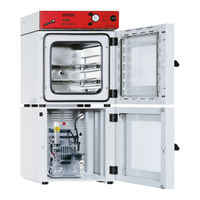
Vacuum Module for Vacuum Drying Ovens
Brand:
binder
| Category:
Oven
| Size: 1.46 MB
Table of Contents
Deutsch
2
1 Sicherheitshinweise
2
Table of Contents
2
2 Lieferumfang
3
Aufstellung
4
3 Montage des Vakuumtrockenschranks auf dem Vakuummodul
4
Montage des Verbindungsblechs
5
Schlauchanschluss am Vakuumtrockenschrank VD
6
Schlauchanschluss am Vakuumtrockenschrank VDL
6
4 Verlegen der Saugleitung
6
Befestigung des Schlauchs an der Gehäuserückwand
7
5 Kondensat-Auffangwanne
8
6 Herstellung des Potenzialausgleichs Beim VDL
9
Potenzialausgleich zwischen Kondensat-Auffangwanne und Vakuum-Modul
9
Potenzialausgleich zwischen VDL und Vakuummodul
9
Potenzialausgleich zwischen Vakuumpumpe und Vakuummodul
10
7 Anschluss einer Absaugung am Vakuummodul
11
Potenzialausgleich zwischen Vakuummodul und der Ableitfähigen Oberfläche am Aufstellungsort
11
English
12
1 Safety Instructions
12
2 Scope of Delivery
13
Installation
14
3 Mounting the Vacuum Drying Oven on the Vacuum Module
14
Mounting the Connecting Plate
15
Hose Connection at the Vacuum Drying Oven VD
16
Hose Connection at the Vacuum Drying Oven VDL
16
4 Installing the Suction Line
16
Fixing the Hose at the Housing Rear
17
5 Condensate Collecting Tray
18
6 Achieving Equipotential Bonding with VDL
19
Equipotential Bonding between the Condensate Collecting Tray and Vacuum Module
19
Equipotential Bonding between the VDL and Vacuum Module
19
Equipotential Bonding between the Vacuum Pump and the Vacuum Module
20
7 Connection of a Suction System at the Vacuum Module
21
Equipotential Bonding between the Vacuum Module and the Conductive Surface of the Installation Site
21
Français
22
1 Consignes de Sécurité
22
2 Etendue de Livraison
23
Installation
24
3 Montage de L'étuve de Séchage À Vide Sur Le Module de Vide
24
Montage de la Plaque de Raccord
25
Connexion du Tube À L'étuve de Séchage À Vide VD
26
Connexion du Tube À L'étuve de Séchage À Vide VDL
26
4 Disposition du Conduit D'aspiration
26
Fixation du Tube À la Face Arrière du Boîtier
27
5 Bac de Rétention de Condensat
28
6 Création de la Liaison Équipotentielle Chez la VDL
29
Liaison Équipotentielle entre la VDL Et Le Module de Vide
29
Liaison Équipotentielle entre Le Bac de Rétention de Condensat Et Le Module de Vide
29
Liaison Équipotentielle entre la Pompe À Vide Et Le Module de Vide
30
Liaison Équipotentielle entre Le Module de Vide Et la Surface Conductrice Au Lieu D'installation
31
7 Raccordement D'une Aspiration Au Module de Vide
31
Advertisement
Related Products
Binder vdl 115
Binder vdl 53
binder VDL Series
Binder VDL 23-UL
Binder VDL 56
Binder VDL 56-UL
Binder VDL 115-UL
Binder VD 23
Binder VD 115-UL
Binder VD 53-UL
Binder Categories
Laboratory Equipment
Accessories
Climate chamber
Oven
Media Converter
More Binder Manuals
Login
Sign In
OR
Sign in with Facebook
Sign in with Google
Upload manual
Upload from disk
Upload from URL