Sign In
Upload
Manuals
Brands
Binder Manuals
Laboratory Equipment
VD 23
Binder VD 23 Manuals
Manuals and User Guides for Binder VD 23. We have
4
Binder VD 23 manuals available for free PDF download: Operating Manual, Mounting Instructions
Binder VD 23 Operating Manual (173 pages)
Vacuum Drying Oven
Brand:
Binder
| Category:
Oven
| Size: 7.22 MB
Table of Contents
Table of Contents
2
1 Safety
8
Personnel Qualification
8
Operating Manual
8
Legal Considerations
8
Structure of the Safety Instructions
9
Signal Word Panel
9
Safety Alert Symbol
9
Pictograms
10
Word Message Panel Structure
10
Localization / Position of Safety Labels on the Chamber
11
Type Plate
11
General Safety Instructions on Installing and Operating the Chamber
12
Intended Use
14
Foreseeable Misuse
15
Residual Risks
16
Operating Instructions
17
Measures to Prevent Accidents
17
2 Description of the Equipment
19
Chamber Overview
20
Instrument Panel with Regular RD4 Controller
21
Instrument Panel with Optional MB2 Controller
21
Connections on the Rear of the Chamber
21
3 Completeness of Delivery, Transportation, Storage, and Installation
23
Unpacking, and Checking Equipment and Completeness of Delivery
23
Guidelines for Safe Lifting and Transportation
24
Storage
24
Location of Installation and Ambient Conditions
24
4 Installation and Connections
26
Vacuum Expansion Racks and Rack Holders
26
Pump Module (Option)
27
Pump Module Without Pump (Option)
28
Pump Module with Pump Stand (Option)
28
Vacuum Connection
30
VD Connection Kit (Option)
30
Connecting Inert Gas Supply
31
Electrical Connection
32
5 Functional Overview and Menu Structure of the Controller
33
RD4 Controller
33
Menu Structure of the Controller and Access Levels
34
MB2 Controller
35
Operating Functions in Normal Display
36
Display Views: Normal Display, Program Display, Chart-Recorder Display
37
MB2 Controller Icons Overview
38
MB2 Controller Operating Modes
40
MB2 Controller Menu Structure
40
Main Menu
41
Settings" Submenu
42
Service" Submenu
42
Principle of Controller Entries
43
Performance During and after Power Failures
43
RD4 Controller
43
MB2 Controller
44
6 Start up
44
Condition after Establishing the Power Connection
44
Standby Mode Turning on and off the Vacuum Drying Oven
45
RD4 Controller
45
MB2 Controller
45
Controller Settings Upon Start up
46
RD4 Controller
46
MB2 Controller
46
Vacuum System
47
Evacuation
47
Ventilation after Completing the Drying Procedure (Flooding with Ambient Air or Inert Gas)
48
Ventilation / Breaking the Vacuum in Case of a Power Failure
48
Operation with Inert Gas
48
7 Set-Point Entry
49
RD4 Controller
49
Temperature Set-Point Entry
49
Pressure Set-Point Entry
50
MB2 Controller
50
Set-Point Entry through the "Setpoints" Menu
50
Direct Setpoint Entry Via Normal Display
51
8 Setting Special Controller Functions
52
Menu Structure
52
RD4 Controller
52
Functions On/Off" Menu
52
Quick Access Menu
53
MB2 Controller
53
Functions On/Off" Menu
53
Control On/Off" Menu
55
Turning off the Vacuum Pump Via the Socket on the Pump Module
55
RD4 Controller
55
MB2 Controller
56
Using the Optional Connection "GAS/AIR 2" for Ventilation
56
RD4 Controller
57
MB2 Controller
57
Close All Valves
58
RD4 Controller
58
MB2 Controller
58
Activating / Deactivating Temperature Control
59
RD4 Controller
59
MB2 Controller
59
Activating / Deactivating Pressure Control
60
RD4 Controller
60
MB2 Controller
61
Drying Monitoring
62
RD4 Controller
63
MB2 Controller
63
9 Authorization Levels and Password Protection
64
RD4 Controller
64
Password Request
64
Assign and Modify a Password
64
Assign and Modify the User Password
64
Assign and Modify the Admin Password
65
MB2 Controller
66
User Management, Authorization Levels and Password Protection
66
Log in
69
Log out
70
User Change
70
Password Assignment and Password Change
71
Password Change
71
Deleting the Password for an Individual Authorization Level
73
New Password Assignment for "Service" or "Admin" Authorization Level When the Password Function was Deactivated
74
Activation Code
75
10 General Controller Settings and Information
76
RD4 Controller
76
Selecting the Controller's Menu Language
76
Selecting the Temperature Unit
76
Setting the Current Date
77
Setting the Current Time
78
Function "Language Selection at Restart
78
Setting the Chamber Address
79
Display Brightness
79
Display of the Inner Chamber Temperature and the Heating Temperature
79
MB2 Controller
80
Selecting the Controller's Menu Language
80
Setting Date and Time
80
Selecting the Temperature Unit
82
Display Configuration
82
Adapting the Display Parameters
82
Touchscreen Calibration
83
Event List
84
Service Contact Page
84
Current Operating Parameters
85
Technical Chamber Information
85
11 Temperature Safety Devices
86
Over Temperature Protective Device Class 2 (Thermal Switch)
86
Overtemperature Safety Controller Class 2
86
Safety Controller Mode
86
Setting the Safety Controller
87
RD4 Controller: Setting the Safety Controller Mode
87
RD4 Controller: Setting the Safety Controller Value
87
MB2 Controller
88
Message and Measures in the State of Alarm
89
RD4 Controller
89
MB2 Controller
89
Function Check
90
12 Tolerance Range Settings
90
RD4 Controller
90
Setting the Delay Time for Temperature Tolerance Range Alarm
90
Setting the Temperature Tolerance Range
90
Setting the Delay Time for Pressure Tolerance Range Alarm
91
Setting the Pressure Tolerance Range
91
State of Alarm
91
MB2 Controller
92
Setting the Alarm Delay Times and the Tolerance Ranges
92
Alarm Condition
92
13 Notification and Alarm Functions
93
Information Messages
93
RD4 Controller
93
MB2 Controller
94
Alarm Messages
95
RD4 Controller
95
MB2 Controller
96
Resetting an Alarm
97
RD4 Controller
97
MB2 Controller
97
Activating / Deactivating the Audible Alarm (Buzzer)
98
RD4 Controller
98
MB2 Controller
98
14 Mb2 Controller: Timer Program (Stopwatch Function)
99
Starting a Timer Program
99
Performance During Program Delay Time
99
Stopping a Running Timer Program
100
Pausing a Running Timer Program
100
Cancelling a Running Timer Program
100
Performance after the End of the Program
100
15 Mb2 Controller: Time Programs
101
Starting an Existing Time Program
101
Performance During Program Delay Time
102
Stopping a Running Time Program
102
Pausing a Running Time Program
102
Cancelling a Running Time Program
102
Performance after the End of the Program
102
Creating a New Time Program
103
Program Editor: Program Management
103
Deleting a Time Program
104
Section Editor: Section Management
105
Add a New Program Section
106
Copy and Insert or Replace a Program Section
106
Deleting a Program Section
107
Value Entry for a Program Section
108
Section Duration
108
Set-Point Ramp and Set-Point Step
109
Special Controller Functions
110
Setpoint Entry
111
Tolerance Range
111
Repeating One or Several Sections Within a Time Program
112
Saving the Time Program
113
16 Mb2 Controller: Week Programs
114
Starting an Existing Week Program
114
Cancelling a Running Week Program
114
Creating a New Week Program
115
Program Editor: Program Management
116
Deleting a Week Program
117
Section Editor: Section Management
118
Add a New Program Section
119
Copy and Insert or Replace a Program Section
119
Deleting a Program Section
120
Value Entry for a Program Section in the Section View
120
Set-Point Ramp and Set-Point Step Modes
120
Weekday
121
Start Time
121
Setpoint Entry
121
Special Controller Functions
122
17 Network and Communication
122
RD4 Controller: Ethernet Network Settings
122
Showing the Network Settings
122
Showing the Chamber's MAC Address
122
Showing the IP Address
123
Showing the Subnet Mask
123
Showing the Standard Gateway
123
Showing the DNS Server Address
124
Showing the DNS Chamber Name
124
Changing the Configuration of the Network Settings
124
Selecting the Type of IP Address Assignment (Automatic / Manual)
125
Selecting the Type of Assignment of the DNS Server Address (Automatic / Manual)
125
Assigning the IP Address
125
Setting the Subnet Mask
126
Setting the Standard Gateway
127
Assigning the DNS Server Address
127
MB2 Controller
128
Ethernet
128
Configuration
128
Display of MAC Address
129
Web Server
129
E-Mail
130
18 Rd4 Controller: Data Recorder
131
Recorded Data
131
Storage Capacity
131
Setting the Storage Rate for the "DL1" Recorder Data
132
Deleting the Data Recorder
132
19 Usb Menu: Data Transfer Via Usb Interface
132
RD4 Controller
132
Connecting the USB Stick
133
Import Function
133
Export Functions
133
Ongoing Data Transfer
134
Error During Data Transmission
134
Removing the USB Stick
134
MB2 Controller
134
20 Mb2 Controller: Chart Recorder Display
136
Views
136
Show and Hide Legend
136
History Display
136
Setting the Parameters
139
21 Reference Measurements
140
Checking the Temperature in the Inner Chamber
140
Checking the Controller Display
140
Checking the Spatial Temperature Exactitude
140
22 Options
141
APT-COM™ 4 Multi Management Software (Option)
141
Analog Outputs for Temperature and Pressure (Option)
141
Measuring Access Port for Vacuum, 9 Poles (Option)
141
Object Temperature Display with Flexible Pt 100 Temperature Sensor (Option)
142
Connection of the Object Temperature Sensor
142
Display on the RD4 Controller
143
Display on the MB2 Controller
143
LED Interior Lighting
143
23 Cleaning and Decontamination
144
Cleaning
144
Decontamination / Chemical Disinfection
145
24 Maintenance and Service, Troubleshooting, Repair, Testing
147
General Information, Personnel Qualification
147
Simple Troubleshooting
147
Maintenance Intervals, Service
150
Service Reminder
150
RD4 Controller
150
MB2 Controller
151
Sending the Chamber Back to BINDER Gmbh
151
25 Disposal
152
Disposal of the Transport Packing
152
Decommissioning
152
Disposal of the Chamber in the Federal Republic of Germany
153
Disposal of the Chamber in the Member States of the EU Except for the Federal Republic of Germany
154
Disposal of the Chamber in Non-Member States of the EU
155
26 Technical Description
156
Factory Calibration and Adjustment
156
Over Current Protection
156
VD / VD-UL Technical Data
156
Equipment and Options (Extract)
158
Accessories and Spare Parts (Extract)
159
Dimensions
161
27 Certificates and Declarations of Conformity
164
EU Declaration of Conformity
164
28 Product Registration
167
29 Contamination Clearance Certificate
168
For Chambers Located Outside USA and Canada
168
For Chambers Located in USA and Canada
171
Advertisement
Binder VD 23 Operating Manual (97 pages)
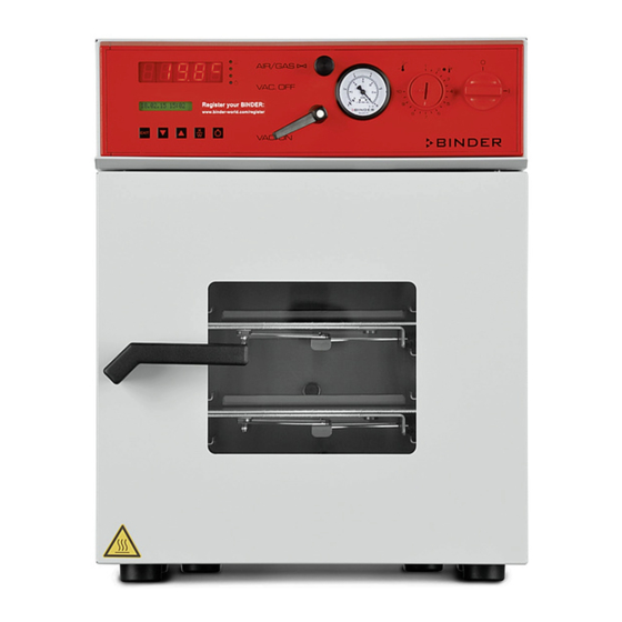
VD (E2.1) Vacuum drying oven Model version: VD023-230V; VD023UL-120V; VD053-230V; VD053UL-120V; VD115-230V; VD115UL-120V
Brand:
Binder
| Category:
Laboratory Equipment
| Size: 5.64 MB
Table of Contents
Table of Contents
2
1 Safety
5
Legal Considerations
5
Structure of the Safety Instructions
5
Signal Word Panel
5
Safety Alert Symbol
6
Pictograms
6
Word Message Panel Structure
7
Localization / Position of Safety Labels on the Chamber
7
Type Plate
8
General Safety Instructions on Installing and Operating the Chamber
9
Intended Use
11
2 Description of the Equipment
12
Chamber Overview
13
VD 23 Control Panel
14
VD 53 / 115 Control Panel
14
Connections at the Rear of the Chamber
15
3 Completeness of Delivery, Transportation, Storage, and Installation
16
Unpacking, and Checking Equipment and Completeness of Delivery
16
Guidelines for Safe Lifting and Transportation
17
Storage
17
Location of Installation and Ambient Conditions
17
4 Installation and Connections
19
Vacuum Expansion Racks
19
Vacuum Connection
19
Inert Gas Connection
19
Electrical Connection
20
5 Start up
21
Settings at the RD3 Program Controller
21
General Indications on the RD3 Program Controller
22
6 Fixed Value Entry Mode
24
7 Week Program Editor
25
Program Table Template for Week Program Editor
27
Programming Example of the Week Program Editor
28
Desired Time Function
28
Proceeding Overview
28
Proceeding in Detail
29
8 Program Editor
34
Selecting between Set-Point Ramp and Set-Point Step
34
Programming with Setting "Ramp" (Default Setting)
34
Programming with Setting "Step
36
General Notes on Programming Temperature Transitions
37
Set-Point Entry for Program Operation
37
Program Table Template
40
Deleting a Program Section
41
9 Program Start Level
42
10 User Level
45
11 Performance in Case of Failures
51
Performance after Power Failure
51
Alarm Messages
51
12 Temperature Safety Device Class 2
51
13 Reference Measurements. Checking the Temperature in the Inner Chamber
53
14 Commissioning the Vacuum
53
Evacuation
54
Breaking the Vacuum (Flooding with Ambient Air)
54
Operation with Inert Gas
55
15 Switching Contacts 24V DC Via Operation Lines
56
16 Options
57
Connection Kit VD (Option)
57
Vacuum Module Empty (Without Pump) (Option)
57
Vacuum Module with Chemical Membrane Pump VP 1.1 or VP 2.1 (Option)
59
Vacuum Module with Speed Controlled Chemical Membrane Pump VP 3.1 and Vacuum Controller (Option)
61
Digital Pressure Display (Option)
63
Additional Measuring Channel for Digital Object Temperature Display with Flexible Pt 100 Temperature Sensor (Option)
63
Measuring Access Port Vacuum 9 Poles (Option)
64
Communication Software APT-COM™ 3 Datacontrolsystem (Option)
65
17 Maintenance, Cleaning, and Service
65
Maintenance Intervals, Service
65
Cleaning and Decontamination
66
Cleaning
66
Decontamination
67
Sending the Chamber Back to BINDER Gmbh
69
18 Disposal
69
Disposal of the Transport Packing
69
Decommissioning
70
Disposal of the Chamber in the Federal Republic of Germany
70
Disposal of the Chamber in the Member States of the EU Except for the Federal Republic of Germany
71
Disposal of the Chamber in Non-Member States of the EU
73
19 Troubleshooting
73
20 Technical Description
75
Factory Calibration and Adjustment
75
Technical Data
75
Equipment and Options (Extract)
77
Accessories and Spare Parts (Extract)
78
Dimensions VD 23
80
Dimensions VD 53
81
Dimensions VD 115
82
21 Certificates and Declarations of Conformity
83
EU Declaration of Conformity
83
Certificate for the GS Mark of Conformity of the "VDE Prüf- und Zertifizierungsinstitut" (Testing and Certification Institute of the Association for Electrical, Electronic and Information Technologies)
85
22 Product Registration
90
23 Contamination Clearance Certificate
91
For Chambers Located Outside USA and Canada
91
For Chambers Located in USA and Canada
94
Binder VD 23 Operating Manual (83 pages)
Vacuum Drying Ovens with microprocessor program controller RD3
Brand:
Binder
| Category:
Oven
| Size: 2.94 MB
Table of Contents
EC - Declaration of Conformity
2
Product Registration
5
Table of Contents
6
Safety
8
Legal Considerations
8
Structure of the Safety Instructions
8
Signal Word Panel
8
Safety Alert Symbol
9
Pictograms
9
Word Message Panel Structure
10
Localization / Position of Safety Labels on the Unit
10
Type Plate
11
General Safety Instructions on Installing and Operating the Vacuum Drying Oven
12
Intended Use
14
Description of the Equipment
14
Overview of the Equipment
15
VD 23 Control Panel
16
VD 53 / 115 Control Panel
16
Connections at the Rear of the Unit
17
Completeness of Delivery, Transportation, Storage, and Installation
18
Unpacking, and Checking Equipment and Completeness of Delivery
18
Guidelines for Safe Lifting and Transportation
19
Storage
19
Location of Installation and Ambient Conditions
19
Installation and Connections
20
Vacuum Expansion Racks
20
Electrical Connection
21
Vacuum Connection
21
Inert Gas Connection
22
Start up
22
Settings at the RD3 Program Controller
22
General Indications
24
Fixed Value Entry Mode
25
Week Program Editor
26
Program Table Template for Week Program Editor
28
Programming Example of the Week Program Editor
29
Desired Time Function
29
Proceeding Overview
29
Proceeding in Detail
30
Program Editor
35
Selecting between Set-Point Ramp and Set-Point Step
35
Programming with Setting "Ramp" (Default Setting)
35
Programming with Setting "Step
37
General Notes on Programming Temperature Transitions
38
Set-Point Entry for Program Operation
38
Program Table Template
41
Deleting a Program Section
42
Program Start Level
43
User Level
46
Performance in Case of Failures
52
Performance after Power Failure
52
Alarm Messages
52
Safety Device Class 2 (Din 12880)
52
Reference Measurements. Checking the Temperature in the Inner Chamber
53
Commissioning the Vacuum
54
Evacuation
54
Breaking the Vacuum (Flooding)
55
Operation with Inert Gas
55
Switching Contacts 24V DC Via Operation Lines
55
Options
57
Connection Kit VD (Option)
57
Vacuum Module Empty (Without Pump) (Option)
57
Vacuum Module with Chemical Membrane Pump VP 1.1 or VP 2.1 (Option)
59
Vacuum Module with Speed Controlled Chemical Membrane Pump VP 3.1 and Vacuum Controller (Option)
61
Digital Pressure Display (Option)
63
Additional Measuring Channel for Digital Object Temperature Display with Flexible Pt 100 Temperature Sensor (Option)
63
Measuring Access Port Vacuum 9 Poles (Option)
64
Communication Software APT-COM™ 3 Datacontrolsystem (Option)
65
Protocol Printer (Available Via BINDER INDIVIDUAL Customized Solutions)
65
Maintenance, Cleaning, and Service
66
Maintenance Intervals, Service
66
Cleaning and Decontamination
66
Sending the Unit Back to BINDER Gmbh
67
Disposal
68
Disposal of the Transport Packing
68
Decommissioning
68
Disposal of the Unit in the Federal Republic of Germany
69
Disposal of the Unit in the Member States of the EC Except for the Federal Republic of Germany
70
Disposal of the Unit in Non-Member States of the EC
71
Troubleshooting
72
Technical Description
73
Factory Calibration and Adjustment
73
VD Technical Data
74
Equipment and Options
75
Spare Parts
77
Dimensions VD 23
78
Dimensions VD 53
79
Dimensions VD 115
80
Contamination Clearance Certificate
81
Advertisement
binder VD 23 Mounting Instructions (32 pages)
Vacuum Module for Vacuum Drying Ovens
Brand:
binder
| Category:
Oven
| Size: 1.46 MB
Table of Contents
Deutsch
2
1 Sicherheitshinweise
2
Table of Contents
2
2 Lieferumfang
3
Aufstellung
4
3 Montage des Vakuumtrockenschranks auf dem Vakuummodul
4
Montage des Verbindungsblechs
5
Schlauchanschluss am Vakuumtrockenschrank VD
6
Schlauchanschluss am Vakuumtrockenschrank VDL
6
4 Verlegen der Saugleitung
6
Befestigung des Schlauchs an der Gehäuserückwand
7
5 Kondensat-Auffangwanne
8
6 Herstellung des Potenzialausgleichs Beim VDL
9
Potenzialausgleich zwischen Kondensat-Auffangwanne und Vakuum-Modul
9
Potenzialausgleich zwischen VDL und Vakuummodul
9
Potenzialausgleich zwischen Vakuumpumpe und Vakuummodul
10
7 Anschluss einer Absaugung am Vakuummodul
11
Potenzialausgleich zwischen Vakuummodul und der Ableitfähigen Oberfläche am Aufstellungsort
11
English
12
1 Safety Instructions
12
2 Scope of Delivery
13
Installation
14
3 Mounting the Vacuum Drying Oven on the Vacuum Module
14
Mounting the Connecting Plate
15
Hose Connection at the Vacuum Drying Oven VD
16
Hose Connection at the Vacuum Drying Oven VDL
16
4 Installing the Suction Line
16
Fixing the Hose at the Housing Rear
17
5 Condensate Collecting Tray
18
6 Achieving Equipotential Bonding with VDL
19
Equipotential Bonding between the Condensate Collecting Tray and Vacuum Module
19
Equipotential Bonding between the VDL and Vacuum Module
19
Equipotential Bonding between the Vacuum Pump and the Vacuum Module
20
7 Connection of a Suction System at the Vacuum Module
21
Equipotential Bonding between the Vacuum Module and the Conductive Surface of the Installation Site
21
Français
22
1 Consignes de Sécurité
22
2 Etendue de Livraison
23
Installation
24
3 Montage de L'étuve de Séchage À Vide Sur Le Module de Vide
24
Montage de la Plaque de Raccord
25
Connexion du Tube À L'étuve de Séchage À Vide VD
26
Connexion du Tube À L'étuve de Séchage À Vide VDL
26
4 Disposition du Conduit D'aspiration
26
Fixation du Tube À la Face Arrière du Boîtier
27
5 Bac de Rétention de Condensat
28
6 Création de la Liaison Équipotentielle Chez la VDL
29
Liaison Équipotentielle entre la VDL Et Le Module de Vide
29
Liaison Équipotentielle entre Le Bac de Rétention de Condensat Et Le Module de Vide
29
Liaison Équipotentielle entre la Pompe À Vide Et Le Module de Vide
30
Liaison Équipotentielle entre Le Module de Vide Et la Surface Conductrice Au Lieu D'installation
31
7 Raccordement D'une Aspiration Au Module de Vide
31
Advertisement
Related Products
Binder VD 23-UL
Binder VD 115-UL
Binder VD 53
Binder VD 53-UL
Binder VD 115
Binder vdl 53
binder VDL Series
Binder VDL 23-UL
Binder VDL 56-UL
Binder VD 56
Binder Categories
Laboratory Equipment
Climate chamber
Accessories
Oven
Media Converter
More Binder Manuals
Login
Sign In
OR
Sign in with Facebook
Sign in with Google
Upload manual
Upload from disk
Upload from URL