Binder vdl 23 Operating Manual
Vacuum drying ovens for flammable solvents
Hide thumbs
Also See for vdl 23:
- Mounting instructions (32 pages) ,
- Operating manual (235 pages) ,
- Operating manual (207 pages)
Table of Contents
Advertisement
Operating Manual
VDL (E2.1)
Vacuum drying ovens
for flammable solvents
with microprocessor program controller RD3
Model
Model version
VDL 23
VDL023-230V
VDL 53
VDL053-230V
VDL 115
VDL115-230V
BINDER GmbH
Address
Tel.
Fax
Internet
E-mail
Service Hotline
Service Fax
Service E-Mail
Service Hotline USA
Service Hotline Asia Pacific
Service Hotline Russia and CIS +7 495 98815 16
Issue 05/2016
Art. No.
9030-0038, 9130-0038
9030-0039, 9130-0039
9030-0040, 9130-0040
Post office box 102
D-78502 Tuttlingen
+49 7462 2005 0
+49 7462 2005 100
http://www.binder-world.com
info@binder-world.com
+49 7462 2005 555
+49 7462 2005 93 555
service@binder-world.com
+1 866 885 9794 or +1 631 224 4340 x3
+852 390 705 04 or +852 390 705 03
Art. No. 7001-0124
Advertisement
Table of Contents

Subscribe to Our Youtube Channel
Related Manuals for Binder vdl 23


Summary of Contents for Binder vdl 23
- Page 1 Operating Manual VDL (E2.1) Vacuum drying ovens for flammable solvents with microprocessor program controller RD3 Model Model version Art. No. VDL 23 VDL023-230V 9030-0038, 9130-0038 VDL 53 VDL053-230V 9030-0039, 9130-0039 VDL 115 VDL115-230V 9030-0040, 9130-0040 BINDER GmbH Address Post office box 102 D-78502 Tuttlingen Tel.
-
Page 2: Table Of Contents
Contents SAFETY ........................5 Legal considerations ........................... 5 Structure of the safety instructions ...................... 5 1.2.1 Signal word panel ........................5 1.2.2 Safety alert symbol ........................6 1.2.3 Pictograms ..........................6 1.2.4 Word message panel structure ....................7 Localization / position of safety labels on the chamber ..............7 Type plate ............................ - Page 3 16.2.1 Cleaning ..........................82 16.2.2 Decontamination ........................83 16.3 Sending the chamber back to BINDER GmbH ................. 85 17. DISPOSAL......................85 17.1 Disposal of the transport packing ..................... 85 17.2 Decommissioning ..........................86 17.3 Disposal of the chamber in the Federal Republic of Germany ............86 17.4 Disposal of the chamber in the member states of the EC except for the Federal Republic of...
- Page 4 19.3 Equipment and options (extract) ....................... 93 19.4 Accessories and spare parts (extract) ....................94 19.5 Dimensions VDL 23 .......................... 95 19.6 Dimensions VDL 53 .......................... 96 19.7 Dimensions VDL 115 ........................97 20. CERTIFICATES AND DECLARATIONS OF CONFORMITY ....... 98 20.1 EU Declaration of Conformity ......................
-
Page 5: Safety
Understanding and observing the instructions in this operating manual are prerequisites for hazard-free use and safety during operation and maintenance. In no event shall BINDER be held liable for any dam- ages, direct or incidental arising out of or related to the use of this manual. -
Page 6: Safety Alert Symbol
DANGER Indicates an imminently hazardous situation that, if not avoided, will result in death or serious (irreversi- ble) injury. WARNING Indicates a potentially hazardous situation which, if not avoided, could result in death or serious (irre- versible) injury. CAUTION Indicates a potentially hazardous situation which, if not avoided, may result in moderate or minor (re- versible) injury. -
Page 7: Word Message Panel Structure
Mandatory action signs Lift with several persons Mandatory regulation Read operating Disconnect the power instructions plug Environment protection Wear eye protectors Wear protective gloves Prohibition signs Do NOT touch Do NOT spray with water Information to be observed in order to ensure optimum function of the product. 1.2.4 Word message panel structure Type / cause of hazard. -
Page 8: Type Plate
Figure 1: Position of labels on the chamber Keep safety labels complete and legible. Replace safety labels that are no longer legible. Contact BINDER Service for these replacements. Type plate Position of type plate: left chamber side (seen from front), at the bottom right-hand. -
Page 9: General Safety Instructions On Installing And Operating The Vacuum Drying Oven
ZH 1/119, issued by the employers’ liability insurance association) (for Germany). BINDER GmbH is only responsible for the safety features of the chamber provided skilled electricians or qualified personnel authorized by BINDER perform all maintenance and repair, and if components relat- ing to chamber safety are replaced in the event of failure with original spare parts. -
Page 10: Safety Instructions On Installation And Ambient Conditions
1.5.1 Safety instructions on installation and ambient conditions Familiarize yourself with the local conditions, particularly allocation to a defined potentially explosive area (zones) and the relevant technical safety requirements. During installation, commissioning and operation of the vacuum drying oven and the connected vacuum pump or in-house vacuum supply, always follow the requirements defined by the installation site. -
Page 11: Safety Instructions On Vacuum Supply
Otherwise, use flame arresters (flame flash-through barrier). For in- stalling a flame arrester, please contact the BINDER INDIVIDUAL team. In case of an explosion, the flame can be suctioned into an in-house vacuum system thereby resulting in further explosions. -
Page 12: Safety Instructions On The Charging Material
The ATEX Directive 2014/34/EU compliant vacuum pumps offered by BINDER are designed for a gas inlet temperature of 40 °C / 104°F max. Do NOT exceed this temperature. If the gas inlet temperature is too high and then becomes even warmer by compression in the pump, the resulting temperature (of the gas-solvent mixture inside the pump) could exceed the solvent’s temperature class and ignition tempera-... - Page 13 If the ignition temperature of a solvent contained in the drying material is exceeded during the drying pro- cess, there is an immediate risk of fire and explosion. DANGER Formation of explosive solvent-air mixtures. Fire and explosion hazard. Danger of death. ∅...
-
Page 14: Safety Instructions On Operating The Vacuum Drying Oven
1.5.4 Safety instructions on operating the vacuum drying oven Note the following points before starting up the oven: • When loading the chamber and possibly at the moment of removal, also in the context of intended use, an explosive mixture may form in the working space. Define a safety area of at least 1m from the chamber front and ensure ventilation / venting. - Page 15 During operation with inert gas, the chamber is supplied with an oxygen displacing gas (e.g. N ). Inert gases in high concentrations are hazardous to health. They are colorless and almost odorless and there- fore practically imperceptible. Inhalation of inert gases can cause drowsiness up to respiratory arrest. When the O content of the air decreases below 18%, there is risk of death from lack of oxygen.
- Page 16 Measures required for operation with solvent-containing materials that can form an explosive mixture with air: • Only trained personnel with key-authorization can work on the VDL vacuum drying oven • Sweep the area for electrical equipment with compressed air or inert gas for at least 15 minutes.
-
Page 17: Intended Use
Such ingredients include in particu- lar acids and halides. Any corrosive damage caused by such ingredients is excluded from liability by BINDER GmbH. 1.6.1 Operation log For safety reasons, keep an operation log. - Page 18 Operation log for the VDL vacuum drying oven Serial number..........Max. tempera- Ignition tem- Set drying tem- Solvent ture of safety Date Signature perature perature device VDL (E2.1) 05/2016 page 18/108...
-
Page 19: Description Of The Equipment
Description of the equipment The VDL vacuum drying oven has been inspected by the TÜV Product Service GmbH in accordance with all safety-relevant guidelines and bears the TÜV-Mark P mark. Consequently, it is also expressly ap- proved for drying materials with unlimited quantities of organic solvents. The regular model is equipped with an explosion proof inner chamber. -
Page 20: Safety Equipment
Safety equipment • Pressure control device The VDL vacuum drying oven is equipped with a pressure control device with atmospheric pressure compensation and has a set switch point of 125 ± 25 mbar / 3.69 ± 0.74 inHg). In the event of mal- function, some procedures would become an ignition source. -
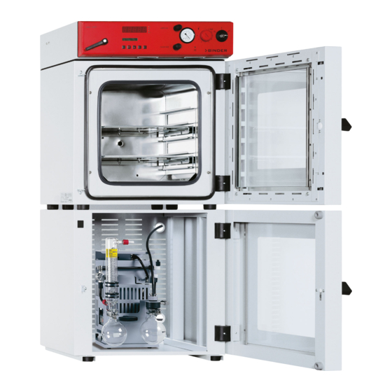
Page 21: Overview Of The Oven
Overview of the oven Figure 4: VDL 53 Area for electrical equipment swept with compressed air, and control panel Compressed air connection Information panel “Temperature setting” Information panel short description Spring-mounted safety glass window Chamber door VDL (E2.1) 05/2016 page 21/108... -
Page 22: Vdl Control Panel
VDL control panel (6) (5) (2a) Figure 5: VDL 23 control panel (6) (5) (2) (2a) VAC.OFF VAC.ON Figure 6: VDL 53/115 control panel Key switch (main power switch) Temperature safety device class 2 (2a) Red alarm lamp of the safety device class 2... -
Page 23: Connections At The Rear Of The Chamber
(13) Vacuum connection with small flange DN16 VAC.ON (14) DIN socket “Object-Pt100“ (option) to connect a Pt 100 sensor (with option “object temperature display”) Figure 8: Connections left side VDL 23 (15) Measuring connection with small flange DN16 VDL (E2.1) 05/2016 page 23/108... -
Page 24: Temperature Setting" Information Panel (Ignition Temperature Vs. Drying Temperature)
“Temperature setting” information panel (ignition temperature vs. drying temperature) Temperatureinstellung VDL Adjustment of temperature VDL This information panel is mounted to Ajustement de température VDL the door of the VDL vacuum drying oven and shows the maximum per- missible drying temperature depend- ing on the ignition temperature of the solvent. -
Page 25: Overview Of The Zone Classification Of The Ovens
• Let the oven cool down to ambient temperature before you start a new drying process with a modified ignition temperature. Overview of the zone classification of the ovens Figure 10: Zone classification VDL 23 VDL (E2.1) 05/2016 page 25/108... - Page 26 Figure 11: Zone classification VDL 53 and 115 VDL (E2.1) 05/2016 page 26/108...
-
Page 27: Completeness Of Delivery, Transportation, Storage, And Installation
Note on second-hand chambers (Ex-Demo-Units): Second-hand chambers are chambers that have been used for a short time for tests or exhibitions. They are thoroughly tested before resale. BINDER ensures that the chamber is technically sound and will work flawlessly. Second-hand chambers are marked with a sticker on the chamber door. Please remove the sticker be- fore commissioning the chamber. -
Page 28: Guidelines For Safe Lifting And Transportation
Lift chambers size 115 with the aid of 6 people. • Permissible ambient temperature range during transport: -10 °C / 14°F to +60 °C / 140°F. You can order transport packing for moving or shipping purposes from BINDER Service. Storage Intermediate storage of the chamber is possible in a closed and dry room. - Page 29 (chap. 15.3). During operation a fire extinguisher must be available. The maximum permissible ambient temperature of the vacuum pumps delivered by BINDER is 40 °C / 104°F.
-
Page 30: Installation And Connections
WARNING High concentration of inert gas. Risk of death by suffocation. ∅ Do NOT set up chambers in non-ventilated recesses. Ensure technical ventilation measures. Respect the relevant regulations for handling these gases. When decommissioning the vacuum drying oven, shut off the inert gas supply: Close valve (6). -
Page 31: Vacuum Connection
(13) with small flange DN16 must be connected to the back of the chamber at the top with the vacuum pump or domestic vacuum system via a vacuum suction hose. For connecting to the chamber, BINDER recommends the connection kits VP4 (Art. no. 8012-0621) or VP5 (Art. no. 8012-0622), (chap. 15.1). - Page 32 The ATEX Directive 2014/34/EU compliant vacuum pumps offered by BINDER are designed for a gas inlet temperature of 40 °C / 104°F max. Do NOT exceed this temperature. If the gas inlet tempera- ture is too high and then becomes even warmer by compression in the pump, the resulting temperature (of the gas-solvent mixture inside the pump) could exceed the solvent’s temperature class and ignition...
-
Page 33: Notes Regarding Use Of Vacuum Pumps Of Other Manufacturers
4.2.1 Notes regarding use of vacuum pumps of other manufacturers Connection to a vacuum source Connect the vacuum connection (13) (small flange DN 16) at the back of the chamber at the top to a vac- uum pump or domestic vacuum system via a vacuum conduit or fixed vacuum tubing. Within the European Union, units that will be operated in potentially explosive areas have to meet the requirements of ATEX Directive 2014/34/EU. -
Page 34: Compressed Air / Inert Gas Connection For Sweeping The Area For Electrical Equipment
The compressed air connection is preset at the factory. Do NOT change the setting. In deliv- ery condition of the oven, this setting is protected by a cover with seal. If the seal is broken, please inform BINDER Service to have the setting checked and to rein- stall the cover with seal. -
Page 35: Electrical Connection
Notes when using inert gas: When operating the VDL vacuum drying oven with inert gas, correctly follow the technical ventilation measures, as described in the DGUV guidelines 213-850 on safe working in laboratories (formerly BGI/GUV-I 850-0, BGR/GUV-R 120 or ZH 1/119, issued by the employers’ liability insurance association) (for Germany). -
Page 36: Start Up
Start up DANGER Solvent-containing air penetrating and concentration in the electrical area of the chamber. Explosion hazard. Before turning on the chamber via the key switch (1), sweep the area for electrical equipment at least 15 minutes with compressed air or inert gas. Sweeping the area for electrical equipment must take place during the entire operation, as otherwise the VDL vacuum drying oven will shut off at all poles. -
Page 37: General Indications
(setting in the user level, chap. 10). This setting is then valid for all program sections. Programming can be done directly through the keypad of the controller or graphically through the soft- ware APT-COM™ 3 DataControlSystem (option, chap. 15.6) specially developed by BINDER. General indications... - Page 38 Week program editor (chap.7) • Setting the shift points Do not use the week program timer when using explosive substances. Make sure in this case that the week program timer has been deactivated in the User Level (chap. 10). User level (chap. 10) •...
-
Page 39: Fixed Value Entry Mode
Fixed value entry mode Solvents and resulting vapors can ignite at excessive drying temperatures. DANGER Excess drying temperature. Ignition and explosion hazard. Determine the maximum drying temperature in relation to the ignition temperature of the solvent according to the information panel “Temperature setting” (chap. 2.5). Do NOT exceed this temperature when presetting the set point on the RD3 temperature controller. - Page 40 When changing the set-point, check the setting of the safety device (chap. 12). The values entered in fixed-value entry mode remain valid after program run-off and are then equilibrated. If the week program timer is active, depending on the running week program another set-point (SP2) may be targeted.
-
Page 41: Week Program Editor
Week program editor Do not use the week program timer when using explosive substances. Make sure in this case that the week program timer has been deactivated in the User Level (chap. 10). DANGER Exceeding the ignition temperature of a solvent after the program ends. Risk of fire and explosion. - Page 42 Press program key Display 1 shows 0000 Display 2 shows Shiftpt. (no function) Press program key Display 1 shows 0000 Display 2 shows (selection of the shift point) Shiftpt. (actual shift point: 1) Select the shift point (1 up to 4) with key Value is shown in display 2.
-
Page 43: Program Table Template For The Week Program Editor
Program table template for the Week Program Editor Program editor Program title Project Date: Day of the week Time Channel 1 Channel 2* (temperature) hh:mm ON = SP2 OFF = SP1 Monday Tuesday Wednesday Thursday Friday Saturday Sunday • Channel 2 is non-functional in the standard chamber VDL (E2.1) 05/2016 page 43/108... -
Page 44: Programming Example Of The Week Program Editor
Programming example of the Week program editor 7.2.1 Desired time function During the day (12 hours) the oven shall maintain a temperature of +80 °C / 176°F, and during the night (12 hours) it shall cool down / stop heating (set-point 30 °C / 86°F). This program shall automatically run during the whole year, i.e. -
Page 45: Proceeding In Detail
7.2.3 Proceeding in detail 1. Settings in the user level • Activating the week program timer • Checking and, if necessary, setting the real time clock Normal Display Display 1 shows e.g. 39.8 (actual temperature value) Display 2 shows (actual date and time, actual switching state of week pro- e.g. - Page 46 Display 1 shows e.g. 2006 (Actual setting: 2006) Display 2 shows Year 2006 (Setting the year of the real time clock) Set year (2006 up to 2050) using arrow Setting is shown in display 2. keys Press key Display 1 shows e.g.
- Page 47 Press key Display 1 shows 80.0 (actual temperature set-point 2) Display 2 shows SP2 TEMPERATURE (variable: temperature in °C) Enter temperature set-point 80 °C Value is shown in display 1. using arrow keys Press the EXIT button. The controller changes to Normal Display. 3.
- Page 48 Display 1 shows 06.00 (time of the selected shift point) (entry of time of the selected shift point) Display 2 shows Time 06:00 (actual setting: 6.00, i.e. 6 a.m.) Value is shown in display 2. Enter the time 06:00 using arrow keys Press key Display 1 shows 0000...
- Page 49 Display 1 shows 0000 Display 2 shows (selection of day of the week) Tuesday (actual selection: Tuesday) Select the next day of the week (Tuesday) Day of the week is shown in display 2. with key Press program key Display 1 shows 0000 Display 2 shows Shiftpt.
-
Page 50: Program Editor
Program editor Selecting between set-point ramp and set-point step You can program various kinds of temperature transitions. In the user level (chap. 10) you can select between the settings “Ramp” (default setting) and “Step”. Setting “Ramp” allows programming all kinds of temperature transitions. With setting “Step”... - Page 51 Figure 15: Possible temperature transitions (with default setting “ramp” in the user level (chap. 10) A heating up rate of 1.5 °C/min can be regarded as the realistic maximum. If the oven is charged to full capacity, depending on the load, deviations from the specified heating up times may occur.
- Page 52 Program entry as set-point step (example): S01 S02 W/°C t/min. Program table corresponding to the diagram (with default setting “Ramp”): Section Temperature Section length set-point [hh.mm] [ °C] TEMP TIME 00:30 00:01 01:30 00:01 01:00 00:01 03:20 00:01 You can now enter the values of such a program table to the RD3 program controller (chap. 8.2). Program the end point of the desired cycle with an additional section (in our examples S05 for set-point ramp and S08 for set-point step) with a section time of at least one minute.
-
Page 53: Programming With Setting "Step
8.1.2 Programming with setting “step” With setting “Step” selected, you don’t need to program the transition section in the Program Editor. With setting “step” the controller will equilibrate only to constant temperatures; programming ramps is no longer possible. The set-points are maintained constant for the duration of a program section. At the start of each program section, the chamber heats up with the maximum speed in order to attain the entered set-point Program entry as set-point step (example): W/°C... -
Page 54: General Notes On Programming Temperature Transitions
8.1.3 General notes on programming temperature transitions When exceeding the tolerance limits set in the user level (chap. 10), the program is interrupted until the actual temperature value returns to within the tolerance range. During this program interruption, the LED (7d) flashes. - Page 55 You can now enter the values of the program table to one of the program places of the RD3 program controller. Step 1 – Selecting the program and the first program section to be entered: Normal Display Display 1 shows e.g.
- Page 56 Next step –set-point entry in the desired program sections: Basic entry principle: Access the parameters of individual program sections with button X/W one after the other. Enter the values of the individual parameters with the arrow keys. A value flashing once after 2 seconds indicates that it has been adopted by the controller.
-
Page 57: Program Table Template
Program table template Program editor Program title Project Program No. Date: Section Temperature set-point Section length [ °C] [hh.mm] TEMP TIME VDL (E2.1) 05/2016 page 57/108... -
Page 58: Deleting A Program Section
Deleting a program section A program section is deleted from the program by setting the section duration to Zero. Normal display Press down key for 5 sec. Display 1 shows e.g. 0000 Display 2 shows PROGRAM EDITOR (you are in the program editor) Press program key Display 1 shows 0000... -
Page 59: Program Start Level
The following section (in our example now S03) is displayed: Display 1 shows e.g. 03 (actual selection of the section: S03) Display 2 shows P01:S03 (program section can be selected) alternating CONTINUE X/W (information: set-point entry with X/W) Press key “EXIT” or wait 120 sec Controller returns to Normal Display If you delete a program section which is followed by further sections, those following move up... - Page 60 In the first step, select a program. This is on condition that a program has been entered previously (chap. 8.2) and that program type “2 programs with 10 sections each” has been selected in the user level (chap. 10). Then define the settings for the program course. Two parameters can be set: •...
- Page 61 Last step – program start Press program key Display 1 shows e.g. 1 (selected program) Display 2 shows RUN PRG. (Question: start selected program?) Press program key Display 1 shows e.g. 25.5 actual temperature value Display 2 shows P01:S01 00:29:39 (actual program P01, actual section S01, and remaining (time running backwards) time of program section S01)
-
Page 62: User Level
User level In this menu you can set the following parameters (in brackets the corresponding abbreviated information given in display 2): • Chamber address (Adress) Setting of controller address (1 to 255) for operation with the communication software APT-COM™. • User code (User-cod) Modification of the user code setting (factory setting 0001) for access to the user level and the pro- gram editor. - Page 63 • Program type selection (PrgSelec) Select between entry of two programs with up to 10 sections each or of one program with up to 20 sections. When changing from 2 programs to 1 program or vice-versa, existing programs are deleted in the program editor! •...
- Page 64 • Day of the real time clock (Day) Enter the day (1 up to 31). • Time of the real time clock (Time) Main menu. Use the program key to access the settings of hour and minute in the corresponding submenus.
- Page 65 Press key Display 1 shows 0000 (no function) Display 2 shows Saf.mode: Limit (no function) Press key Display 1 shows (no function) Display 2 shows Saf.setp (no function) Press key Display 1 shows 0000 (no function) Display 2 shows (setting of decimal point position) Decimal: XXX.X (actual setting: XXX.X)
- Page 66 Display 1 shows 0000 (no function) Display 2 shows (Selection of interface mode) Protocol: MODBUS (actual setting: Modbus) Select between protocols “MODBUS” and Setting is shown in display 2. “Printer” using arrow keys Press key Display 1 shows e.g. 3 (actual setting: 3 min) Display 2 shows (print interval)
- Page 67 Select between “Active” and “Inactive” using Setting is shown in display 2. arrow keys Press key Display 1 shows 0000 Display 2 shows (Display mode 12 hours or 24 hours? 12h/24h (actual setting: 24h) Select between 12 hours and 24 hours us- Setting is shown in display 2.
-
Page 68: Performance In Case Of Failures
Performance in case of failures 11.1 Performance after power failures Power failure during fixed-value operation (Normal Display): The entered parameters remain saved. After power returns, operation continues with the set parameters. Power failure during program operation: After the power returns, program course continues with the set-points that have been reached previously during program operation. - Page 69 Function: The safety device is functionally and electrically independent of the temperature control device and turns off the chamber at all poles. If you turn the control knob (2) to its end-stop (position 10) the safety device will protect the appliance. If you set it to a temperature a little above the set-point temperature, it will protect the charging material.
-
Page 70: Reference Measurements. Checking The Temperature In The Inner Chamber
If you note an excessive divergence between the controller and reference temperatures, please contact BINDER Service to calibrate the temperature controller. Commissioning the vacuum With regard to operation, please observe the DGUV guidelines 213-850 on safe working in laboratories (formerly BGI/GUV-I 850-0, BGR/GUV-R 120 or ZH 1/119, issued by the employers’... -
Page 71: Evacuation
14.1 Evacuation • Close the aeration valve (5) and the fine dosing valve for inert gas (6). • Turn on the vacuum pump. • Turn the lever of the vacuum shut off valve (8) to the “ON” position (valve open). •... -
Page 72: Options
WARNING High concentration of inert gas. Risk of death by suffocation. ∅ Do NOT set up chambers in non-ventilated recesses. Ensure technical ventilation measures. Respect the relevant regulations for handling these gases. When decommissioning the vacuum drying oven, shut off the inert gas supply: Close valve (6). -
Page 73: Vacuum Module Empty (Without Pump) (Option)
When using a vacuum hose, we recommend using the BINDER connection kits for VP4 or VP5 (chap. 15.1). The module has an appropriate hose outlet at the back. - Page 74 Inappropriate execution of the pump connection can lead to the risk of explosion. DANGER Inappropriate pump connection. Risk of ignition and explosion. Danger of death. It is important to observe the pump manufacturer’s instructions regarding correct con- nection and commissioning. ...
-
Page 75: Vacuum Module With Chemical Membrane Pump Vp4 Or Vp5 (Option)
15.3 Vacuum module with chemical membrane pump VP4 or VP5 (option) The mounting instructions Art. no. 7001-0137 supplied with the vacuum module describe how to mount the VDL vacuum drying oven onto the vacuum module and installing the suction line into the vacuum module. The VP4 or VP5 chemical membrane pump is located in a separate transport packaging. - Page 76 Avoid the solvent accumulation in the vacuum module (option) as this would cause the vacu- um module to become an explosive area (Zone 0 or 1 or 2). The VDL vacuum drying oven located on top of the module is not explosion-proof constructed in regards to its surroundings. Cooling water outlet (hose nozzle 6 mm) Guard plate Outlet port (gas!)
- Page 77 Defining the zone of the installation site of the vacuum pump (guideline 1999/92/EC) If the pump module is defined as Zone 1, the operating chamber of the vacuum pump must be swept with inert gas. A flow of at least 1 liter per minute (without pressure) is needed. For Zone 2 or without any zone sweeping with inert gas is not needed.
-
Page 78: Additional Measuring Channel For Digital Object Temperature Display With Flexible Pt 100 Temperature Sensor (Option)
With set-point temperature > 40 °C / 104°F, take appropriate measures to cool down the extracted vapor before its entry into the vacuum pump. The maximum permissible ambient temperature of the vacuum pumps delivered by BINDER is 40 °C / 104°F. - Page 79 The object temperature data is put out combined with the temperature data of the controller to the RS 422 interface as a second measuring channel. This permits recording by the BINDER documentation software APT-COM™ DataControlSystem (option, chap. 15.6).
-
Page 80: Measuring Access Port Vacuum 9 Poles (Option)
572°F solder. 15.6 Communication software APT-COM™ 3 DataControlSystem (option) The chamber is regularly equipped with a serial interface RS 422 (9) that can connect the BINDER com- munication software APT-COM™ 3 DataControlSystem. The actual temperature value is given at adjust- able intervals. -
Page 81: Maintenance, Cleaning, And Service
The warranty becomes void if maintenance work is conducted by non-authorized personnel. Replace the door gasket only when cold. Otherwise, the door gasket may become damaged. We recommend taking out a maintenance agreement. Please consult BINDER Service: BINDER telephone hotline:... -
Page 82: Cleaning And Decontamination
Any corrosive damage that may arise following use of other cleaning agents is excluded from liability by BINDER GmbH. Any corrosive damage caused by a lack of cleaning, is excluded from liability by BINDER GmbH. VDL (E2.1) 05/2016 page 82/108... -
Page 83: Decontamination
Do not use decontamination agents that may cause a hazard due to reaction with components of the device or the charging material. If there is doubt regarding the suitability of cleaning products, please contact BINDER service. VDL (E2.1) 05/2016 page 83/108... - Page 84 For chemical disinfection, we recommend using the disinfectant spray Art. No. 1002-0022. Any corrosive damage that may arise following use of other disinfectants is excluded from liability by BINDER GmbH. With every decontamination method, always use adequate personal safety controls.
-
Page 85: Sending The Chamber Back To Binder Gmbh
16.3 Sending the chamber back to BINDER GmbH If you return a BINDER product to us for repair or any other reason, we will only accept the product upon presentation of an authorization number (RMA number) that has previously been issued to you. An au- thorization number will be issued after receiving your complaint either in writing or by telephone prior to your sending the BINDER product back to us. -
Page 86: Decommissioning
(Elektro- und Elektronikgerätegesetz, ElektroG from 20 Octo- ber 2015, BGBl. I p. 1739) or contact BINDER service who will organize taking back and disposal of the chamber according to the German national law for electrical and electronic equipment (Elektro- und El- ektronikgerätegesetz, ElektroG from 20 October 2015, BGBl. -
Page 87: Disposal Of The Chamber In The Member States Of The Ec Except For The Federal Republic Of Germany
Elektronikgerätegesetz, ElektroG from 20 October 2015, BGBl. I p. 1739). Instruct BINDER Service to dispose of the device. The general terms of payment and delivery of BINDER GmbH apply, which were valid at the time of purchasing the cham- ber. - Page 88 If your distributor is not able to take back and dispose of the chamber, please contact BINDER service. Certified companies disassemble waste (used) BINDER equipment in primary substances for recycling according to Directive 2012/19/EU. The devices must be free from toxic, infectious or radioactive sub- stances in order to eliminate any health hazards to the employees of the recycling companies.
-
Page 89: Disposal Of The Chamber In Non-Member States Of The Ec
(chap. 12). If appro- priate, select suitable limit value. Safety device defective. Contact BINDER Service. Controller defective. Heating A vacuum of 125 ± 25 mbar / 3.69 Pressure > 125 ± 25 mbar / 3.69 ±0.74 inHg.) or below is needed for... - Page 90 “Step” in the User level (chap. to setting “Ramp” in the User level are only realized as steps. 10). (chap. 10). Only qualified service personnel authorized by BINDER must perform repair. Repaired chambers must comply with the BINDER quality standards. VDL (E2.1) 05/2016 page 90/108...
-
Page 91: Technical Description
(certified since December 1996 by TÜV CERT). All test equipment used is subject to the administration of measurement and test equipment that is also a constituent part of the BINDER QM DIN EN ISO 9001 systems. They are controlled and calibrated to a DKD-Standard at regular intervals. - Page 92 Chamber size Racks Number of expansion racks (aluminum), series Number of expansion racks (aluminum), max. Distance between the racks mm / inch 53 / 2.09 62 / 2.44 68 / 2.68 234 x 280 / 349 x 320 / 455 x 440 / Usable space per rack (width x depth) mm / inch 9.21 x 11.02...
-
Page 93: Equipment And Options (Extract)
All technical data is specified for unloaded chambers with standard equipment (with aluminum racks) at an ambient temperature of +22 °C +/- 3 °C / 71.6 °F ± 5.4 °F and a power supply voltage fluctuation of ±10. Technical data is determined in accordance to BINDER Factory Standard Part 1:2015 following DIN 12880:2007. -
Page 94: Accessories And Spare Parts (Extract)
19.4 Accessories and spare parts (extract) BINDER GmbH is responsible for the safety features of the chamber only, provided skilled electricians or qualified personnel authorized by BINDER perform all maintenance and repair, and if components relating to chamber safety are replaced in the event of failure with original spare parts. -
Page 95: Dimensions Vdl 23
19.5 Dimensions VDL 23 VDL (E2.1) 05/2016 page 95/108... -
Page 96: Dimensions Vdl 53
19.6 Dimensions VDL 53 VDL (E2.1) 05/2016 page 96/108... -
Page 97: Dimensions Vdl 115
19.7 Dimensions VDL 115 VDL (E2.1) 05/2016 page 97/108... -
Page 98: Certificates And Declarations Of Conformity
Certificates and declarations of conformity 20.1 EU Declaration of Conformity VDL (E2.1) 05/2016 page 98/108... - Page 99 VDL (E2.1) 05/2016 page 99/108...
- Page 100 VDL (E2.1) 05/2016 page 100/108...
-
Page 101: Tüv Certificate
20.2 TÜV Certificate VDL (E2.1) 05/2016 page 101/108... -
Page 102: Product Registration
Product registration VDL (E2.1) 05/2016 page 102/108... -
Page 103: Contamination Clearance Certificate
Contamination clearance certificate Unbedenklichkeitsbescheinigung 22.1 For chambers located outside USA and Canada Declaration with regard to safety and health Erklärung zur Sicherheit and gesundheitlichen Unbedenklichkeit The German Ordinance on Hazardous Substances (GefStofV), and the regulations regarding safety at the workplace, require that this form be filled out for all products that are returned to us, so that the safety and health of our employees can be warranted. - Page 104 Kind of transport / transporter / Transportweg/Spediteur: Transport by (means and name of transport company, etc.) Versendung durch (Name Spediteur o.ä.) __________________________________________________________________________________ Date of dispatch to BINDER GmbH / Tag der Absendung an BINDER GmbH __________________________________________________________________________________ VDL (E2.1) 05/2016 page 104/108...
- Page 105 We are aware that, in accordance with Article 823 of the German Civil Code (BGB), we are directly liable with regard to third parties, in this instance especially the employees of BINDER GmbH, who have been entrusted with the handling / repair of the unit / component. / Es ist uns bekannt, dass wir gegenüber Dritten –...
-
Page 106: For Chambers Located In Usa And Canada
Please complete this form and the Customer Decontamination Declaration (next 2 pages) and attach the required pictures. E-mail to: IDL_SalesOrderProcessing_USA@binder-world.com After we have received and reviewed the complete information we will decide on the issue of a RMA number. Please be aware that size specifications, voltage specifications as well as performance specifi- cations are available on the internet at www.binder-world.us... - Page 107 Customer (End User) Decontamination Declaration Health and Hazard Safety declaration To protect the health of our employees and the safety at the workplace, we require that this form is com- pleted by the user for all products and parts that are returned to us. (Distributors or Service Organizations cannot sign this form) NO RMA number will be issued without a completed form.
- Page 108 4.5 Shipping laws and regulations have not been violated. I hereby commit and guarantee that we will indemnify BINDER Inc. for all damages that are a consequence of incomplete or incorrect information provided by us, and that we will indemnify and hold harmless BINDER Inc.
Need help?
Do you have a question about the vdl 23 and is the answer not in the manual?
Questions and answers