Table of Contents
Advertisement
Quick Links
Operating Manual
Translation of the original operating manual
VDL (E3.1)
Vacuum Drying Oven
Standard: with microprocessor program controller MB2
Optional: with microprocessor program controller RD4
Model
VDL 23
VDL 23-UL
VDL 56
VDL 56-UL
VDL 115
VDL 115-UL
BINDER GmbH
Address: Post office box 102, 78502 Tuttlingen, Germany Phone: +49 7462 2005 0
Fax: +49 7462 2005 100 Internet: http://www.binder-world.com
E-mail: info@binder-world.com Service Hotline: +49 7462 2005 555
Service Fax: +49 7462 2005 93 555 Service E-Mail: service@binder-world.com
Service Hotline USA: +1 866 885 9794 or +1 631 224 4340 x3
Service Hotline Asia Pacific: +852 390 705 04 or +852 390 705 03
Service Hotline Russia and CIS: +7 495 988 15 16
Issue 03/2020
Model version
VDL023-230V
VDL023UL-120V
VDL053-230V
VDL053UL-120V
VDL115-230V
VDL115UL-120V
Art. No.
9630-0009
9630-0013
9630-0010
9630-0014
9630-0011
9630-0015
Art. No. 7001-0384
Advertisement
Table of Contents
Troubleshooting

Subscribe to Our Youtube Channel
Related Manuals for Binder VDL Series


Summary of Contents for Binder VDL Series
- Page 1 Fax: +49 7462 2005 100 Internet: http://www.binder-world.com E-mail: info@binder-world.com Service Hotline: +49 7462 2005 555 Service Fax: +49 7462 2005 93 555 Service E-Mail: service@binder-world.com Service Hotline USA: +1 866 885 9794 or +1 631 224 4340 x3 ...
-
Page 2: Table Of Contents
Contents SAFETY ........................ 10 Personnel Qualification ........................10 Operating manual ..........................10 Legal considerations ......................... 11 Structure of the safety instructions ....................12 1.4.1 Signal word panel ........................12 1.4.2 Safety alert symbol ......................... 12 1.4.3 Explosion protection symbol ....................12 1.4.4 Pictograms in this manual ....................... - Page 3 Storage .............................. 53 LOCATION OF INSTALLATION AND AMBIENT CONDITIONS ......53 General requirements for installation ....................53 Ventilation and extraction (technical ventilation) ................55 5.2.1 Ventilation for heat removal in normal operation ..............55 5.2.2 Technical ventilation when loading and unloading charging material and emptying the condensate catchpot of the pump ..................
- Page 4 8.1.5.3 “Service” submenu ......................85 8.1.6 Principle of controller entries ....................86 RD4 controller ........................... 87 8.2.1 Menu structure of the controller and access levels ..............88 Performance during and after power failures ..................89 8.3.1 MB2 controller ......................... 89 8.3.2 RD4 controller .........................
- Page 5 11.6.2 RD4 controller ........................116 12. AUTHORIZATION LEVELS AND PASSWORD PROTECTION ......116 12.1 MB2 controller ..........................116 12.1.1 User management, authorization levels and password protection ........116 12.1.2 Log in ............................ 120 12.1.3 Log out ..........................121 12.1.4 User change .......................... 121 12.1.5 Password assignment and password change ..............
- Page 6 15.2 RD4 controller ..........................144 15.2.1 Setting the delay time for temperature tolerance range alarm ..........144 15.2.2 Setting the temperature tolerance range ................144 15.2.3 Setting the delay time for pressure tolerance range alarm ........... 145 15.2.4 Setting the pressure tolerance range ..................145 15.2.5 State of alarm ........................
- Page 7 19.5.1 Add a new program section ....................175 19.5.2 Copy and insert or replace a program section ..............175 19.5.3 Deleting a program section ....................176 19.6 Value entry for a program section in the Section view ..............176 19.6.1 Set-point ramp and set-point step modes ................
- Page 8 27.4.2 RD4 controller ........................210 27.4.3 BINDER Service contact data ....................210 27.5 Sending the chamber back to BINDER GmbH ................211 28. DISPOSAL......................211 28.1 Disposal of the transport packing ....................211 28.2 Decommissioning ..........................212 28.3 Disposal of the chamber in the Federal Republic of Germany ............212 28.4 Disposal of the chamber in the member states of the EU except for the Federal Republic of...
- Page 9 List of figures Figure 1: Position of labels on the chamber (examples) ................14 Figure 2: Type plate (example of VDL 115) ....................15 Figure 3: VDL 115 with MB2 controller ....................... 45 Figure 4: VDL 115 with optional RD4 controller ..................45 Figure 5: Instrument panel with MB2 program controller and USB interface ..........
-
Page 10: Safety
Operating Manual. This Operating Manual is supplemented and updated as needed. Always use the most recent version of the Operating Manual. When in doubt, call the BINDER Service Hotline for information on the up-to- dateness and validity of this Operating Manual. -
Page 11: Legal Considerations
In no event shall BINDER be held liable for any damages, direct or incidental arising out of or related to the use of this manual. -
Page 12: Structure Of The Safety Instructions
Structure of the safety instructions In this operating manual, the following safety definitions and symbols indicate dangerous situations follo- wing the harmonization of ISO 3864-2 and ANSI Z535.6. 1.4.1 Signal word panel Depending on the probability of serious consequences, potential dangers are identified with a signal word, the corresponding safety color, and if appropriate, the safety alert symbol. -
Page 13: Pictograms In This Manual
1.4.4 Pictograms in this manual Warning signs Danger of injury Electrical hazard Hot surface Explosive atmosphere Stability hazard Lifting hazard Inhalation hazard Suffocation hazard Harmful substances Pollution Hazard Biohazard Risk of corrosion and / or chemical burns Mandatory action signs Mandatory regulation Read operating Lift with several persons... -
Page 14: Word Message Panel Structure
Wipe surfaces with damp cloth only Figure 1: Position of labels on the chamber (examples) Keep safety labels complete and legible. Replace safety labels that are no longer legible. Contact BINDER Service for these replacements. VDL (E3) 09/2019 Page 14/234... -
Page 15: Type Plate
78532 Tuttlingen / Germany www.binder-world.com Figure 2: Type plate (example of VDL 115) Indications of the type plate Information (example) BINDER Manufacturer: BINDER GmbH VDL 115 Model designation Vacuum Drying Oven Chamber name: Vacuum drying oven Serial No. 000000000000 Serial No. of the chamber... -
Page 16: Safety Instructions On Installing And Operating The Vacuum Drying Oven
The explosion protection document serves to document the results of the risk assessment in accordance with § 6 Para. 9 GefStoffV (for Germany). BINDER GmbH is only responsible for the safety features of the chamber provided skilled electricians or qualified personnel authorized by BINDER perform all maintenance and repair, and if components rela- ting to chamber safety are replaced in the event of failure with original spare parts. -
Page 17: Aeration / Ventilation Of The Installation Site
1.7.1.1 Aeration / ventilation of the installation site NOTICE Danger of overheating due to lack of aeration. Damage to the chamber. ∅ Do NOT install the chamber in unventilated recesses. Ensure sufficient ventilation for dispersal of heat. Observe the prescribed minimum distances when installing the chamber (chap. 5.1) The vacuum drying ovens were constructed in accordance with the applicable VDE regulations and were routinely tested in accordance with VDE 0411-1 (IEC 61010-1). -
Page 18: Equipotential Bonding According To The Grounding Concept
1.7.1.3 Equipotential bonding according to the grounding concept The walkable installation and operating surface of the chamber must be conductive. This installation and operating surface must be connected to the vacuum drying oven according to the grounding concept (chap. 6.6). Cyclic measurements of the equipotential bonding are required. DANGER Explosion hazard by electric sparking due to missing or improperly implemented equipotential bonding. -
Page 19: Safety Instructions On Vacuum Supply
The ATEX compliant vacuum pumps offered by BINDER provide an integral protective device for the pump and an integral explosion proof switch. -
Page 20: Observing The Permissible Gas Inlet Temperature
(of the gas-solvent mixture inside the pump) could exceed the solvent’s temperature class and auto-ignition temperature. The ATEX com- pliant vacuum pumps offered by BINDER are designed for a gas inlet temperature of 40 °C / 104 °F max. Do NOT exceed this temperature. -
Page 21: Safety Instructions On The Charging Material
1.7.3 Safety instructions on the charging material The temperature class of the inner chamber according to IEC 60079-0 can be T1, T2, or T3. Only intro- duce substances with an auto-ignition temperature that is higher than 200 °C / 392 °F. You can use a solvent which would form an explosive mixture with air under normal conditions. -
Page 22: Safety Instructions On Operating The Vacuum Drying Oven
1.7.4 Safety instructions on operating the vacuum drying oven Note the following points before starting up the oven: When loading the chamber and possibly at the moment of unloading, also in the context of intended use, an explosive mixture may form in the working space. Define a safety area of at least 1m from the chamber front and ensure active extraction (technical ventilation). - Page 23 When operating the VDL vacuum drying oven with inert gas correctly follow the technical ventilation measures, as described in the DGUV guidelines 213-850 on safe working in laboratories (for Germany). Do not start up the chamber without active technical ventilation . During operation with inert gas the chamber is supplied with an oxygen displacing gas (e.g.
- Page 24 If the following precautions are not followed, the vapors resulting from heating of the solvent can ignite on the hot walls of the inner chamber Required measures for operation with solvent-containing materials that can form an explosive mixture with air: •...
-
Page 25: Ex Classification Of The Chamber And Immediate Surroundings
Ex classification of the chamber and immediate surroundings The VDL vacuum drying oven is an assembly in the sense of ATEX Directive 2014/34/EU with the follo- wing Ex classification: II 2/3/- G IIB T3 Gb/Gc/- X Explanation: Use of the device above ground Device category 2 per ATEX Directive 2014/34/EU Suitability for areas in which explosive atmospheres may occur occasionally. - Page 26 Specific operating conditions: • Technical ventilation required • Equipotential bonding • Sweeping the area for electrical equipment for at least 15 minutes before turning on • Ambient temperatue during operation: +18 °C up to +32 °C. • Use only humid cloths to wipe the chamber. The „VDL vacuum drying oven“...
-
Page 27: Intended Use
• Power plug: Connection outside of a zone required No classification, unprotected. • Electrical installation area and controller housing: enclosure (overpressure, sweeping with com- pressed air) Ex pzc Ignition protection Pressurised enclosure „p“ per EN IEC 60079-2 Equipment protection level: Increased protection "pzc", suitable for use in Zone 2 (chamber housing as protection against an explosive atmosphere in the event of a fault) Das verknüpfte Bild kann nicht angezeigt werden. - Page 28 Such ingredients include in particular acids and halides. Any corrosive damage caused by such ingredients is excluded from liabili- ty by BINDER GmbH. Medical devices The chambers are not classified as medical devices as defined by the Medical Device Directive 93/42/EEC.
-
Page 29: Foreseeable Misuse
Personnel Requirements Only trained personnel with knowledge of explosion protection and knowledge of the Operating Manual can set up and install the chamber, start it up, operate, clean, and take it out of operation. Service and repairs call for further technical requirements (e.g. electrical know-how), as well as knowledge of the ser- vice manual. - Page 30 • Non-compliance with the admissible parameters for processing the respective material. • Installation, testing, service or repair in the presence of solvents • Material to be loaded remaining in the chamber after turning off. • Loading non-approved solvents • Incomplete ground connections for all system parts in the installation area •...
-
Page 31: Residual Risks
Explosion hazard due to Serious injury or death Observe the safety instructions in the operating formation of explosive from burns and / or explo- manual and follow the instructions for correct air atmosphere in the sion pressure. supply (breaking the vacuum). presence of hot The “Manual ventilation”... - Page 32 Unpacking, Transport, Installation • Sliding or tilting the chamber • Setup of the chamber in unauthorized areas • Installation of a damaged chamber • Installation of a chamber with damaged power cord • Inappropriate site of installation • Missing protective conductor connection •...
- Page 33 • Absence of a plausibility check to rule out erroneous inscription of electrical components • Performance of repair work by untrained/insufficiently qualified personnel • Inappropriate repairs which do not meet the quality standard specified by BINDER • Use of replacement parts other than BINDER original replacement parts •...
-
Page 34: Operator Responsibility, Documentation, And Measures
Operator responsibility, documentation, and measures This is NOT an exhaustive list of the required measures and documents! Follow applicable national and international regulations. The chamber is intended for commercial use. The operator must know, comply with, and implement the relevant regulations on occupational safety. In particular, this includes the conditions of the Industrial Sa- fety Regulation 1999/92/EC (Title: Improvement of the Health Protection and Safety of Workers Who May Be Endangered by Explosive Atmospheres). -
Page 35: Operating Instructions
• Procedure for cleaning and repair work • Measures for operational interruptions, accidents, and first aid for emergencies The operator must clearly define the responsibilities for installation, operation, troubleshooting, mainte- nance, and cleaning. It must be ensured that untrained personnel have no access to the chamber and related work equipment and systems. -
Page 36: Standard Operating Procedures (Sops)
Standard Operating Procedures (SOPs) The operator is responsible to determine the correct auto-ignition temperature of the solvent. To ensure this, creating Standard Operating Procedures (SOPs) is recommended. In particular, this should prevent the Residual Risks due to incorrect operation specified in Chap. 1.11 and the exceeding of the auto-ignition temperature of the solvent. -
Page 37: Testing And Maintenance
Risk Measures • Perform regular maintenance and the prescribed tests of the cham- Unnoticed sensor drift or failu- ber. re of safety devices due to missing or delayed mainte- • Create detailed maintenance and testing plans and ensure they are nance and tests implemented. - Page 38 Operation log for the VDL vacuum drying oven Serial number..........Solvent. In the Drying tempe- case of solvent Auto-ignition rature / tem- Safety controller mixtures: solvent Safety control- temperature perature set- mode Date Signature with the lowest ler value [unit] point [unit] Limit/Offset...
-
Page 39: Description Of The Equipment
The chamber comes equipped with an Ethernetserial interfacefor computer communication and with a USB interface. In addition, the BINDER APT-COM™ 4 Multi Management Software permits networking up to 100 chambers and connecting them to a PC for controlling and programming, as well as recording and representing temperature and pressure data. -
Page 40: Manufacturer's Safety Plan: Protective Measures And Equipment
Material The inner chamber is made of especially corrosion resistant stainless steel V4A (German material no. 1.4404, US equivalent AISI 316L) micro-polished. The rack holder and all of the chamber's vacuum connections and valves are made of especially corrosion resistant stainless steel V4A (German material no. - Page 41 The interior is hermetically sealed from the heating device. Even in the event of a fault, the explosive atmosphere cannot come into contact with the hot surface of the heating elements. And the heating elements are always below the auto-ignition temperature. Normal operation when used correctly: Even without taking into account the pressure control, which is also effective in practice, there is no ignition source during the drying process.
- Page 42 Theuser shall wear ESD protected clothing, shoes and gloves. When installed and operated as intended, there will be equipotential bonding for loading and unloa- ding and there is no risk of charges that are hazardous to operation. • Extraction Active extraction (technical ventilation) during operation of the VDL is mandatory. The extraction has to be provided as technical ventilation according to country-specific regulations (TRBS 2152 Part 2 for Germany).
- Page 43 • The condensate collecting tray provided in the pump module prevents leakage • The grounding plan / equipotential bonding prevents sparking • The operator is responsible for the correct installation. He must ensure active extraction (technical ventilation) when emptying the condensate catchpot of the pump (with or without a pump module) •...
- Page 44 • Floors See operating manual chap. 5 for correct installation. • Cleaning See operating manual chap. 26. • Maintenance Wartungsanweisungen für den Benutzer vgl. Betriebsanleitung chap. 27 Detailed instructions are included in the service manual for this chamber. VDL (E3) 09/2019 Page 44/234...
-
Page 45: Chamber Overview
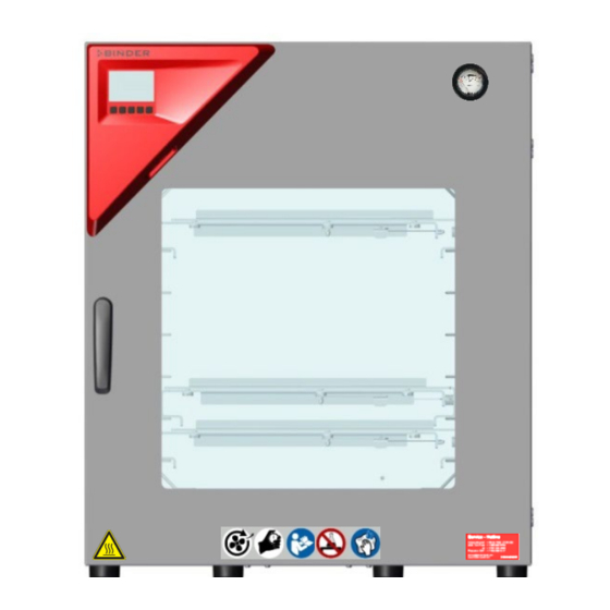
Chamber overview Figure 3: VDL 115 with MB2 controller Figure 4: VDL 115 with optional RD4 controller Area for electrical equipment Triangular instrument panel with chamber controller Chamber door Door handle Elastic-mounted safety glass window VDL (E3) 09/2019 Page 45/234... -
Page 46: Instrument Panel With Regular Mb2 Controller
Instrument panel with regular MB2 controller 5,7" controller display with touchscreen USB interface Pilot lamp Figure 5: Instrument panel with MB2 program controller and USB interface Instrument panel with optional RD4 controller RD4 controller display USB interface Figure 6: Instrument panel with RD4 controller and USB interface Connections on the rear of the chamber Rear control panel (12) -
Page 47: Figure 8: Rear Control Panel Vdl With Options
(1) (2) (3) VDL 23 (6) (4) (10) VDL 56 (10) (2) (3) VDL 115 (10) Figure 8: Rear control panel VDL with options VDL (E3) 09/2019 Page 47/234... -
Page 48: Area Classification, Information For The Zone Classification
Power cable Connection cable to Ethernet interface for computer communication 2 connection sockets (3a) top and (3b) below: (3a) Connection „Object temperature input“ (option) for optional object temperature display (3b) Connection „Analog output“ (option) for optional analog outputs for temperature and pres- sure Universal connection for inert gas / ambient air inlet “GAS/AIR”, adapter with hose olive ∅... -
Page 49: Area Classification Inside The Chamber
3.6.1 Area classification inside the chamber (12) Figure 9: Area classification of the closed chamber (view without housing, insulation, heater and outer chamber) Controller housing (swept with compressed air) Electrical installation area (swept with compressed air) Inner chamber (usable volume) Plug “Manual ventilation”... -
Page 50: Area Classification In The Surroundings Of The Chamber
3.6.2 Area classification in the surroundings of the chamber The VDL vacuum drying oven with the exception of the power plug is classified in category 3 in relation to the environment . It may be installed in areas in which explosive atmospheres may occur on a rare and temporary basis. -
Page 51: Area Classification In The Surroundings Of The Chamber: Extraction Lead To The Pump, Location Of The Pump
3.6.3 Area classification in the surroundings of the chamber: extraction lead to the pump, location of the pump Pump module with pump (example) front rear (rear) Pump (example) Figure 11: Area classification in the surroundings of the chamber during operation (example) Occurrence of an explosive atmosphere: explosive atmospheres may occur occasionally (interior of VDL and pump) explosive atmospheres may occur on a rare and temporary basis (environment) -
Page 52: Completeness Of Delivery, Transportation, Storage, And Installation
Note on second-hand chambers (Ex-Demo-Units): Second-hand chambers are chambers that were used for a short time for tests or exhibitions. They are thoroughly tested before resale. BINDER ensures that the chamber is technically sound and will work flawlessly. Second-hand chambers are marked with a sticker on the chamber door. Please remove the sticker before commissioning the chamber. -
Page 53: Guidelines For Safe Lifting And Transportation
Lift chambers size 115 with the aid of 6 people. • Permissible ambient temperature range during transport: -10 °C / 14 °F to +60 °C / 140 °F. You can order transport packing for moving or shipping purposes from BINDER Service. Storage Intermediate storage of the empty chamber is possible in a closed and dry room. - Page 54 NOTICE Danger by stacking. Damage to the chambers. ∅ Do NOT place vacuum drying ovens on top of each other. Zulässige Bereiche The VDL vacuum drying oven may be installed in areas in which explosive atmospheres may occur on a rare and temporary basis.
-
Page 55: Ventilation And Extraction (Technical Ventilation)
Electrical connection To completely separate the chamber from the power supply, you must disconnect the power plug. Install the chamber in a way that the power plug is easily accessible and can be easily pulled in case of danger. It as also possible to use a customer’s explosion-protected emergency stop switch. The chamber plug (power plug) is unprotected because it must be disconnected in case of an emergency to completely separate the chamber from the power supply. -
Page 56: Air Supply (Breaking The Vacuum) During Operation With Inert Gas
• Permissible ambient humidity: 70 % r.H. max., non-condensing. • Installation height: max. 2000 m / 6562 ft above sea level. The maximum permissible ambient temperature of the vacuum pumps delivered by BINDER is 40 °C / 104 °F. Compressed air / inert gas supply for sweeping the area for electrical equipment Before commissioning the chamber, connect the vacuum drying oven to the compressed air supply. -
Page 57: Lightning Protection Device
Lightning protection device The building in which the vacuum drying oven is installed must have a lightning protection system. All internal connections in the operator's building must contain lightning protection in accordance with EN/IEC 62305-3. Lightning protection measures must be taken in order to prevent melting and spraying effects. The opera- tor’s zone classification shall be used to plan lightning protection measures. -
Page 58: Figure 12: Operating The Expansion Racks
The vacuum expansion racks made of aluminum (also optio- nally available in stainless steel) allow low-loss heat transfer to the material. The strong tension causes the racks to fit tightly against the interior wall and their large-surface contact area ensures rapid and effective heat transfer. The removable rack holders allow for easy positioning. -
Page 59: Compressed Air / Inert Gas Connection For Sweeping The Area For Electrical Equipment And Triangle Instrument Box
Compressed air / inert gas connection for sweeping the area for electrical equipment and triangle instrument box The compressed air flows through the area for electrical equipment and the instrument box, which pre- vents a possible concentration of a solvent-containing atmosphere in the presence of live electrical com- ponents. -
Page 60: Setting The Overpressure For Sweeping With Compressed Air / Inert Gas
DANGER Risk of suffocation due to high concentration of inert gas. Death by suffocation. ∅ Do NOT set up chambers in non-ventilated recesses. Ensure active technical ventilation measures. Respect the relevant regulations for handling inert gas. When decommissioning the vacuum drying oven, shut off the inert gas supply: Close valve (6). -
Page 61: Pump Module (Option)
Sweeping after completion of chamber operation (recommended): • You can stop sweeping 15 minutes after turning off the chamber: Close the pressure regulator to (turn counterclockwise). • Check on the manometer that there is no longer any overpressure. Regarding use of the USB connection during chamber operation please observe the instructions given in chap. -
Page 62: Mounting
The following steps 6.3.1 to 6.3.3 are described in detail in the mounting instructions Art. no. 7001-0137. Please proceed accordingly. 6.3.1 Mounting • Placing the vacuum drying oven on the vacuum module • Mounting the connecting plate • Installing the suction line: Hose connection at the VDL vacuum connection (11) and fixing the hose at the housing rear •... -
Page 63: Connection Of An Extraction System At The Pump Module
Figure 18: Position of the Vacuum connection on the chamber rear (example size 115) When using a vacuum suction hose BINDER recommends the connection kit for the VP4 pump from BINDER (chap. 6.4.5). The optional pump module (chap.) provides an appropriate hose port on the rear. -
Page 64: Instructions For Using Vacuum Pumps
Install the switch gear box outside the hazardous area or provide it with explosion pro- tection. The ATEX Directive 2014/34/EU compliant pumps offered by BINDER provide an integral protective device and an integral explosion proof switch. Make sure that the vacuum source is designed for a gas inlet temperature corresponding to the used drying temperature, or take appropriate measures to cool down the extracted vapor before it enters into the vacuum source. - Page 65 Observe the permissible gas inlet temperature of the vacuum pump in use. Do NOT exceed this temperature. If the gas inlet temperature is too high and then becomes even warmer by compression in the pump, the resulting temperature (of the gas-solvent mixture inside the pump) could exceed the sol- vent’s temperature class and auto-ignition temperature .
-
Page 66: Vacuum Pump Vp4 (Option)
With a set-point temperature above 40 °C / 104 °F, take appropriate measures to cool down the sucked-in gas before its entry to the vacuum pump. The maximum permissible ambient temperature of the vacuum pumps supplied by BINDER is 40 °C / 104 °F. -
Page 67: Installation Of The Vacuum Pump Vp4 In The Pump Module (Option)
7001-0137. Connect the vacuum connection (6) (small flange DN 16) on the back of the chamber to a vacuum suction lead. When using a vacuum tube BINDER recommends the BINDER connection kit for VP4 (chap. 6.4.5). The optional pump module has a corresponding hose outlet on its rear. -
Page 68: Note On The Use Of A Flame Arrester
. The maximum permissible ambient temperature of the vacuum pump supplied by BINDER is 40 °C / 104 °F. 6.4.4 Note on the use of a flame arrester A flame arrester is not mandatory for VDL applications (TRBS 2152-4:2012). -
Page 69: Atex Connection Kit For Vacuum Pump Vp4 (Option)
6.4.5 ATEX connection kit for vacuum pump VP4 (option) Connection kit for VP4 (Art. no. 8012-0621) consists of: • Straining ring DN10/16 (3 pc.) • Universal centering ring DN10/16 (3 pc.) • Transition piece, adapter DN 16-10/8 (2 pc.) • Vacuum hose 10/8, 2 m / 78.7 in •... -
Page 70: Achieving Equipotential Bonding / Grounding Concept
Achieving equipotential bonding / Grounding concept For systems in potentially explosive areas, equipotential bonding acc. to IEC 60079-14 is required. All electrically conductive parts must be connected to the equipotential bonding system. Connections to the equipotential bonding system mustbe secured against automatic loosening. Grounding, i.e. -
Page 71: Figure 21: Mounting The Grounding Cable On The Vdl
How to achieve equipotential bonding when installing the VDL with a pump module is descri- bed in detail in the mounting instructions for the pump module (Art. No. 7001-0137) supplied with the pump module. Achieving equipotential bonding on the VDL Equipotential bonding must always be made via external grounding connections, so that no potential can be introduced in the event of a short circuit. -
Page 72: Electrical Connection
DANGER Explosion hazard by electric sparking due to missing or improperly implemented equipotential bonding. Serious injury or death from burns and / or explosion pressure. Connect all elements in the installation and loading area (VDL / pump module / pump) with the conductive surface and/or with each other. - Page 73 NOTICE Danger of incorrect power supply voltage due to improper connection. Damage to the equipment. Check the power supply voltage before connection and start-up. Compare the power supply voltage with the data indicated on the type plate. • When connecting, please observe the regulations specified by the local electricity supply company as well as the VDE directives (for Germany).
-
Page 74: Explosion Safety Tests Before Commissioning
Explosion safety tests before commissioning This chapter provides instructions for the user to ensure the safety of the system and to meet applicable regulations. Proper operation is only ensured after the test has been carried out and any necessary mea- sures implemented. -
Page 75: Objective Of Testing
Objective of testing Determine the suitability and functionality of safety-related measures. When testing the explosion safety of the system, evaluate the explosion protection plan and compare the target state derived from it with the actual state of the system (according to available test records): •... -
Page 76: Checking The Deadlines For The Recurring Tests
• Suitability and functionality of technical ventilation systems, gas warning systems, inerting devices, devices, protective systems, or control or regulating devices in the sense of Directive 2014/34/EU as well as explosive devices in the sense of TRGS 725 • Suitability and implementation of the measures determined on the basis of the risk assessment •... -
Page 77: Tests Of Technical Ventilation Systems, Gas Warning Devices, Inerting Devices, Devices, Protective Systems Or Safety, Control Or Regulating Devices, And Other Technical Devices For Explosion Protection
7.4.2 Tests of technical ventilation systems, gas warning devices, inerting devices, devices, protective systems or safety, control or regulating devices, and other technical devices for explosion protection Test content that has been checked and documented as part of conformity assessment procedures do not need to be checked again. -
Page 78: Functional Overview And Menu Structure Of The Controller
The MB2 program controller permits programming temperature and pressure cycles, and specifying special controller functions for each program section. You can enter values or pro- grams directly at the controller or use the APT-COM™ 4 Multi Management Software (option) specially developed by BINDER. Operating mode Temperature values... -
Page 79: Operating Functions In Normal Display
8.1.1 Operating functions in normal display Current operating mode Text list for information icons Date, time, authorization level of the logged-in user, memory Quick setpoint entry Continue to next screen Back to Normal display Information Program start Setpoint entry Event list Display of active alarms Access to main menu Figure 23: Operating functions of the MB2 controller in normal display (example values) -
Page 80: Display Views: Normal Display, Program Display, Chart-Recorder Display
8.1.2 Display views: Normal display, program display, chart-recorder display Press the Change view icon to toggle between normal display, program display and chart- recorder display. Press the Normal display icon to return from program display and chart recorder display back to Normal display. -
Page 81: Mb2 Controller Icons Overview
8.1.3 MB2 controller icons overview Navigation icons in Normal display Icon Signification Function Main menu Access from Normal display to the main menu Alarm Access from Normal display to the list of active alarms Event list Access from Normal display to the event list Access from Normal display to the setpoint entry menu: setpoint Setpoint setting entry for Fixed value operation, turning on/off temperature and/or... - Page 82 Functional icons in the chart recorder display Icon Signification Function Show legend Show legend Hide legend Hide legend Pause chart recorder and change to history display. Data recording History display continues. Curve selection Go to “Curve selection” submenu in the history display Go to “Search”...
-
Page 83: Mb2 Controller Operating Modes
8.1.4 MB2 controller operating modes The MB2 program controller operates in the following operating modes: • Fixed value operating mode The controller operates as a fixed-point controller, i.e., set-points for temperature and pressure can be defined, which are then maintained until the next manual change (chap. 10.1.1). •... -
Page 84: Main Menu
• Access to service data, controller reset to factory settings (chap. 8.1.5.3) • Available only for users with “Service” and “Admin” authorization level. Full functional range only for BINDER Service (users with “Service” authorization level). “Programs” submenu • Access to the controller’s program functions (chap. 17, 18, 19) •... -
Page 85: Settings" Submenu
8.1.5.3 “Service” submenu The “Service” submenu is available for users with “Service” or “Admin” authorization level. When logged- in with “Admin” authorization level the user will find information to tell the BINDER Service in service case. Main menu > Service... -
Page 86: Principle Of Controller Entries
8.1.6 Principle of controller entries In the selection and entry menus there are icons displayed in the footers which you can use to take over the entry or cancel it. Selection menu (example) Entry menu (example) After completing the settings there are the following possibilities: Press the Confirm icon to take over the entries and exit the menu or continue the menu se- quence. -
Page 87: Rd4 Controller
You can enter the desired set point values in the “Set points” menu directly at the controller or use the APT-COM™ 4 Multi Management Software (option) specially developed by BINDER. The controller offers various notifications and alarm messages with visual and audible indication. All con- troller setting remain valid until the next manual change. -
Page 88: Menu Structure Of The Controller And Access Levels
• Admin: The password enables access to advanced controller functions and settings. Factory setting is 00 01. • Service: The password enables access to all controller functions (for BINDER Service only). As soon as a password has been assigned, access to the respective functions is blocked and only available after entering the correct password. -
Page 89: Performance During And After Power Failures
Menu Required access level Functions • Configuration settings (only for BINDER Service) Service “Service” • Password changing for User and Admin • Export of configuration, logger, and service data Export: Any user • Import of configuration data Import: “Admin” Unless noted otherwise, the figure in this manual show the functional range, which is available for the user with “Admin”... -
Page 90: Rd4 Controller
• Performance after power failure during Week program operation The week program continues with the values corresponding to the current time. Power failure and power return are noted in the Event list (chap. 14). If during power failure an alarm has occurred (e.g., tolerance range, safety controller), confirm the alarm. See chap. -
Page 91: Overview Of The Drying Process
Overview of the drying process Required measures for operation with solvent-containing substances, which may be able to form an ex- plosive mixture with air: Starting situation • The vacuum drying oven and additional equipment have been set up and installed in ac- □... - Page 92 After completing the drying process or when cancelling the drying process When the pressure drops to pump pressure, the drying process is finished. If the drying monitoring (chap. 11.6) is activated, a corresponding message is displayed. • Make sure that the technical ventilation is activated □...
-
Page 93: Sweeping The Area For Electrical Equipment And Triangualr Instriment Box
Sweeping the area for electrical equipment and triangualr instriment box Before turning on it is mandatory to sweep the area for electrical equipment with compressed air or inert gas for at least 15 minutes. To do so, activate the customer's compressed air or inert gas supply. Sweeping must take place during the entire operating cycle;... -
Page 94: Standby Mode Turning On And Off The Vacuum Drying Oven
Standby mode Turning on and off the vacuum drying oven Before turning on the chamber, the following points must surely be met: • Equipotential bonding established (Chap. 6.6) • Technical ventilation is activated • 15 minutes sweeping the area for electrical equipment and the controller housing Activate the chamber only as required. -
Page 95: Rd4 Controller
9.5.2 RD4 controller Deactivating the Standby mode (turning on the chamber): After establishing power supply, press down the Standbybutton for 5 seconds to turn on the chamber. The controller shows normal display and controls temperature and pressure to the last entered values. Activating the Standby mode (turning off the chamber): To turn off the chamber press down the Standby button for another 5 seconds. -
Page 96: Rd4 Controller
Locked operation Provided that the user administration has been activated by the assignment of passwords for the different authorization types, the controller operation is first locked after turning on the unit, recognizable by the closed lock icon in the header. In the locked view the controller provides all display functions. -
Page 97: Loading
Loading Without technical ventilation the chamber must not be loaded with material containing sol- vents. The chamber cannot be loaded when turned off / in standby mode . Before loading the material to be loaded, note: When loading the chamber also in the context of intended use, an explosive mixture may form in the wor- king space. -
Page 98: Evacuation
DANGER Fire and explosion hazard when exceeding the auto-ignition temperature of the sol- vent. Serious injury or death from burns and / or explosion pressure. Take the auto-ignition temperature from the safety specifications of the solvent. In the case of solvent mixtures, use the lowest auto-ignition temperature. ... -
Page 99: Breaking The Vacuum (Flooding)
Breaking the vacuum (flooding) 9.9.1 Ventilation after completing the drying procedure (flooding with ambient air or inert gas) The duration of the drying procedure can be determined via the pressure display on the controller. When the decreasing pressure reaches the set-point value, the drying process is completed. If the drying moni- toring (chap. -
Page 100: Ventilation / Breaking The Vacuum In Case Of A Power Failure
Following evacuation, an inert gas, e.g., nitrogen, is led into the inner chamber via the fine dosing valve for inert gas (6), until pressure compensation with the atmosphere occurs. Depending on the individual application, you can perform a second evacuation and repeat the inert gas flooding. When the inert gas fine dosing valve is open, a maximum of approx. -
Page 101: Unloading The Loading Material
Hazard when opening the door after ventilation: After incorrect loading, open the door only when the inner temperature has sunk to ambient temperature. Prior to a termination of a not completed drying process make sure that the auto-ignition tem- peratureof the solvent has been determined correctly, and that the drying temperature reached far below this. -
Page 102: Removing The Full Condensate Catchpot Of The Pump
9.11 Removing the full condensate catchpot of the pump Do not remove the full condensate catchpot of the pump without technical ventilation Note the following points before removing the condensate catchpot: When removing the condensate catchpot spilling of the solvent may occur. •... -
Page 103: Set-Point Entry
Set-point entry Setting ranges Control ranges 10 °C / 18 °F to 16 °C / 28.8 °F above ambient Temperature 0.0 °C / 32 °F up to 220.0 °C / 428 °F temperature up to 110 ºC / 230 °F Pressure 0 mbar up to 1100 mbar 0 mbar up to 1100 mbar... -
Page 104: Direct Setpoint Entry Via Normal Display
• Select the field “Temperature” and enter the desired temperature setpoint. Confirm entry with Confirm icon. • Select the field “Pressure” and enter the desired pressure setpoint. Confirm entry with Confirm icon. When entering a value outside the setting range, the message: “Value outside of limits! (Min: xxx, Max: xxx)”... -
Page 105: Rd4 Controller
10.2 RD4 controller 10.2.1 Temperature set-point entry Required access level: “User”. Path: Normal display Setpoints Temperature Press the OK button to enable the setting. Temperature setting. The current setting flashes. Enter the desired set-point with the arrow buttons. Confirm the entry with the OK button. Temperature With the arrow-down button you can continue with the pressure set-point entry (chap. -
Page 106: Setting Special Controller Functions
Setting special controller functions You can set the following functions via the controller menu: • Activate / deactivate the Standby mode (chap. 9.5) • Use the optional connection “GAS/AIR2” (10) for ventilation (chap. 11.2) • Close all existing fine dosing valves (chap. 11.3) •... -
Page 107: Control On/Off" Menu
Example: Activated function “ Standby ” = 000000000000000 Deactivated function“ Standby ” = 000000000000000 11.1.1.2 “Control on/off” menu More functions are available via the “Control on/off” menu. Press the Setpoint setting icon to access the “Setpoint” setting menu from Normal display.. Setpoint >... -
Page 108: Quick Access Menu
• Press the OK button to enable the setting of the desired function and select the function’s switching state “1” (function activated) or “0” (function deactivated). With the Back button you can go back to the “Setpoints” submenu and, repeatedly pressing it, to Nor- display. -
Page 109: Mb2 Controller
11.2.1 MB2 controller Press the Setpoint setting icon to access the “Setpoint” setting menu from Normal display.. Setpoint > Fixed value operation setpoints > Functions on/off Path: “Functions on/off” menu. Mark the checkbox of the function “GAS/AIR 2” to acti- vate it and press the Confirm icon. -
Page 110: Close All Valves
11.3 Close all valves Close all existing fine dosing valves 11.3.1 MB2 controller Press the Setpoint setting icon to access the “Setpoint” setting menu from Normal display.. Setpoint > Fixed value operation setpoints > Functions on/off Path: “Functions on/off” menu. Mark the checkbox of the function “Close all valves”... -
Page 111: Activating / Deactivating Temperature Control
11.4 Activating / deactivating temperature control 11.4.1 MB2 controller Press the Setpoint setting icon to access the “Setpoint” setting menu from Normal display.. Setpoint > Control on/off Path: “Setpoints” menu. Select the field “Control on/off” (example: deactivated temperature control). Mark / unmark the “Temperature” checkbox to activate / deactivate temperature control and press the Confirm icon. -
Page 112: Activating / Deactivating Pressure Control
If the setting “Off” (temperature control deactivated) has been selected, the information message “Tempe- rature control off” is displayed. The „Info“ icon flashes slowly. The actual temperature value continues to be displayed in Normal display. 11.5 Activating / deactivating pressure control When operating the chamber without a vacuum connection, you can deactivate pressure control with the to avoid alarms of the pressure system. -
Page 113: Rd4 Controller
11.5.2 RD4 controller Path: Normal display Pressure control Press the OK button to enable the setting. Setting the “Pressure control” function. Use the arrow buttons to select between “On” (pressure control acti- ve) and “Off” (pressure control deactivated). Confirm the setting with the OK button. After confirming with the OK button or with the Back button you go back to Normal display. -
Page 114: Drying Monitoring
11.6 Drying monitoring Pressure Time Figure 25: Schematic timing of the drying process and drying monitoring Procedure: • Enter the temperature set-point. The previously entered pressure setpoint is not used with this function. It remains saved. The drying monitoring uses a fixed minimum pressure setpoint. -
Page 115: Mb2 Controller
11.6.1 MB2 controller In Normal display press the Program start icon to access the “Program start” menu. “Program start” menu with the selected Drying monito- ring program. • In the field “Program” select the setting “Drying monitoring” program. • Select the field “Program start” and enter the desired program start time in the “Program start” entry menu. -
Page 116: Rd4 Controller
• All passwords can be changed in the “log out” submenu (chap. 12.1.3). “Service” authorization level • Authorization level only for BINDER service • Extensive authorization for controller operation and configuration, access to service data • The passwords for “Service”, “Admin” and “User” authorization levels can be changed in the “log out”... - Page 117 “User” authorization level • Standard authorization level for the chamber operator • Authorization for operating the controller functions required for operating the chamber. • No authorization for controller configuration and network settings. The “Settings” and “Service” sub- menus of the main menu are not available. •...
- Page 118 Operation after user login At user login, the authorization level is selected and confirmed by entering the respective pass- word. Following user login, controller operation is available, recognizable by the open-lock icon in the header. The available controller functions correspond to the user’s authorization level. Password protection activated for all levels: operation without user login is locked If passwords have been assigned for all authoriza- tion levels, the controller is locked without registra-...
- Page 119 Information window To check the authorization level of the user currently logged-in, select in Normal display the arrow far right in the display header. The information window shows date and time, the controller’s free memory space and under “Authorizati- on” the authorization level of the current user. If passwords have been assigned for all authorization levels, a user without login (password entry) has no authorization.
-
Page 120: Log In
12.1.2 Log in Main menu > User > Log in Path: Controller without a user logged-in Selection of user type (example) All selection possibilities are password protected Controller with logged-in user After completing the settings, press the Confirm icon to take over the entries and exit the menu, or press the Close icon to exit the menu without taking over the entries. -
Page 121: Log Out
12.1.3 Log out Main menu > User > Log out Path: Controller with Controller logged-in user without a user (e.g. “Admin” logged-in authorization) 12.1.4 User change If the password function has been deactivated (chap.12.1.5.2) this function is not available. Main menu > User > User change Path: Controller with logged-in user... -
Page 122: Password Assignment And Password Change
12.1.5 Password assignment and password change This function is not available for a user logged-in with “User” authorization. 12.1.5.1 Password change A logged-in user can change the passwords of his current level and of the next lower level(s). Example: A user with “Admin” authorization can change the passwords for the “Admin” and “User” autho- rization levels. - Page 123 In the “Keyboard switch” window you can select different keyboards to enter uppercase and lowercase letters, digits, and special characters. All types of characters can be combined within one single pass- word. Example: access the digit entry window Entry of digits To confirm the entry, press the Confirm icon.
-
Page 124: Deleting The Password For An Individual Authorization Level
12.1.5.2 Deleting the password for an individual authorization level A user logged-in with “Service” or “Admin” authorization can delete the passwords of his current level and of the next lower level(s). To do this no password is entered during a password change. Main menu >... -
Page 125: New Password Assignment For "Service" Or "Admin" Authorization Level When The Password Function Was Deactivated
12.1.5.3 New password assignment for “service” or “admin” authorization level when the password function was deactivated If the password protection for an authorization level has been deactivated, i.e., no password is assigned, no login for this level is possible. Therefore access to this authorization level is available without login. If the password for the “Service”... -
Page 126: Activation Code
12.1.6 Activation code Certain functions of the controller can be unlocked with a previously generated activation code. The activation code enables access to functions available only in the “Service” authorization level by users without a “Service” authorization. Such functions include e.g., adjustment or extended configurati- ons. -
Page 127: Rd4 Controller
12.2 RD4 controller 12.2.1 Password request To access menus for which access is restricted, you must enter the corresponding password. After calling the appropriate menu function with the OK button the password request appears. Password request. The left two digits are flashing. Enter the desired numbers with the arrow buttons. -
Page 128: Assign And Modify The User Password
12.2.2.1 Assign and modify the User password Path: Normal display Settings Chamber Password User Press the OK button to enable the setting. Setting the User password. The left two digits are flashing. Enter the desired numbers with the arrow buttons. Confirm the setting with the OK button. -
Page 129: General Controller Settings And Information
General controller settings and information 13.1 MB2 controller Most of the general settings can be accessed in the “Settings” submenu, which is available for users with “Service” or “Admin” authorization level. It serves to enter date and time, select the language for the con- troller menus and the desired temperature unit and to configure the controller’s communication functions. - Page 130 Or later: Main menu > Settings > Date and time Path: “Date and time” submenu. “Date / time” entry menu. Select the field “Date / time”. Enter date and time and press the Confirm icon. “Date and time” submenu. “Date and time” submenu. In the field “Daylight saving time switch”...
-
Page 131: Selecting The Temperature Unit
13.1.3 Selecting the temperature unit Following start-up of the chamber: Or later: Main menu > Settings > Chamber Path: Select the desired temperature unit and press the Confirm icon. Change of the temperature unit between °C and °F. If the unit is changed, all values are converted accordingly C = degree Celsius 0 °C = 31°F... -
Page 132: Touchscreen Calibration
• Select the field “Brightness”. Move the grey slide to the left or right to define the brightness of the display • left = darker (minimum value: 0) • right = brighter (maximum value: 100) Press the Confirm icon. • Select the field “Wait time for screen saver” and enter the desired waiting time for the screen saver in seconds. -
Page 133: Event List
The waiting icon shows how much time there is left to touch the currently activated box. If the box is not touched withing this period, calibration is aborted and the display changes to Normal display. After completing the calibration, i.e., touching all four boxes, the display changes to Normal display. 13.1.5 Event list The “Event list”... -
Page 134: Current Operating Parameters
13.1.8 Technical chamber information Main menu > Device info Path: Chamber name and setup Versions of CPU, I/O module and safety con- for BINDER troller Service Information on digital and analog inputs and for BINDER outputs and phase angle outputs... -
Page 135: Rd4 Controller
13.2 RD4 controller The general settings can be accessed in the “Settings” submenu, which is available for users with “Ser- vice” or “Admin” authorization level. It serves to enter date and time, select the language for the controller menus and the desired temperature unit and to configure the controller’s communication functions. The display of some network settings is available for all users in the “Chamber info”... -
Page 136: Setting The Current Date
13.2.3 Setting the current date Required access level: “Admin”. Following start-up of the chamber (chap. 9.6.1), it is “User”. Path: Normal display Settings Chamber Date Press the OK button to enable the setting. Setting the date: day The current setting flashes. Enter the current day with the arrow but- tons. -
Page 137: Setting The Current Time
13.2.4 Setting the current time Required access level: “Admin”. Following start-up of the chamber (chap. 9.6.1), it is “User”. Path: Normal display Settings Chamber Time Press the OK button to enable the setting. Setting the time: hours The current setting flashes. Enter the current hour with the arrow but- tons. -
Page 138: Setting The Chamber Address
13.2.6 Setting the chamber address This setting is required for the communication with the BINDER APT-COM™ 4 Multi Management Soft- ware. The chamber address settings in the chamber controller and in the software must be identical. Required access level: “Admin”. -
Page 139: Temperature Safety Devices
Temperature safety devices 14.1 Over temperature protective device class 2 (thermal switch) The chamber is equipped with an internal temperature safety device class 2.0 acc. to DIN 12880:2007. It serves to protect the chamber and prevent dangerous conditions caused by major defects of the cham- ber. -
Page 140: Setting The Safety Controller
• Offset: Offset value, maximum overtemperature above any active temperature set point. The resulting maximum temperature changes internally and automatically with every temperature set-point change. MB2 controller: This setting is recommended for program operation. It is important to check the sa- fety controller set-point and safety controller mode occasionally, as it does not offer a fix, independent limit temperature value, which would never be exceeded. -
Page 141: Rd4 Controller: Setting The Safety Controller Mode
14.2.2.2 RD4 controller: Setting the safety controller mode Required access level: “User”. Path: Normal display Setpoints Safety controller Mode Press the OK button to enable the setting. Setting the safety controller mode The current setting flashes. Use the arrow buttons to select between LIMI (Limit) and OFFS (Offset). -
Page 142: Message And Measures In The State Of Alarm
14.2.3 Message and measures in the state of alarm 14.2.3.1 MB2 controller The state of alarm is indicated visually and additionally with an audible alert if the buzzer is enabled (chap. 16.4). The alarm remains active until it is acknowledged on the controller and the inner temperature falls below the set safety controller setpoint. -
Page 143: Function Check
Normal display showing safety controller alarm (sample values) Safety controller Note: When the safety controller class 2 had been activated you should disconnect the chamber from the power supply and have an expert examine and rectify the cause of the fault. 14.2.4 Function check Check the safety controller at appropriate intervals for its functionality. -
Page 144: Alarm Condition
After completing the settings, press the Confirm icon to take over the entries and exit the menu, or press the Close icon to exit the menu without taking over the entries. 15.1.2 Alarm condition If there are actual values outside the tolerance range the following information icons for the corresponding parameter are displayed: Icon Signification... -
Page 145: Setting The Delay Time For Pressure Tolerance Range Alarm
With the arrow-down button you can now change to setting the delay for pressure tolerance range alarm. With the Back button you can go back to the “Various” submenu and, repeatedly pressing it, to Normal display. 15.2.3 Setting the delay time for pressure tolerance range alarm Path: Normal display Settings... -
Page 146: Notification And Alarm Functions
Notification and alarm functions 16.1 Information messages 16.1.1 MB2 controller Information messages are indicated by information icons displayed in the screen header in Normal dis- play An information icon serves as an indication of a certain condition. If this condition persists, in some cases an alarm will be triggered after a fix or configurable interval. As long as the condition persists, the information icon therefore continues to be displayed also in state of alarm. -
Page 147: Rd4 Controller
Information messages overview: Information Start after Condition Text information icon condition occurred Temperature setpoint Deactivated temperature control value display shows immediately “ – – – – ” Pressure setpoint value Deactivated pressure control display shows immediately “ – – – – ” Pressure threshold of 100 mbar not “Pressure threshold not immediately... - Page 148 Condition Information message Moment of information message Recommended maintenance interval (one year of operati- “Service due!” “Service due!” on) is over. With activated drying monito- “Drying finished” After the solvent has evaporated ring: Drying finished Press the OK button to confirm the information message. Additionally the activated functions are indicated by an icon in Normal display showing the number of the respective function.
-
Page 149: Alarm Messages
16.2 Alarm messages 16.2.1 MB2 controller Alarm messages overview: Start after Condition Alarm message condition occurred The current actual temperature value after configurable time is outside the tolerance range (chap. “Temperature range” (chap. 15.1.1) Factory setting: 10 minutes after configurable time The current actual pressure value is “Pressure range”... -
Page 150: Rd4 Controller
Normal display in state of alarm (example). (a) Screen header flashing in red color and showing the alarm message (b) Alarm icon on the bottom of the screen: change to the list of active alarms and alarm acknowledgement 16.2.2 RD4 controller In the event of equipment failures, when the temperature and / or pressure deviate from the set tolerance range limits, optical and possibly acoustic alarm messages are given out via the controller. -
Page 151: Resetting An Alarm
Start after Condition Alarm message condition occurred Actual temperature value Inner chamber temperature sensor display shows immediately defective. Heater turns off. “ – – – – ” Heater temperature sensor defective. “Heater temp.sensor” immediately Heater turns off. Actual pressure value display Pressure sensor defective shows immediately... -
Page 152: Activating / Deactivating The Audible Alarm (Buzzer)
16.4 Activating / deactivating the audible alarm (buzzer) 16.4.1 MB2 controller Main menu > Settings > Chamber Path: “Chamber” submenu (example). In the field “Audible alarm” select the desired setting “off“ or “on” and press the Confirm icon. 16.4.2 RD4 controller Path: Normal display Settings... -
Page 153: Mb2 Controller: Timer Program (Stopwatch Function)
MB2 controller: Timer program (stopwatch function) During an entered duration the controller constantly equilibrates to the setpoints entered in Fixed value operation mode (temperature, pressure, configuration of the special controller functions). This duration can be entered as a “Timer program”. During the program runtime, any setpoint changes do not become effective;... -
Page 154: Performance During Program Delay Time
17.1.1 Performance during program delay time During the configured program delay time until program start, the controller equilibrates to the current setpoints of Fixed value operation mode. Modifications of these setpoints are possible but become effec- tive only after the timer program is finished. When the configured moment for program start is reached, the program delay time ends and the program starts running. -
Page 155: Mb2 Controller: Time Programs
MB2 controller: Time programs The MB2 program controller permits programming time programs with real-time reference. It offers 25 program memory positions with up to 100 program sections each. For each program section you can enter a temperature set-point, a pressure set-point, section duration, type of temperature and pressure transition (ramp or step), the switchings states of the special controller functions and the tolerance ranges. -
Page 156: Performance During Program Delay Time
After completing the settings, press the Confirm icon to take over the entries and exit the menu. The program starts running. If instead you press the Close icon to exit the menu without taking over the entries, the program will not start. -
Page 157: Performance After The End Of The Program
18.3 Performance after the end of the program After the end of the program the message “Device changes to fixed value operation mode” appears on the screen. Press the Confirm icon. As long as the message has not been confirmed, the setpoint of the last program section remains effecti- ve. -
Page 158: Creating A New Time Program
18.4 Creating a new time program Main menu > Programs > Time program Path: Enter the program name and, if desired, additi- “Time program” menu: onal program information in the corresponding overview of the existing programs. fields. Select an empty program place. Press the Confirm icon. -
Page 159: Deleting A Time Program
Program editor: “Edit program” menu Select the desired function and press the Confirm icon. The program editor offers following options: • Change the program name • Copy program • Replace program: Replacing an new or an existing program with the copied program. This menu point is visible only after a program has been copied. -
Page 160: Section Editor: Section Management
18.6 Section editor: section management Main menu > Programs > Time program Path: Select the desired program. Program view. Section view (example: section 1). Select the desired program section There are the following options: (example: section 1) ... -
Page 161: Add A New Program Section
18.6.1 Add a new program section Section editor: “Edit section” menu. Select “Create new section” and press the Confirm icon. Then select whether to insert the new section befo- re or after the current section. Press the Confirm icon. The new section opens. 18.6.2 Copy and insert or replace a program section Program view. -
Page 162: Deleting A Program Section
Press the Edit icon to open the section editor if you want the current section to be replaced or the copied section to be inserted before or after it Program view. Section view (example: section 1). Select the section to be replaced or before or Press the Edit icon to open the section editor after which the copied section shall be inser- ted (example: section 2) and press the Con-... -
Page 163: Value Entry For A Program Section
18.7 Value entry for a program section Main menu > Programs > Time program Path: Select the desired program and section. The section view gives access to all parameters of a program section. You can enter or modify the valu- Program name and section number Section duration Type of setpoint transition: ramp or step... -
Page 164: Set-Point Ramp And Set-Point Step
18.7.2 Set-point ramp and set-point step You can define the type of temperature and pressure transitions for each individual program section. “Ramp” mode: Gradual changes of temperature and pressure The set-point of a given program section functions as the section’s start temperature. During the section’s duration, the set-point gradually passes to the set-point of the subsequent program section. -
Page 165: Special Controller Functions
“Ramp” and “Step” mode example (representation of a temperature course) W/°C t/min. Corresponding program table Duration Temperature Pressure Section No. Ramp or Step [hh:mm:ss] [°C] mbar] 00:10:00 40.0 xxxx Step 00:20:00 60.0 xxxx Step 00:10:00 80.0 xxxx Step 00:20:00 40.0 xxxx Step 00:10:00... -
Page 166: Setpoint Entry
Section view indicating the controller functions. The functions are displayed from right to left. Activated function: switching status “1” (On) Deactivated function: switching status “0” (Off) Example: Activated function “Standby” = 000000000000000 Deactivated function“Standby” = 000000000000000 18.7.4 Setpoint entry • Select the field “Temperature” and enter the desired temperature setpoint. Setting range: 0.0 °C up to 220.0 °C Confirm entry with Confirm icon. -
Page 167: Repeating One Or Several Sections Within A Time Program
Section view, showing the temperature tolerance range • Select the field “Tolerance band min” and enter the desired lower tolerance band value. Setting range: -99999 to 99999. Confirm entry with Confirm icon. The controller returns to the section view. • Select the field “Tolerance band max” and enter the desired upper tolerance band value. Setting ran- ge: -99999 to 99999. -
Page 168: Saving The Time Program
• Select the field “Number of repetitions” and enter the desired number of repetitions. Setting range: 1 to 99, and -1 for infinite. Confirm entry with Confirm icon. The controller returns to the section view. • Select the field “Start section for repetition” and enter the section number, at which the repetition should start. -
Page 169: Mb2 Controller: Week Programs
MB2 controller: Week programs The MB2 program controller permits programming week programs with real-time reference. It offers 5 week program places in total with up to 100 shift points for each week program. Main menu > Programs> Week program Path: For each program section you can enter the moment in time, the temperature set-point, the pressure set- point, and the switching states of the special controller functions. -
Page 170: Cancelling A Running Week Program
After starting the week program, the previously entered week program setpoints are active and will be equilibrated according to the current time. Information on the bottom of the screen indicates the currently running program. 19.2 Cancelling a running week program Press the Program cancelling icon to cancel the program. -
Page 171: Creating A New Week Program
19.3 Creating a new week program Main menu > Programs > Week program Path: Enter the program name and, if desired, addi- “Week program” menu: tional program information in the correspon- overview of the existing programs. ding fields. Select an empty program place. Select the set-point course “Ramp”... -
Page 172: Program Editor: Program Management
19.4 Program editor: program management Main menu > Programs > Week program Path: Program view (example: program 1). “Week program” menu: If a new program has been created, there is overview of the existing programs. just one program section. Select an existing program (example: pro- gram 1). -
Page 173: Deleting A Week Program
Program view. To add a new section, select “Create new section” and press the Confirm icon. With a new section no weekday is specified. There- fore the section is first marked in red and cannot be The program view opens. saved. -
Page 174: Section Editor: Section Management
19.5 Section editor: section management Main menu > Programs > Week program Path: Select the desired program. Program view. Section view (example: section 2). Select the desired program section There are the following options: (example: section 2) ... -
Page 175: Add A New Program Section
19.5.1 Add a new program section Section editor: “Edit section” menu. Program view. Select “Create new section” and press the With a new section no weekday is specified. There- Confirm icon. fore the section is first marked in red and cannot be saved. -
Page 176: Deleting A Program Section
Select “Replace section” to replace the selected sec- tion with the copied section Select “Insert section” to additionally add the copied section. Press the Confirm icon. If you selected “Insert section” the sections are auto- matically arranged in the correct chronological order. Section editor: “Edit section”... -
Page 177: Weekday
19.6.2 Weekday In the field “Weekday” select the desired weekday. With “Daily” selected, this section will run every day Section view. at the same time. 19.6.3 Start time Section view. Entry menu “Moment”. Select the field “Moment”. Select with the arrow keys the desired start mo- ment of the section and press the Confirm icon. -
Page 178: Setpoint Entry
19.6.4 Setpoint entry • Select the field “Temperature” and enter the desi- red temperature setpoint. Setting range: 0.0 °C up to 110.0 °C Confirm entry with Confirm icon. The controller returns to the section view. • Select the field “Pressure” and enter the desired pressure setpoint. -
Page 179: Network And Communication
Network and communication 20.1 MB2 controller For the network and communication settings at least the “Admin” authorization level is required. 20.1.1 Ethernet 20.1.1.1 Configuration Main menu > Settings > Ethernet Path: “Ethernet” submenu. • In the field “IP address assignment” select the desired setting “Automatic (DHCP)“... -
Page 180: Display Of Mac Address
This controller menu serves to configure the web server. Then you can enter the chamber’s IP-address in Chamber information > Ethernet. The BINDER web server the Internet. The IP address is available via opens. Enter the user name and password which have been assigned for the web server in the controller menu. -
Page 181: E-Mail
20.1.3 E-Mail As soon as an alarm was triggered, an e-mail is sent to the configured e-mail address. Main menu > Settings > Email Path: E-mail address entry: “Email” submenu. Select the desired e-mail address field and enter the e-mail address. You can use the Keyboard change icon for entry. -
Page 182: Rd4 Controller: Ethernet Network Settings
The settings in the Ethernet submenu are used for networking chambers with an Ethernet interface , e.g. to connect them with BINDER’s APT-COM™ 4 Multi Management Software (option, chap. 25.1). 20.2.1 Showing the network settings Required access level: “User”. The “Ethernet” submenu offers to subsequently or individually access the following information: •... -
Page 183: Showing The Subnet Mask
20.2.1.3 Showing the subnet mask Path: Normal display Chamber info Ethernet Subnet mask Display of the subnet mask (examp- Toggle forth and back with the Back button and the OK button. 0.0.0.0 Subnet mask With the arrow-down button you can now change to the next parameter (standard gateway). With the Back button you can go back to the “Ethernet”... -
Page 184: Showing The Dns Chamber Name
20.2.1.6 Showing the DNS chamber name Path: Normal display Chamber info Ethernet chamber name Display of the DNS chamber name (example) Toggle forth and back with the Back button and the OK button. DNS chamber name BinderRD4-000cd80a281 With the Back button you can go back to the “Ethernet” submenu and, repeatedly pressing it, to Normal display. -
Page 185: Selecting The Type Of Assignment Of The Dns Server Address (Automatic / Manual)
20.2.2.2 Selecting the type of assignment of the DNS server address (automatic / manual) Access to this function is possible only if automatic IP address assignment has been selected (chap. 20.2.2.1) Path: Normal display Settings Ethernet DNS server Press the OK button to enable the setting. Selection of the type of assignment of the DNS server address. -
Page 186: Setting The Subnet Mask
IP address assignment (sample values). The third section of the IP address is shown. Enter the desired value with the arrow buttons. Use the OK button to confirm the entry and proceed to the last section of the IP address. IP address IP address assignment (sample values). -
Page 187: Assigning The Dns Server Address
Principle of entry: • Use the OK button to select the desired section of the standard gateway 1/4, 2/4, 3/4, 4/4 in the upper display line • Use the Arrow buttons to enter the value for the selected section of the standard gateway •... -
Page 188: Recorded Data
• Chamber data for BINDER Service “DL2” This data is intended for use by BINDER Service. It also contains information from the self-test func- tion. The storage rate is fix (1 minute). Temperature values are always given out in °C. -
Page 189: Deleting The Data Recorder
When importing a configuration via USB stick (chap. 22.3.2) and when loading a new firmware version by BINDER service, the entire data memory is deleted. BINDER service can also install the configuration by means of a setup program without deleting the data. Regardless of this, BINDER Service can delete the data via a setup program NOTICE Loading a new configuration via USB-Stick leads to deleting the data recorder. -
Page 190: Rd4 Controller
• Recorder data • DL1 (chamber data for the user): “DL1_[MAC address of the chamber].csv” • DL2 (chamber data for BINDER Service): “DL2_[ MAC address of the chamber].csv” • Event list: “EvList_[MAC address of the chamber].csv” For detailed information on the file content see chap. 21.1. -
Page 191: Connecting The Usb Stick
• Service data The "Service" folder is created on the USB stick and can be sent to BINDER Service. In addition to the configuration and recorder data, it contains further service-relevant information. 22.3.1 Connecting the USB stick Connect the USB stick to the interface located in the triangular instrument panel. -
Page 192: Ongoing Data Transfer
With the arrow-down button you can now change to the next function. Function “Export service data”. To write the chamber data from the controller to the USB stick, press the OK button. Export service data 22.3.4 Ongoing data transfer A moving arrow symbol indicates the progress of the data transfer. Example: Data recording is running. -
Page 193: Mb2 Controller: Chart Recorder Display
MB2 controller: Chart recorder display This view offers graphic representation of the measurement course. Data representation imitates a chart recorder and allows recalling any set of measured data at any point of time taken from the recorded period. 23.1 Views Press the Change view icon to access the pen recorder display. - Page 194 History display: Curve selection Curve selection Press the Curve selection icon to access the “Curve selection” submenu. “Curve selection” submenu. Select the curves to be displayed by checking the checkbox of the corresponding parameter. Press the Confirm icon History display: Search the required instant Search Press the Search icon to access the “Search”...
- Page 195 History display: Zoom function Zoom Press the Zoom icon to access the “Zoom” submenu. “Zoom” submenu. Select the zoom factor and press the Confirm icon History display: Show and hide scroll buttons to scroll to an instant Show scroll buttons Hide scroll buttons Press the Show scroll buttons icon to access the “Page selection”...
-
Page 196: Setting The Parameters
23.2 Setting the parameters This menu allows setting the storage interval, the type of values to be shown and the scaling of the tem- perature and humidity charts. Main menu > Settings > Measurement chart Path: “Measurement chart” submenu. • Select the field “Storage interval” and enter the desired storage interval. Confirm entry with Confirm icon. -
Page 197: Reference Measurements
In case the temperature probe is a thermo element, mount it so it is electrically insulated from the rack. If you note an excessive divergence between the controller and reference temperatures, please contact BINDER Service to calibrate the temperature controller. VDL (E3) 09/2019 Page 197/234... -
Page 198: Options
25.1 APT-COM™ 4 Multi Management software (option) The chamber is regularly equipped with an Ethernet interface (2) that can connect the BINDER APT- COM™ 4 Multi Management Software. • RD4 controller: The MAC Address is indicated in the “Ethernet” controller menu (chap. 20.2.1.1). -
Page 199: Object Temperature Display With Flexible Pt 100 Temperature Sensor (Option)
Connections at the measuring access port • At the inner side of the measuring access port you can solder up to 9 cables. The inside connections must be insulated against each other and against ground. Use 300 °C / 572 °F solder. •... -
Page 200: Display On The Rd4 Controller
The object temperature data are put out together with the data of the temperature controller to the cham- ber’s interface and can be documented by the APT-COM™ 4 Multi Management Software (option, chap. 25.1) developed by BINDER. VDL (E3) 09/2019... -
Page 201: Cleaning And Decontamination
Cleaning and decontamination Clean the chamber after each use to avoid potential corrosion damage by ingredients of the charging material. . 26.1 Safety instructions on cleaning and decontamination During cleaning and decontamination, no explosive atmosphere may be present in the installation area of the chamber and inside the chamber. -
Page 202: Cleaning
Any corrosive damage that may arise following use of other cleaning agents is excluded from liability by BINDER GmbH. Any corrosive damage caused by a lack of cleaning, is excluded from liability by BINDER GmbH. NOTICE Danger of corrosion by using unsuitable cleaners. -
Page 203: Decontamination / Chemical Disinfection
For chemical disinfection, we recommend using the disinfectant spray Art. No. 1002-0022. Any corrosive damage that may arise following use of other disinfectants is excluded from liability by BINDER GmbH. With every decontamination / disinfection method, always use adequate personal safety con- trols. -
Page 204: Maintenance And Service, Troubleshooting, Repair, Testing
In case of eye contact, the disinfectant spray may cause eye damage due to chemical burns. Follow the operating instructions and safety hints labeled on the bottle of the disin- fectant spray. Recommended precautions: To protect the eyes use sealed protective goggles. CAUTION Danger of chemical burns due to eye contact with desinfactants. -
Page 205: Simple Troubleshooting
If there are is a technical fault or shortcoming, take the chamber out of operation and inform BINDER Service. If you are not sure whether there is a technical fault, pro- ceed according to the following list. If you cannot clearly identify an error or there is a technical fault, please contact BINDER Service. - Page 206 Chamber permanently turned 115V or 230V. off. Chamber fuse has responded. Check chamber fuse. Controller defective. Contact BINDER Service. Heating Wait until pressure threshold is Pressure threshold of 100 mbar reached and heater released. not reached. No heater release. Select suitable pressure setpoint.
- Page 207 MB2 controller: Log in with the re- Menu functions not available Menu functions not available. with current authorization level. quired higher authorization. or contact BINDER service to obtain an activation code (chap. 12.1.6). No access to controller Incorrect password. Contact BINDER service.
-
Page 208: Maintenance, Service
∅ Do NOT remove the rear panel of the chamber. Make sure that general maintenance work will be conducted by licensed electricians with additional skills in explosion protection (ATEX) or experts authorized by BINDER. VDL (E3) 09/2019 Page 208/234... -
Page 209: Maintenance Intervals
Service manual (customer version. Maintenance of the pump or vacuum system must be performed regularly as specified by the manufactu- rer. When using the VP4 pump provided by BINDER, note the information given by the pump manufactu- rer. -
Page 210: Service Reminder
Service due! After one week of operation, the message reappears. 27.4.3 BINDER Service contact data We recommend taking out a maintenance agreement. Please consult BINDER Service. BINDER telephone hotline: +49 (0) 7462 2005 555 BINDER fax hotline: +49 (0) 7462 2005 93555 BINDER e-mail hotline: service@binder-world.com... -
Page 211: Sending The Chamber Back To Binder Gmbh
27.5 Sending the chamber back to BINDER GmbH If you return a BINDER product to us for repair or any other reason, we will only accept the product upon presentation of an authorization number (RMA number) that has previously been issued to you. An authorization number will be issued after receiving your complaint either in writing or by telephone prior to your sending the BINDER product back to us. -
Page 212: Decommissioning
(Elektro- und Elektronikgerätegesetz, ElektroG from 20 Oc- tober 2015, BGBl. I p. 1739) or contact BINDER service who will organize taking back and disposal of the chamber according to the German national law for electrical and electronic equipment (Elektro- und Elekt- ronikgerätegesetz, ElektroG from 20 October 2015, BGBl. -
Page 213: Disposal Of The Chamber In The Member States Of The Eu Except For The Federal Republic Of Germany
According to Annex I of Directive 2012/19/EU of the European Parliament and of the Council on waste electrical and electronic equipment (WEEE), BINDER devices are classified as “monitoring and control instruments” (category 9) only intended for professional use“. They must not be disposed of at public coll- ecting points. -
Page 214: Disposal Of The Chamber In Non-Member States Of The Eu
If your distributor is not able to take back and dispose of the chamber, please contact BINDER service. Certified companies disassemble waste (used) BINDER equipment in primary substances for recycling according to Directive 2012/19/EU. The devices must be free from toxic, infectious or radioactive sub- stances in order to eliminate any health hazards to the employees of the recycling companies. -
Page 215: Technical Description
(certified since December 1996 by TÜV CERT). All test equipment used is subject to the administration of measurement and test equipment that is also a constituent part of the BINDER QM DIN EN ISO 9001 systems. They are controlled and calibrated to a DKD-Standard at regular intervals. - Page 216 Chamber size External dimensions Chamber with optional pump module mm / inch 523 / 20.59 637 / 25.10 742 / 29.21 Width, net mm / inch 1425 / 56.10 1542 / 60.71 1669 / 65.71 Height, net mm / inch 491 / 19.33 540 / 21.26 660 / 25.98...
-
Page 217: Equipment And Options (Extract)
+22 °C +/- 3 °C / 71.6 °F +/- 5.4 °F and a power supply voltage fluctuation of +/- 10 %. Technical data is determined in accordance to BINDER Factory Standard Part 2:2015 and DIN 12880:2007. -
Page 218: Accessories And Spare Parts (Extract)
29.5 Accessories and spare parts (extract) BINDER GmbH is responsible for the safety features of the chamber only, provided skilled electricians or qualified personnel authorized by BINDER perform all maintenance and repair, and if components relating to chamber safety are replaced in the event of failure with original spare parts. - Page 219 Spatial temperature measurement including certificate (9 measuring 8012-0916 points) Spatial temperature measurement including certificate (15 measuring 8012-0919 points) Calibration of pressure including certificate 8012-0440 For information on components not listed here, please contact BINDER Service. VDL (E3) 09/2019 Page 219/234...
-
Page 220: Dimensions
29.6 Dimensions 29.6.1 VDL 23 (Dimensions in mm) VDL (E3) 09/2019 Page 220/234... -
Page 221: Vdl 56
29.6.2 VDL 56 (Dimensions in mm) VDL (E3) 09/2019 Page 221/234... -
Page 222: Vdl 115
29.6.3 VDL 115 (Dimensions in mm) VDL (E3) 09/2019 Page 222/234... -
Page 223: Index
Index Activation code 126 Fuse 215 Ambient temperature 56 Gas group 21, 28 Analog output 198 Gas inlet temperature 20, 65, 66, 68 Analog outputs 48 GAS/AIR 48, 99, 108, 217, 218 Area classification 27, 48, 51 Gloves 29, 35, 42, 76, 97, 102 Audible alarm 152 Grounding concept 18, 70, 91 Auto-ignition temperature 20, 21, 24, 27, 28, 35,... - Page 224 Rack holder 219 Temperature class 15, 20, 21, 27, 39, 65, 66, Rack holders 57 Termination of the drying process 36, 100 Residual risks 31, 36, 37 Tests 75, 77 Risk assessment 34 tolerance range 90 safety alert symbol 12 Tolerance range 143 Safety controller 24, 37, 43, 90, 91, 102, 105, 134, 206, 217...
-
Page 225: Certificates And Declarations Of Conformity
Certificates and declarations of conformity 31.1 EU Declaration of Conformity VDL (E3) 09/2019 Page 225/234... - Page 226 VDL (E3) 09/2019 Page 226/234...
- Page 227 VDL (E3) 09/2019 Page 227/234...
-
Page 228: Product Registration
Product registration VDL (E3) 09/2019 Page 228/234... -
Page 229: Contamination Clearance Certificate
Contamination clearance certificate 33.1 For chambers located outside USA and Canada Declaration regarding safety and health Erklärung zur Sicherheit und gesundheitlichen Unbedenklichkeit The German Ordinance on Hazardous Substances (GefStofV), and the regulations regarding safety at the workplace, require that this form be filled out for all products that are returned to us, so that the safety and the health of our employees can be guaranteed. - Page 230 Kind of transport / transporter / Transportweg/Spediteur: Transport by (means and name of transport company, etc.) Versendung durch (Name Spediteur o.ä.) __________________________________________________________________________________ Date of dispatch to BINDER GmbH / Tag der Absendung an BINDER GmbH __________________________________________________________________________________ VDL (E3) 09/2019 Page 230/234...
- Page 231 We are aware that, in accordance with Article 823 of the German Civil Code (BGB), we are directly liable with regard to third parties, in this instance especially the employees of BINDER GmbH, who have been entrusted with the handling / repair of the unit / component. / Es ist uns bekannt, dass wir gegenüber Dritten –...
-
Page 232: For Chambers Located In Usa And Canada
Please complete this form and the Customer Decontamination Declaration (next 2 pages) and attach the required pictures. E-mail to: IDL_SalesOrderProcessing_USA@binder-world.com After we have received and reviewed the complete information we will decide on the issue of a RMA number. Please be aware that size specifications, voltage specifications as well as performance specifi- cations are available on the internet at www.binder-world.us... - Page 233 Customer (End User) Decontamination Declaration Health and Hazard Safety declaration To protect the health of our employees and the safety at the workplace, we require that this form is com- pleted by the user for all products and parts that are returned to us. (Distributors or Service Organizations cannot sign this form) NO RMA number will be issued without a completed form.
- Page 234 4.5 Shipping laws and regulations have not been violated. I hereby commit and guarantee that we will indemnify BINDER Inc. for all damages that are a consequence of incomplete or incorrect information provided by us, and that we will indemnify and hold harmless BINDER Inc.
Need help?
Do you have a question about the VDL Series and is the answer not in the manual?
Questions and answers