Table of Contents

Subscribe to Our Youtube Channel
Related Manuals for Black Box Advanced Console Server


Summary of Contents for Black Box Advanced Console Server
- Page 1 BLACK BOX® Advanced Console Server Installation, Administration, and User’s Guide Software Version 2.6.0 BLACK BOX® Corporation 1000 Park Drive Lawrence, PA 15055-1018 877-877-2269 http://www.blackbox.com Release Date: December 2005...
- Page 2 © 2005 BLACK BOX® Corporation, all rights reserved Information in this document is subject to change without notice. BLACK BOX® is the registered trademark of BLACK BOX® Corporation in the United States and other countries. All trademarks, trade names, logos and service marks referenced herein, even when not specifically marked as such, belong to their respective companies and are not to be considered unprotected by law.
-
Page 3: Table Of Contents
Chapter 1: Introduction ..........7 Overview ....................8 Product Models and Configurations ............. 8 Connectors on the BLACK BOX® CS ..........10 Accessing CS and Connected Devices ..........10 Web Manager ..................11 Prerequisites for Using the Web Manager ......... 11 Types of Users .................. - Page 4 Contents Syslog Servers ................23 Prerequisites for Logging to Syslog Servers ....... 23 Administering Users of Connected Devices ........24 Planning Access to Connected Devices ......... 24 Configuring Access to Connected Devices ........25 CS and Power Management ............... 25 Configuring Power Management ...........
- Page 5 Step 1: Security Profile ..............79 Pre-defined Security Profiles ............79 Default Security Profile .............. 80 Custom Security Profile .............. 80 Serial Port Settings and Security Profiles ........83 Step 2: Network Settings ..............87 BLACK BOX® CS Installation, Administration, and User’s Guide...
- Page 6 Contents Step 3: Port Profile ................. 90 Step 4: Access ................. 93 Step 5: Data Buffering ..............98 Step 6: System Log ............... 103 Chapter 6: Configuring the CS in Expert Mode... 107 Overview of Menus and Forms ............107 Mapping of the Expert Mode Menus and Forms ......
- Page 7 Security Certificates ..............238 Certificate for HTTP Security ........... 238 User Configured Digital Certificate .......... 238 X.509 Certificate on SSH ............238 Chapter 10: Ports Menu & Forms ......239 Physical Ports ................241 BLACK BOX® CS Installation, Administration, and User’s Guide...
- Page 8 Contents General ..................243 Connection Profiles ..............244 Console Access Server (CAS) Profile Connection Protocols ... 245 Terminal Server (TS) Profile Connection Protocols ....245 Bidirectional Telnet Protocol ............ 247 Modem and Power Management Connection Protocols ... 248 Access ..................261 Authentication Methods and Fallback Mechanism ....
- Page 9 ..............323 Safety Guidelines for Rack-Mounting the CS ......... 323 Safety Precautions for Operating the Advanced Console Server ..324 Working inside the Advanced Console Server ........ 326 Replacing the Battery ............... 326 FCC Warning Statement ..............327 Notice About FCC Compliance for all Advanced Console Server Models ....................
- Page 10 Contents...
- Page 11 Tables Typographic Conventions..........3 Table v-1: Other Terms and Conventions ......... 4 Table v-2: Model Numbers and Configuration Options ....8 Table 1-1: Table 1-2: CS Supported Authentication Methods ......13 Table 1-3: Filter Options for Packet Filtering Rules....... 17 Table 1-4: TCP Protocol Packet Filtering Options ......
- Page 12 Tables Administrator > Web Manager Buttons......70 Table 4-2: Table 4-3: Administrator > Options for Trying, Saving, and Restoring Configuration Changes..........71 Administrator > Logout Button and Other Information in Table 4-4: the Upper Right ............. 72 Administrator > CS Configuration and Expert Menus Table 4-5: Chapters .................
- Page 13 Expert > Enabled protocols for each security profile Table 9-7: shown with a check mark..........231 Configuring CS in Expert Mode........237 Table 9-8: Expert > Ports Menu............ 239 Table 10-1: BLACK BOX® CS Installation, Administration, and User’s Guide xiii...
- Page 14 Tables Expert > Console Connection Protocols...... 245 Table 10-2: Table 10-3: Expert > Terminal Server (TS) Connected Protocols.. 246 Expert > Protocols for Serial Ports Connected to Table 10-4: Modems or IPDUs ............248 Expert > Access Form Fields ........262 Table 10-5: Table 10-6: Expert >...
- Page 15 Figures Figure 1-1: CS Front with PCMCIA Card Slots ......8 CS Back with Connectors ..........8 Figure 1-2: BLACK BOX® CS family of Advanced Console ..Figure 1-3: Servers................9 CS Connectors............. 10 Figure 1-4: IPDU Integration With CS .......... 26...
- Page 16 Figures ..................64 Figure 4-1: Administrator > Web Manager Buttons ...... 70 Administrator > Web Manager Login Form ....73 Figure 4-2: Administrator > Multi Administrator Login Message 74 Figure 4-3: Administrator > Security Advisory Message....75 Figure 4-4: Figure 4-5: Example of Web Manager Form in Wizard Mode ..
- Page 17 Expert > Serial Port > Power Management > Enable IPMI ................148 Expert > Applications > Terminal Profile Menu ..149 Figure 7-24: Expert >Terminal Profile Menu “Add Option” Dialog Figure 7-25: BLACK BOX® CS Installation, Administration, and User’s Guide xvii...
- Page 18 Figures Box ................149 Figure 7-26: Expert > Terminal Profile Menu Example ....150 Figure 8-1: Expert > Network > Host Settings [DHCP Enabled] 154 Expert > Network > Host Settings [DHCP Disabled]155 Figure 8-2: Expert > Network > Syslog........159 Figure 8-3: Expert >...
- Page 19 Protocol Menu Options ..........194 Figure 8-31: Firewall Configuration “Add Rule” and “Edit Rule” Numeric Protocol Fields ........... 194 Firewall Configuration “Add Rule” and “Edit Rule” Figure 8-32: TCP Protocol Fields and Menu Options ....195 BLACK BOX® CS Installation, Administration, and User’s Guide...
- Page 20 Figures Firewall Configuration “Add Rule” and “Edit Rule” Figure 8-33: UDP Protocol Fields ..........196 Figure 8-34: Firewall Configuration “Add Rule” and “Edit Rule” ICMP Type Menu Options ........197 Firewall Configuration Input and Output Interface Fields Figure 8-35: and Fragments Menu Options ........198 Figure 8-36: Firewall Configuration “Add Rule”...
- Page 21 Connection Protocols > Bidirectional Telnet ... 251 Figure 10-11: Expert > Ports > Physical Ports > Terminal Server Active Tabs ................252 Expert > Ports > Physical Ports > Terminal Server Figure 10-12: Connection ..............253 BLACK BOX® CS Installation, Administration, and User’s Guide...
- Page 22 Figures Connection Protocols > Terminal Server ....253 Figure 10-13: Figure 10-14: Expert > Ports > Physical Ports > Modem Connection Active Tabs..............254 Expert > Ports > Physical Ports > Modem Connection . Figure 10-15: ................... 255 Connection Protocols > Modem ......255 Figure 10-16: Figure 10-17: Expert >...
- Page 23 Expert > Administration > Backup Config > Storage Device ............... 314 Figure 11-11: Expert > Administration > Upgrade Firmware ..316 Figure 11-12: Expert > Administration > Reboot......318 Expert > Administration > Online Help....319 Figure 11-13: BLACK BOX® CS Installation, Administration, and User’s Guide xxiii...
- Page 24 Figures xxiv...
- Page 25 Procedures To check Java Plug-in Support in the Browser.......... 35 To Install JRE Version 1.4.2 or later and Register the Plug-in....35 To rack-mount CS, perform the following steps: ........37 To Make an Ethernet Connection .............. 38 To Connect Devices to Serial Ports ............38 To Connect to the Console Port ..............
- Page 26 To Specify Names, Alarms, Syslogging, and Over Current Protection for IPDUs....................... 132 To Download AlterPath PM Software From BLACK BOX® ....134 To Upgrade Software on an AlterPath PM ..........135 To Power On or Power Off a Group of Outlets in the Same Power State139 To Power On or Power Off a Group of Outlets in Different Power States ...
- Page 27 To Configure an LDAP Authentication Server ........223 To Configure a Kerberos Authentication Server ........225 To Configure a NIS Authentication Server ..........227 To Select or Configure a Security Profile..........233 BLACK BOX® CS Installation, Administration, and User’s Guide xxvii...
- Page 28 Procedures To Select One or More Serial Ports ............242 To Enable or Disable Serial Ports............243 To Configure a Serial Port Connection Protocol for a Console Connection ........................248 To Configure a Serial Port Connection Protocol for a Bidirectional Telnet........................
- Page 29 To Back Up or Restore the Configuration Files using a Storage Device 315 To Upgrade the CS’s firmware ..............317 To Reboot the CS..................318 To Configure the Online Help Path ............319 BLACK BOX® CS Installation, Administration, and User’s Guide xxix...
- Page 30 Procedures...
-
Page 31: Before You Begin
Before You Begin This installation, administration, and user’s guide provides background information and procedures for installing, configuring, and administering the BLACK BOX® Advanced Console Server and for accessing connected servers and other connected devices. Audience This manual is intended for installers and system administrators of the CS and for users who may be authorized to connect to devices, to manage power through the CS, and to monitor the CS’s temperature. - Page 32 5: Configuring CS in Wizard Mode Describes the 6-step procedure to configure the Advanced Console Server in Wizard mode. Selecting a Security Profile, configure network settings, configure serial ports and access, and configure settings such as data buffering and system logging.
-
Page 33: Related Documents
Related Documents The following document for the BLACK BOX® Advanced Console Server is shipped with the product. • Advanced Console Server Quick Start Guide (hard-copy) -
Page 34: Black Box® Firmware Upgrades
Ports > Power Web Manager forms. Management BLACK BOX® firmware Upgrades BLACK BOX® offers periodic firmware upgrades for the Advanced Console Server. These upgrades are available free of charge to current BLACK BOX® customers. Visit ftp://ftp.blackbox.com/lan/Term-Servers/ to download the latest firmware. -
Page 35: Chapter 1: Introduction
Introduction This chapter introduces the Advanced Console Server family of advanced console servers, provides an overview of its features, and briefly describes the features for understanding the information and procedures in the rest of this manual. Overview Page 6 Advanced Console Server Models and Configurations... -
Page 36: Overview
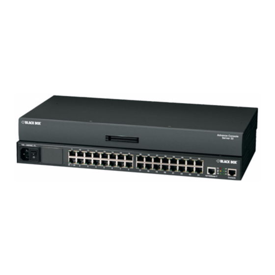
Page 23 Overview The Advanced Console Server is a 1U device that serves as a single access point for using and administering servers and other devices. The following figure shows the front of the CS with its two PCMCIA card slots, and the back of a LS1032A with its Serial, Ethernet, and Console ports. - Page 37 Table 1-1: Model Numbers and Configuration Options Model Number Serial Ports LS1008A LS1016A LS1032A LS1048A The following figure illustrates the BLACK BOX® family of advanced console servers. Figure 1-2: BLACK BOX® CS family of Advanced Console Servers BLACK BOX® CS Installation, Administration, and User’s Guide...
-
Page 38: Connectors On The Black Box® Cs
Introduction Connectors on the BLACK BOX® CS The following figure depicts the connectors on the back of a LS1008A. Ethernet Port Serial Ports Power Supply Console Port Figure 1-3: LS1008A Connectors The number of serial ports and power supplies depends on the model, see table 1-1 for model numbers and configurations options. -
Page 39: Web Manager
IP address before the Web Manager can be accessed through the browser. Following are three ways to find out the dynamically-assigned IP address: BLACK BOX® CS Installation, Administration, and User’s Guide... -
Page 40: Types Of Users
Manager features. Security The Advanced Console Server includes a set of security profiles that consists of predefined parameters to control access to CS and its serial ports. This feature provides more control over the services that are active at any one time. -
Page 41: Authentication
Local authentication is performed only when LDAPDownLocal the LDAP server is down. Authentication is performed locally. For Local example using the /etc/passwd file. Authentication is performed locally first, Local/Radius switching to Radius if unsuccessful. BLACK BOX® CS Installation, Administration, and User’s Guide... - Page 42 Introduction Authentication Type Definition Authentication is performed locally first, Local/TACACS+ switching to TACACS+ if unsuccessful. Authentication is performed locally first, Local/NIS switching to NIS if unsuccessful. NIS authentication is performed. NIS authentication is tried first, switching to NIS/Local Local if unsuccessful. Local authentication is performed only when NISDownLocal the NIS server is down.
-
Page 43: Vpn
The Firewall Configuration form in the Web Manager is structured on two levels: • The view table of the “Firewall Configuration” form which contains a list of chains. • The chains which contain the rules that control filtering. BLACK BOX® CS Installation, Administration, and User’s Guide... -
Page 44: Chain
Introduction Chain A chain is a named profile that includes one or more rules that define the following: • A set of characteristics to look for in a packet • What to do with any packet that has all the defined characteristics The CS filter table contains a number of built-in chains. -
Page 45: Add Rule And Edit Rule Options
For example, if you select DROP as the target action, specify “Inverted” for a source IP address, and do not specify any other criteria in the rule, any BLACK BOX® CS Installation, Administration, and User’s Guide... -
Page 46: Table 1-4: Tcp Protocol Packet Filtering Options
Introduction packets arriving from any other source IP address than the one specified are dropped. Numeric Protocol Options If you select Numeric as the protocol when specifying a rule, you need to specify the desired number. TCP Protocol Options If you select TCP as the protocol when specifying a rule, you can define the following options. -
Page 47: Table 1-5: Udp Protocol Packet Filtering Options
• destination-unreachable • network-unreachable • host-unreachable • protocol-unreachable • port-unreachable • fragmentation-needed • source-route-failed • network-unknown • host-unknown • network-prohibited • host-prohibited • TOS-network-unreachable • TOS-host-unreachable • communication-prohibited • host-precedence violation BLACK BOX® CS Installation, Administration, and User’s Guide... - Page 48 Introduction • precedence-cutoff • source-quench • redirect • network-redirect • host-redirect • TOS-network-redirect • TOS-host-redirect • echo-request • router-advertisement • router-solicitation • time-exceeded • ttl-zero-during-transit • ttl-zero-during-reassembly • parameter-problem • ip-header-bad • required-option-missing • timestamp-request • timestamp-reply • address-mask-request • address-mask-reply Target Actions The “Target”...
-
Page 49: Table 1-6: Log Target Action Options
Includes IP options in the log. IP Options The following list shows the options for the REJECT Target: • icmp-net-unreachable • icmp-host-unreachable • icmp-port-unreachable • icmp-proto-unreachable • icmp-net-prohibited • icmp-host-prohibited • echo-reply • tcp-reset BLACK BOX® CS Installation, Administration, and User’s Guide... -
Page 50: Snmp
Introduction Firewall Configuration Procedures The following table has links to the procedures for defining packet filtering using the Web Manager. To Add a Chain Page 199 To Edit a Chain Page 199 To Add a Rule Page 200 To Edit a Rule Page 201 SNMP The CS administrator can activate Simple Network Management Protocol... -
Page 51: Notifications, Alarms, And Data Buffering
Each syslog server has seven local facility numbers available for its administrator to assign to different devices or groups of devices at different locations. The available facility numbers are Local0 through Local7. BLACK BOX® CS Installation, Administration, and User’s Guide... -
Page 52: Administering Users Of Connected Devices
Introduction An Example of Using Facility Numbers The syslog system administrator sets up a server called “syslogger” to handle log messages from two CS boxes. One CS is located in São Paulo, Brazil, and the other in Fremont, California. The syslog server’s administrator wants to aggregate messages from the São Paulo CS into the facility, and to local1... -
Page 53: Configuring Access To Connected Devices
(IPMI) protocol lets authorized users manage power for servers that have embedded IPMI controllers. IPMI servers do not need to be connected to the CS because their IPMI controllers respond to out-of-band IPMI BLACK BOX® CS Installation, Administration, and User’s Guide... -
Page 54: Configuring Power Management
Introduction commands. Authorized users can also perform IPMI power management of serially-connected devices. The CS uses IPMI V1.5. • Remote power management of devices that are plugged into an IPDU that is connected to CS • The intelligent power distribution unit (IPDU) can be an AlterPath PM connected to any serial port. -
Page 55: Configuring Ports For Power Management By Authorized Users
CS administrators can use the CLI command with the config ipmi options to manage power on IPMI devices while logged into the CS with administrative rights. The ipmitool command is documented in the BLACK BOX® Advanced Console Server Command Reference Guide. BLACK BOX® CS Installation, Administration, and User’s Guide... -
Page 56: Options For Managing Power
Power Management from the CS Command Line CS administrators can use the ipmitool command to manage power on IPMI devices while logged into the CS with administrative rights. The ipmitool command is documented in the BLACK BOX® Advanced Console Server Command Reference Guide. -
Page 57: Chapter 2: Installation And Configuration
Chapter 2 Installation and Configuration This chapter covers the topics listed in the following table. Shipping Box Contents Page 28 Important Pre-Installation Requirements Page 32 Basic Installation Procedures Page 34 Other Methods of Accessing the Web Manager Page 45 Installing PCMCIA Cards Page 46 Connecting AlterPath PM IPDUs Page 47... -
Page 58: Shipping Box Contents
Installation and Configuration Figure 2-1: CS Setup Example Shipping Box Contents The shipping box contains the CS along with the items shown in Table 2-1 and Table 2-2 for CS4 through CS48, and CS1 respectively. The entry for each part provides an illustration, its part number, description, and purpose. You can use checkboxes to check off each item, and you can use the part numbers from this table to reorder any of the parts. - Page 59 CAT5 cable • To connect a device or an IPDU to a serial port. • To connect an Ethernet port to the LAN. • To connect a terminal to a console port. BLACK BOX® CS Installation, Administration, and User’s Guide...
- Page 60 Installation and Configuration Item Description Purpose RJ45 to DB25M Use for modems and other DCE devices. straight-thru cable DB25F Loopback Use to test and diagnose serial ports. 2 - Mounting Use to mount the CS to a rack or cabinet. brackets with 10 - screws (2 spares)
-
Page 61: Table 2-2: Shipping Box Contents For Ls1001A
Use to test and diagnose serial ports. 3.5mm Block Plug Use to establish RS-485 connection. DB9F to DB25M Use to convert serial port connectors. adapter Bumpon Protect Adhesive pads to protect and stabilize CS1. Pads BLACK BOX® CS Installation, Administration, and User’s Guide... -
Page 62: Important Pre-Installation Requirements
Installation and Configuration RJ45 to RJ45 7ft. Use for the following: CAT5 cable • To connect a device or an IPDU to a serial port. • To connect an Ethernet port to the LAN. • To connect a terminal to a console port. DB9F to DB25F To connect the RS-232 serial port to a crossover cable... -
Page 63: Java Plug-In Requirement For Serial Port Access
Check whether the registered Java plug-in is the same as the version you installed. To Install JRE Version 1.4.2 or later and Register the Plug-in 1. Make sure that JRE 1.4.2 or later is installed on the computer. BLACK BOX® CS Installation, Administration, and User’s Guide... -
Page 64: Basic Installation Procedures
Installation and Configuration If needed, download the JRE from http://java.com. The web site automatically checks your configuration and installs the latest version of JRE if one is not available. 2. If JRE is already installed on your system and you just want to activate your browser, do the following steps. -
Page 65: Mounting The Cs
All adapters have an RJ-45 connector on one end and either a DB25 or DB9 male or female connector on the other end. BLACK BOX® CS Installation, Administration, and User’s Guide... -
Page 66: Connecting Servers And Other Devices To Cs
Installation and Configuration To Make an Ethernet Connection 1. Connect the RJ-45 end of the cable to the port labeled “Console” on the 2. Connect the adapter end of the cable to the console port of your server or device. 3. -
Page 67: Making A Direct Connection To Configure The Network Parameters
Do the following procedures in the order shown to avoid problems with components on connected devices. To Power on the CS 1. Make sure the CS’s power switch is off. 2. Plug in the power cable. 3. Turn the CS’s power switch(es) on. BLACK BOX® CS Installation, Administration, and User’s Guide... -
Page 68: Configuring The Network Parameters
Installation and Configuration Note: If your CS model is equipped with dual power supplies, make sure you turn both power switches on. After system initialization, a beep sound may warn if one of the power supplies is off. To Turn Power On Connected Devices •... -
Page 69: To Change The Root Password
Enter a new password when prompted. New password: new_password Re-enter new password: new_password Password changed The following Security Advisory appears the first time CS is powered on, or when the unit is reset to factory default parameters. BLACK BOX® CS Installation, Administration, and User’s Guide... -
Page 70: Figure 2-2: Security Advisory Console Message
Installation and Configuration Figure 2-2: Security Advisory Console Message Important - Security Advisory! Console Management provides critical access to management features of attached equipment. Please take the required precautions to understand the potential impacts this device may have to your SECURITY policies. - Page 71 CS. By default, CS uses the IP address provided by the DHCP server. If your network does not use DHCP, then CS will default to 192.168.160.10. Do you want to use DHCP to automatically assign an IP for your system? (y/n)[y] : BLACK BOX® CS Installation, Administration, and User’s Guide...
- Page 72 Installation and Configuration 5. To change the default static IP address, see your network administrator to obtain a valid IP address. System IP[192.168.160.10]: CS_IP_address 6. Enter the domain name. Domain name[blackbox.com]: domain_name 7. Enter the IP address for the Primary DNS (domain name) server. Primary DNS Server[192.168.44.21] : DNS_server_IP_address 8.
-
Page 73: Selecting A Security Profile Using The Web Manager
For detailed information on Security Profiles see “Security Profiles” on page 226. The administrator can perform the following tasks using the Web Manager. • Administer CS and its connected devices. • Configure user and group permissions. BLACK BOX® CS Installation, Administration, and User’s Guide... -
Page 74: Adding Users And Configuring Ports Using The Web Manager
Installation and Configuration • Access the serial ports and the connected devices. Adding Users and Configuring Ports Using the Web Manager Enabling Ports and Assigning Users. Note: From the factory, CS is configured with all serial ports disabled. • The administrator can add users, enable or disable the serial ports, and select and assign specific users to individual ports. -
Page 75: Other Methods Of Accessing The Web Manager
IP address of that computer to 192.168.160. For example, you could change the computer’s IP address to 192.168.160.44. For the host portion of the IP address, you can use any number except 10, 0, or 255. BLACK BOX® CS Installation, Administration, and User’s Guide... -
Page 76: Installing Pcmcia Cards
Installation and Configuration 2. Bring up a browser on the computer whose address you changed, enter the CS’s default IP address, http://192.168.160.10 to bring up the Web Manager, and log in. Installing PCMCIA Cards The front panel of the CS has two PCMCIA card slots as shown in the following figure. -
Page 77: Connecting Alterpath Pm Ipdus
The following figure shows an CS and two AlterPath PM8 IPDUs daisy- chained. One PM is connected to a serial port on CS configured for power management, and a second PM is daisy-chained from the first PM. BLACK BOX® CS Installation, Administration, and User’s Guide... -
Page 78: Table 2-4: Tasks Related To Connecting Alterpath Pms
Installation and Configuration Figure 2-5: AlterPath PMs Connected to the CS The following table lists the related tasks on connecting IPDU units and managing power. Table 2-4: Tasks Related to Connecting AlterPath PMs Task Where Documented Configure serial ports for power “To Configure a Serial Port for IPDU or management protocol. -
Page 79: Chapter 3: Web Manager For Regular Users
Chapter 3 Web Manager for Regular Users This chapter describes the requirements and the procedures for “Regular Users” to use the Web Manager. Regular users are those who have configured accounts on the CS with limited access rights. Regular users can perform the following tasks using the Web Manager. •... -
Page 80: Figure 3-1: Regular User > Web Manager Login Form
Web Manager for Regular Users The CS administrator can use the Web Manager to configure users and ports. An authorized user can access connected devices through the Web Manager to troubleshoot, maintain, recycle power, and reboot connected devices. Logging in to the Web Manager 1. -
Page 81: Features Of Regular User Forms
The form in the middle changes according to which menu option is selected. The following table illustrates the functions that are common to all the forms. Table 3-1: Common Screen Information Form Area Purpose Click this button to log out. BLACK BOX® CS Installation, Administration, and User’s Guide... -
Page 82: Connect
Web Manager for Regular Users Table 3-1: Common Screen Information (Continued) Form Area Purpose Displays the hostname and IP address assigned during initial configuration, and the model number of the CS. Brings up the online help. Connect When you select the “Connect” option, the following form appears. Figure 3-3: Regular User >... -
Page 83: Connect To Cs
CS followed by the session type, in this case “SSH”. Figure 3-4: Java Applet The following table describes the available buttons in the Java applet: Table 3-2: Java Applet Buttons Button Purpose To send a break to the terminal BLACK BOX® CS Installation, Administration, and User’s Guide... -
Page 84: Connect To Serial Ports
Web Manager for Regular Users Table 3-2: (Continued)Java Applet Buttons Button Purpose To disconnect from the Java applet Select the left icon to reconnect to the server or device; or select the right icon to end the session and disconnect from the Java applet. Connect to Serial Ports The list of serial ports includes the port names or administrator-defined aliases only for ports you have permission to access. -
Page 85: Tcp Port Numbers For Serial Ports
To use Telnet in a shell, enter the following command: telnet hostname | IP_address TCP_port_number To Close a Telnet Session Enter the Telnet hotkey defined for the client. The default is “Ctrl ]” and “q” to quit. BLACK BOX® CS Installation, Administration, and User’s Guide... -
Page 86: Ipdu Power Mgmt
Web Manager for Regular Users To Use SSH to Connect to a Device Through a Serial Port For this procedure, you need the username configured to access the serial port, the TCP port number, and the hostname of the CS or its IP address. •... -
Page 87: Outlets Manager
Figure 3-6: Regular User > Outlets Manager (no permissions) The following form appears if you have permission to manage power on one or more outlets of the AlterPath PM. Figure 3-7: Regular User > Outlets Manager (with permissions) BLACK BOX® CS Installation, Administration, and User’s Guide... -
Page 88: Table 3-4: Regular User > Outlet Management Buttons
Web Manager for Regular Users The form shows separate entries for each serial port configured for power management, a name for the configured serial port if one is defined by the administrator, and the number of IPDUs connected. The matrix displays a line item for each outlet you are authorized to manage. -
Page 89: View Ipdus Info
Whether syslogging has been configured for messages Syslog from this IPDU. Whether a buzzer has been configured to sound when Buzzer a specified alarm threshold is exceeded. Total number of outlets on all connected IPDUs. Number of Outlets BLACK BOX® CS Installation, Administration, and User’s Guide... -
Page 90: Ipdu Multi-Outlet Ctrl
Web Manager for Regular Users Table 3-5: Regular User > Information on the View IPDUs Info Form Description Example Whether over current protection is enabled (to prevent Over Current outlets from being turned on if the current on the Protection IPDU exceeds the specified threshold). -
Page 91: Figure 3-9: Regular User > Ipdu Multi-Outlet (No Permissions)
Figure 3-9: Regular User > IPDU Multi-Outlet (no permissions) The following form appears if you have permission to view and control the outlets that a multi power supply server or device is connected to. BLACK BOX® CS Installation, Administration, and User’s Guide... -
Page 92: Table 3-6: Regular User > Ipdu Multi-Outlet Ctrl. Form Icons
Web Manager for Regular Users Figure 3-10: Regular User > IPDU Multi-Outlet (with permissions) Notice in the above figure that the first line of each group, the light bulb, the lock icon, and the Cycle button operate over the entire group. The light bulb and lock icons next to the individual outlets are used to display the status of each outlet but cannot be used to control the individual outlets. -
Page 93: Security
3. Enter the new password in the “New Password” and the “Repeat New Password” fields. 4. Click OK. 5. Log out and log in using your new password to verify your password change. BLACK BOX® CS Installation, Administration, and User’s Guide... - Page 94 Web Manager for Regular Users...
-
Page 95: Chapter 4: Web Manager For Administrators
This chapter is for system administrators who use the Web Manager to configure the CS and its users. For information on how to configure CS using vi or Command Line Interface (CLI), please consult the BLACK BOX® CS Installation, Administration, and User’s Guide. -
Page 96: Black Box® Web Manager
Web Manager for Administrators BLACK BOX® Web Manager CS administrators perform most tasks through the BLACK BOX® Web Manager either locally or from a remote location. The Web Manager provides a real-time view of the equipment that is connected to the CS. -
Page 97: Common Tasks For Cs Administrators
Configure devices for IPMI power “IPMI Power Management” on page 139 management. Select an authentication method for “Authentication” on page 214 accessing connected devices. Configure packet filtering. “Firewall Configuration” on page 186 BLACK BOX® CS Installation, Administration, and User’s Guide... -
Page 98: Common Features Of Administrator Forms
Web Manager for Administrators Common Features of Administrator Forms The common features of all Web Manager forms for CS administrators are described in the following sections. • Buttons and CS Information • Getting more information Buttons and CS Information The following figure shows the control buttons that display at the bottom of the form when the logged in user is an administrator. -
Page 99: Table 4-3: Administrator > Options For Trying, Saving, And Restoring
Click the “apply changes” If “try changes” has not been previously button clicked, updates the appropriate configuration files. Overwrites the backed up copy of the configuration files. BLACK BOX® CS Installation, Administration, and User’s Guide... -
Page 100: Logging Into The Web Manager
Web Manager for Administrators The following table illustrates the information that displays in the upper right corner of all Web Manager forms. Table 4-4: Administrator > Logout Button and Other Information in the Upper Right Form Area Purpose Click this button to log out. Displays the hostname, IP address assigned during initial configuration, and the model number of the Advanced Console Server. -
Page 101: Figure 4-2: Administrator > Web Manager Login Form
Caution: It is important to change the “root” password as soon as possible to avoid security breaches. If another administrator is already logged in, the dialog box shown in the following screen example appears. BLACK BOX® CS Installation, Administration, and User’s Guide... -
Page 102: Figure 4-3: Administrator > Multi Administrator Login Message
Web Manager for Administrators Figure 4-3: Administrator > Multi Administrator Login Message Click the appropriate radio button and then click Apply. Note: The following Security Advisory appears the first time CS is accessed. Browser’s pop-up blocker should be disabled for this dialog box to appear. -
Page 103: Overview Of Administrative Modes
1. Wizard 2. Expert In Wizard mode, the Expert button displays. In Expert mode, the Wizard button displays. Clicking these buttons toggles between Wizard and Expert mode. Expert is the default mode. BLACK BOX® CS Installation, Administration, and User’s Guide... -
Page 104: Wizard Mode
Web Manager for Administrators Wizard Mode The Wizard mode is designed to simplify the setup and configuration process by guiding the administrator through six configuration steps. When you log in to CS as an administrator or as a user with administrative privileges, by default the system point to Expert Mode>Ports>Ports Status form. -
Page 105: Table 4-5: Administrator > Cs Configuration And Expert Menus
Table 4-5: Administrator > CS Configuration and Expert Menus Chapters Configuring the CS in Wizard Mode Chapter 5 Configuring the CS in Expert Mode Chapter 6 Applications Menu [Expert] Chapter 7 Network Menu [Expert] Chapter 8 BLACK BOX® CS Installation, Administration, and User’s Guide... - Page 106 Web Manager for Administrators Table 4-5: Administrator > CS Configuration and Expert Menus Chapters Security Menu [Expert] Chapter 9 Ports Menu [Expert] Chapter 10 Administration Menu [Expert] Chapter 11...
-
Page 107: Chapter 5: Configuring Cs In Wizard Mode
Chapter 5 Configuring CS in Wizard Mode There are six configuration steps displayed in the menu panel of the Web Manager in Wizard mode. The following table lists the sections where the steps are described. Step 1: Security Profile Page 77 Step 2: Network Settings Page 85 Step 3: Port Profile... -
Page 108: Default Security Profile
Configuring CS in Wizard Mode Note: SSH root access is enabled when the security profile is set to “Moderate” or “Open”. If a “Secured” security profile is selected, you need to switch to a “Custom” security profile, and enable “allow root access” option. 2. -
Page 109: Table 5-1: Wizard > Enabled Services To Access The Cs Under Each
Access to Serial Ports Secure Moderate Open Custom Default Console (Telnet) Console (SSH) Console (Raw) Serial Port Authentication Bidirect (Dynamic Mode Support) 1-The Default security profile parameters are the same as Moderate profile. BLACK BOX® CS Installation, Administration, and User’s Guide... -
Page 110: Table 5-3: Wizard > Enabled Protocols For Each Security Profile Shown With A Check Mark
IPSec 1-The Default security profile parameters are the same as Moderate profile. The first step in configuring your Advanced Console Server is to select a Security Profile. One of the following situations is applicable when you boot the CS unit. -
Page 111: Serial Port Settings And Security Profiles
The following reminder dialog box appears before you proceed to Step2: Network Setting. Figure 5-2: Security and Serial Ports Configuration Alert BLACK BOX® CS Installation, Administration, and User’s Guide... -
Page 112: Figure 5-3: Security Advisory Dialog Box
Configuring CS in Wizard Mode To Select or Configure a Security Profile The following procedure assumes you have installed a new CS at your site, or you have reset the unit to factory default. 1. Enter the assigned IP address of the CS in your browser and login as an administrator. -
Page 113: Figure 5-4: Wizard > Step 1: Security Profile Form
4. Select a pre-defined Security Profile by pressing one of the “Secured”, “Moderate”, “Open”, or “Default” profiles, or create a “Custom” profile. The following dialog box appears when you select the “Custom” profile. BLACK BOX® CS Installation, Administration, and User’s Guide... -
Page 114: Figure 5-5: Custom Security Profile Dialog Box
Configuring CS in Wizard Mode Figure 5-5: Custom Security Profile Dialog Box Caution: Take the required precautions to understand the potential impacts of each individual service configured under the "Custom" profile Refer to Table 5-1 on page 79, and the subsequent tables for a comparison of the available services in each security profile. -
Page 115: Step 2: Network Settings
During initial setup of the CS, the administrator configures the basic network settings that were required to enable logins through the Web Manager. You can skip this step if the current settings are correct. BLACK BOX® CS Installation, Administration, and User’s Guide... -
Page 116: Figure 5-6: Wizard > Step 2: Network Settings - Dhcp Disabled
Configuring CS in Wizard Mode In preparation to configure network settings collect the following information and proceed with the network configuration procedure. • Hostname • An IP address for CS • Domain name • DNS server’s IP address • Gateway IP address •... -
Page 117: Figure 5-7: Wizard > Step 2: Network Settings - Dhcp Enabled
3. Enter the following network information: • Host Name • IP addresses • Network Mask • Domain Name • DNS Server • Gateway IP 4. Select “apply changes” to save configuration to flash. BLACK BOX® CS Installation, Administration, and User’s Guide... -
Page 118: Step 3: Port Profile
Configuring CS in Wizard Mode 5. Select the “Next” button, or proceed to “Step 3: Port Profile”. Step 3: Port Profile Selecting “Step 3: Port Profile” brings up a form for configuring the Console Access Profile (CAS). The protocol used to access the serial ports can be configured in this form. -
Page 119: Table 5-4: Wizard > Serial Port Profile Parameters And Usage
Options range from 5–8 1 [Default] Must match the number of stop bits used Stop Bits by the devices connected to all ports. Options are either 1 or 2 BLACK BOX® CS Installation, Administration, and User’s Guide... -
Page 120: To Set Parameters For All Serial Ports
Configuring CS in Wizard Mode Table 5-4: Wizard > Serial Port Profile Parameters and Usage (Continued) Parameter Options Description Check for enabled. If the “Authentication Required” is Authentication enabled, user authentication is enforced Required Unchecked for disabled. using the local passwd database. [Default] To specify other authentication methods such as RADIUS, TACACS+, LDAP,... -
Page 121: Step 4: Access
“admin” group, enabling them to administer the connected devices without the ability to change the configuration of the CS. By default any user can access any port as long as they have a valid user ID and password. BLACK BOX® CS Installation, Administration, and User’s Guide... -
Page 122: Figure 5-9: Wizard > Step 4:Access
Configuring CS in Wizard Mode Figure 5-9: Wizard > Step 4:Access The Access form lists the currently defined Users and has “Add”, “Change Password”, and “Delete” buttons. In the Users list by default, there is a “root” account that cannot be deleted. The “root”... -
Page 123: Table 5-5: Wizard > Add User Dialog: Field Names And Definitions
Select whether the user of this group is a “NonBio” [Default] or a [dropdown list] “BioUser.” The “BioUser” group should only be selected if authentication will be made through the AlterPath Bio (biometric authentication). BLACK BOX® CS Installation, Administration, and User’s Guide... -
Page 124: Figure 5-11: Wizard > Step 4: Change Password Dialog Box
Configuring CS in Wizard Mode Table 5-5: Wizard > Add User Dialog: Field Names and Definitions Field Name Definition Optional. The default shell when the user makes an SSH or a Telnet Shell connection. Choices are: sh [Default] or bash. Optional notes about the user’s role or configuration. -
Page 125: To Delete A User
For security reasons, change the “root” password from the default “bb” as soon as possible. 1. Select “Step 3: Access.” The “Access” form displays. 2. Select the name of the user whose password you want to change. BLACK BOX® CS Installation, Administration, and User’s Guide... -
Page 126: Step 5: Data Buffering
Configuring CS in Wizard Mode 3. Click “Change Password.” The “Change User Password” dialog box displays. 4. Enter the new password in both fields, and click OK. 5. Click “apply changes.” Step 5: Data Buffering Selecting “Step 5: Data Buffering” brings up a form to allow logging the console data to a data buffer file either locally in CS or remotely to an external storage source such as an NFS server or Syslog server. -
Page 127: Figure 5-13:Wizard > Step 5: Data Buffering [Local]
The following figure shows the form when Data Buffering is set to enabled, and the “Destination” is set to “Local”. Figure 5-13:Wizard > Step 5: Data Buffering [Local] The following figure shows the form when data buffering is set to “Destination Remote” BLACK BOX® CS Installation, Administration, and User’s Guide... -
Page 128: Table 5-6: Wizard > Data Buffering Field Names And Definitions
Configuring CS in Wizard Mode Figure 5-14:Wizard > Step 5: Data Buffering [Remote] The following table provides description for each field whether local or remote destination is selected. Table 5-6: Wizard > Data Buffering Field Names and Definitions Field Name Definition Where the buffer files should be stored. -
Page 129: Table 5-7: Wizard > Differences Between Remote And Local
CS’s flash memory. If needed, you can supplement the flash memory module by installing a flash memory card (with an adapter) or other storage device in a PCMCIA slot. For a list of supported PCMCIA cards see Appendix C. BLACK BOX® CS Installation, Administration, and User’s Guide... -
Page 130: To Configure Data Buffering
Configuring CS in Wizard Mode Note: You can perform advanced configuration in Expert mode including the option of setting up data buffering separately for individual or groups of serial ports. To Configure Data Buffering 1. Select “Step 4: Data Buffering” 2. -
Page 131: Step 6: System Log
Selecting “Step 6: System Log” brings up a form for identifying one or more syslog servers to receive syslog messages generated by the CS’ serial ports. Syslogging for IPDUs is also possible, if IPDU power management is configured. See Chapter 7, “IPDU Power Mgmt. BLACK BOX® CS Installation, Administration, and User’s Guide... -
Page 132: Figure 5-15:Wizard > Step 6: System Log
Configuring CS in Wizard Mode The form appears as shown in the following figure. Figure 5-15:Wizard > Step 6: System Log Note: To configure syslog with data buffering features for specific ports, switch to the Expert Mode, Ports > Physical Ports > Modify Selected Ports > Data Buffering. -
Page 133: Table 5-8: Cs Configuration And Expert Menus Chapters
Table 5-8: CS Configuration and Expert Menus Chapters Configuring the CS in Expert Mode Chapter 6, “Configuring the CS in Expert Mode Applications Menu [Expert] Chapter 7, “Applications Menu & Forms BLACK BOX® CS Installation, Administration, and User’s Guide... - Page 134 Configuring CS in Wizard Mode Table 5-8: CS Configuration and Expert Menus Chapters Network Menu [Expert] Chapter 8, “Network Menu & Forms Security Menu [Expert] Chapter 9, “Security Menu & Forms Ports Menu [Expert] Chapter 10, “Ports Menu & Forms Administration Menu [Expert] Chapter 11, “Administration Menu &...
-
Page 135: Chapter 6: Configuring The Cs In Expert Mode
Chapter 6 Configuring the CS in Expert Mode This chapter provides an overview of configuring the CS Web Manager in Expert Mode. The following chapters in this manual introduces the Expert mode forms and functionality. The Expert mode is designed for the advanced user administrator who needs to configure the CS beyond the capabilities of the basic wizard mode. -
Page 136: Figure 6-1: Expert Mode Screen Elements
Configuring the CS in Expert Mode These forms are identified by their tabs. Select the tab to access the desired form. Top Menu Left Menu Tabs Form Area Command buttons Wizard/Expert Figure 6-1: Expert Mode Screen Elements Note: Procedures in this manual use shortcuts to tell how to get to Web Manager forms. -
Page 137: Mapping Of The Expert Mode Menus And Forms
— Boot Configuration — Data Buffering — Backup Configuration — Multi User — Upgrade Firmware — Power Management — Reboot — Other — Online Help — Virtual Ports — Ports Status — Ports Statistics BLACK BOX® CS Installation, Administration, and User’s Guide... -
Page 138: Description Of Forms In Expert Mode
Configuring the CS in Expert Mode Description of Forms in Expert Mode The following table briefly describes the functionality of each menu and the related forms. For detailed procedures refer to the page where documented for each section. Table 6-2: Expert > Applications Form Use This Form To: Where... -
Page 139: Table 6-3: Expert > Network
Chapter 8, Page 186 Firewall packets should be filtered. Configuration View information about the local Chapter 8, Page 201 Host Table network environment. View table of hosts; create, edit, and delete hosts. BLACK BOX® CS Installation, Administration, and User’s Guide... -
Page 140: Table 6-4: Expert > Security
Configuring the CS in Expert Mode Table 6-3: Expert > Network Menu Selection Use this menu to: Where Documented To manually add routes. Static routes Chapter 8, Page 202 Static Routes are a very quick and effective way to route data from one subnet to different subnets. -
Page 141: Table 6-6: Administration
Configure the alarm strings and the Chapter 11, Page 295 Notifications destination of the notification. CS can send notification by email, pager or SNMP trap in the occurrence of any system warnings and alarms. BLACK BOX® CS Installation, Administration, and User’s Guide... - Page 142 Defines the settings for loading the operating system in the event that the CS fails to boot successfully. The BLACK BOX® CS can boot from its internal firmware or from the network. This section configures the required parameters. Backup Configuration Use a FTP server to save and Chapter 11, Page 310 retrieve your CS configuration;...
- Page 143 Description of Forms in Expert Mode BLACK BOX® CS Installation, Administration, and User’s Guide...
- Page 144 Configuring the CS in Expert Mode...
-
Page 145: Chapter 7: Applications Menu & Forms
Chapter 7 Applications Menu & Forms This Chapter describes the “Applications” menu and the related forms. The following table provides a description of the left menu panel and links to the detailed information and procedures. Table 7-1: Expert > Applications Menu Menu Selection Use this menu to: Where... -
Page 146: Applications
Applications Menu & Forms Table 7-1: Expert > Applications Menu Menu Selection Use this menu to: Where Documented Configure a menu of commands that will be Page 146 Terminal Profile presented to the user when they power on their Menu computer terminal and login to the CS. -
Page 147: Figure 7-2: Expert > Applications > Connect Form
• Connect to CS Clicking the “Connect to CS” radio button and clicking the “Connect” button, brings up a Java applet running an SSH session similar to the following figure. BLACK BOX® CS Installation, Administration, and User’s Guide... -
Page 148: Figure 7-3: Expert > Ssh Session Java Applet
Applications Menu & Forms Figure 7-3: Expert > SSH session Java Applet Note: SSH root access is enabled when the security profile is set to “Moderate” or “Open”. If a “Secured” security profile is selected, you need to switch to a “Custom”... -
Page 149: Figure 7-4: Expert > Serial Port Java Applet
This procedure logs you into the CS as a “Regular User” in a SSH session. 1. Go to Applications > Connect in Expert mode. 2. Click the “Connect to CS” radio button. 3. Click the “Connect” button. BLACK BOX® CS Installation, Administration, and User’s Guide... -
Page 150: Ipdu Power Mgmt
Applications Menu & Forms A Java applet viewer appears. If your security profile is set to “Moderate” or “Open” you receive a “root” prompt, otherwise, an authentication form appears. You cannot authenticate unless you change the security profile to “Custom” and enable “allow root access”. To Connect to a Device Through a Serial Port 1. -
Page 151: Outlets Manager
(in seconds) that the system waits between turning on the currently- selected outlet and the next outlet. • Save the current configuration to Flash memory. The following figure shows an Outlets Manager form. BLACK BOX® CS Installation, Administration, and User’s Guide... -
Page 152: Table 7-2: Expert > Outlets Manager Icons Description
Applications Menu & Forms Figure 7-6: Expert > Applications > IPDU Power Mgmt. > Outlets Manager The following table illustrates what each icon indicates Table 7-2: Expert > Outlets Manager Icons Description Button Purpose Yellow bulbs indicate an outlet is switched on.Gray indicates an outlet is switched off. -
Page 153: Figure 7-7: Expert > Outlets Manager Icons
1. Go to Applications > IPDU Power Mgmt. > Outlets Manager The “Outlets Manager” form appears. 2. To switch an outlet on or off, click the adjacent light bulb. 3. To lock or unlock an outlet, click the adjacent padlock. BLACK BOX® CS Installation, Administration, and User’s Guide... -
Page 154: View Ipdus Info
Applications Menu & Forms 4. To momentarily power an outlet off and then on again, click the adjacent “Cycle” button. 5. To change the outlet’s name or the power up interval, click the adjacent “Edit” button. The Edit Outlet dialog box appears. a. -
Page 155: Table 7-3: Expert > View Ipdus General Information
For example, the configuration illustrated in Figure 7-9 there are two sets of data. Master Unit Information and Slave 1 Information. There are two PM8 15A IPDUs are daisy-chained through Serial Port 1. BLACK BOX® CS Installation, Administration, and User’s Guide... -
Page 156: Table 7-4: Expert > View Ipdus Unit Information
Applications Menu & Forms Table 7-4: Expert > View IPDUs Unit Information Description Example AlterPath PM model number PM8 15A Model AlterPath PM firmware version 1.5.0 Software Version Number of amperes that triggers an alarm or syslog 15.0A Alarm Threshold message if it is reached Current level on the IPDU 0.0A... -
Page 157: Users Manager
Clicking “Add” brings up the following dialog box where you can specify one or more comma-separated user names and one or more outlets. Figure 7-11: Expert > IPDU Power Mgmt. > Users Manager > Add User BLACK BOX® CS Installation, Administration, and User’s Guide... -
Page 158: To Configure Users To Manage Power Outlets On Ipdus
Applications Menu & Forms When a user is added, their name is added to the list on the Users Manager form, as shown in the following figure. To Configure Users to Manage Power Outlets on IPDUs 1. Go to Applications > IPDU Power Mgmt. > Users Manager. The “Users Manager”... -
Page 159: Configuration
IPDU(s). The following figure shows the Configuration form when two AlterPath PMs are connected to Serial port 1 configured for power management. BLACK BOX® CS Installation, Administration, and User’s Guide... -
Page 160: Figure 7-12: Expert > Applications > Ipdu Power Mgmt. > Configuration
Applications Menu & Forms Figure 7-12: Expert > Applications > IPDU Power Mgmt. > Configuration Note: The number of amps shown in the Master Unit (and Slave units if available) pull-down menu varies according to the model of the connected PM. Figure 7- 12 shows number 15 for two 15 amp PMs as a Master and a Slave. -
Page 161: Software Upgrade [For The Alterpath Pm]
/tmp/pmfirmware file is present and the software version it contains is more recent than the installed version, information about the new version is displayed, and an “Update” button appears on the form. BLACK BOX® CS Installation, Administration, and User’s Guide... -
Page 162: To Download Alterpath Pm Software From Black Box
Applications Menu & Forms To Download AlterPath PM Software You can use this procedure to download the AlterPath PM software. 1. On a computer in the same subnet as the CS, bring up a browser and go to http://www.cyclades.com/support/downloads.php 2. Find the section on the downloads page for the AlterPath PM, and compare the latest driver’s version number to the version shown in the Applications >... -
Page 163: Ipdu Multi-Outlet Ctrl
Selecting Applications > IPDU Multi-Outlet Ctrl display the following form used for managing power on a group of outlets that provide power to a multi power supply server or device connected to a serial port. BLACK BOX® CS Installation, Administration, and User’s Guide... -
Page 164: Figure 7-14: Expert > Applications > Ipdu Multi-Outlet Ctrl
Applications Menu & Forms Figure 7-14: Expert > Applications > IPDU Multi-Outlet Ctrl Whether the power supplies are connected to the same PM or not, all outlets that are configured to the same serial port can be treated as a group and controlled simultaneously from this form. -
Page 165: Prerequisites For Multi-Outlet Control
Cycle button operate over the entire group. The light bulb and lock icons next to the individual outlets are used to display the status of each outlet but cannot be used to control the individual outlets. BLACK BOX® CS Installation, Administration, and User’s Guide... -
Page 166: Table 7-5: Expert > Ipdu Multi-Outlet Ctrl Form Icons
Applications Menu & Forms Figure 7-16: Expert > Applications > Multi-Outlet Control Icons The icons in the first line of each group are described in the following table. Table 7-5: Expert > IPDU Multi-Outlet Ctrl form icons Button Purpose A grey light bulb icon indicates that the group is off. A yellow light bulb indicates that the group is on. -
Page 167: To Power On Or Power Off A Group Of Outlets In The Same Power State
2. To power on the group, click the yellow light bulb adjacent to the group name. All of the outlets turns on. 3. To power off the group, do the following steps: BLACK BOX® CS Installation, Administration, and User’s Guide... -
Page 168: To Lock Or Unlock A Group Of Outlets In The Same Power State
Applications Menu & Forms a. Click the yellow light bulb icon adjacent to the group name once to turn all of the outlets off. All of the outlets are in the same state. b. To turn all of the outlets on, click the grey light bulb icon adjacent to the group name. -
Page 169: Ipmi Power Management
“Add” button appears. Figure 7-17:Expert > Applications > IPMI Power Mgmt. When an “Add” button or “Edit” button is pressed, a form appears for adding or editing a device. BLACK BOX® CS Installation, Administration, and User’s Guide... -
Page 170: Figure 7-18: Expert > Ipmi Power Mgmt. "Add/Edit Ipmi Device
Applications Menu & Forms Figure 7-18:Expert > IPMI Power Mgmt. “Add/Edit IPMI Device” Dialog Boxes After you fill out the fields or make changes and save the changes, the device is added to the IPMI Devices list or the configuration for the device is changed. -
Page 171: Table 7-6: Expert > Ipmi Information
Table 7-7: Expert > IPMI Power Mgmt. Form Icons Button Purpose A yellow light bulb indicates the current state of the device. Clicking the light bulb icon toggles the state of the device. BLACK BOX® CS Installation, Administration, and User’s Guide... -
Page 172: To Delete, Add, Or Edit An Ipmi Device To Enable Or Disable Ipmi Power Management
Applications Menu & Forms Button Purpose When the status is unknown, a question mark appears instead of the light bulb. A question mark indicates either of the following conditions. • The device was added or deleted and the changes were not saved. •... -
Page 173: To Manage Power On An Ipmi Device
“Power Management” tab. 3. To enable Power Management of a device connected to the current port and plugged into a connected IPDU, click “Enable Power Management on this port.”. The following form appears. BLACK BOX® CS Installation, Administration, and User’s Guide... -
Page 174: Figure 7-20: Expert > Serial Port > Power Management > Enable
Applications Menu & Forms Figure 7-20: Expert > Serial Port > Power Management > Enable Power Management 4. Click the “Add” button The “Add Outlet” dialog box appears. Figure 7-21: Expert > Power Management Add Outlet Dialog Box 5. Enter the outlet number(s) - separated by comma - into which the device is connected to. -
Page 175: Figure 7-22: Expert > Serial Port > Power Management > User
Figure 7-22: Expert > Serial Port > Power Management > User Permissions 3. Enter a valid username or groupname in the “New User/Group” field, and click “Add.” 4. Click “Done.” 5. Click “apply changes.” BLACK BOX® CS Installation, Administration, and User’s Guide... -
Page 176: Terminal Profile Menu
Applications Menu & Forms To enable IPMI Power Management of an IPMI device connected to the currently-selected port Check the checkbox next to “Enable IPMI on this port.” The “IPMI key” and “IPMI Server” fields appear. Figure 7-23: Expert > Serial Port > Power Management > Enable IPMI 2. -
Page 177: Figure 7-24:Expert > Applications > Terminal Profile Menu
SSH sessions on remote hosts. When you click “Add,” the “Add Option” dialog box appears, as shown in the following figure. Figure 7-25: Expert >Terminal Profile Menu “Add Option” Dialog Box BLACK BOX® CS Installation, Administration, and User’s Guide... -
Page 178: Figure 7-26: Expert > Terminal Profile Menu Example
Applications Menu & Forms For example, you can create a menu called “SSH to Servers” with options that launch SSH connections to several servers, such as the one shown in the following screen example. Figure 7-26: Expert > Terminal Profile Menu Example The command menu then appears when the terminal is powered on. - Page 179 Applications 5. Click “apply changes.” BLACK BOX® CS Installation, Administration, and User’s Guide...
- Page 180 Applications Menu & Forms...
-
Page 181: Chapter 8: Network Menu & Forms
Chapter 8 Network Menu & Forms This Chapter describes the “Network” menu and the related forms. The following table provides a description of the left menu panel and links to the detailed information and procedures. Table 8-1: Expert > Network Menu Menu Selection Use this menu to: Where... -
Page 182: Network
Network Menu & Forms Menu Selection Use this menu to: Where Documented Configure Simple Network Management Page 181 SNMP Protocol (SNMP) with community names, OID and user names. This section and the dialog boxes guide you to configure the required parameters. Firewall Configuration Configure static IP tables, and how packets Page 186 should be filtered. -
Page 183: Table 8-2: Expert > Host Settings Form Fields
The following table provides a brief definition of the Host Settings form fields. Table 8-2: Expert > Host Settings Form Fields Filed Name Field Definition The fully qualified domain name identifying Host Name the specific host computer on the network. BLACK BOX® CS Installation, Administration, and User’s Guide... - Page 184 Network Menu & Forms Table 8-2: Expert > Host Settings Form Fields Filed Name Field Definition A text string designed to appear on the Console Banner console upon logging into and exiting from a port as a way to verify or identify the particular port connection.
-
Page 185: To Configure Host Settings [Expert]
Additional fields appear. 3. Enter the name assigned to the IP address of the CS in the “Host Name” field. 4. Enter a console banner in the “Console Banner” field. BLACK BOX® CS Installation, Administration, and User’s Guide... - Page 186 Network Menu & Forms The console banner appears on the console upon logging into and exiting from a port as a way to verify or identify the particular port connection 5. Under Ethernet Port, complete or edit the following fields, as necessary. a.
-
Page 187: Syslog
You can use the Syslog form to configure how the CS handles system logged messages. The Syslog form allows you to do the following: • Specify one or more syslog servers to receive syslog messages related to ports. • Specify rules for filtering messages. BLACK BOX® CS Installation, Administration, and User’s Guide... -
Page 188: Pcmcia Management
Network Menu & Forms The top field on the form “CAS Ports Facility” is used to tell CS where to send syslog messages. • You can specify a facility number for the messages from serial ports. Obtain the facility numbers from the syslog server’s administrator. •... -
Page 189: Figure 8-4: Expert > Network > Pcmcia Management
Note: CS supports GPRS and 1xRTT PCMCIA cards through a Generic Dial-Out application. For Configuration details refer to the CS Command Reference Guide, Chapter 7, Section 7.3 “Generic Dial-Out”. BLACK BOX® CS Installation, Administration, and User’s Guide... -
Page 190: To Configure A Pcmcia Card
Network Menu & Forms To Configure a PCMCIA Card 1. Go to Network > PCMCIA Management. The PCMCIA Management form appears. 2. Insert the card into the PCMCIA slot on the front of the CS and Click the “Insert” button for the slot in which you installed the PCMCIA card. The following dialog box appears. -
Page 191: Configuring A Modem Pcmcia Card
You can use the “PCMCIA Management” form under “Network” to enable a remote user to call into the CS through an installed modem PCMCIA card. When you select Modem from the pull-down menu, the dialog box shown in the following figure appears. BLACK BOX® CS Installation, Administration, and User’s Guide... -
Page 192: Table 8-3: Expert > Form Fields For A Modem Card
Network Menu & Forms Figure 8-5: Expert > PCMCIA Modem Card Configuration Dialog Box The following table provides a brief description of the fields available in the Modem dialog box. Table 8-3: Expert > Form Fields for a Modem Card Field Name Definition Pull-down menu to select the type of PCMCIA... -
Page 193: Figure 8-6: Expert > Pcmcia Modem Card Configuration Dialog Box -Ppp
If you enable “Call Back”, the Phone Number field appears on the Slot dialog box, as shown in the following figure. Figure 8-7: Expert > Modem PCMCIA Card Configuration Dialog Box - Call Back BLACK BOX® CS Installation, Administration, and User’s Guide... -
Page 194: Configuring An Isdn Pcmcia Card
Network Menu & Forms To Configure a Modem PCMCIA Card 1. Install the modem card and select “Modem” from the pull-down menu on the PCMCIA Management form. 2. To enable PPP, do the following steps: a. Check the PPP checkbox. b. -
Page 195: Table 8-4: Expert > Form Fields For An Isdn Card
1. Install the ISDN card and select “ISDN” from the pull-down menu on the PCMCIA Management form. The “Local IP” and “Remote IP” fields and the “Call Back” check box appear on the Slot dialog box. BLACK BOX® CS Installation, Administration, and User’s Guide... -
Page 196: Configuring A Gsm Pcmcia Card
Network Menu & Forms 2. Enter an IP address in the “Local IP” field, if desired. By default, the IP address of the CS is used. Only change the IP address if you have a specific reason to do so. 3. -
Page 197: Figure 8-9: Expert > Gsm Pcmcia Card Configuration Dialog
Figure 8-9: Expert > GSM PCMCIA Card Configuration Dialog Box When the “Call Back” checkbox is checked, the Phone Number field appears as shown in the following figure. Figure 8-10: Expert > GSM PCMCIA Card Configuration Dialog Box - Call Back BLACK BOX® CS Installation, Administration, and User’s Guide... -
Page 198: Table 8-5: Expert > Form Fields For A Gsm Card
Network Menu & Forms The following table provides a brief description of the fields available in the GSM dialog box. Table 8-5: Expert > Form Fields For a GSM Card Field Name Definition Select GSM from the pull-down menu. [PCMCIA Card] The local IP address of the PCMCIA card. -
Page 199: Configuring An Ethernet Pcmcia Card
Ethernet dialog box Form Fields for an Ethernet Card Table 8-6: Expert > Field Name Definition Select Ethernet from the Pull-down menu. [PCMCIA Card] The local IP address of the Ethernet. IP Address BLACK BOX® CS Installation, Administration, and User’s Guide... -
Page 200: Configuring A Pcmcia Compact Flash Card Or A Pcmcia Hard Disk Drive
Network Menu & Forms Field Name Definition The network address of the Ethernet. Network Address To Configure an Ethernet PCMCIA Card 1. Install the Ethernet card and select “Ethernet” from the pull-down menu on the PCMCIA Management form. The “IP Address” and “Network Mask” fields appear on the Slot dialog box. -
Page 201: Table 8-7: Expert > Form Fields For A Compact Flash/Hard Disk
To Configure a Compact Flash PCMCIA Card or a PCMCIA Hard Disk Drive 1. Install the compact flash card or the hard disk drive and select “Compact Flash/Hard Disk” from the pull-down menu on the PCMCIA Management form. BLACK BOX® CS Installation, Administration, and User’s Guide... -
Page 202: Configuring A Wireless Lan Pcmcia Card
Network Menu & Forms The “Enable” checkbox appears on the Slot dialog box. 2. Click the “Enable” checkbox. The “Use for data buffering” checkbox appear on the Slot dialog box. 3. If desired, uncheck the “Use for data buffering” checkbox. Default is checked. -
Page 203: Table 8-8: Expert > Form Fields For A Wireless Lan Card
5. In the “Channel” field, enter a channel number. 6. Click the “Encrypted” checkbox, if an encrypted data communication is required. 7. Enter a unique key for decoding the encrypted data. 8. Click OK. 9. Click “apply changes.” BLACK BOX® CS Installation, Administration, and User’s Guide... -
Page 204: Configuring A Cdma Pcmcia Card
Network Menu & Forms Configuring a CDMA PCMCIA Card You can use the “PCMCIA Management” form under “Network” to configure a CDMA PCMCIA card. When you select “CDMA” from the pull-down menu, the dialog box shown in the following figure appears. Figure 8-14: Expert >... -
Page 205: To Configure A Cdma Pcmcia Card
The “Phone Number” field appears on the Slot dialog box. b. Enter a number for the CS to use to call back the CDMA card. 7. Click OK. 8. Click “apply changes.” BLACK BOX® CS Installation, Administration, and User’s Guide... -
Page 206: Ejecting A Pcmcia Card
Network Menu & Forms Ejecting a PCMCIA Card Use the “Eject” button on the PCMCIA management form to eject any PCMCIA card before physically ejecting it. Any other method can cause a kernel panic. To Eject a PCMCIA Card From the Card Slot 1. -
Page 207: Figure 8-15: Expert > Network > Vpn Connections
When you click the “Edit” or “Add” buttons, a “New/Modify Connection” form appears, as shown in the following figure. The form displays different fields depending on whether “RSA Public Keys” or “Shared Secret” are selected. BLACK BOX® CS Installation, Administration, and User’s Guide... -
Page 208: Figure 8-16: Expert > Vpn "New/Modify Connection" Dialog Box
Network Menu & Forms Figure 8-16: Expert > VPN “New/Modify Connection” Dialog Box The remote gateway is referred to as the Remote or “Right” host, and the CS is referred to as the Local or “Left” host. If left and right are not directly connected, then you must also specify a “NextHop”... -
Page 209: Table 8-10: Expert > Field And Menu Options For Configuring A Vpn
You can use copy and paste Keys is selected) to enter the key in the “RSA Key” field. Pre-shared password between left and right users. Pre-Shared Secret (If “Shared Secret” is selected) BLACK BOX® CS Installation, Administration, and User’s Guide... -
Page 210: To Configure Vpn
Network Menu & Forms Field Name Definition The boot action configured for the host, either Ignore, Add, Boot Action Start. To Configure VPN To enable VPN, make sure that IPSec is enabled through the security profile section. 1. Go to Network > VPN Connections. The VPN Connections form appears. -
Page 211: Snmp
ID (OID), and permission (read-write or read-only). SNMP v3 requires: user name, password, OID, and permission. Selecting Network > SNMP brings up the form shown in the following figure. BLACK BOX® CS Installation, Administration, and User’s Guide... -
Page 212: Figure 8-17: Expert > Network > Snmp
Network Menu & Forms Figure 8-17: Expert > Network > SNMP You can use this form to enable notifications about significant events or traps from CS to an SNMP management application, such as HP Openview, Novell NMS, IBM NetView, or Sun Net Manager. The following table explains the required parameters to complete the SNMP form and the associated dialog boxes. -
Page 213: Table 8-11: Expert > Fields And Menu Options For Snmp
SNMP v3 only. User Name and Password Clicking the “Add” or “Edit” buttons under “SNMPv1/SNMPv2 Configuration” brings up the “New/Mod SNMP v1 v2 Configuration” dialog box, as shown in the following figure. BLACK BOX® CS Installation, Administration, and User’s Guide... -
Page 214: Figure 8-18: Expert > "New/Mod Snmp V1 V2 Configuration
Network Menu & Forms Figure 8-18: Expert > “New/Mod SNMP v1 v2 Configuration” Dialog Box Clicking the “Add” or “Edit” buttons under “SNMPv3 Configuration” brings up the “New/Mod SNMP v3 Configuration” dialog box, as shown in the following figure. Figure 8-19:Expert > “New/Mod SNMP v3 Configuration” Dialog Box To Configure SNMP 1. - Page 215 Note: In addition to SNMP configuration described in this section, you need to make sure SNMP service is enabled and configured for one or more serial ports in order to send SNMP traps. The related tasks are listed in the following table. BLACK BOX® CS Installation, Administration, and User’s Guide...
-
Page 216: Firewall Configuration
Network Menu & Forms Table 8-12: Expert > Tasks for Configuring SNMP Task Where Documented To configure one or more serial See “SNMP Trap Notifications Entry” on page 302 ports to send SNMP traps. Firewall Configuration Firewall configuration, also known as IP filtering, refers to the selective blocking of the passage of IP packets between global and local networks. -
Page 217: Figure 8-21: Expert > Firewall Configuration "Edit Chain" Dialog
Only the policy can be edited for a default chain. The options are “ACCEPT,” and “DROP.” Note: User-defined chains cannot be edited. If a user-defined chain is selected for editing, the message shown in the following figure appears. BLACK BOX® CS Installation, Administration, and User’s Guide... -
Page 218: Figure 8-22:Firewall Configuration "User-Defined Chain" Message
Network Menu & Forms Figure 8-22:Firewall Configuration “User-defined Chain” Message “Delete” Button If one of the user-defined chains is selected and the “Delete” button is pressed the chain is deleted. Note: Default chains cannot be deleted. If one of the default chains is selected and the “Delete”... -
Page 219: Figure 8-24: Expert > Firewall Configuration "Add Chain" Dialog
The example shows the OUTPUT chain selected for editing. Figure 8-25: Firewall Configuration “Edit Rules for chain_name” Form The buttons shown in the following figure appear at the bottom of the form. BLACK BOX® CS Installation, Administration, and User’s Guide... -
Page 220: Figure 8-26: Firewall Configuration "Edit Rules For Chain_Name
Network Menu & Forms Figure 8-26:Firewall Configuration “Edit Rules for chain_name” Buttons • Pressing the “Add” button opens the “Add Rule” dialog box. • Selecting a “Rule” and pressing the “Edit” button opens the “Edit Rule” dialog box. • Selecting a rule and pressing the “Up” and “Down” buttons moves the rule up and down the list. -
Page 221: Figure 8-28: Firewall Configuration "Add Rule" And "Edit Rule
The source and destination IP and related fields are shown in the following figure. Figure 8-29:Firewall Configuration “Add Rule” and “Edit Rule” Source and Destination IP and Mask Fields BLACK BOX® CS Installation, Administration, and User’s Guide... -
Page 222: Figure 8-30:Firewall Configuration "Add Rule" And "Edit Rule" Protocol Menu Options
Network Menu & Forms Protocol You can select a protocol for filtering. The “Protocol” pull-down menu is shown in the following figure. Figure 8-30:Firewall Configuration “Add Rule” and “Edit Rule” Protocol Menu Options The additional fields that appear for each protocol are explained in the following sections. -
Page 223: Table 8-13: Expert > Tcp Options Fields
UDP Protocol Fields If UDP is selected as a protocol when specifying a rule, the additional fields shown in the following figure appear at the bottom of the form. BLACK BOX® CS Installation, Administration, and User’s Guide... -
Page 224: Table 8-14: Expert > Udp Options Fields
Network Menu & Forms Figure 8-33:Firewall Configuration “Add Rule” and “Edit Rule” UDP Protocol Fields The following table defines the fields in the UDP Options Section. Table 8-14: Expert > UDP Options Fields Field Definition A port number for filtering in the “Source Port” or “Destination Source Port Port”... -
Page 225: Figure 8-34:Firewall Configuration "Add Rule" And "Edit Rule" Icmp Type Menu Options
Network Figure 8-34:Firewall Configuration “Add Rule” and “Edit Rule” ICMP Type Menu Options BLACK BOX® CS Installation, Administration, and User’s Guide... -
Page 226: Table 8-15: Expert > Firewall Configuration Input And Output Interface, And Fragments Fields Definitions
Network Menu & Forms Input Interface, Output Interface, and Fragments If an interface (such as eth0 or eth1) is entered in the “Input Interface” field, incoming packets are filtered for the specified interface. If an interface is entered in the “Output Interface” field, outgoing packets are filtered for the specified interface. -
Page 227: Table 8-16: Expert > Target Log Options Selection Fields
The prefix is included in the log entry. Log Prefix Includes the TCP sequence in the log. TCP Sequence Includes TCP options in the log. TCP Options Includes IP options in the log. IP Options BLACK BOX® CS Installation, Administration, and User’s Guide... -
Page 228: Table 8-17: Expert > Reject Options Sections
Network Menu & Forms REJECT Target If REJECT is selected from the Target pull-down menu, the following pull- down menu appears Figure 8-37:Firewall Configuration “Add Rule” and “Edit Rule” REJECT Target Menu Options Any “Reject with” option causes the input packet to be dropped and a reply packet of the specified type to be sent. -
Page 229: To Add A Chain
4. Finish defining the chain by adding one or more rules, as described in "To Add a Rule" To Edit a Chain Perform this procedure if you want to change the policy for a default chain. BLACK BOX® CS Installation, Administration, and User’s Guide... -
Page 230: To Add A Rule
Network Menu & Forms Note: User-defined chains cannot be edited. If you want to rename a chain you added, delete it and create a new one. 1. Go to Network > Firewall Configuration 2. Select one of the default chains from Chain list, and then click the “Edit” button. -
Page 231: Host Table
The Host Table form enables you to keep a table of host names and IP addresses that comprise your local network, and provide information on your environment. Selecting Network > Host Tables brings up the form shown in the following figure. BLACK BOX® CS Installation, Administration, and User’s Guide... -
Page 232: Static Routes
Network Menu & Forms Figure 8-38: Expert > Network > Host Tables To Define the CS’s IP Address and Hostname 1. Go to Network > Host Tables The Host Tables form appears. 2. To edit a host, select the host IP address from the list and click the “Edit” button. -
Page 233: Figure 8-39: Expert > Network > Static Routes
Figure 8-40: Expert > Static Routes “Add” and “Edit” Dialog Boxes - Default Route The example shows the fields and menus that appear when the “Default” route type is selected from the “Route” pull-down menu. BLACK BOX® CS Installation, Administration, and User’s Guide... -
Page 234: Figure 8-41: Expert > Static Routes "Add" And "Edit" Dialog Boxes
Network Menu & Forms The following figure shows the fields and menus that appear when the “Network” route type is selected from the “Route” pull-down menu. Figure 8-41: Expert > Static Routes “Add” and “Edit” Dialog Boxes - Network Route The following figure shows the fields and menus that appear when the “Host”... -
Page 235: Table 8-18: Expert > Fields And Menus For Configuring Static Routes
• To add a static route, select the “Add” button from the form. The system invokes the “New/Modify Route” dialog box. 2. Choose “Default”, “Network”, or “Host” from the “Route” pull-down menu. BLACK BOX® CS Installation, Administration, and User’s Guide... - Page 236 Network Menu & Forms 3. If you selected “Network, do the following steps. a. Enter the IP address of the destination network in the “Network IP” field. b. Enter the netmask of the destination network in the “Network Mask” field. 4.
-
Page 237: Chapter 9: Security Menu & Forms
Chapter 9 Security Menu & Forms This Chapter describes the “Security” menu and the related forms. The following table provides a description of the left menu panel and links to the detailed information and procedures. Table 9-1: Expert > Security Menu Menu Selection Use this menu to: Where Documented... -
Page 238: Users And Groups
Security Menu & Forms Users and Groups Users and Groups form allows you to do the following tasks: • Set up user access to the CS Web Manager • Assign users to specific groups that share common access rights • Assign or change passwords •... -
Page 239: Adding A User
The password associated with the user name. Group On the Group pull-down menu, select “Regular User [Default]” or “Admin.” Note: To configure a user to be able to perform all administrative functions, select the “Admin” group. BLACK BOX® CS Installation, Administration, and User’s Guide... -
Page 240: Adding A Group
Security Menu & Forms Table 9-2: Expert > Add User Dialog Field Names and Definitions Field Name Definition Shell Optional. The default shell is /bin/sh when the user makes an SSH or Telnet connection. Comments Optional notes about the user’s role or configuration. Adding a Group If you click the “Add”... -
Page 241: To Delete A User Or Group
4. Enter the new password in the “New Password” field and enter it again in the “Repeat New Password” field. 5. Click OK. 6. Click “apply changes.” To Add a Group 1. Go to Security > Users and Groups BLACK BOX® CS Installation, Administration, and User’s Guide... -
Page 242: Active Ports Sessions
Security Menu & Forms The Users & Groups form displays. 2. Under the list of groups, click “Add.” The “Add Group” dialog box displays. 3. Enter the name for the new group in the “Group Name” field. 4. Enter one user name or multiple comma-separated user names in the “Users”... -
Page 243: Table 9-3: Expert > Active Ports Sessions Information
Where the network connection is from. From Login time in hours and minutes. If login was not on the Login same day, the date of login also appears. How long since last activity. Idle BLACK BOX® CS Installation, Administration, and User’s Guide... -
Page 244: Authentication
Security Menu & Forms Field Name Definition The amount of CPU time consumed by all active processes JCPU including currently running background jobs. The amount of CPU time consumed by the current PCPU process. Name of the current process. What To View, Kill, or Refresh Active User Sessions 1. -
Page 245: Configuring Authentication For Cs Logins
Configuring Authentication for CS Logins The default authentication method for CS is Local. You can either accept the default or select another authentication method from the “Unit Authentication” pull-down menu on the AuthType form. BLACK BOX® CS Installation, Administration, and User’s Guide... -
Page 246: Configuring Authentication Servers For Logins To Cs And Connected Devices
Security Menu & Forms Figure 9-6: Expert > Security > Authentication > AuthType Form Any authentication method selected for CS is used for authentication of any user attempting to log into the CS through Telnet, SSH, or the Web Manager. To Configure the CS Login Authentication Method 1. -
Page 247: Table 9-4: Tasks For Setting Up Authentication Servers
219 LDAP LDAP, LDAP/Local, or See “To Configure an LDAPDownLocal LDAP Authentication Server” on page 221 Kerberos Kerberos, Kerberos/Local, or See “To Configure a KerberosDownLocal Kerberos Authentication Server” on page 223 BLACK BOX® CS Installation, Administration, and User’s Guide... -
Page 248: Figure 9-7: Expert > Security > Authentication > Radius
Security Menu & Forms Table 9-4: Tasks for Setting up Authentication Servers. Method Variations Procedures NIS, Local/NIS, NIS/Local, or See “To Configure a NIS NISDownLocal Authentication Server” on page 225 To Configure a RADIUS Authentication Server Perform the following procedure to configure a RADIUS authentication server when CS or any of its ports are configured to use RADIUS authentication method or any of its variations (Local/RADIUS, RADIUS/ Local, or RADIUS/DownLocal). -
Page 249: Figure 9-8: Expert > Security > Authentication > Tacacs
Local, or TACACS+/DownLocal). Go to Security > Authentication > TACACS+ in Expert mode. The TACACS+ form appears as shown in the following figure. Figure 9-8: Expert > Security > Authentication > TACACS+ BLACK BOX® CS Installation, Administration, and User’s Guide... -
Page 250: Group Authorization On Tacacs
Security Menu & Forms Fill in the form according to your local TACACS+ server configuration. To apply “Authorization” in addition to authentication to the box and ports, select the “Enable Raccess Authorization” check box. By default “Raccess Authorization” is disabled, and no additional authorization is implemented. -
Page 251: To Configure An Ldap Authentication Server
1. Go to Security > Authentication > LDAP in Expert mode. The “LDAP” form displays with “LDAP Server” and “LDAP Base” fields filled in from with the current values in the /etc/ldap.conf file. BLACK BOX® CS Installation, Administration, and User’s Guide... -
Page 252: Figure 9-9: Expert > Security > Authentication > Ldap
Security Menu & Forms Figure 9-9: Expert > Security > Authentication > LDAP 2. Supply the IP address of the LDAP server in the “LDAP Server” field. 3. If the LDAP authentication server uses a different distinguished name for the search base than the one displayed in the “LDAP Base” field, change the definition. -
Page 253: To Configure A Kerberos Authentication Server
Add an entry for CS if none exists and an entry for the Kerberos server. Click “Add.” The “New/Modify Host” dialog appears. ii. Enter the address in the “IP Address” field. iii. Enter the name in the “Name” field. BLACK BOX® CS Installation, Administration, and User’s Guide... -
Page 254: Figure 9-10: Expert > Administration > Time/Date
Security Menu & Forms iv. Enter an optional alias in the “Alias” field. 2. Make sure that time, date, and timezone settings are synchronized on the CS and on the Kerberos server. Note: Kerberos authentication depends on time synchronization. Time and date synchronization can be achieved by setting both CS and the Kerberos server to use the same NTP server. -
Page 255: Figure 9-11: Expert > Security > Authentication > Kerberos
CS or any of its ports is configured to use NIS authentication method or any of its variations (Local/NIS, NIS/Local, or NISDownLocal). 1. Go to Security > Authentication > NIS in Expert mode. The NIS form displays as shown in the following figure. BLACK BOX® CS Installation, Administration, and User’s Guide... -
Page 256: Security Profiles
Security Menu & Forms Figure 9-12:Expert > Security > Authentication > NIS 2. Fill in the form according to your configuration of the NIS server. 3. Click “apply changes.” Security Profiles Selecting Security > Security Profile brings up the form shown in the following figure. -
Page 257: Pre-Defined Security Profiles
The Custom Security Profile opens up a dialog box to allow custom configuration of individual protocols or services. Note: By default, a number of protocols and services are enabled in the Custom profile, however, they are configurable to user’s custom requirements. BLACK BOX® CS Installation, Administration, and User’s Guide... -
Page 258: Table 9-5: Expert > Enabled Services To Access The Cs Under Each
Security Menu & Forms The following tables illustrate the properties for each of the Security Profiles. The enabled services in each profile is designated with a check mark. Table 9-5: Expert > Enabled services to access the CS under each security profile. Access to CS Secure Moderate... -
Page 259: Table 9-7: Expert > Enabled Protocols For Each Security Profile Shown With A Check Mark
IPSec 1-The Default security profile parameters is the same as Moderate profile. The first step in configuring your Advanced Console Server is to define a Security Profile. One of the following situations is applicable when you boot up the CS unit. -
Page 260: Serial Port Settings And Security Profiles
Security Menu & Forms Serial Port Settings and Security Profiles All serial ports on CS units shipped from the factory are disabled by default. The administrator can enable ports individually or collectively and assign specific users to individual ports. The following figure shows the default factory settings of serial ports. Figure 9-14: Expert >... -
Page 261: Figure 9-16:Serial Ports Protocol Incompatibility Dialog Box
1. Enter the assigned IP address of the CS in your browser and login as an administrator. The following security warning dialog box appears. BLACK BOX® CS Installation, Administration, and User’s Guide... -
Page 262: Figure 9-17: Security Advisory Dialog Box
Security Menu & Forms Figure 9-17: Security Advisory Dialog Box Note: Your browser’s pop-up blocker should be disabled for this dialog box to appear. 2. Review the Security Advisory and click the “Close” button. 3. The Web Manager is redirected to Wizard > Step 1: Security Profile The following form is displayed. -
Page 263: Figure 9-18:Wizard > Step 1: Security Profile Form
4. Select a pre-defined Security Profile by pressing one of the “Secured”, “Moderate”, “Open”, or “Default” profiles, or create a “Custom” profile. The following dialog box appears when you select the “Custom” profile. BLACK BOX® CS Installation, Administration, and User’s Guide... -
Page 264: Figure 9-19: Custom Security Profile Dialog Box
Security Menu & Forms Figure 9-19: Custom Security Profile Dialog Box Caution: Take the required precautions to understand the potential impacts of each individual service configured under the "Custom" profile. Refer to Table 9-5 on page 228, and the subsequent tables for a comparison of the available services in each security profile. -
Page 265: Table 9-8: Configuring Cs In Expert Mode
Configure Users and Groups “Users and Groups” on page 208 Configure Serial Ports “Physical Ports” on page 239 Configure Network Settings “Host Settings” on page 152 Configure IPDU Power Management “IPDU Power Mgmt.” on page BLACK BOX® CS Installation, Administration, and User’s Guide... -
Page 266: Security Certificates
Security Menu & Forms Security Certificates CS generates its own self-signed SSL certificate for HTTPS using OpenSSL. Note: It is highly recommended that you use the “openssl” tool to replace the CS generated certificate. Certificate for HTTP Security A certificate for HTTP security is created by a CA (Certificate Authority). Certificates are most commonly obtained through generating public and private keys using a public key algorithm like RSA or X.509. -
Page 267: Chapter 10: Ports Menu & Forms
Chapter 10 Ports Menu & Forms This Chapter describes the “Ports” menu and the related forms. The following table provides a description of the left menu panel in the Web Manager and links to the detailed information and procedures. Table 10-1: Expert > Ports Menu Menu Selection Use this menu to: Where Documented... -
Page 268: Figure 10-1: Expert > Ports
Ports Menu & Forms Menu Selection Use this menu to: Where Documented View information on the data Page 288 Ports Statistics reception (Rx bytes) and transmission (Tx bytes) on each physical port. View current CAS user(s), Baud rate, frame, parity, break, and overruns. -
Page 269: Physical Ports
“Modify Selected Ports” button, and set values for an individual or a group of ports. Selecting “Modify Selected Ports” or “Modify All Ports” option brings up a form with the following six BLACK BOX® CS Installation, Administration, and User’s Guide... -
Page 270: Figure 10-3: Expert > Ports > Physical Ports > "Modify
Ports Menu & Forms tabs Figure 10-3: Expert > Ports > Physical Ports > “Modify ..Ports ” Tab Options To Select One or More Serial Ports Go to Ports > Physical Ports in Expert mode The Physical Ports form appears. To select a port or ports, do one of the following steps. -
Page 271: General
Under Ports > Physical Ports in Expert Mode, if you select one or more ports from the ports list and click the Modify button, the General form appears as shown in the following form. BLACK BOX® CS Installation, Administration, and User’s Guide... -
Page 272: Connection Profiles
Ports Menu & Forms Figure 10-4: Expert > Ports > Physical Ports > General Form The General form allows you to define general port settings, connect to an IPDU port, and select the connection type to a serial port (SSH, Telnet, or both). -
Page 273: Console Access Server (Cas) Profile Connection Protocols
Terminal Server (TS) Profile Connection Protocols When a computer terminal is connected to the console port on a device, a Terminal Server (TS) profile must be defined for the serial port. BLACK BOX® CS Installation, Administration, and User’s Guide... -
Page 274: Table 10-3: Expert > Terminal Server (Ts) Connected Protocols
Ports Menu & Forms Selecting the appropriate connection protocol on the Ports > Physical Ports > General form is part of defining the TS profile. You can configure serial ports to support computer terminals in the following two ways: • Dedicate a terminal to access a single remote server by means of either Telnet, SSHv1, SSHv2, or Raw Socket connections. -
Page 275: Bidirectional Telnet Protocol
The timeout period can be configured through the Web Manager Ports > Physical Ports > Access form. The administrator can build custom menus using the “Terminal Profile Menu” form accessible from Web Manager, Applications > Terminal Profile Menu, or BLACK BOX® CS Installation, Administration, and User’s Guide... -
Page 276: Modem And Power Management Connection Protocols
Ports Menu & Forms from a terminal window using the command. You should menush_cfg specify the bidirectional shell command, in the Web Manager, /bin/menush Ports > Physical Ports > Access form. Modem and Power Management Connection Protocols The following table shows the connection protocols for modems or AlterPath PM IPDUs connected to the serial ports. -
Page 277: Figure 10-5: Expert > Ports > Physical Ports > Console Connection
3. To change the connection protocol, select one of the options from the “Connection Protocol” pull-down menu: Console (Telnet), Console (SSH), Console (Telnet & SSH), or Console (Raw). The default is Console (Telnet). BLACK BOX® CS Installation, Administration, and User’s Guide... -
Page 278: Figure 10-7:Connection Protocols > Console
Ports Menu & Forms Figure 10-7:Connection Protocols > Console 4. If you want to change any of the other current settings, see "To Configure Serial Port Settings to Match the connected devices" on page 257. 5. To further configure the serial port’s connection protocol: •... -
Page 279: Figure 10-9: Expert > Ports > Physical Ports > Bidirectional Telnet Connection
Figure 10-9: Expert > Ports > Physical Ports > Bidirectional Telnet Connection 3. To change the connection protocol, select Bidirectional Telnet from the “Connection Protocol” pull-down men. Figure 10-10: Connection Protocols > Bidirectional Telnet BLACK BOX® CS Installation, Administration, and User’s Guide... -
Page 280: Figure 10-11: Expert > Ports > Physical Ports > Terminal Server Active
Ports Menu & Forms 4. If you want to change any of the other current settings, see "To Configure Serial Port Settings to Match the connected devices" on page 257. 5. Go to “Access” tab and configure the following settings: •... -
Page 281: Figure 10-12: Expert > Ports > Physical Ports > Terminal Server
Figure 10-12: Expert > Ports > Physical Ports > Terminal Server Connection 3. To change the connection protocol, select a Terminal Server connection from the “Connection Protocol” pull-down men, “Telnet”, “SSHv1”, “SSHv2”, “Local Terminal”, or “Raw Socket”. Figure 10-13:Connection Protocols > Terminal Server BLACK BOX® CS Installation, Administration, and User’s Guide... -
Page 282: Figure 10-14: Expert > Ports > Physical Ports > Modem Connection
Ports Menu & Forms 4. To configure a terminal to automatically connect to CS, do the following steps. a. Select “Local Terminal” from the “Connection Protocol” pull-down menu. b. Define a terminal profile menu. “Terminal Profile Menu” form is at Expert >... -
Page 283: Figure 10-16: Connection Protocols > Modem
Figure 10-15: Expert > Ports > Physical Ports > Modem Connection 3. To change the connection protocol, select one of the options from the “Connection Protocol” pull-down menu: “PPP-No Auth.”, “PPP”, “SLIP”, or “CSLIP”. Figure 10-16: Connection Protocols > Modem BLACK BOX® CS Installation, Administration, and User’s Guide... -
Page 284: Figure 10-17: Expert > Ports > Physical Ports > Power Management
Ports Menu & Forms 4. If you want to change any of the other current settings, see "To Configure Serial Port Settings to Match the connected devices" on page 257. 5. To further configure the serial port’s connection protocol: • For user access and authentication methods, see "Access"... -
Page 285: Figure 10-18: Expert > Ports > Physical Ports > Power Management Connection
3. To change the connection protocol, select “Power Management” from the “Connection Protocol” pull-down menu. Figure 10-19: Connection Protocols > Power Management 4. Enter a desired name for the IPDU in the “Alias” field. BLACK BOX® CS Installation, Administration, and User’s Guide... -
Page 286: Figure 10-20: Access > Authentication Types
Ports Menu & Forms 5. Select an access method to the IPDU from the “Allow Access by” drop- down menu. The options are SSH, Telnet, or SSH and Telnet. Selecting an access option activates the “Access” and “Other” tabs. 6. Go to “Access” tab. a. -
Page 287: To Associate An Alias To A Serial Port
The settings for a serial port must match the connection settings on the connected device. 1. Go to Ports > Physical Ports in Expert mode, and select a port or ports to modify. The General form appears. BLACK BOX® CS Installation, Administration, and User’s Guide... -
Page 288: Figure 10-21: Expert > Ports > Physical Ports > Serial Port Settings
Ports Menu & Forms Figure 10-21: Expert > Ports > Physical Ports > Serial Port Settings 2. To change the baud rate, select an option from 2400 to 921600 Kbps from the Baud Rate pull-down menu. The default is 9600, which is the most common baud rate for serially- managed devices. -
Page 289: Access
Under Ports > Physical Ports in Expert Mode, after you select one or more serial ports, and click the Modify Port(s), select the Access form from the tabbed menu. The following form appears. Figure 10-22:Expert > Ports > Physical Ports > Access Form BLACK BOX® CS Installation, Administration, and User’s Guide... -
Page 290: Table 10-5: Expert > Access Form Fields
Ports Menu & Forms The following table describes the menu and fields on the Access form. Table 10-5: Expert > Access Form Fields Field Description Authorized Users/Groups Restrict or deny access to a serial port by specifying one or more users or groups. You can deny access to one or more users or groups by entering an exclamation point (!) before the user or group name. -
Page 291: Authentication Methods And Fallback Mechanism
Kerberos, LDAP, RADIUS, or TACACS+, the user can get access denial if either the authentication server is down, or it does not authenticate him/her. An authentication fallback mechanism can be BLACK BOX® CS Installation, Administration, and User’s Guide... -
Page 292: Table 10-6: Expert > Authentication Methods
Ports Menu & Forms defined in case the first authentication level fails. See the following table on authentication methods and fallback mechanisms. Table 10-6: Expert > Authentication Methods Authentication Type Definition No authentication. None Authentication is performed using a Kerberos Kerberos server. -
Page 293: To Configure A Serial Port Login Authentication Method
3. To select an authentication method, select one of the options in the Type menu. 4. Click “Done.” 5. Click “apply changes.” The changes are stored in /etc/portslave/pslave.conf on CS. 6. Make sure that an authentication server is specified for the selected authentication type. BLACK BOX® CS Installation, Administration, and User’s Guide... -
Page 294: Data Buffering
Ports Menu & Forms The following table lists the procedures that apply to each authentication method. Table 10-7: Expert > Procedures to Configure an Authentication Server Authentication Method Where Documented "To Configure a Kerberos Authentication Kerberos, Kerberos/Local, or Kerberos/ Server" on page 223. DownLocal "To Configure an LDAP Authentication LDAP, LDAP/Local, or LDAP/DownLocal... -
Page 295: Table 10-8: Expert > Data Buffering Form Fields
The following table describes the fields available in the data buffering form. Table 10-8: Expert > Data Buffering Form Fields Field Name Definition Destination Location for the data files. Either “Local” or “Remote” BLACK BOX® CS Installation, Administration, and User’s Guide... - Page 296 Ports Menu & Forms Table 10-8: Expert > Data Buffering Form Fields Field Name Definition Mode (Local Destination) circular or linear. In circular mode, data is written into the specified local data file until the upper limit on the file size is reached;...
-
Page 297: To Configure Data Buffering For Serial Ports
Click the checkbox next to “Record the timestamp in the data buffering file” to specify whether to include a timestamp with the data. e. From the “Show Menu” pull-down menu, choose among the following options: • Show all options • BLACK BOX® CS Installation, Administration, and User’s Guide... -
Page 298: Multi User
Ports Menu & Forms • Show data buffering file only • Show without the erase options 4. If you checked “Buffer to Syslog,” perform the following steps. a. Enter the IP address of the syslog server in the “Syslog Server” field. b. -
Page 299: Table 10-9: Expert > Multi User Form Fields
Allow sniffing on multiple user connection to a Sniff Mode serial port. Users with access rights to a multi user shared Privilege Users session. The hotkey for accessing the menu. Menu Hotkey BLACK BOX® CS Installation, Administration, and User’s Guide... -
Page 300: Table 10-10: Expert > Options On The "Allow Multiple Sessions" Menu
Ports Menu & Forms Field Name Definition Checkbox to enable notify users of session Notify Users access. The following table describes the options from the “Allow Multiple Sessions” pull-down menu. Table 10-10: Expert > Options on the “Allow Multiple Sessions” Menu Menu Option Description Do not allow multiple sessions. -
Page 301: Power Management
Modify Port(s), you can select the Power Management form from the tabbed menu. The following form appears. Figure 10-26:Expert > Ports > Physical Ports > Power Management BLACK BOX® CS Installation, Administration, and User’s Guide... -
Page 302: Table 10-11: Expert > Power Management Form Fields
Ports Menu & Forms You can use this form to make it possible for a user who is connected to a device through the selected serial port to perform power management. While connected to the device, the user brings up a power management menu or dialog box by entering a hot key. - Page 303 New User/Group (available only if “Allow Users/ Groups” radio button is selected) View list box of authorized users or groups. Allowed Users/Groups (available only if “Allow Users/ Groups” radio button is selected) BLACK BOX® CS Installation, Administration, and User’s Guide...
-
Page 304: Figure 10-28: Expert > Ports > Physical Ports > Power Management > Add Outlets Dialog Box
Ports Menu & Forms Power management while connected to a port is possible only when one or both of the following conditions are true. • The device connected to CS is plugged into an AlterPath PM IPDU and is configured for power management. •... - Page 305 The administrator of the device connected to this serial port uses this hot key to bring up the IPMI power management screen. c. Select the name of the IPMI device from the “IPMI Server” pull- down menu. BLACK BOX® CS Installation, Administration, and User’s Guide...
-
Page 306: Figure 10-29: Expert > Ports > Physical Ports > Power Management>Allow All Users
Ports Menu & Forms 4. Click “Done.” 5. Click “apply changes.” To Configure a User for IPDU Power Management While Connected To a Serial Port Perform this procedure to allow a user to perform power management on a device while connected to it through one of the CS’s serial ports. 1. -
Page 307: Other
Figure 10-31:Expert > Ports > Physical Ports > Other Form You can use this form to configure other settings. The options on this form may be less common settings. The following table describes the available fields in the “Other” form. BLACK BOX® CS Installation, Administration, and User’s Guide... -
Page 308: Table 10-12: Expert > Ports > Physical Ports > Other Form Fields
Ports Menu & Forms Table 10-12: Expert > Ports > Physical Ports > Other Form Fields Field Name Definition The TCP Port number for a serial port. TCP Port The TCP port numbers by default start from 7001 and increment by +1 up to the number of serial ports that the CS unit has. -
Page 309: To Configure Tcp Port Number, Stty Options, Break Interval, And The Login Banner For A Serial Port Connected To A Console
Break Interval, and the Login Banner for a Serial Port Connected to a Console 1. Go to Ports > Physical Ports in Expert mode, and select a port or ports to modify. 2. Select the “Other” tab. BLACK BOX® CS Installation, Administration, and User’s Guide... -
Page 310: To Configure Terminal Server Connection Options
Ports Menu & Forms 3. To change the port number for the serial port, enter another number in the “TCP Port” field. 4. To assign a name to the port’s IP address, enter an alias in the “Port IP Alias” field. (Console connection protocol only) 5. -
Page 311: Virtual Ports
11. Enter the type of terminal in the “Terminal Type” field. 12. Click “Done.” 13. Click “apply changes.” Virtual Ports When Virtual Ports is selected under Ports > Virtual Ports in Expert mode, the following form appears. BLACK BOX® CS Installation, Administration, and User’s Guide... -
Page 312: Figure 10-32: Expert > Ports > Virtual Ports
Ports Menu & Forms Figure 10-32: Expert > Ports > Virtual Ports The virtual ports form allows you to perform clustering of CS units. The CS clustering is designed to allow a large number of serial ports (up to 1024) to be configured and virtually accessed through one IP address. -
Page 313: Table 10-13: Expert > New/Modify Port Dialog Box Fields
The “First Local Port Number” is then 17. The IP address for the master CS or it can Local IP be the global IP address of the cluster in the network. BLACK BOX® CS Installation, Administration, and User’s Guide... - Page 314 Ports Menu & Forms Field Name Definition The first TCP port number for the First Local TCP Port No. slave. For example, if the master unit has 16 ports, the allocated TCP port numbers to the master are 7001-7016. The “First Local TCP Port No.” is then 7017.
-
Page 315: Figure 10-34: Expert > Applications > Connect > Serial Pull-Down
2. From the drop-down menu select the number of ports that you want to assign as slaves. Choices are 1, 4, 8, 16, 32 and 48. 3. Enter the “First Local Port Number”. BLACK BOX® CS Installation, Administration, and User’s Guide... -
Page 316: To Assign Names To Slave Ports In The Cluster
Ports Menu & Forms This is the first port number on the master, after the last port number on the master. 4. Enter the “Local IP” address. This is the IP address of the master. 5. Enter the “First Local TCP Port Number”. This is the first TCP port number on the master, after the last port number on the master. -
Page 317: Ports Status
CS units and the connected devices on your network. Ports Status Selecting Ports > Port Status in Expert mode, brings up the following read- only form, which displays tabular serial port status information. BLACK BOX® CS Installation, Administration, and User’s Guide... -
Page 318: Ports Statistics
Ports Menu & Forms Figure 10-37: Expert > Ports > Ports Status (Read-Only) The information in the following table is available in the Ports Status read- only form. All users have access to this form. The information on this page gets updated when you click the “Refresh”... -
Page 319: Table 10-15: Expert > Ports>Port Status Read-Only Form
The measure of how fast data is moving Baud Rate between devices. Data transmitted. Tx Bytes Data received. Rx Bytes A formatted packet of data usually associated Frame with the Data-Link layer. BLACK BOX® CS Installation, Administration, and User’s Guide... - Page 320 Ports Menu & Forms Column Name Description Error checking bit appended to a data packet. Parity A method of checking the accuracy of transmitted characters. Parity is usually not used, but can be odd or even. A None parity means that data has not exchanged. An out-of-band signal on an RS-232 serial Break port that involves making the Tx data line...
-
Page 321: Chapter 11: Administration Menu & Forms
Chapter 11 Administration Menu & Forms This Chapter describes the “Administration” menu and the related forms. The following table provides a description of the left menu panel links to the detailed information and procedures. Table 11-1: Expert > Administration Menu Menu Selection Use this menu to: Where Documented... -
Page 322: System Information
Administration Menu & Forms Menu Selection Use this menu to: Where Documented Configure CS to boot from its Page 307 Boot Configuration internal firmware or from the network. This section defines the settings for loading the operating system in the event that the CS fails to boot successfully. -
Page 323: Figure 11-1: Expert > Administration > System Information
Figure 11-1: Expert > Administration > System Information You can use the form to view the information shown in the following table. BLACK BOX® CS Installation, Administration, and User’s Guide... -
Page 324: Table 11-2: System Information
Administration Menu & Forms Table 11-2: System Information Parameters Information • Kernel Version System • Current Date • Up Time • Power Supply State • CPU Type • Clock Speed • Revision • Bogomips • MemTotal Memory • MemFree • Buffers •... -
Page 325: Notifications
1. Go to Administration > System Information in Expert mode. The System Information form appears. 2. To view all the information scroll down the form. Notifications Selecting Administration > Notifications in Expert mode brings up the following form. BLACK BOX® CS Installation, Administration, and User’s Guide... -
Page 326: Table 11-3: Expert > Notifications Form Fields
Administration Menu & Forms Figure 11-2: Expert > Administration > Notifications You can use this form to set up alarm notifications about system issues, problems, or other events of interest that occur on the devices that are connected to the serial ports. You can configure notifications to be sent to users through email, pager or SNMP traps. -
Page 327: Email Notifications Entry
Serial Ports Alarm Notification Email Notifications Entry When you go to Administration > Notifications, select “Email” from the pull- down menu, and click on “Add” or “Edit” button the following dialog box appears. BLACK BOX® CS Installation, Administration, and User’s Guide... -
Page 328: Table 11-4: Expert > Email Notifications Dialog Box Fields
Administration Menu & Forms Figure 11-3: Expert > Administration > Notifications > Email > Add/Edit Dialog box The following table describes the available fields in the email notification entry dialog box. Table 11-4: Expert > Email Notifications Dialog Box Fields Field Name Definition The trigger expression used to generate an... -
Page 329: To Configure A Trigger For Email Notification For Serial Ports
8. Enter or change the SMTP server’s IP address in the “SMTP Server” field. 9. Enter or change the SMTP port number in the “SMTP Port” field. 10. Click “OK.” 11. Click “apply changes.” BLACK BOX® CS Installation, Administration, and User’s Guide... -
Page 330: Pager Notifications Entry
Administration Menu & Forms Pager Notifications Entry When you go to Administration > Notifications, select “Pager” from the pull- down menu, and click on “Add” or “Edit” button the following dialog box appears. Figure 11-4: Expert > Administration > Notifications > Pager > Add/Edit Dialog box... -
Page 331: Table 11-5: Expert > Pager Notifications Dialog Box
3. If you need to edit an existing notification select it from the drop-down list and proceed. 4. Enter or change the pager number in the “Pager Number” field. 5. Enter or edit the text that describes the event in the “Text” field. BLACK BOX® CS Installation, Administration, and User’s Guide... -
Page 332: Snmp Trap Notifications Entry
Administration Menu & Forms 6. Enter or change the Short Message Services (SMS) username, the SMS server’s IP address or name, and the SMS port number in the “SMS User Name,” “SMS Server,” and “SMS Port” fields respectively. 7. Click “OK.” 8. -
Page 333: Table 11-6: Expert > Snmp Trap Notifications Dialog Box
• Authentication Failure • EGP Neighbor Loss • Enterprise Specific The password used to authenticate the traps. Community The IP address of the server running the Server SNMP. The content of the notification. Body BLACK BOX® CS Installation, Administration, and User’s Guide... -
Page 334: Serial Ports Alarm Notification
Administration Menu & Forms To Configure a Trigger for SNMP Trap Notification for Serial Ports 1. Go to Administration > Notifications in Expert mode, select SNMP Trap from the pull-down menu. If desired, enable “Notification Alarm for Data Buffering” for an alarm to sound when the trigger action occurs; and click either Add or Edit. -
Page 335: Time/Date
Enabling Network Time Protocol (NTP) synchronizes the CS’s system clock with an NTP server, which maintains the true time (the average of many high-accuracy clocks around the world). If you enable the “Network Time Protocol”, the following form appears. BLACK BOX® CS Installation, Administration, and User’s Guide... -
Page 336: Setting Time And Date With Ntp
Administration Menu & Forms Figure 11-7: Expert > Administration > Time/Date > NTP Enable Setting Time and Date with NTP NTP (Network Time Protocol) is an Internet standard protocol which enables your system clock to be synchronized with the true time, defined as the average of many high-accuracy clocks around the world. -
Page 337: Boot Configuration
An upgraded CS boot image file must be available on the TFTP or BOOTP server. • CS must be configured with a fixed IP address. • The boot filename and the IP address of the TFTP or BOOTP server is known. BLACK BOX® CS Installation, Administration, and User’s Guide... -
Page 338: Table 11-7: Expert > Boot Configuration Form Fields
Administration Menu & Forms The following table describes the boot configuration form fields. Table 11-7: Expert > Boot Configuration Form Fields Field Name Definition A fixed IP address or a DHCP assigned IP IP Address assigned address to the CS unit. to Ethernet Whether the watchdog timer is active or Watchdog Timer... -
Page 339: To Configure Cs Boot
Choose an Ethernet speed from the “Fast Ethernet” pull-down menu. f. Specify the maximum number of packets that the CPU handles before an interrupt in the “Fast Ethernet Max. Interrupt Events” field. BLACK BOX® CS Installation, Administration, and User’s Guide... -
Page 340: Backup Configuration
Administration Menu & Forms 8. Click “apply changes.” Backup Configuration Selecting Administration > Backup Config in Expert mode brings up the form shown in the following figure. Figure 11-9: Expert > Administration > Backup Config The “Type” pull-down menu options on this form are “FTP” and “Storage Device.”... -
Page 341: Table 11-8: Expert > Backup Config Type Ftp Form Fields And
Saves the configuration Load Downloads a previously saved copy of the configuration file from the selected device. When “Storage Device” is selected from the “Type” pull-down menu , the following form appears. BLACK BOX® CS Installation, Administration, and User’s Guide... -
Page 342: Table 11-9: Expert > Backup Config Type Storage Device Form
Administration Menu & Forms Figure 11-10: Expert > Administration > Backup Config > Storage Device The following table describes the available fields when “Storage Device” is selected from the “Type” drop-down menu. Table 11-9: Expert > Backup Config Type Storage Device Form Field Name Definition The system saves the configuration in the storage... -
Page 343: Upgrade Firmware
8. Click “apply changes” 9. Reboot the system. See Administration > Reboot for details, if needed. Upgrade Firmware Selecting Administration > Upgrade Firmware in Expert mode brings up the form shown in the following figure. BLACK BOX® CS Installation, Administration, and User’s Guide... -
Page 344: Table 11-10: Expert > Upgrade Firmware Form Fields
Kernel, applications, and configuration files. The firmware is upgradeable using an FTP server. You can upgrade the firmware directly through BLACK BOX®’ FTP site at ftp://ftp.blackbox.com/lan/ Term-Servers/, or download the new firmware to a local FTP server and upgrade from there. -
Page 345: To Upgrade The Cs's Firmware
Definition Name The URL of the FTP server where the firmware is located. This can be a FTP Site local FTP server, or the BLACK BOX®’ FTP site at ftp://ftp.blackbox.com/lan/Term-Servers/ Username recognized by the ftp server. Username Password associated with the username for the ftp server. -
Page 346: Reboot
Administration Menu & Forms Reboot Selecting Administration > Reboot in Expert mode brings up the form shown in the following figure. Figure 11-12: Expert > Administration > Reboot Clicking the “Reboot” button reboots the CS. To Reboot the CS 1. Go to Administration > Reboot in Expert mode. 2. -
Page 347: Online Help
Figure 11-13:Expert > Administration > Online Help BLACK BOX® host the online-help on an FTP server accessible from the Internet. The path to the BLACK BOX® FTP server is configured by default on CS and is viewable in the “Online Help Path” field as http:// www.blackbox.com/. - Page 348 Administration Menu & Forms 3. In the “Online Help Path” field configure the path to the location of the documenation on your local server. Note: When a directory path is ended with a “/”, the firmware appends the product name and verison. For example, http://www.myserver.com/online-help/ would be http://www.myserver.com/online-help/cs/<firmware version>...
-
Page 349: Appendix A: Technical Specifications
Appendix A Technical Specifications The following table lists the Advanced Console Server hardware specifications MPC855T (PowerPC Dual-CPU) Memory 128MB DIMM SDRAM / 16MB CompactFlash Interfaces 1 Ethernet 10/100BT on RJ45 1 RS232 Console on RJ45 RS232 Serial Ports on RJ45 PCMCIA slots supporting: Secondary Ethernet, Wireless networking, CDMA, GPRS, GSM, V.90 modems, ISDN. - Page 350 Technical Specifications Certification FCC Part 15, A EN55022, A (CE) EN55024 UL 1950 Solaris Ready™...
-
Page 351: Formation
Appendix B Safety, Regulatory, and Compliance Information The following Safety Information for Advanced Console Server are described in this appendix. Safety Guidelines for Rack-Mounting the CS Page 321 Safety Precautions for Operating the CS Page 322 Working inside the BLACK BOX® CS... -
Page 352: Safety Precautions For Operating The Advanced Console Server
Safety, Regulatory, and Compliance Information Temperature The manufacturer's maximum recommended ambient temperature for the Advanced Console Server is 122 ºF (50 ºC). Elevated Operating Ambient Temperature If the CS is installed in a closed or multi-unit rack assembly, the operating ambient temperature of the rack environment may be greater than room ambient temperature. - Page 353 Host Server equipment. Caution: To help prevent electric shock, plug the Advanced Console Server into a properly grounded power source. The cable is equipped with a three-prong plug to help ensure proper grounding.
-
Page 354: Working Inside The Advanced Console Server
18 AWG. Working inside the Advanced Console Server Do not attempt to service the CS yourself, except when following instructions from BLACK BOX® Technical Support personnel. In the latter case, first take the following precautions: 1. Turn the CS off. -
Page 355: Fcc Warning Statement
Herstellers. FCC Warning Statement The Advanced Console Server has been tested and found to comply with the limits for Class A digital devices, pursuant to Part 15 of the FCC rules. These limits are designed to provide reasonable protection against harmful interference when the equipment is operated in a commercial environment. -
Page 356: Aviso De Precaución S-Mark Argentina
Por favor de leer todos los avisos de precaución como medida preventiva para el operador y el Advanced Console Server. Caution: No hacer funcionar el Advanced Console Server con la tapa abierta. Caution: Para prevenir un corto circuito en el Advanced Console Server al desconectarlo de la red, primero desconectar el cable del equipo y luego el cable que conecta a la red. -
Page 357: Trabajar Dentro Del Advanced Console Server
2 amperes, con conductor de 0.75 mm (18 AWG). Trabajar dentro del Advanced Console Server No intente dar servicio al Advanced Console Server, solo que este bajo la dirección de Soporte Técnico de BLACK BOX®. Si este es el caso, tome las siguientes precauciones: Apague el Advanced Console Server. - Page 358 Safety, Regulatory, and Compliance Information...
-
Page 359: Appendix C Supported Pcmcia Cards
Appendix C Supported PCMCIA Cards BLACK BOX® CS supports the PCMCIA cards listed in the table below. Note that some PCMCIA cards have been discontinued by their manufacturers and are marked accordingly. Table C-1: Supported PCMCIA Cards Brand Model 10BT Ethernet... - Page 360 Supported PCMCIA Cards Table C-1: Supported PCMCIA Cards Brand Model 10/100BT Ethernet& V.90 (56k) Modem Combo Xircom XEM5600 10/100BT Ethernet and 56k V.90 modem combination (Discontinued) 802.11b Wireless Ethernet Proxim ORiNOCO 11b Client PC Gold Card - 8410-WD (Discontinued) Linksys Instant Wireless Network PC Card - WPC11 Ver.3 Fiber Optic Danpex...
- Page 361 WARNING: Consult your local GSM service provider for coverage areas and support of this card prior to use with the BLACK BOX® CS. In order to load a Compact Flash card on the BLACK BOX® CS, use a PCMCIA Compact Flash adapter.
- Page 362 Supported PCMCIA Cards...
-
Page 363: Glossary
Glossary Authentication The process by which a user’s identity is checked within the network to ensure that the user has access to the requested resources. Basic In/Out System Chips on the motherboard of a computer contain read only (BIOS) memory instructions that are used to start up a computer. The operating system of a PC also makes use of BIOS instructions and settings to access hardware components such as a disk drive. - Page 364 Glossary BogoMips BogoMips (from "bogus" and MIPS). Unscientific measurement of CPU speed made by the Linux kernel when it boots to calibrate an internal busy-loop. Bonding (Linux) Ability to detect communication failure transparently, and switch from one LAN connection to another. The Linux bonding driver has the ability to detect link failure and reroute network traffic around a failed link in a manner transparent to the application.
- Page 365 BLACK BOX® products run the Linux operating system. Administrators type "CLI" on the command line of the Linux shell. The BLACK BOX® CLI tool provides many commands and nested parameters in a format called the CLI parameter tree.
- Page 366 Glossary Console Terminal used to configure network devices at boot (start-up) time. Also used to refer to the keyboard, video and mouse user interface to a server. Console Port Most of the equipment in a data center (servers, routers, switches, UPS, PBX, etc.) has a serial console port for out-of- band management purposes.
- Page 367 Flash refers to a type of memory that can be erased and reprogrammed in units of memory known as blocks rather than one byte at a time; thus, making updating to memory easier. BLACK BOX® CS Installation, Administration, and User’s Guide...
- Page 368 Glossary Flow Control A method of controlling the amount of data that two devices exchange. In data communications, flow control prevents one modem from "flooding" the other with data. If data comes in faster than it can be processed, the receiving side stores the data in a buffer.
- Page 369 The ticket is then embedded in messages to identify the sender of the message. BLACK BOX® CS Installation, Administration, and User’s Guide...
- Page 370 Glossary After a client and server has used Kerberos to prove their identity, they can also encrypt all of their communications to assure privacy and data integrity as they go about their business. LDAP Lightweight Directory Access Protocol. A software protocol for enabling anyone to locate organizations, individuals, and other resources such as files and devices in a network, whether on the Internet or on a corporate intranet.
- Page 371 Internet protocol address Network masks divide IP addresses into two parts (network address and address of a particular host within the network). Mask have the same form as IP addresses (i.e. BLACK BOX® CS Installation, Administration, and User’s Guide...
- Page 372 Glossary 255.255.255.0), however, its value is needed to be understood as a 32-bit number with certain number of ones on the left end and zeros as the rest. The mask cannot have an arbitrary value. The primary function of a subnet mask is to define the number of IP hosts that participate in an IP subnet.
- Page 373 Even - Parity bit set so that there is an even number of 1 bits None - Parity bit is ignored, value is indeterminate PCMCIA Personal Computer Memory Card International Association. An organization consisting of some 500 companies that has BLACK BOX® CS Installation, Administration, and User’s Guide...
- Page 374 Glossary developed a standard for small, credit card-sized devices, called PC Cards. Originally designed for adding memory to portable computers, the PCMCIA standard has been expanded several times and is now suitable for many types of devices including network cards (NICs). The PCMCIA 2.1 Standard was published in 1993.
- Page 375 SMTP server on another computer. SNMP Short for Simple Network Management Protocol, a set of protocols for managing complex networks. The first versions of SNMP were developed in the early 80s. SNMP works by BLACK BOX® CS Installation, Administration, and User’s Guide...
- Page 376 Glossary sending messages, called protocol data units (PDUs), to different parts of a network. SNMP-compliant devices, called agents, store data about themselves in Management Information Bases (MIBs) and return this data to the SNMP requesters. (Source: Webopedia) SNMP Traps Notifications or Event Reports are occurrences of Events in a Managed system, sent to a list of managers configured to receive Events for that managed system.
- Page 377 Terminal Server A terminal server has one Ethernet LAN port and many RS-232 serial ports. It is used to connect many terminals to the network. Because they have the same physical interfaces, BLACK BOX® CS Installation, Administration, and User’s Guide...
- Page 378 Glossary terminal servers are sometimes used as console access servers. 1. In Unix, refers to any terminal; sometimes used to refer to the particular terminal controlling a given job (it is also the name of a Unix command which outputs the name of the current controlling terminal).
- Page 379 (or reload) button in a Web browser if a Web site does not fully load after a certain length of time following the entry of a Uniform Resource Locator (URL). BLACK BOX® CS Installation, Administration, and User’s Guide...
- Page 380 Glossary...
-
Page 381: Index
Index administrator forms, common features of administrators, web manager for Advanced Console Server, working inside access 79, 228 allow SSH root alarm root notification SSH root notification, serial ports access requirements, port 60, 126 threshold access server trigger (CAS) profile, console... - Page 382 CD, documentation bidirectionlogin timeout CDMA bidirectionshell command CDMA PCMCIA cards, configuring biometric authentication Certificate for HTTP Security BIOS certification, NEBS Black Box CS, connectors on the chain BogoMips channel 155, 334 bonding checksum boot action boot configuration CLI, configuring ports for power...
- Page 383 (TS) profile connection name connection profiles connections, vpn 48, 282 daisy-chain connectors on the Black Box CS 21, 264 data buffering console Destination BLACK BOX® CS Installation, Administration, and User’s Guide...
- Page 384 Index File Size ESSID 308, 337 Local files Ethernet Mode Ethernet PCMCIA cards, configuring NFS File Path events, data buffering off-line Expert mode Remote server configuring CS in 99, 266 time stamp menus and forms mapping data size data buffering events default IPaddress default, security profile destination...
- Page 385 IPsec 79, 228 http 8, 339 ISDN 79, 228 http redirection to https ISDN PCMCIA cards, configuring 79, 228 https Java plug-in 80, 229, 338 ICMP JCPU ICMP protocol icons, power management BLACK BOX® CS Installation, Administration, and User’s Guide...
- Page 386 Index 181, management information base (MIB) 56, 120 management, IPDU power 278, 347 keep-alive interval, TCP mapping, Expert mode menus and forms 11, 224, 262, 339 Kerberos masquerading 11, 217, 262 Kerberos/local master 11, 217, 262 Kerberosdownlocal maximum detected key, IPMI menu &...
- Page 387 TCP port configuring compact flash trap configuring Ethernet configuring GSM configuring ISDN configuring modem configuring wireless LAN ejecting object identifiers (OID) installing off-line data buffering PCMCIA management 183, 343 PCPU OID, object identifiers BLACK BOX® CS Installation, Administration, and User’s Guide...
- Page 388 Index PCPU processing time powermgmt port 162, 246, 344 physical ports planning access to connected devices ppp-no auth plug-in, Java pre-installation requirements PM IPDUs, connecting AltherPath prerequisites for port logging to syslog servers destination multi-outlet control 9, 66 powermgmt using the web manager source pre-shared secret primary IP...
- Page 389 RX bytes (SNMP) slave SLIP 299, 345 SMTP sniff mode 20, 80, 181, 229 SNMP safety precautions SNMP trap notification secure shell (SSH) SNMP trap notifications secure shell, SSH BLACK BOX® CS Installation, Administration, and User’s Guide...
- Page 390 Index SNMP traps SNMP, simple network management protocol table, host SNMPv1 table, routing SNMPv2 TACACS SSH (secure shell) 217, 263, 347 TACACS+ SSH root access TACACS+/downlocal 79, 228 SSH root access, allow 12, 217, 263 TACACS+/local SSH, console 12, 263 TACACS+downlocal SSH, secure shell 79, 228, 244...
- Page 391 LAN PCMCIA cards, configuring administering assigning wiz command privilege wizard mode types of Wizard mode, configuring CS in users and groups working inside the Advanced Console Server users manager users/groups, authorized BLACK BOX® CS Installation, Administration, and User’s Guide...
- Page 392 Index X.509 Cerfiticate on SSH...
Need help?
Do you have a question about the Advanced Console Server and is the answer not in the manual?
Questions and answers