Table of Contents
Advertisement
Modbus Hardened Serial Server
Connect Modbus networks (RS-232, RS-422,
or RS-485) to Ethernet networks, allowing
the Modbus network to become a node
on the network.
Access the Modbus network over a LAN/WAN using direct IP mode
connections.
Order toll-free in the U.S.: Call 877-877-BBOX (outside U.S. call 724-746-5500)
Customer
FREE technical support 24 hours a day, 7 days a week: Call 724-746-5500 or fax 724-746-0746
Support
Mailing address: Black Box Corporation, 1000 Park Drive, Lawrence, PA 15055-1018
Information
Web site: www.blackbox.com • E-mail: info@blackbox.com
BLACK BOX
LES431A
®
Advertisement
Table of Contents

Related Manuals for Black Box LES431A


Summary of Contents for Black Box LES431A
- Page 1 Order toll-free in the U.S.: Call 877-877-BBOX (outside U.S. call 724-746-5500) Customer FREE technical support 24 hours a day, 7 days a week: Call 724-746-5500 or fax 724-746-0746 Support Mailing address: Black Box Corporation, 1000 Park Drive, Lawrence, PA 15055-1018 Information Web site: www.blackbox.com • E-mail: info@blackbox.com...
- Page 2 Trademarks Used in this Manual Trademarks Used in this Manual Black Box and the Double Diamond logo are registered trademarks of BB Technologies, Inc. Firefox is a registered trademark of Mozilla Foundation. Internet Explorer, Windows, and Windows Vista are registered trademarks of Microsoft Corporation.
- Page 3 FCC and IC RFI Statements Federal Communications Commission and Industry Canada Radio Frequency Interference Statements This equipment generates, uses, and can radiate radio-frequency energy, and if not installed and used properly, that is, in strict accordance with the manufacturer’s instructions, may cause inter ference to radio communication. It has been tested and found to comply with the limits for a Class A computing device in accordance with the specifications in Subpart B of Part 15 of FCC rules, which are designed to provide reasonable protection against such interference when the equipment is operated in a commercial environment.
-
Page 4: Instrucciones De Seguridad
NOM Statement Instrucciones de Seguridad (Normas Oficiales Mexicanas Electrical Safety Statement) 1. Todas las instrucciones de seguridad y operación deberán ser leídas antes de que el aparato eléctrico sea operado. 2. Las instrucciones de seguridad y operación deberán ser guardadas para referencia futura. 3. -
Page 5: Table Of Contents
3.4.3 Configuring the Modbus Hardened Serial Server on Networks Without a DHCP Server ........33 3.4.4 Configuring the Modbus Hardened Serial Server via the Serial Port ..............35 3.5 LES431A Modbus Hardened Serial Server Operational Connections ................37 3.6 Initiating a Hardware Reset on the Modbus Hardened Serial Server ................37 3.7 Reloading Factory Defaults ............................37... -
Page 6: Specifications
Chapter 1: Specifications 1. Specifications General Specifications Approvals FCC Part 15, Class A, CE, NEMA TS2, Class 1, Division 2, Groups A, B, C, and D ® Compatible Windows XP (32/64 bit), 2003 Server (32/64 bit), Windows Vista (32/64 bit), ®... - Page 7 Network memory: 4 KB Firmware Upgrade Via serial, Ethernet, or auto Web search IP Port Addresses 5300: heartbeat and configuration setting in TCP mode; 8888: LES431A update Network LAN: 10-/100-Mbps auto-detecting 10BASE-T and 100BASE-TX Communications Network Physical Ethernet: IEEE 802.3 autodetecting and auto MDI/MDI-X 10BASE-T and 100BASE-TX...
- Page 8 Chapter 1: Specifications Dimensional Diagrams Figure 1-1. Dimensional diagram of a LES431A Modbus Hardened Serial Server. 724-746-5500 | blackbox.com Page 8...
-
Page 9: Overview
• Configure Ethernet and serial port settings using Modbus Hardened Serial Server Software. 2.3 What‘s Included Your package should include the following items. If anything is missing or damaged, contact Black Box Technical Support at 724-746-5500 or info@blackbox.com. • 1-Port Modbus Hardened Serial Server module (LES431A). -
Page 10: Hardware Description
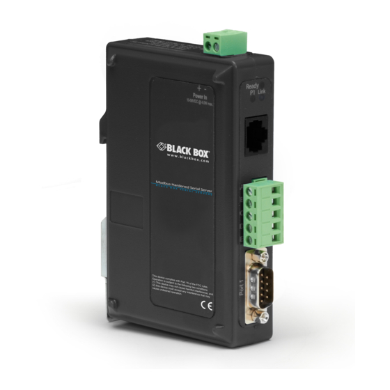
2.4 Hardware Description 1-Port Modbus Hardened Serial Server (LES431A) Figures 2-1 and 2-2 show the front, back, and top panels of the LES431A. Table 2-2 describes its components. Figure 2-1. LES431A front and back panels. Figure 2-2. LES431A top panel. -
Page 11: Modbus Hardened Serial Server Configuration Software
Chapter 2: Overview Table 2-2. LES431A components. Number in Figure 2-1 or 2-2 Component Description (1) RJ-45 connector Connects a standard Ethernet network drop using a straight-through RJ-45 male Ethernet cable. (1) 5-position terminal block connector Connects to an RS-422 or RS-485 serial device when the DB9 M (RS-232) connector is disabled. -
Page 12: Installation And Initial Setup
(mark) state. Signal Ground provides a common mode reference. Connecting the Modbus Hardened Serial Server The LES431A has one serial connection that supports RS-232, RS-422, and RS-485 (2- and 4-wire). The unit has two connectors: a DB9 male connector and a 5-position terminal block. -
Page 13: Connecting Modbus Hardened Serial Servers To A Network
If you select RS-232 mode when you configure the Modbus Hardened Serial Server, you must connect the Modbus serial network to the Modbus Hardened Serial Server via a serial cable. The LES431A is a DTE. If the Modbus network is a DTE, use a null- modem (crossover) cable. -
Page 14: Installing Modbus Hardened Serial Server Software
Chapter 3: Installation and Initial Setup 3.4.1 Installing Modbus Hardened Serial Server Configuration Software Step 1: Download the Modbus Configuration Manager Software from ftp://ftp.blackbox.com. Double-click on the executable file. The file name is Modbus Hardened Serial Server Manager Vx.x.x. a. The following screen will be displayed on your computer. Figure 3-3. - Page 15 Figure 3-5. User information screen. d. Click “Next.” The Destination Folder Screen will be displayed on your computer. The default directory is: C:\Program Files\Black Box\Modbus Hardened Serial Server\ If desired, you can select another location by pressing the “Browse” button.
- Page 16 Chapter 3: Installation and Initial Setup Figure 3-7. Ready to Install Application screen. f. Click “Next.” The software will begin installing. Figure 3-8. Software Installing screen. 724-746-5500 | blackbox.com Page 16...
-
Page 17: Configuring The Modbus Hardened Serial Server Via The Network Connection
To configure via the network, you can use either Modbus Configuration software or the Web interface. Configuring with Modbus Configuration Manager LES431A Modbus Hardened Serial Servers can be configured over the network Modbus Configuration manager software running on a PC. - Page 18 Chapter 3: Installation and Initial Setup To open Modbus Hardened Serial Server Configuration Manager: 1. From the Desktop, click Start—>Programs—>Modbus Hardened Serial Server Manager. An alternate method is to double-click the shortcut installed on the desktop. Figure 3-11. Opening Modbus Hardened Serial Server Configuration Manager. Figure 3-12.
- Page 19 3. If you do not know the IP address, check the “Network” and “I don’t know the IP address of this device” selections and press the “Connect Button.” The software will discover any LES431A Gateways on the network. The configuration manager screen will be displayed on your computer.
- Page 20 Chapter 3: Installation and Initial Setup 5. The default password is no password. Click the “Login” button. The “General” Settings screen will be displayed on your computer. 6. See the Modbus Hardened Serial Server Manager Settings Screen Overview in Figure 3-15. Figure 3-15.
- Page 21 Chapter 3: Installation and Initial Setup 7. See the General Settings screen in Figure 3-16. Figure 3-16. General Settings screen. a. This screen enables you to assign a unique name to the gateway. This allows you to easily identify a particular gateway when multiple devices are used on the same network.
- Page 22 Chapter 3: Installation and Initial Setup Figure 3-17. Changing the password. c. Type your new password in the “Type the new password box.” Verify the password by typing it again in the box provided. To save the new password, click the “Save” button. d.
- Page 23 Chapter 3: Installation and Initial Setup Figure 3-18. Network Setttings screen (DHCP selected). NOTE: To see the rest of the information for Class D listed below that is cut off in Figure 3-18, scroll down in the screen. b. The default network configuration is to receive an IP address assignment from a DHCP server. DHCP controls whether or not a DHCP server is used to set the IP address, subnet mask, and default gateway of the Modbus Hardened Serial Server.
- Page 24 Chapter 3: Installation and Initial Setup Figure 3-19. Network Settings screen (DHCP not selected). d. More information about assigning an IP address without using a DHCP Server is contained in the section “Configuring the Modbus Hardened Serial Server on Networks without a DHCP Server.” e.
- Page 25 Chapter 3: Installation and Initial Setup Figure 3-20. Modbus TCP Settings screen. c. TCP Client Settings: 1. “Connect to Port” identifies the TCP port to be used by the Modbus Hardened Serial Server in TCP client mode. Valid value range is from 1 to 65535. 2.
- Page 26 Chapter 3: Installation and Initial Setup Figure 3-21. TCP Connection Filter “Allow Specific IP addresses to Connect.” b. You can select “and allow a specific range of IP addresses to connect.” This filter is limited to 4 IP address ranges. c.
- Page 27 Chapter 3: Installation and Initial Setup 10. See the PORT x Serial Settings screen in Figure 3-23. a. To access this screen, click the “Next” button or click the Port X Serial link on the left side of the screen. X = The Serial Port number (1 or 2).
- Page 28 Chapter 3: Installation and Initial Setup Figure 3-24. Modbus Port screen. c. “Attached”—This is selectable between Master and Slaves. If “Master” is selected, the Modbus Hardened Serial Server will run in TCP server mode, if “Slaves” is selected, it will run in TCP client mode. d.
- Page 29 Chapter 3: Installation and Initial Setup 12. See the Port x ID Remap screen. a. To access this screen, click the “Next” button or click the “Port x ID Remap” link on the left side of the screen. b. This screen allows you to set Modbus Slave ID Remap settings. Figure 3-25.
- Page 30 Chapter 3: Installation and Initial Setup Figure 3-26. Modbus ID Routing Screen. c. The first box in line is the starting ID of a range you want to route. Valid value range is from 1 to 247. d. The second box in line is the last ID of that range. Valid value range is from 1 to 247. e.
- Page 31 “Function Code”—Valid range is from 1 to 99. g. Save settings by clicking the “Save” button. Configuring with the Web Interface LES431A Modbus Hardened Serial Servers can be configured over the network using a standard Internet browser such as Internet Explorer or Firefox ®...
- Page 32 Chapter 3: Installation and Initial Setup Solve most any Modbus conversion challenge with the Modbus Hardened Serial Server. Modbus Hardened Serial Servers bridge devices on Modbus serial networks (RS-232, RS-422, or RS-485 with those on Modbus TCP networks, allowing seamless integration of any Modbus device. Each serial port is accessible over a LAN or WAN by up to 16 simultaneous Modbus TCP masters.
-
Page 33: Configuring The Modbus Hardened Serial Server On Networks Without A Dhcp Server
Serial Server Manager software. 3.4.3 Configuring the LES431A Modbus Hardened Serial Server on Networks without a DHCP Server Your Modbus Hardened Serial Server comes from the factory set up to receive an IP assignment from a DHCP Server. If there is not a DHCP server on your network, the Modbus Hardened Serial Server will default to IP address 169.254.102.39. - Page 34 115,200 baud, 8 data bits, no parity, and 1 stop bit. c. Enter Console Mode. Press and hold the Modbus Hardened Serial Server’s Mode button for 2 to 10 seconds. The LED indicators will respond as follows: Model: LES431A Port 1 LED: OFF Ready LED: OFF d.
-
Page 35: Configuring The Modbus Hardened Serial Server Via The Serial Port
Re-apply power. Open the Modbus Hardened Serial Server Manager Software and select “Network” as the method to connect to the device. 3.4.4 Configuring the LES431A Modbus Hardened Serial Server via the Serial Port Your Modbus Hardened Serial Server can be configured via a serial port using Modbus Hardened Serial Server Manager. To use this feature, the Modbus Hardened Serial Server's serial port must be connected to the serial port of a PC (using a null-modem cable). - Page 36 Chapter 3: Installation and Initial Setup To configure the Modbus Hardened Serial Server, open the Modbus Hardened Serial Server Manager software and set up the Modbus Hardened Serial Server’s parameters as required. 1. Under Connection, select “Serial Port.” Figure 3-34. Connection. 2.
-
Page 37: Les431A Modbus Hardened Serial Server Operational Connections
The LEDs go back to their normal states when the device resumes normal operation. 3.5 LES431A Modbus Hardened Serial Server Operational Connections LES431A Modbus Hardened Serial Servers can operate in Direct IP Mode. Using LES431A Modbus Hardened Serial Servers in Direct IP Mode A Direct IP connection allows applications using TCP/IP socket programs to communicate with the COM ports on the Modbus Hardened Serial Server. -
Page 38: Upgrading The Modbus Hardened Serial Server Firmware
Chapter 4: Upgrading the Modbus Hardened Serial Server Firmware 4. Upgrading the Modbus Hardened Serial Server Firmware Occasionally, updated firmware may become available for your Modbus Hardened Serial Server. The firmware can be upgraded using the Modbus Hardened Serial Server Manager software. The following procedure describes the firmware updating process: 1. -
Page 39: Uploading The Firmware To The Modbus Hardened Serial Server
Chapter 4: Upgrading the Modbus Hardened Serial Server Firmware To download the latest firmware files from a file: 1. Click the “Browse” button to open an “Open File” dialog box. 2. Browse to the drive and folder containing the firmware file. 3. -
Page 40: Diagnostics
Chapter 5: Diagnostics 5. Diagnostics Clicking the Diagnostics icon opens the “Diagnostics” dialog box and enables you to check the operation of connected Modbus Hardened Serial Servers on the local computer. The Computer Information box displays information about the type of network connections, the IP addresses, Subnet Masks, and Default Gateways in use. - Page 41 Chapter 5: Diagnostics Figure 5-2. Testing a Modbus Hardened Serial Server connection. 724-746-5500 | blackbox.com Page 41...
-
Page 42: Application Examples
Modbus Hardened Serial Servers helps, or if it’s appropriate for their specific needs. The following scenarios are examples only, and many others are possible. Contact Black Box Technical Support at 724-746-5500 or info@blackbox.com for information on other applications. - Page 43 Chapter 6: Application Examples Figure 6-2. Serial Port 1 setup. 3. Configure Serial Port 1. In this case, it is RS-232, 19.2 kbps, 8 data bits, 1 stop bit, and even parity. Save the settings. 4. Access Port 1 Modbus by clicking the link on the left side of the screen. 724-746-5500 | blackbox.com Page 43...
- Page 44 Chapter 6: Application Examples Figure 6-3. Port 1 Modbus. 5. Configure the Port 1 Modbus Settings. In this case, “Attached” should be slaves, “Modbus” should be RTU. The other settings depend on your application. 6. Access Modbus ID Remapping for each port and configure as necessary. 724-746-5500 | blackbox.com Page 44...
- Page 45 Chapter 6: Application Examples Figure 6-4. Port x Modbus Slave ID remapping. 7. Access Modbus ID Routing. Configure as necessary. In this example, Slave ID 200 is mapped to serial port 1. Figure 6-5. Modbus ID routing. 724-746-5500 | blackbox.com Page 45...
- Page 46 Chapter 6: Application Examples 8. Access the Modbus Priority screen and configure as necessary. Figure 6-6. Modbus priority. 724-746-5500 | blackbox.com Page 46...
-
Page 47: Serial And Ethernet Masters, Serial And Ethernet Slaves
Your Modbus Hardened Serial Server can also integrate multiple master devices onto serial and Ethernet Networks. IP slave IP slave ID 151–160 ID 150 IP master Modbus Hardened Serial Server (LES431A) ASCII slave ASCII slave ASCII slave ID 205 ID 1 ID 5 Figure 6-7. Serial and Ethernet masters, Serial and Ethernet slaves. - Page 48 Chapter 6: Application Examples 2. Configure the Modbus slave ID routing. In this case Modbus slaves 1 through 5 and 205 are on Serial Port 1. Modbus slaves 150 and 151 through 160 have IP assignments. Figure 6-9. Modbus Slave ID routing. 724-746-5500 | blackbox.com Page 48...
-
Page 49: Serial Masters, Ip Slaves
9.6 kbps ASCII master Serial Server (LES431A) Figure 6-10. Serial masters, IP slaves. 1. In this example, an ASCII master is connected to Serial Port 1. Configure the serial port as appropriate for this device. Figure 6-11. Port 1 Serial. - Page 50 Chapter 6: Application Examples 2. Access the Modbus screen for each port and configure as appropriate. In this case, Port 1 has an ASCII master attached. Figure 6-12. Port 1 Modbus. 724-746-5500 | blackbox.com Page 50...
-
Page 51: Identical Hard-Coded Slaves
In this example, two slave devices that are hard-coded with the same ID are required. This is accomplished by putting them on different serial ports. Serial RS-485 Modbus Hardened Serial Server (LES431A) ASCII slave ASCII slave ID 1 ASCII Master ID 5 Figure 6-13. -
Page 52: Modbus Help
• A common misperception is that every serial network must terminate with a resistor. While this was true of early serial network configurations, it’s typically the wrong answer—contact Black Box Technical Support at 724-746-5500 or info@blackbox.com and verify if you’re an exception. -
Page 53: Appendix A. Default Modbus Hardened Serial Server Settings
Appendix A: Default Modbus Hardened Serial Server Settings Appendix A. Default Modbus Hardened Serial Server Settings Table A-1. Default server settings. Setting Default Value Server Name User assigned Password Password field is blank from factory DHCP Enabled IP Address DHCP will configure. If a DHCP assignment is not available, the device will default to 169.254.102.39 Net Mask 255.255.255.0... -
Page 54: Appendix B. Connector Pinouts
Appendix B: Connector Pinouts Appendix B. Connector Pinouts B.1 DB9 M Connector Figure B-1. DB9 M connector. Table B-1. DB9 M connector pinout. DB9 M Pin Direction RS-232 Input Input Output Output — Input Output Input Input B.2 Terminal Block Figure B-2. -
Page 55: Standard Ethernet Cable Rj-45 Pinout
Appendix B: Connector Pinouts NOTES: 1. In RS-422 mode, TX lines are outputs and RX lines are inputs. Connect the serial server TXB(+) line to the RXB(+) line of the serial device, and the serial server TXA(-) to the RXA(-) of the serial device. 2. -
Page 56: Appendix C. Glossary
IP—Internet Protocol. IPv4—Internet Protocol version 4. LED—Light emitting diode. Used as a visual indicator. LES431A—Modbus Hardened Serial Server, RS-232/RS-422/485 on serial port. MBAP—MODBUS Application Protocol. MEI—Multi Electrical Interface via RS-232/422/485. Modbus—A request/reply protocol that offers services specified by function codes. - Page 57 NOTES 724-746-5500 | blackbox.com Page 57...
- Page 58 NOTES 724-746-5500 | blackbox.com Page 58...
- Page 59 NOTES 724-746-5500 | blackbox.com Page 59...
- Page 60 About Black Box Black Box provides an extensive range of networking and infrastructure products. You’ll find everything from cabinets and racks and power and surge protection products to media converters and Ethernet switches all supported by free, live 24/7 Tech support available in 30 seconds or less.
Need help?
Do you have a question about the LES431A and is the answer not in the manual?
Questions and answers