Sign In
Upload
Manuals
Brands
Black Box Manuals
Server
Advanced Console Server
Black Box Advanced Console Server Manuals
Manuals and User Guides for Black Box Advanced Console Server. We have
1
Black Box Advanced Console Server manual available for free PDF download: User Manual
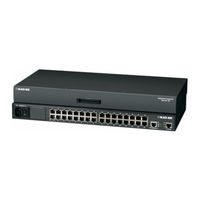
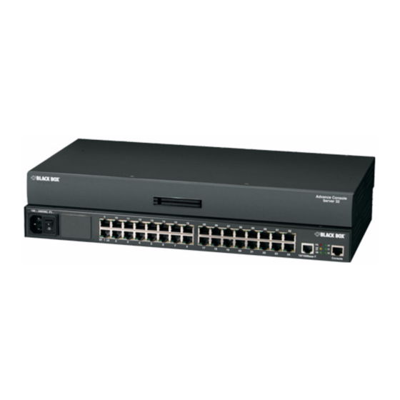
Black Box Advanced Console Server User Manual (392 pages)
Brand:
Black Box
| Category:
Server
| Size: 6.52 MB
Table of Contents
Table of Contents
3
Audience
31
Before You Begin
31
Document Organization
31
Related Documents
33
Table V-1: Typographic Conventions
33
BLACK BOX® Firmware Upgrades
34
Table V-2: Other Terms and Conventions
34
Chapter 1: Introduction
35
Figure 1-2: CS Back with Connectors
36
Figure 1-1: CS Front with PCMCIA Card Slots
36
Overview
36
Product Models and Configurations
36
Table 1-1: Model Numbers and Configuration Options
36
Figure 1-4: CS Connectors
38
Table 1-2: CS Supported Authentication Methods
41
Packet Filtering on CS
43
Structure of IP Filtering
43
Chain
44
Rule
44
Add Rule and Edit Rule Options
45
Vpn
43
Accessing CS and Connected Devices
38
Connectors on the BLACK BOX® CS
38
Prerequisites for Using the Web Manager
39
Web Manager
39
Security
40
Types of Users
40
Authentication
41
Table 1-3: Filter Options for Packet Filtering Rules
45
Table 1-4: TCP Protocol Packet Filtering Options
46
Table 1-5: UDP Protocol Packet Filtering Options
47
Table 1-6: LOG Target Action Options
49
Table 1-7: Tasks for Configuring Access to Connected Devices
53
Figure 1-5: IPDU Integration with CS
54
Configuring Ports for Power Management by Authorized Users
55
Configuring Ports for Power Management Using the CLI
55
Table 1-8: Tasks for Configuring Power Management
55
Options for Managing Power
56
Power Management from the CS Command Line
56
Power Management through the Web Manager
56
Configuring Power Management
54
Snmp
50
Notifications, Alarms, and Data Buffering
51
Syslog Servers
51
Prerequisites for Logging to Syslog Servers
51
Administering Users of Connected Devices
52
Planning Access to Connected Devices
52
Configuring Access to Connected Devices
53
CS and Power Management
53
Table 1-9: Power Management Options in the Web Manager
56
Chapter 2: Installation and Configuration
57
Table 2-1: Shipping Box Contents for LS1004A - LS1048A
58
Figure 2-1: CS Setup Example
58
Table 2-2: Shipping Box Contents for LS1001A
61
Table 2-3: CS Basic Installation Tasks
64
Figure 2-2: Security Advisory Console Message
70
To Use the Wiz Command to Configure Network Parameters
70
Selecting a Security Profile Using the Web Manager
73
To Select a Security Profile
73
Adding Users and Configuring Ports Using the Web Manager
74
Enabling Ports and Assigning Users
74
Other Methods of Accessing the Web Manager
75
To Use a Dynamic IP Address to Access the Web Manager
75
To Use the Default IP Address to Access the Web Manager
75
Figure 2-3: Front Panel PCMCIA Card Slots
76
Installing PCMCIA Cards
76
To Install a PCMCIA Card
76
To Remove a PCMCIA Card
76
Connecting Alterpath PM Ipdus
77
Figure 2-4: PCMCIA Eject Button in Web Manager
77
To Configure a PCMCIA Card
77
Making an Ethernet Connection
65
Mounting the CS
65
To Rack-Mount CS, Perform the Following Steps
65
Connecting Servers and Other Devices to CS
66
To Connect Devices to Serial Ports
66
To Make an Ethernet Connection
66
Making a Direct Connection to Configure the Network Parameters
67
Powering on the CS and the Connected Devices
67
To Connect to the Console Port
67
To Power on the CS
67
Configuring the Network Parameters
68
Performing Basic Network Configuration Using the Wiz Command
68
To Log into CS through the Console
68
To Turn Power on Connected Devices
68
To Change the Root Password
69
Figure 2-5: Alterpath Pms Connected to the CS
78
Table 2-4: Tasks Related to Connecting Alterpath Pms
78
To Daisy-Chain Alterpath Pms to the CS
78
Shipping Box Contents
58
Important Pre-Installation Requirements
62
Java Plug-In Requirement for Serial Port Access
63
To Check Java Plug-In Support in the Browser
63
To Install JRE Version 1.4.2 or Later and Register the Plug-In
63
Basic Installation Procedures
64
Chapter 3: Web Manager for Regular Users
79
Using the Web Manager
79
Figure 3-1: Regular User > Web Manager Login Form
80
Table 3-1: Common Screen Information
81
Connect
82
Logging in to the Web Manager
80
Features of Regular User Forms
81
Figure 3-2: Regular User Form
81
Figure 3-3: Regular User > Connect Form
82
Figure 3-4: Java Applet
83
Table 3-2: Java Applet Buttons
83
Connect to Serial Ports
84
Connection Protocols for Serial Ports
84
Port Access Requirements
84
Table 3-3: Serial Ports Connection Protocols
85
TCP Port Numbers for Serial Ports
85
Figure 3-5: Regular User > IPDU Power Mgmt. Forms
86
To Close an SSH Session
86
To Use SSH to Connect to a Device through a Serial Port
86
Figure 3-7: Regular User > Outlets Manager (with Permissions)
87
Outlets Manager
87
To Close a Telnet Session
85
To Use Telnet to Connect to a Device through a Serial Port
85
IPDU Power Mgmt
86
Connect to CS
83
Figure 3-6: Regular User > Outlets Manager (no Permissions)
87
Table 3-4: Regular User > Outlet Management Buttons
88
Figure 3-8: Regular User > View Ipdus Info
89
Table 3-5: Regular User > Information on the View Ipdus Info Form
89
Figure 3-9: Regular User > IPDU Multi-Outlet (no Permissions)
91
Table 3-6: Regular User > IPDU Multi-Outlet Ctrl. Form Icons
92
Table 3-7: Regular User > Password Management Form
93
To Change Your Password
93
Security
93
View Ipdus Info
89
IPDU Multi-Outlet Ctrl
90
Chapter 4: Web Manager for Administrators
95
BLACK BOX® Web Manager
96
Prerequisites for Using the Web Manager
96
Common Tasks for CS Administrators
97
Table 4-1: Administrator > Common Administrative Tasks
97
Common Features of Administrator Forms
98
Buttons and CS Information
98
Table 4-2: Administrator > Web Manager Buttons
98
Table 4-3: Administrator > Options for Trying, Saving, and Restoring
99
Table 4-4: Administrator > Logout Button and Other Information in the Upper Right
100
To Log into the Web Manager
100
Figure 4-2: Administrator > Web Manager Login Form
101
Figure 4-3: Administrator > Multi Administrator Login Message
102
Figure 4-4: Administrator > Security Advisory Message
103
Expert Mode
104
Figure 4-5: Example of Web Manager Form in Wizard Mode
104
Wizard Mode
104
Overview of Administrative Modes
103
Figure 4-1: Administrator > Web Manager Buttons
98
Logging into the Web Manager
100
Table 4-5: Administrator > CS Configuration and Expert Menus
105
Figure 4-6: Example of Web Manager Form in Expert Mode
105
Chapter 5: Configuring CS in Wizard Mode
107
Step 1: Security Profile
107
Pre-Defined Security Profiles
107
Custom Security Profile
108
Default Security Profile
108
Table 5-1: Wizard > Enabled Services to Access the CS under each
109
Table 5-2: Wizard > Enabled Services to Access the Serial Ports under each Security Profile
109
Table 5-3: Wizard > Enabled Protocols for each Security Profile Shown with a Check Mark
110
Figure 5-1: Administrator > Physical Ports Factory Settings
111
Figure 5-4: Wizard > Step 1: Security Profile Form
113
Figure 5-5: Custom Security Profile Dialog Box
114
Step 2: Network Settings
115
Figure 5-6: Wizard > Step 2: Network Settings - DHCP Disabled
116
Figure 5-7: Wizard > Step 2: Network Settings - DHCP Enabled
117
To Configure the Network Settings
117
Figure 5-8: Wizard > Step 3: Port Profile
118
Step 3: Port Profile
118
Table 5-4: Wizard > Serial Port Profile Parameters and Usage
119
To Set Parameters for All Serial Ports
120
Step 4: Access
121
Figure 5-9: Wizard > Step 4:Access
122
Figure 5-10:Wizard > Step 4: Access Add User Dialog Box
123
Table 5-5: Wizard > Add User Dialog: Field Names and Definitions
123
Figure 5-11: Wizard > Step 4: Change Password Dialog Box
124
To Add a User
124
To Change a Password
125
To Delete a User
125
Figure 5-12:Wizard > Step 5: Data Buffering [Inactive]
126
Step 5: Data Buffering
126
Figure 5-13:Wizard > Step 5: Data Buffering [Local]
127
Figure 5-14:Wizard > Step 5: Data Buffering [Remote]
128
Table 5-6: Wizard > Data Buffering Field Names and Definitions
128
Table 5-7: Wizard > Differences between Remote and Local
129
To Configure Data Buffering
130
Step 6: System Log
131
Figure 5-15:Wizard > Step 6: System Log
132
To Add a Syslog Server
132
Table 5-8: CS Configuration and Expert Menus Chapters
133
To Delete a Syslog Server
133
Figure 5-3: Security Advisory Dialog Box
112
To Select or Configure a Security Profile
112
Figure 5-2: Security and Serial Ports Configuration Alert
111
Serial Port Settings and Security Profiles
111
Chapter 6: Configuring the CS in Expert Mode
135
Overview of Menus and Forms
135
Figure 6-1: Expert Mode Screen Elements
136
Black Box® Cs Installation, Administration, and User's Guide
137
Table 6-1: Expert Mode Menu and Forms
137
Description of Forms in Expert Mode
138
Mapping of the Expert Mode Menus and Forms
137
Table 6-2: Expert > Applications
138
Table 6-3: Expert > Network
139
Table 6-5: Expert > Ports
140
Table 6-4: Expert > Security
140
Table 6-6: Administration
141
Table 7-1: Expert > Applications Menu
145
Applications
146
Connect
146
Chapter 7: Applications Menu & Forms
145
Figure 7-1: Expert > Applications Menu Options
146
Figure 7-2: Expert > Applications > Connect Form
147
Figure 7-3: Expert > SSH Session Java Applet
148
Figure 7-4: Expert > Serial Port Java Applet
149
Figure 7-5: Expert > IPDU Power Mgmt. Tab Options
150
To Connect to a Device through a Serial Port
150
Outlets Manager
151
Figure 7-6: Expert > Applications > IPDU Power Mgmt. > Outlets
152
Table 7-2: Expert > Outlets Manager Icons Description
152
Figure 7-7: Expert > Outlets Manager Icons
153
Figure 7-9: IPDU Power Mgmt. > View Ipdus Info
154
View Ipdus Info
154
Table 7-3: Expert > View Ipdus General Information
155
Table 7-4: Expert > View Ipdus Unit Information
156
To View and Reset IPDU Information
156
Figure 7-10: IPDU Power Mgmt> Users Manager
157
Figure 7-11: Expert > IPDU Power Mgmt. > Users Manager > Add
157
Users Manager
157
To Configure Users to Manage Power Outlets on Ipdus
158
Configuration
159
Figure 7-12: Expert > Applications > IPDU Power Mgmt. > Configuration
160
To Specify Names, Alarms, Syslogging, and over Current Protection for Ipdus
160
Figure 7-13: Expert > Applications > IPDU Power Mgmt. > Software
161
Software Upgrade [For the Alterpath PM]
161
To Download Alterpath PM Software from BLACK BOX
162
To Upgrade Software on an Alterpath PM
162
IPDU Multi-Outlet Ctrl
163
Figure 7-14: Expert > Applications > IPDU Multi-Outlet Ctrl
164
Figure 7-15: Expert > Applications > Multi-Outlet Ctrl [Not Configured]
165
Power Management Icons
165
Prerequisites for Multi-Outlet Control
165
Table 7-5: Expert > IPDU Multi-Outlet Ctrl Form Icons
166
To Power on or Power off a Group of Outlets in Different Power States
167
To Power on or Power off a Group of Outlets in the same Power State
167
To Lock or Unlock a Group of Outlets in Different Lock States
168
To Lock or Unlock a Group of Outlets in the same Power State
168
To Turn the Power of a Group of Outlets off and on Again
168
Figure 7-17:Expert > Applications > IPMI Power Mgmt
169
IPMI Power Management
169
Figure 7-18: Expert > IPMI Power Mgmt. "Add/Edit IPMI Device
170
Table 7-6: Expert > IPMI Information
171
Table 7-7: Expert > IPMI Power Mgmt. Form Icons
171
To Delete, Add, or Edit an IPMI Device to Enable or Disable IPMI Power Management
172
To Configure a Serial Port for IPDU or IPMI Power Management
173
To Manage Power on an IPMI Device
173
Figure 7-20: Expert > Serial Port > Power Management > Enable
174
Figure 7-21: Expert > Power Management Add Outlet Dialog Box
174
Figure 7-22: Expert > Serial Port > Power Management > User
175
To Configure a User for IPDU Power Management While Connected to a Serial Port
175
Figure 7-23: Expert > Serial Port > Power Management > Enable IPMI
176
Terminal Profile Menu
176
To Enable IPMI Power Management of an IPMI Device Connected to the Currently-Selected Port
176
Figure 7-24:Expert > Applications > Terminal Profile Menu
177
Figure 7-26: Expert > Terminal Profile Menu Example
178
To Create a Menu for a Local Computer Terminal
178
Table 8-1: Expert > Network Menu
181
Host Settings
182
Network
182
Figure 7-8: Expert > Edit Outlets Dialog Box
153
To View Status, Lock, Unlock, Rename, or Cycle Power Outlets
153
To Connect to the CS
149
IPDU Power Mgmt
150
Chapter 8: Network Menu & Forms
181
Figure 8-1: Expert > Network > Host Settings [DHCP Enabled]
182
Table 8-2: Expert > Host Settings Form Fields
183
Figure 8-3: Expert > Network > Syslog
187
Figure 8-4: Expert > Network > PCMCIA Management
189
To Configure a PCMCIA Card
190
Configuring a Modem PCMCIA Card
191
PCMCIA Management
188
To Configure Syslogging for Serial Ports and Specify Message Filtering
188
To Configure Host Settings [Expert]
185
Syslog
187
Table 8-3: Expert > Form Fields for a Modem Card
192
Figure 8-5: Expert > PCMCIA Modem Card Configuration Dialog Box
192
Figure 8-14: Expert > PCMCIA CDMA Card Configuration Dialog Box
204
Figure 8-15: Expert > Network > VPN Connections
207
Figure 8-16: Expert > VPN "New/Modify Connection" Dialog Box
208
Table 8-10: Expert > Field and Menu Options for Configuring a VPN
209
To Configure VPN
210
Snmp
211
Figure 8-17: Expert > Network > SNMP
212
Table 8-11: Expert > Fields and Menu Options for SNMP
213
Figure 8-18: Expert > "New/Mod SNMP V1 V2 Configuration
214
Figure 8-19: Expert > "New/Mod SNMP V3 Configuration" Dialog
214
To Configure SNMP
214
Figure 8-20: Expert > Network > Firewall Configuration
216
Firewall Configuration
216
Table 8-12: Expert > Tasks for Configuring SNMP
216
Figure 8-6: Expert > PCMCIA Modem Card Configuration Dialog Box -PPP
193
Figure 8-7: Expert > Modem PCMCIA Card Configuration Dialog Box - Call Back
193
Table 8-4: Expert > Form Fields for an ISDN Card
195
Figure 8-8: Expert > ISDN PCMCIA Card Configuration Dialog Box
195
To Configure an ISDN PCMCIA Card
195
Configuring a GSM PCMCIA Card
196
Figure 8-9: Expert > GSM PCMCIA Card Configuration Dialog
197
Figure 8-11: Expert > Ethernet PCMCIA Card Configuration Dialog
199
Table 8-6: Expert > Form Fields for an Ethernet Card
199
Configuring a PCMCIA Compact Flash Card or a PCMCIA Hard Disk Drive
200
To Configure an Ethernet PCMCIA Card
200
Figure 8-12: Expert > PCMCIA Compact Flash/Hard Disk Configuration Dialog Box
201
Table 8-7: Expert > Form Fields for a Compact Flash/Hard Disk
201
To Configure a Compact Flash PCMCIA Card or a PCMCIA Hard Disk Drive
201
Configuring a Wireless LAN PCMCIA Card
202
Figure 8-13: Expert > PCMCIA Wireless LAN Card Configuration
202
Table 8-8: Expert > Form Fields for a Wireless LAN Card
203
To Configure a Wireless LAN PCMCIA Card
203
Configuring a CDMA PCMCIA Card
204
Table 8-9: Expert > Form Fields for a CDMA Card
204
To Configure a CDMA PCMCIA Card
205
Ejecting a PCMCIA Card
206
To Eject a PCMCIA Card from the Card Slot
206
VPN Connections
206
Figure 8-10: Expert > GSM PCMCIA Card Configuration Dialog Box - Call Back
197
Table 8-5: Expert > Form Fields for a GSM Card
198
To Configure a GSM PCMCIA Card
198
Configuring an Ethernet PCMCIA Card
199
Configuring an ISDN PCMCIA Card
194
To Configure a Modem PCMCIA Card
194
Figure 8-21: Expert > Firewall Configuration "Edit Chain" Dialog
217
Figure 8-22:Firewall Configuration "User-Defined Chain" Message
218
Figure 8-24: Expert > Firewall Configuration "Add Chain" Dialog
219
Figure 8-25: Firewall Configuration "Edit Rules for Chain_Name
219
Figure 8-27: Expert > Firewall Configuration "Add Rule" and "Edit
220
Figure 8-28: Firewall Configuration "Add Rule" and "Edit Rule
221
Figure 8-29:Firewall Configuration "Add Rule" and "Edit Rule" Source and Destination IP and Mask Fields
221
Figure 8-31:Firewall Configuration "Add Rule" and "Edit Rule" Numeric Protocol Fields
222
Figure 8-32:Firewall Configuration "Add Rule" and "Edit Rule" TCP Protocol Fields and Menu Options
223
Table 8-13: Expert > TCP Options Fields
223
Figure 8-33:Firewall Configuration "Add Rule" and "Edit Rule" UDP Protocol Fields
224
Figure 8-34:Firewall Configuration "Add Rule" and "Edit Rule" ICMP Type Menu Options
225
Figure 8-35:Firewall Configuration Input and Output Interface Fields and Fragments Menu Options
226
Table 8-15: Expert > Firewall Configuration Input and Output Interface, and Fragments Fields Definitions
226
Figure 8-36:Firewall Configuration "Add Rule" and "Edit Rule" LOG Target Fields
227
Table 8-16: Expert > Target LOG Options Selection Fields
227
Figure 8-37:Firewall Configuration "Add Rule" and "Edit Rule" REJECT Target Menu Options
228
Table 8-17: Expert > Reject Options Sections
228
Figure 8-38: Expert > Network > Host Tables
232
Static Routes
232
To Define the Cs's IP Address and Hostname
232
Figure 8-39: Expert > Network > Static Routes
233
Figure 8-40: Expert > Static Routes "Add" and "Edit" Dialog Boxes
233
Figure 8-41: Expert > Static Routes "Add" and "Edit" Dialog Boxes
234
Figure 8-42: Expert > Static Routes "Add" and "Edit" Dialog Boxes
235
Table 9-1: Expert > Security Menu
237
Users and Groups
238
Table 8-18: Expert > Fields and Menus for Configuring Static Routes
235
To Configure Static Routes [Expert]
235
Figure 8-23:Firewall Configuration "Delete Default Chain" Message
218
Figure 8-26: Firewall Configuration "Edit Rules for Chain_Name
220
Figure 8-30:Firewall Configuration "Add Rule" and "Edit Rule" Protocol Menu Options
222
Table 8-14: Expert > UDP Options Fields
224
To Add a Chain
229
To Edit a Chain
229
To Add a Rule
230
Host Table
231
To Edit a Rule
231
Chapter 9: Security Menu & Forms
237
Figure 9-1: Expert > Security > Users and Groups Form
238
Adding a User
239
Table 9-2: Expert > Add User Dialog Field Names and Definitions
239
Figure 9-2: Expert > Security > Users and Groups > "Add User" Dialog Box
239
Figure 9-3: Expert > Security > Users and Groups > "Add Group
240
Figure 9-4: Expert > Security > Active Ports Sessions
243
Table 9-3: Expert > Active Ports Sessions Information
243
Authentication
244
To View, Kill, or Refresh Active User Sessions
244
Configuring Authentication for CS Logins
245
Figure 9-5: Expert > Security > Authentication
245
Configuring Authentication Servers for Logins to CS and Connected Devices
246
Figure 9-6: Expert > Security > Authentication > Authtype Form
246
To Configure the CS Login Authentication Method
246
Table 9-4: Tasks for Setting up Authentication Servers
247
Figure 9-7: Expert > Security > Authentication > Radius
248
To Configure a RADIUS Authentication Server
248
Figure 9-8: Expert > Security > Authentication > TACACS
249
To Configure a TACACS+ Authentication Server
249
Group Authorization on TACACS
250
To Configure an LDAP Authentication Server
251
Figure 9-9: Expert > Security > Authentication > LDAP
252
To Configure a Kerberos Authentication Server
253
Figure 9-10: Expert > Administration > Time/Date
254
Figure 9-11: Expert > Security > Authentication > Kerberos
255
To Configure a NIS Authentication Server
255
Figure 9-13: Expert > Security > Security Profile
256
Security Profiles
256
Custom Security Profile
257
Default Security Profile
257
Pre-Defined Security Profiles
257
To Add a User
240
To Add a Group
241
To Change a User's Password
241
To Delete a User or Group
241
Active Ports Sessions
242
To Modify a Group
242
Adding a Group
240
Figure 9-12:Expert > Security > Authentication > NIS
256
Table 9-5: Expert > Enabled Services to Access the CS under each
258
Table 9-6: Expert > Enabled Services to Access the Serial Ports under each Security Profile
258
Table 9-7: Expert > Enabled Protocols for each Security Profile Shown with a Check Mark
259
Figure 9-14: Expert > Physical Ports Default Factory Settings
260
Figure 9-16:Serial Ports Protocol Incompatibility Dialog Box
261
To Select or Configure a Security Profile
261
Figure 9-17: Security Advisory Dialog Box
262
Figure 9-18:Wizard > Step 1: Security Profile Form
263
Figure 9-19: Custom Security Profile Dialog Box
264
Table 9-8: Configuring CS in Expert Mode
265
Security Certificates
266
Certificate for HTTP Security
266
User Configured Digital Certificate
266
X.509 Certificate on SSH
266
Serial Port Settings and Security Profiles
260
Table 10-1: Expert > Ports Menu
267
Chapter 10: Ports Menu & Forms
267
Figure 10-1: Expert > Ports
268
Figure 10-2: Expert > Ports > Physical Ports
269
Figure 10-3: Expert > Ports > Physical Ports > "Modify
270
Figure 10-4: Expert > Ports > Physical Ports > General Form
272
Console Access Server (CAS) Profile Connection Protocols
273
Table 10-2: Expert > Console Connection Protocols
273
Terminal Server (TS) Profile Connection Protocols
273
Table 10-3: Expert > Terminal Server (TS) Connected Protocols
274
Bidirectional Telnet Protocol
275
Modem and Power Management Connection Protocols
276
Table 10-4: Expert > Protocols for Serial Ports Connected to Modems or Ipdus
276
To Configure a Serial Port Connection Protocol for a Console Connection
276
To Select One or more Serial Ports
270
General
271
To Enable or Disable Serial Ports
271
Connection Profiles
272
Figure 10-5: Expert > Ports > Physical Ports > Console Connection
277
Figure 10-8: Expert > Ports > Physical Ports > Bidirectional Telnet
278
To Configure a Serial Port Connection Protocol for a Bidirectional Telnet
278
Physical Ports
269
Figure 10-7:Connection Protocols > Console
278
Figure 10-10: Connection Protocols > Bidirectional Telnet
279
Figure 10-9: Expert > Ports > Physical Ports > Bidirectional Telnet Connection
279
Figure 10-12: Expert > Ports > Physical Ports > Terminal Server
281
Figure 10-13:Connection Protocols > Terminal Server
281
Figure 10-14: Expert > Ports > Physical Ports > Modem Connection
282
To Configure a Serial Port Connection Protocol for an External Modem
282
Figure 10-16: Connection Protocols > Modem
283
Figure 10-17: Expert > Ports > Physical Ports > Power Management
284
To Configure a Power Management Protocol for an IPDU
284
Figure 10-18: Expert > Ports > Physical Ports > Power Management Connection
285
Figure 10-19: Connection Protocols > Power Management
285
Figure 10-20: Access > Authentication Types
286
To Associate an Alias to a Serial Port
287
To Configure Serial Port Settings to Match the Connected Devices
287
Figure 10-21: Expert > Ports > Physical Ports > Serial Port Settings
288
Access
289
Figure 10-22:Expert > Ports > Physical Ports > Access Form
289
Table 10-5: Expert > Access Form Fields
290
Authentication Methods and Fallback Mechanism
291
To Configure User Access to Serial Ports
291
Table 10-6: Expert > Authentication Methods
292
To Configure a Serial Port Login Authentication Method
293
Data Buffering
294
Figure 10-23:Expert > Ports > Physical Ports > Data Buffering
294
Table 10-7: Expert > Procedures to Configure an Authentication
294
Figure 10-24: Expert > Ports > Physical Ports > Data Buffering
295
Table 10-8: Expert > Data Buffering Form Fields
295
To Configure Data Buffering for Serial Ports
297
Multi User
298
Figure 10-25:Expert > Port > Physical Ports >Multi User
299
Table 10-9: Expert > Multi User Form Fields
299
Table 10-10: Expert > Options on the "Allow Multiple Sessions" Menu
300
Figure 10-26:Expert > Ports > Physical Ports > Power Management
301
Power Management
301
Figure 10-27: Expert > Ports > Physical Ports > Power Management
302
Table 10-11: Expert > Power Management Form Fields
302
Figure 10-28: Expert > Ports > Physical Ports > Power Management > Add Outlets Dialog Box
304
To Configure a Serial Port for IPDU or IPMI Power Management
304
Figure 10-29: Expert > Ports > Physical Ports > Power Management>Allow All Users
306
Figure 10-30: Expert > Ports > Physical Ports >Power Management >Allow Users/Groups
306
To Configure a User for IPDU Power Management While Connected to a Serial Port
306
Figure 10-31:Expert > Ports > Physical Ports > Other Form
307
Other
307
Table 10-12: Expert > Ports > Physical Ports > Other Form Fields
308
To Configure TCP Port Number, STTY Options, Break Interval, and the Login Banner for a Serial Port Connected to a Console
309
To Configure Terminal Server Connection Options
310
Virtual Ports
311
Figure 10-32: Expert > Ports > Virtual Ports
312
Figure 10-33: Expert > Ports > Virtual Ports > New/Modify Port
313
Table 10-13: Expert > New/Modify Port Dialog Box Fields
313
Figure 10-34: Expert > Applications > Connect > Serial Pull-Down
315
Figure 10-35: Expert > Ports > Virtual Ports > New/Modify Port
315
To Cluster CS Units or Modify Cluster Configuration
315
To Assign Names to Slave Ports in the Cluster
316
Figure 10-36: Expert > Ports > Virtual Ports > New/Modify > Port Names Dialog Box
317
Ports Status
317
Figure 10-37: Expert > Ports > Ports Status (Read-Only)
318
Ports Statistics
318
To Configure Multiple Sessions and Port Sniffing for One or more Serial Ports
300
Figure 10-11: Expert > Ports > Physical Ports > Terminal Server Active
280
To Configure a Serial Port Connection Protocol for a Terminal Server
280
Table 10-14: Expert > Port Status Read-Only Form
318
Figure 10-38: Expert > Ports > Port Statistics (Read-Only)
319
Table 10-15: Expert > Ports>Port Status Read-Only Form
319
Chapter 11: Administration Menu & Forms
321
Table 11-1: Expert > Administration Menu
321
System Information
322
Figure 11-1: Expert > Administration > System Information
323
Table 11-2: System Information
324
Table 11-3: Expert > Notifications Form Fields
326
Email Notifications Entry
327
To Choose a Method for Sending Notifications for Serial Port Data Buffering Events
327
Notifications
325
To View System Information
325
Figure 11-2: Expert > Administration > Notifications
326
Figure 11-3: Expert > Administration > Notifications > Email > Add
328
Table 11-4: Expert > Email Notifications Dialog Box Fields
328
Figure 11-4: Expert > Administration > Notifications > Pager > Add
330
Pager Notifications Entry
330
Table 11-5: Expert > Pager Notifications Dialog Box
331
To Configure a Trigger for Pager Notification for Serial Ports
331
SNMP Trap Notifications Entry
332
Figure 11-5: Expert > Administration > Notifications > SNMP Trap
333
Table 11-6: Expert > SNMP Trap Notifications Dialog Box
333
Serial Ports Alarm Notification
334
To Configure a Trigger for Serial Port Alarm Notification
334
To Configure a Trigger for SNMP Trap Notification for Serial Ports
334
Figure 11-6: Expert > Administration > Time/Date
335
Time/Date
335
Setting Time and Date with NTP
336
To Configure Time and Date Using an NTP Server
336
To Manually Set the Time and Date
336
Boot Configuration
337
Figure 11-8: Expert > Administration > Boot Configuration
337
Table 11-7: Expert > Boot Configuration Form Fields
338
To Configure CS Boot
339
Backup Configuration
340
Figure 11-9: Expert > Administration > Backup Config
340
Table 11-8: Expert > Backup Config Type FTP Form Fields and
341
Figure 11-10: Expert > Administration > Backup Config > Storage
342
Figure 11-11: Expert > Administration > Upgrade Firmware
344
Table 11-10: Expert > Upgrade Firmware Form Fields
344
To Upgrade the Cs's Firmware
345
Figure 11-12: Expert > Administration > Reboot
346
Reboot
346
To Reboot the CS
346
Figure 11-13:Expert > Administration > Online Help
347
Online Help
347
To Configure the Online Help Path
347
Table 11-9: Expert > Backup Config Type Storage Device Form
342
To Back up or Restore the Configuration Files Using an FTP Server
342
To Back up or Restore the Configuration Files Using a Storage Device
343
Upgrade Firmware
343
To Configure a Trigger for Email Notification for Serial Ports
329
Appendix A: Technical Specifications
349
Formation
351
Safety Guidelines for Rack-Mounting the CS
351
Safety Precautions for Operating the Advanced Console Server
352
Working Inside the Advanced Console Server
354
Replacing the Battery
354
FCC Warning Statement
355
Notice about FCC Compliance for All Advanced Console Server Models
355
Canadian DOC Notice
355
Aviso de Precaución S-Mark Argentina
356
Trabajar dentro del Advanced Console Server
357
Batería
357
Appendix C Supported PCMCIA Cards
359
Table C-1: Supported PCMCIA Cards
359
Glossary
363
Index
381
Advertisement
Advertisement
Related Products
Black Box ServSwitch ACU2028A
Black Box AC159A-R3
Black Box AC650A-4
Black Box AVX-VGA-TP-SRX
Black Box ServSwitch ACX1R-13-SM
Black Box ACS4201A-T
Black Box AC1212A
Black Box ACXC48F-3G
Black Box ACX2MR-DLH-SM
Black Box ACXMODH6FPAC-R2
Black Box Categories
Switch
Media Converter
Extender
Modem
Network Hardware
More Black Box Manuals
Login
Sign In
OR
Sign in with Facebook
Sign in with Google
Upload manual
Upload from disk
Upload from URL