Table of Contents
Advertisement
Black Box Tech Support: FREE! Live. 24/7.
Tech support the
way it should be.
Great tech support is just 30 seconds away at 724-746-5500 or blackbox.com.
About Black Box
Black Box provides an extensive range of networking and infrastructure products. You'll find everything from cabinets and racks and
power and surge protection products to media converters and Ethernet switches all supported by free, live 24/7 Tech support available in
30 seconds or less.
© Copyright 2013. Black Box Corporation. All rights reserved. Black Box
Any third-party trademarks appearing in this manual are acknowledged to be the property of their respective owners.
LES421A user manual, version 2
Document number - 700-0045-01_R001_LES42xA_0913qsg
and the Double Diamond logo are registered trademarks of BB Technologies, Inc.
®
724-746-5500 | blackbox.com
Advertisement
Table of Contents

Related Manuals for Black Box LES421A


Summary of Contents for Black Box LES421A
- Page 1 About Black Box Black Box provides an extensive range of networking and infrastructure products. You’ll find everything from cabinets and racks and power and surge protection products to media converters and Ethernet switches all supported by free, live 24/7 Tech support available in 30 seconds or less.
- Page 2 Order toll-free in the U.S.: Call 877-877-BBOX (outside U.S. call 724-746-5500) Customer FREE technical support 24 hours a day, 7 days a week: Call 724-746-5500 or fax 724-746-0746 Support Information Mailing address: Black Box Corporation, 1000 Park Drive, Lawrence, PA 15055-1018 Web site: www.blackbox.com • E-mail: info@blackbox.com...
- Page 3 Trademarks Used in this Manual Trademarks Used in this Manual Black Box and the Double Diamond logo are registered trademarks of BB Technologies, Inc. Firefox is a registered trademark of Mozilla Foundation. Internet Explorer, Windows, and Windows Vista are registered trademarks of Microsoft Corporation.
- Page 4 FCC and IC RFI Statements Federal Communications Commission and Industry Canada Radio Frequency Interference Statements This equipment generates, uses, and can radiate radio-frequency energy, and if not installed and used properly, that is, in strict accor- dance with the manufacturer’s instructions, may cause inter ference to radio communication. It has been tested and found to comply with the limits for a Class A computing device in accordance with the specifications in Subpart B of Part 15 of FCC rules, which are designed to provide reasonable protection against such interference when the equipment is operated in a commercial environment.
- Page 5 NOM Statement Instrucciones de Seguridad (Normas Oficiales Mexicanas Electrical Safety Statement) 1. Todas las instrucciones de seguridad y operación deberán ser leídas antes de que el aparato eléctrico sea operado. 2. Las instrucciones de seguridad y operación deberán ser guardadas para referencia futura. 3.
-
Page 6: Table Of Contents
Table of Contents Table of Contents 1. Specifications ..........................................7 1.1 General ..........................................7 1.2 Serial Interface ........................................7 1.3 Network..........................................8 1.4 TCP/UDP Ports ........................................9 1.5 Dimensional Diagrams ....................................10 2. Overview ............................................12 2.1 Introduction ........................................12 2.2 Features .......................................... - Page 7 Table of Contents 4.7.3 Setting Up Virtual COM (VCOM) Operation ..........................32 4.7.4 Setting Up Paired Mode Operation ..............................32 4.8 Setting Up Advanced Network Settings ..............................34 4.8.1 Configuring When Network Connections Will Be Forced Closed ..................... 34 4.8.2 Configuring When Data Packets Are Sent ............................35 4.9 Saving/Restoring the Configuration Settings ............................
-
Page 8: Specifications
(1) Reset button Connectors LES421A: (1) DB9 M, (1) 5-pin terminal block, (1) RJ-45, (1) 2-position pluggable terminal block for power; LES422A: (2) DB9 M, (1) RJ-45, (1) 2-position pluggable terminal block for power; LES424A: (4) DB9 M, (1) RJ-45, (1) 3-position pluggable terminal block and (1) locking barrel connector for power Indicators LES421A: (4) LEDs: (1) Ready, (1) Serial, (1) Ethernet Link, (1) Ethernet Speed;... -
Page 9: Network
Chapter 1: Specifications 1.3 Network Network Specifications Character Count 0 to 65535 Client Connection At power-up or upon data arrival Connection Modes Server, Client, VCOM, Paired Delimiters Hex 1 : 01 to FF (begin buffering when hex 1 received); Hex 2: 01 to FF (send serial data if delimiter hex 2 is set and received) Diagnostics DIsplay PC IP, ping, text VCOM, save test config (text readable) Memory... -
Page 10: Tcp/Udp Ports
Chapter 1: Specifications 1.4 TCP/UDP Ports Table 1-1. TCP/UDP ports. Port Description Comments This port is used for configuration of the device using a web browser. This port is always open no matter how you configure the device. If you want to use this method to configure the device from outside of a firewall, then a firewall must 80/tcp Always open for the Web server. -
Page 11: Dimensional Diagrams
Chapter 1: Specifications 1.5 Dimensional Diagrams Figure 1-1. Dimensional diagram of a LES421A or LES422A Hardened Serial Server (dimensions in inches). Page 10 724-746-5500 | blackbox.com... - Page 12 Chapter 1: Specifications Figure 1-2. Dimensional diagram of a LES424A Hardened Serial Server (dimensions in inches and millimeters). 724-746-5500 | blackbox.com Page 11...
-
Page 13: Overview
• LES424A: (2) Ethernet connectors (Ethernet passthrough ports). • Multi-interface serial ports (RS-232, RS-422, RS-485). • LES421A has DB9M and pluggable terminal block serial port connector options. • LES422A and LES424A have DB9M serial port connectors. • All serial ports are software selectable for RS-232, RS-422, or RS-485 2- and 4-wire communication. -
Page 14: What's Included
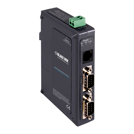
Black Box Web site (www.blackbox.com) and enter LES421A, LES422A, or LES424A in the search bar. 2.4 Hardware Description 2.4.1 1-Port Hardened Serial Server (LES421A) Figures 2-1 and 2-2 show the front and top panels of the LES421A. Table 2-2 describes its components. Figures 2-1 and 2-2. LES421A front and top panels. 724-746-5500 | blackbox.com... -
Page 15: 2-Port Hardened Serial Server
Chapter 2: Overview Table 2-2. LES421A components. Number in Figure 2-1 or 2-2 Component Description (1) RJ-45 connector Connects a standard Ethernet network drop using a straight-through RJ-45 male Ethernet cable. (1) 5-position terminal block connector Connects to an RS-422 or RS-485 serial device when the DB9 M (RS-232) connector is disabled. -
Page 16: 4-Port Hardened Serial Server
Chapter 2: Overview Table 2-3. LES422A components. Number in Figure 2-3 or 2-4 Component Description (1) RJ-45 connector Connects a standard Ethernet network drop using a straight-through RJ-45 male Ethernet cable. (2) DB9 male connectors Connects to RS-232, RS-422, or RS-485 serial devices. (1) 2-wire terminal block connector Removable 2-position terminal block with +, -, and chassis ground connections. -
Page 17: Configuration Software
Chapter 2: Overview Figure 2-6. LES424A back panel. Table 2-4. LES424A components. Number in Figure 2-5 or 2-6 Component Description (1) Power LED Lights when power to the unit is on. Lights green continuously when the unit is initializing. (1) Ready LED Flashes once per second when the system is operating correctly. -
Page 18: Installation And Initial Setup
8 data bits, no parity, 1 stop bit), and no flow control. NOTE: The LES421A, LES422A, and LES424A are configured as DTEs. If they are connected to a computer or other DTE device, use a null-modem (crossover) cable. If the serial device is configured as a DCE, use a straight-through cable. -
Page 19: Rs-422
Chapter 3: Installation and Setup 3.2.2 RS-422 RS-422 connections support two signal pairs: TDA (-), TDB (+), RDA (-), RDB (+), and GND. The data lines are differential pairs (A and B) in which the B line is positive relative to the A line in the idle (mark) state. In RS-422, the transmitter is always enabled. Signal Ground provides a common mode reference for the signal lines. -
Page 20: Hardened Serial Server Configuration
Chapter 3: Installation and Initial Setup 3.5 Hardened Serial Server Configuration The Hardened Serial Servers can be configured using three methods: • Via the network using Hardened Serial Server Software. • Via the network using a Web browser. • Via a serial port using Hardened Serial Server Software (Console Mode). 3.5.1 Configuring via the Network using Hardened Serial Server Software Hardened Serial Servers can be configured over the network using Hardened Serial Server Software running on a networked PC. -
Page 21: Configuring Via A Serial Port Using Hardened Serial Server Software (Console Mode)
Chapter 3: Installation and Initial Setup 3.5.3 Configuring via a Serial Port using Hardened Serial Server Software (Console Mode) Your Hardened Serial Server can be configured via any serial port, using Hardened Serial Server Software. To use this feature, a serial port on the serial server must be connected to the serial port of a PC (using a null modem cable). -
Page 22: Installing And Starting Hardened Serial Server Software
Chapter 3: Installation and Initial Setup physically located on the host PC. When a virtual COM port is configured on the PC (using Serial Server Software), a new COM port appears in the Device Manager. Windows programs are able to interface to the virtual COM port using standard Windows API calls. When a program on the PC opens the new COM port, it communicates directly with the remote serial device connected to the serial server. -
Page 23: Discovering Hardened Serial Servers
Chapter 3: Installation and Initial Setup If you are configuring the Hardened Serial Server via the network, select “Network”; if you are configuring it via the serial port, select “Serial Port.” If you already know the IP address of the Hardened Serial Server, click “The device is at this IP address”; if not, leave “I don’t know the IP address of the device”... -
Page 24: Configuring The Hardened Serial Server
Figure 4-1. Hardened Serial Server Software Configuration window. NOTE: The screen shots shown in this manual refer to the LES421A. Your screen will display the model name/number and serial num- ber of your device (LES421A, LES422A, or LES424A). All menus, functions and options shown on the screen shots in this manu- al apply to your LES421A, LES422A, or LES424A device. -
Page 25: Hardened Serial Server Information Table
The Hardened Serial Server information table contains information about all Hardened Serial Servers that have been discovered on the network or serial ports. Table 4-1. Serial server information table. Server Name Connection Port 1 Port 2 Port 3 Port 4 LES421A 169.254.0.41 TCP:S:4000=COM5, in use — — — LES422A 169.254.0.42 TCP: 5000 = COM6 TCP: 5001 = COM7 —... -
Page 26: Logging In
Chapter 4: Configuring the Hardened Serial Server It includes the following: • Masthead with the name and IP address of the currently selected Hardened Serial Server. • Contents sidebar (on the left side) containing hyperlinks to the following configuration pages: - General - Network - Port x Serial (x = port number;... -
Page 27: Navigating The Configuration
Chapter 4: Configuring the Hardened Serial Server 4.3 Navigating the Configuration Pages There are two ways to move from page to page in the Hardened Serial Server Software: by clicking a specific link, or by clicking “Next” or “Back” to move through the pages sequentially. NOTE: Always remember to click “Save”... -
Page 28: Setting Up Ip Addressing
Chapter 4: Configuring the Hardened Serial Server 4.5 Setting Up IP Addressing On the Network Configuration page, you can configure the Hardened Serial Server to use dynamic (DHCP) or static IP addressing on the network. Figure 4-7. Network Configuration page. 4.5.1 Setting Up Dynamic IP Addressing 1. -
Page 29: Setting Up Serial Ports
Chapter 4: Configuring the Hardened Serial Server 4.6 Setting Up Serial Ports On the Serial Port Configuration page, you can configure the communications parameters of the current serial port. Parameters include the port mode, baud rate, data bits, parity, stop bits, and type of flow control. Figure 4-9. - Page 30 You must set up the TCP port number that the Hardened Serial Server will listen for incoming connections and set the maximum number of simultaneous connections it will support (one for the LES421A, up to two for the LES422A, and up to four for the LES424A).
-
Page 31: Udp Configuration
Chapter 4: Configuring the Hardened Serial Server Figure 4-11. TCP server settings. 4.7.2 UDP Configuration UDP (User Datagram Protocol) enables applications using UDP socket programs to communicate with the serial ports on the Hardened Serial Server. UDP protocol provides connectionless communications, which allows data to be broadcast to and received from multiple nodes on a network. - Page 32 Chapter 4: Configuring the Hardened Serial Server Setting the Hardened Serial Server to use UDP 1. Select UDP protocol. Options are provided for sending and receiving data to and from: • Nobody (one-way communication only). • Everyone on a specific UDP port. •...
-
Page 33: Setting Up Virtual Com (Vcom) Operation
Chapter 4: Configuring the Hardened Serial Server 4.7.3 Setting Up Virtual COM (VCOM) Operation When the Network Protocol is set to VCOM (Virtual COM Port), the Hardened Serial Server communicates over the network with a PC, acting as a remote COM port for the computer. Figure 4-13. - Page 34 Chapter 4: Configuring the Hardened Serial Server 1. Select “Paired” protocol. 2. Select “to initiate connections (client).” 3. Type the IP address and TCP port numbers of the server in the appropriate text boxes. 4. Select: • “at power up”—if you want the Hardened Serial Server to always be connected. •...
-
Page 35: Setting Up Advanced Network Settings
Chapter 4: Configuring the Serial Server Figure 4-17. IP address ranges. 4.8 Setting Up Advanced Network Settings On the “Advanced Network Settings” window, you can configure if network connections are automatically closed due to inactivity and when serial data is forwarded to the network. Data that is received by the serial port is normally buffered for a short period of time and then forwarded over the Ethernet to the remote device. -
Page 36: Configuring When Data Packets Are Sent
Chapter 4: Configuring the Hardened Serial Server Figure 4-19. Advanced configuration—forcing connections closed. To close a network connection if no data is received from the network for a period of time: 1. Select the “I want to close a connection when data is not received on that connection for a period of time” checkbox. 2. - Page 37 Chapter 4: Configuring the Hardened Serial Server Figure 4-20. Advanced Configuration—Configuring when data packets are sent. Page 36 724-746-5500 | blackbox.com...
-
Page 38: Saving/Restoring The Configuration Settings
Chapter 4: Configuring the Hardened Serial Server To wait until a specific amount of data is received on the serial port before sending it across the network: 1. Select “I want to wait for a specific amount of data to be received by the serial port before sending it” in the “Character Count” box. 2. -
Page 39: Adding Virtual Com Ports
Chapter 4: Configuring the Hardened Serial Server Figure 4-21. Save Configuration page. To save the configuration to the Hardened Serial Server, and re-boot it so that the configuration settings will take effect: 1. Click “Save.” 4.10 Adding Virtual COM Ports Clicking the “Add”... -
Page 40: Removing Virtual Com Ports
Chapter 4: Configuring the Hardened Serial Server When the process of adding the virtual COM port is complete (indicated by the progress bar), the “Serial port is successfully installed” dialog box appears. 6. Click “OK.” 4.11 Removing Virtual COM Ports Clicking the “Remove”... -
Page 41: Upgrading The Hardened Serial Server Firmware
Chapter 5: Upgrading the Hardened Serial Server Firmware 5. Upgrading the Hardened Serial Server Firmware Occasionally, updated firmware may become available for your Hardened Serial Server. The firmware can be upgraded using the Hardened Serial Server Software. The following procedure describes the firmware updating process: 1. -
Page 42: Uploading The Firmware To The Hardened Serial Server
Chapter 5: Upgrading the Hardened Serial Server Firmware 5.2 Uploading the Firmware to the Hardened Serial Server 1. In the “Hardened Serial Server Selection” drop-down list, select the Hardened Serial Server to be upgraded. 2. In the ”Firmware Description” drop-down list, select the firmware to upload to the Hardened Serial Server. 3. -
Page 43: Operation
Hardened Serial Servers have LED indicators for Power, Serial Server Ready, Ethernet Speed and Link status, and Serial Port status. Figures 6-1 through 6-3 show the location of the LEDs on the LES421A, LES422A, and LES424A servers. Figure 6-1. Front and top panels of the LES421A. - Page 44 Chapter 6: Operation Figure 6-2. Front panel of the LES422A. Table 6-2. LEDs and switches on the LES422A serial server. Number in Figure 6-2 LED Indicator Description Each serial port has an associated LED. The Serial Port LED flashes (green) when data is being (2) Serial Port LEDs (P1, P2) transmitted or received on the serial ports.
- Page 45 Chapter 6: Operation 4 3 4 5 Figure 6-3. Front panel of the LES424A. Table 6-3. LEDs on the LES424A serial server. Number in Figure 6-3 LED Indicator Description (1) Power LED The Power LED illuminates when 10 to 58 VDC power is applied to either power connector. The Ready LED (green) illuminates continuously while the unit is initializing.
-
Page 46: Reset Switch
Chapter 6: Operation 6.2 Reset Switch Figure 6-4 shows the location of the Reset switch on the LES421A, LES422A, and LES424A Hardened Serial Servers. Reset Switch Reset Switch Figure 6-4. Left: top view of the LES421A or LES422A; Right: back view of the LES424A. -
Page 47: Diagnostics
Chapter 7: Diagnostics 7. Diagnostics Clicking the “Diagnostics” icon opens the Diagnostics dialog box and enables you to check the operation of connected serial servers and VCOM ports on the local computer. The Computer Information box displays information about the type of network connections, the IP addresses, Subnet Masks, and Default Gateways in use. -
Page 48: Testing A Virtual Com Port
Chapter 7: Diagnostics Figure 7-2. Testing a Hardened Serial Server Connection. 7.2 Testing a Virtual COM Port 1. Click the “Diagnostics” icon. The “Diagnostics” dialog box appears. 2. Select the option: “a virtual communications port” 3. In the drop-down box, select the specific COM port you want to check. 4. -
Page 49: Listing/Descriptions Of Hardened Serial Server Settings
Chapter 8: Listing/Descriptions of Hardened Serial Server Settings 8. Listing/Descriptions of Hardened Serial Server Settings The following Hardened Serial Server properties are ordered alphabetically to assist you in finding the information you need. Baud Rate is the communication speed of the link between the Hardened Serial Server and the device attached to its serial port. Both devices must be configured to operate at the same baud rate. - Page 50 Chapter 8: Listing/Descriptions of Hardened Serial Server Settings Dynamic Host Configuration Protocol (DHCP) is a protocol used on special servers that supply IP addresses to network nodes on request. When DHCP is enabled on the Hardened Serial Server, on power up it sends a DHCP request to the DHCP server, which assigns a dynamic IP address, subnet mask, and default gateway to the Hardened Serial Server.
- Page 51 Chapter 8: Listing/Descriptions of Hardened Serial Server Settings Figure 8-1. Network IP properties. b. Click “Internet Protocol (TCP/IP)” and then click “Properties.” Change the parameters to the following: • IP Address = 169.254.102.1 • Subnet Mask = 255.255.255.0 • Default Gateway = 169.254.102.100 Figure 8-2.
- Page 52 Chapter 8: Listing/Descriptions of Hardened Serial Server Settings c. Use the Hardened Serial Server Software to search for, discover, and configure the unit. 2. Method Two: Change the Hardened Serial Server’s network setting to match your PC using Console mode. a.
- Page 53 Password. When you first receive the LES421A, LES422A, or LES424A Hardened Serial Server from the factory, the password is blank so that you can initially access the Hardened Serial Server without entering a value into this field. To ensure security, you should create and save a password the first time you configure the serial server.
- Page 54 • For a Class D network (IP addresses 224.0.0.0 through 239.255.255.255) and Class E Networks (IP addresses 240.0.0.0 through 255.255.255.255), the subnet mask is ignored. • LES421A, LES422A, and LES424A servers come from the factory with a default subnet mask value of: 255.255.255.0. Transmission Control Protocol (TCP) provides reliable connection-oriented network communication with error checking. In TCP mode the Hardened Serial Server can be configured as a client or a server.
-
Page 55: Appendix A. Default Server Settings
Appendix A: Default Server Settings Appendix A. Default Server Settings Table A-1. Default server settings. Setting Default Value Server Name LES421A, LES422A, or LES424A Serial Number Printed on side of unit. Password Password field is blank from factory. DHCP Enable... -
Page 56: Appendix B. Connector Pinouts
Appendix B: Connector Pinouts Appendix B. Connector Pinouts B.1 DB9 M Connector Figure B-1. DB9 M connector. Table B-1. DB9 M connector pinout. DB9 M Pin RS-232 Direction (RS-232) RS-422/485 4-Wire RS-485 2-Wire Input RDA (-) — Input RDB (+) —... -
Page 57: Standard Ethernet Cable Rj-45 Pinout
Appendix B: Connector Pinouts NOTES: 1. In the RS-422 mode, TX lines are outputs and RX lines are inputs. Connect the Hardened Serial Server TXB(+) line to the RXB(+) line of the serial device, and the Hardened Serial Server TXA(-) to the RXA(-) of the serial device. 2. - Page 58 NOTES 724-746-5500 | blackbox.com Page 57...
- Page 59 NOTES Page 58 724-746-5500 | blackbox.com...
- Page 60 NOTES 724-746-5500 | blackbox.com Page 59...
Need help?
Do you have a question about the LES421A and is the answer not in the manual?
Questions and answers