Table of Contents
Advertisement
Quick Links
Download this manual
See also:
Manual
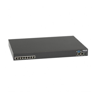
Value-Line and Advanced Console Servers User's Manual
Securely manage data center and network
equipment from anywhere in the world.
Order toll-free in the U.S.: Call 877-877-BBOX (outside U.S. call 724-746-5500)
Customer
FREE technical support 24 hours a day, 7 days a week: Call 724-746-5500 or fax 724-746-0746
Support
Mailing address: Black Box Corporation, 1000 Park Drive, Lawrence, PA 15055-1018
Information
Web site: www.blackbox.com • E-mail: info@blackbox.com
LES1108A
LES1208A-R2
LES1116A
LES1216A-R2
LES1132A
LES1232A
LES1148A
LES1248A-R2
LES1308A
LES1408A
LES1316A
LES1416A
LES1332A
LES1432A
LES1348A
LES1448A
BLACK BOX
LES1508A
®
Advertisement
Table of Contents

Related Manuals for Black Box LES1108A


Summary of Contents for Black Box LES1108A
- Page 1 Order toll-free in the U.S.: Call 877-877-BBOX (outside U.S. call 724-746-5500) Customer FREE technical support 24 hours a day, 7 days a week: Call 724-746-5500 or fax 724-746-0746 Support Mailing address: Black Box Corporation, 1000 Park Drive, Lawrence, PA 15055-1018 Information Web site: www.blackbox.com • E-mail: info@blackbox.com...
- Page 2 Value-Line and Advanced Console Servers Manual Trademarks Used in this Manual Black Box and the Double Diamond logo are registered trademarks of BB Technologies, Inc. Cisco is a registered trademark of Cisco Technology, Inc. Mac is a registered trademark of Apple Computers, Inc.
- Page 3 We‘re here to help! If you have any questions about your application or our products, contact Black Box Tech Support at 724-746-5500 or go to blackbox.com and click on “Talk to Black Box.” You’ll be live with one of our technical experts in less than 60 seconds.
- Page 4 Value-Line and Advanced Console Servers Manual Federal Communications Commission and Industry Canada Radio Frequency Interference Statements This equipment generates, uses, and can radiate radio-frequency energy, and if not installed and used properly, that is, in strict accordance with the manufacturer’s instructions, may cause inter ference to radio communication. It has been tested and found to comply with the limits for a Class A computing device in accordance with the specifications in Subpart B of Part 15 of FCC rules, which are designed to provide reasonable protection against such interference when the equipment is operated in a commercial environment.
- Page 5 Value-Line and Advanced Console Servers Manual Instrucciones de Seguridad (Normas Oficiales Mexicanas Electrical Safety Statement) 1. Todas las instrucciones de seguridad y operación deberán ser leídas antes de que el aparato eléctrico sea operado. 2. Las instrucciones de seguridad y operación deberán ser guardadas para referencia futura. 3.
- Page 6 2.2.2 LES1116A, L ES1132A a nd L ES1148A p ower 2.2.4 LES1108A p ower 2.3 Network c onnection 23 2.4 Serial P ort c onnection ...
- Page 7 4.1.8 NMEA Streaming 4.1.9 Cisco USB console connection 4.2 Add/ E dit U sers 57 4.3 Authentication 60 4.4 Network H osts 60 4.5 Trusted ...
- Page 8 6.2 SDT C onnector c lient c onfiguration 104 6.2.1 SDT C onnector i nstallation 6.2.2 Configuring a n ew c onsole s erver g ateway i n t he S DT C onnector c lient ...
- Page 9 POWER & E NVIRONMENTAL M ANAGEMENT 151 8.1 Remote P ower C ontrol ( RPC) 151 8.1.1 RPC c onnection 8.1.2 RPC a ccess p rivileges a nd a lerts ...
- Page 10 11.2 Upgrade F irmware 199 11.3 Configure D ate a nd T ime 199 11.4 Configuration B ackup 200 11.5 Delayed C onfiguration C ommit 202 ...
-
Page 11: Portmanager C Ommands
15.1.7 Running c ustom s cripts w hen a c onfigurator i s i nvoked 15.1.8 Backing-‐up t he c onfiguration a nd r estoring u sing a l ocal U SB s tick ... -
Page 12: Hardware Specification
APPENDIX A. CLI C ommands a nd S ource C ode B. Hardware S pecification C. Safety a nd C ertifications D. Connectivity a nd S erial I /O E. -
Page 13: This Manual
This U ser’s M anual w alks y ou t hrough i nstalling a nd c onfiguring y our B lack B ox C onsole S erver (LES1108A, L ES1116A, L ES1132A, L ES1148A, L ES1508A) o r A dvanced C onsole S erver ( LES1208A-‐R2, ... -
Page 14: Management Console
11. S ystem M anagement Covers a ccess t o a nd c onfiguration o f s ervices t hat w ill r un o n t he console ... -
Page 15: Manual Conventions
A User can also use the Management Console, but has limited menu access to control select devices, review t heir l ogs a nd a ccess t hem u sing t he b uilt-‐in j ava t erminal o r c ontrol p ower t o t hem. The console server runs an embedded Linux operating system, and experienced Linux® and UNIX® users ... - Page 16 October 2 011 2.0 Release f or V 2.8 f irmware a nd l ater December 2 012 3.0 ...
- Page 17 Copyright ©Black B ox C orporation 2 014. A ll R ights R eserved. Information i n t his d ocument i s s ubject t o c hange w ithout n otice a nd d oes n ot r epresent a c ommitment on ...
-
Page 18: Installation
LES1116A 16 -‐ 1 1 -‐ 00 Single A C 16/64MB LES1108A 8 -‐ 1 1 -‐ 00 Ext A C/DC 8/16MB ... - Page 19 If y ou a re i nstalling t he c onsole s erver i n a r ack, y ou w ill n eed t o a ttach t he r ack m ounting brackets ...
- Page 20 DB9F-‐RJ45S s traight a nd D B9F-‐RJ45S c ross-‐over c onnectors USB micro-AB adapter cable Antenna with 10 foot extension cable Dual I EC A C p ower c ords ...
-
Page 21: Power Connection
Printed Q uick S tart G uide 2.1.5 Kit c omponents L ES1108A C onsole S erver LES1108A C onsole S erver ... - Page 22 VDC connector from the power supply plugs into the 12VDC (PWR) power socket on the side of the LES1508A. 2.2.2 LES1408A -‐ L ES1448A, L ES1308A-‐ L ES1348A a nd L ES1208A -‐ L ES1248A p ower The ...
-
Page 23: Network Connection
The RJ-‐45 serial ports are located on the rear panel of the LES1108A and on the front panel of the ... - Page 24 PIN SIGNAL DEFINITION DIRECTION 1 RTS Request T o S end Output 2 DSR Data S et R eady Input 3 DCD Data ...
-
Page 25: Usb Memory Stick
connecting to USB consoles of Managed Devices (e.g. for managing UPS supplies) attaching other external USB peripherals (e.g. an external USB memory stick or modem) adding supported Sierra Wireless cellular USB modems plugging in USB hubs to provide additional ports The USB1.1 port is best reserved for use with an external USB memory stick... -
Page 26: Initial System Configuration
Chapter 3 Initial System Configuration SYSTEM C ONFIGURATION Introduction This c hapter p rovides s tep-‐by-‐step i nstructions f or t he c onsole s erver’s i nitial c onfiguration, a nd f or connecting ... -
Page 27: Subnet Mask
Subnet m ask: 2 55.255.255.0 If y ou w ant t o r etain y our e xisting I P s ettings f or t his n etwork c onnection, c lick A dvanced ... - Page 28 You w ill b e p rompted t o l og i n. E nter t he d efault administration u sername a nd a dministration password: ...
-
Page 29: Administrator Password
After completing each of the above steps, you can return to the configuration list by clicking in the top left c orner o f t he s creen o n t he B lack B ox l ogo. ... - Page 30 Click A pply. S ince y ou h ave c hanged t he p assword y ou w ill b e p rompted t o l og i n a gain. T his time, ...
-
Page 31: Network I P A Ddress
3.3 Network I P a ddress The n ext s tep i s t o e nter a n I P a ddress f or t he p rincipal E thernet ( LAN/Network/Network1) p ort o n t he console ... - Page 32 Enter h ttp://new I P a ddress t o r econnect t he b rowser o n t he P C/workstation t hat i s c onnected to ...
- Page 33 Specify t he M aximum a ttempts p er u pdate i .e. t he n umber o f t imes t o a ttempt a n u pdate ...
- Page 34 The Services Access settings specify which services the Administrator can use over which network interface to access the console server. It also nominates the enabled services that the Administrator and the User can use to connect through the console server to attached serial and network connected devices.
- Page 35 in rackmount models. To modify the default SNMP settings, the Administrator must make the edits at the command line as described in Chapter 15—Advanced Configuration. TFTP This service will set up the default tftp server on the USB flash card (and is relevant ...
-
Page 36: Communications S Oftware
To e nable a s ervice c heck E nable. F or s ome s ervces y ou w ill b e a sked t o s pecify t he T CP/IP p ort to ... - Page 37 Black B ox p rovides t he S DT C onnector J ava a pplet a s t he r ecommended c lient s oftware t ool. Y ou c an u se other ...
-
Page 38: Management N Etwork C Onfiguration
To u se P uTTY f or a n S SH t erminal s ession f rom a Windows client, enter the console server’s IP address ... - Page 39 3.6.1 Enable t he M anagement L AN The LES1508A, LES1408A, LES1416A, LES1432A, LES1448A, LES1308A, LES1316A, LES1332A, LES1348A, LES1208A-‐R2, LES1216A-‐R2, LES1232A and LES1248A-‐R2 console servers provide a firewall, router, and DHCP ...
- Page 40 Note You can configure the second Ethernet port as either a gateway port or as an OOB/Failover port (but not both). Make sure you did not allocate Network 2 as the Failover Interface when you configured the principal Network connection on the System: IP menu. The ...
- Page 41 Enter t he D efault L ease t ime a nd M aximum L ease t ime i n s econds. T he l ease t ime i s t he t ime that ...
- Page 42 By d efault, t he f ailover i s n ot e nabled. T o e nable, s elect t he N etwork p age o n t he S ystem: I P menu. ...
- Page 43 Click A pply. Y ou h ave s elected t he f ailover m ethod. I t i s n ot a ctive u ntil y ou s pecify t he e xternal sites ...
- Page 44 Select E nable B ridging o n t he S ystem: I P G eneral S ettings m enu. Select B ridge I nterfaces o r B ond I nterfaces When ...
- Page 45 To add to the static route to the route table of the system: Select the Route Settings tab on the System: IP General Settings menu. Enter a meaningful Route Name for the route . In the Destination Network/Host field enter the IP address of the destination network/host that the route provides access to.
-
Page 46: Serial Port, Host, Device & User Configuration
Chapter 4 Serial Port, Host, Device & User Configuration SERIAL PORT AND NETWORK HOST Introduction The Black Box console server enables access and control of serially attached devices and network attached devices (hosts). The Administrator must configure access privileges for each of these devices, ... - Page 47 Console Server Mode is the default and this enables general access to serial console port on the serially a ttached d evices. Device Mode sets the serial port up to communicate with an intelligent serial controlled PDU, UPS, ...
- Page 48 Specify a l abel f or t he p ort. Select the appropriate Baud Rate, Parity, Data Bits, Stop Bits, and Flow Control for each port. (Note: T he R S-‐485/RS-‐422 o ption i s n ot r elevant f or c onsole s ervers.) Before proceeding with further serial port configuration, connect the ports to the serial devices ...
- Page 49 Logging L evel This s pecifies t he l evel o f i nformation t o b e l ogged a nd m onitored ( referto C hapter 7 — Alerts ...
- Page 50 If the remote communications are tunneled with SDT Connector, then you can use Telnet to securely a ccess t hese a ttached d evices ( refer t o t he N ote b elow). ...
- Page 51 PuTTY can be downloaded at http://www.tucows.com/preview/195286.html SSH We recommend that you use SSH as the protocol where the User or Administrator connects to t he c onsole s erver ( or c onnects t hrough t he c onsole s erver t o t he a ttached s erial c onsoles) over ...
- Page 52 For a U ser n amed “ fred” t o a ccess s erial p ort 2 , w hen s etting u p t he S SHTerm o r t he P uTTY SSH ...
- Page 53 Web T erminal S electing W eb T erminal e nables w eb b rowser a ccess t o t he s erial p ort v ia M anage: Devices: ...
- Page 54 For c onfiguration d etails, r efer t o C hapter 6 .6—Using S DT C onnector t o T elnet o r S SH c onnect t o d evices that ...
- Page 55 4.1.6 Serial B ridging M ode With serial bridging, the serial data on a nominated serial port on one console server is encapsulated into ...
-
Page 56: Nmea Streaming
For e xample, i f t he c omputer a ttached t o s erial p ort 3 s hould n ever s end a nything o ut o n i ts s erial console ... - Page 57 4.2 Add/ E dit U sers The Administrator uses this menu selection to set up, edit, and delete users, and to define the access ...
- Page 58 2. Membership of the user group provides the user with limited access to the console server and connected Hosts and serial devices. These Users can access only the Management section of the Management Console menu and they have no command line access to the console server.
- Page 59 Click A dd U ser t o a dd a n ew u ser. Add a U sername a nd a c onfirmed P assword f or e ach n ew u ser. Y ou m ay a lso i nclude information ...
- Page 60 Click A pply. T he n ew u ser c an n ow a ccess t he N etwork D evices, P orts, a nd R PC O utlets y ou nominated ...
-
Page 61: Trusted N Etworks
Selecting S erial & N etwork: N etwork H osts p resents a ll t he n etwork c onnected H osts t hat h ave been ... - Page 62 Select S erial & N etwork: T rusted N etworks. To a dd a n ew t rusted n etwork, s elect A dd R ule. ...
- Page 63 Note The above Trusted Networks will limit Users and Administrators access to the console serial ports. They do not restrict access to the console server itself or to attached hosts. To change the default settings for this access, you will to need to edit the IPtables rules as described in Chapter 14—Advanced.
- Page 64 Next, y ou m ust s elect w hether t o g enerate k eys u sing R SA a nd/or D SA ( if u nsure, s elect o nly R SA). Generating ...
- Page 65 Next, y ou m ust r egister t he P ublic K ey a s a n A uthorized K ey o n t he S lave. I n a c ase t hat h as o nly o ne Master ...
- Page 66 Once t he S SH c onnection h as b een e stablished, t he s ystem a sks y ou t o a ccept t he k ey. A nswer y es a nd the ...
- Page 67 Once y ou h ave a dded a ll t he S lave c onsole s ervers, y ou c an a ssign a nd a ccess t he S lave s erial p orts a nd the ...
-
Page 68: Managed D Evices
This serial port redirector software is loaded in your desktop PC, and it allows you to use a serial device that’s c onnected t o t he r emote c onsole s erver a s i f i t w ere c onnected t o y our l ocal s erial p ort. ... - Page 69 Select t he c onnection t ype f or t he n ew c onnection ( Serial, N etwork H ost, U PS, o r R PC) a nd t hen select ...
-
Page 70: Ipsec Vpn
Note To set up a new serially connected RPC UPS or EMD device, configure the serial port, designate it as a Device, then enter a Name and Description for that device in the Serial & Network: RPC Connections (or UPS Connections or Environmental). When applied, this will automatically create a corresponding new Managed Device with the same Name /Description as the RPC/UPS Host (refer to Chapter 8—Power and Environment). - Page 71 console s ervers provide a simple GUI interface for basic set up as described below. However for more detailed information on configuring Openswan IPsec at the command line and interconnecting with other IPsec VPN gateways and road warrior IPsec software refer http://wiki.openswan.org 4.9.1 ...
- Page 72 If the VPN gateway is serving as a VPN gateway to a local subnet (e.g. the console server has a Management LAN configured) enter the private subnet details in Left Subnet. Use the CIDR notation (where the IP address number is followed by a slash and the number of ‘one’ bits in the binary notation of the netmask).
- Page 73 Enter any descriptive name you wish to identify the OpenVPN Tunnel you are adding, for example NorthStOutlet-VPN Select the Device Driver to be used, either Tun-IP or Tap-Ethernet. The TUN (network tunnel) and TAP (network tap) drivers are virtual network drivers that support IP tunneling and Ethernet tunneling, respectively.
- Page 74 If Server has been selected, enter the IP Pool Network address and the IP Pool Network mask for the IP Pool. The network defined by the IP Pool Network address/mask is used to provide the addresses for connecting clients. Click Apply to save changes ...
- Page 75 When the OpenVPN software is started, the C:\Program Files\OpenVPN\config folder will be scanned for “.opvn” files. This folder will be rechecked for new configuration files whenever the OpenVPN GUI icon is right-clicked. So once OpenVPN is installed, a configuration file will need to be created: ...
- Page 76 5 = helps with debugging connection problems 9 = extremely verbose, excellent for troubleshooting dev tun Select ‘dev tun’ to create a routed IP tunnel or ‘dev tap’ to create an dev tap Ethernet tunnel. The client and server must use the same settings. remote <host>...
- Page 77 The log file will be displayed as the connection is established Once established, the OpenVPN icon will display a message notifying of the successful connection and assigned IP. This information, as well as the time the connection was established, is available anytime by scrolling over the OpenVPN icon.
-
Page 78: Enable The Pptp Vpn Server
4.11 PPTP V PN The L ES1508A, L ES1408A, L ES1416A, L ES1432A, L ES1448A, L ES1308A, L ES1316A, L ES1332A, L ES1348A, LES1208A-‐R2, L ES1216A-‐R2, L ES1232 a nd L ES1248A-‐R2 c onsole s ervers i nclude a PPTP (Point-to-Point Tunneling Protocol) server. - Page 79 Select the Enable check box to enable the PPTP Server Select the Minimum Authentication Required. Access is denied to remote users attempting to connect using an authentication scheme weaker than the selected scheme. The schemes are described below, from strongest to weakest. •...
- Page 80 Enable Verbose Logging to assist in debugging connection problems Click Apply Settings 4.11.2 Add a PPTP user Select Users & Groups on the Serial & Networks menu and complete the fields as covered in section 4.2. Ensure the pptpd Group has been checked, to allow access to the PPTP VPN server. Note - users in this group will have their password stored in clear text.
- Page 81 Note: To connect remote VPN clients to the local network, you need to know the user name and password for the PPTP account you added, as well as the Internet IP address of the console server. If your ISP has not allocated you a static IP address, consider using a dynamic DNS service.
- Page 82 Chapter 5 Firewall, Failover Dial Access FIREWALL, FAILOVER AND OoB DIAL-IN Introduction The c onsole s erver h as a n umber o f f ail-‐over a nd o ut-‐of-‐band a ccess c apabilities t o m ake s ure i t’s available ...
- Page 83 external modem via a serial cable to the DB9 port, and you can configure the second Ethernet port for broadband OoB access. Make sure you unplug the console server power before installing the modem. When it next boots, it will detect the modem and a PC Card Modem tab will appear under System -> Dial. LES1508A, ...
- Page 84 In t he R emote A ddress f ield, e nter t he I P a ddress t o b e a ssigned t o t he d ial-‐in c lient. Y ou c an select ...
- Page 85 Note: The User name and Password to be used for the dial-in PPP link are setup when the User is initially set up with dialin Group membership. The dialin Group supports multiple dial-in users. Any dial-back phone numbers are also configured when the User is set up. ...
- Page 86 Enter t he P PP U ser n ame a nd P assword y ou s et u p f or t he c onsole s erver. ...
-
Page 87: Broadband E Thernet F Ailover
active broadband access paths to the console server, if you are unable to access it through the primary management network (Network or Network1), you can still access it through the alternate broadband path ... -
Page 88: Dial--Out F Ailover
On the Management LAN Interface -‐ Network 2, configure the IP Address/Subnet Mask/Gateway the s ame a s N etwork I nterface -‐ N etwork 1 . In t his m ode, N etwork 2 ( eth1) i s a vailable a s t he t ransparent b ack-‐up p ort t o N etwork 1 ( eth0) f or accessing ... - Page 89 _____________________________________________________________________ Page 89 724-746-5500 | blackbox.com...
-
Page 90: Cellular Modem Connection
5.4.2 Failover d ial-‐out The c onsole s erver m odem c an b e c onfigured s o a d ial-‐out P PP c onnection i s a utomatically s et u p i n t he event ... - Page 91 Note: Your 3G carrier may have provided you with details for configuring the connection including APN (Access Point Name), Pin Code (optional PIN code which may be required to unlock the SIM card), Phone Number (the sequence to dial to establish the connection, defaults to *99***1#), Username/ Password (optional) and Dial string (optional AT commands).
-
Page 92: Manual Activation
5.6.2 Connect to the CDMA EV-DO carrier network The LES1408A, LES1416A, LES1432A and LES1448A console servers have an internal CDMA modem. The LES1508A, LES1208A-R2, LES1216A-R2, LES1232A and LES1248A-R2 console servers also support attaching an external USB CDMA cellular modem from Sierra Wireless to one of its USB 2.0 ports. -
Page 93: Cellular Modem Watchdog
Navigate to the Internal Cellular Modem tab on System: Dial. To connect to your carriers 3G network enter the appropriate phone number (usually #777) and a Username and Password if directed to by your account/plan documentation Select Enable and then click Apply to initiate the Always On Out-of-Band connection 5.6.3 Verify cellular connection Out-of-band access is enabled by default so the cellular modem connection should now be on. -
Page 94: Cellular Operation
Cellular operation When set up as a console server the 3G cellular modem can be set up to connect to the carrier in either: Failover mode. In this case a dial-out cellular connection is only established in event of a ping failure OOB mode. -
Page 95: Cellular Routing
Specify the Probe Addresses of two sites (the Primary and Secondary) that the console server is to ping to determine if the principal network is still operational In event of a failure of the principal network the 3G network connection is activated as the access ... - Page 96 5.8 Firewall & F orwarding The c onsole s erver h as r outing, N AT, p acket f iltering a nd p ort f orwarding s upport o n a ll p hysical a nd virtual ...
- Page 97 With F irewall R ules, p acket f iltering i nspects e ach p acket p assing t hrough t he f irewall a nd accepts o r r ejects i t b ased o n u ser-‐defined r ules. Then ...
-
Page 98: Manual Configuration
IP M asquerading p erforms S ource N etwork A ddress T ranslation ( SNAT) o n o utgoing p ackets, t o m ake them a ppear l ike t hey've c ome f rom t he c onsole s erver ( rather t han d evices o n t he i nternal n etwork). When ... - Page 99 Note The DHCP server feature is available only on the LES1508A, LES1408A, LES1416A, LES1432A, LES1448A, LES1308A, LES1316A, LES1332A, LES1348A, LES1208A-R2, LES1216A-R2, LES1232A and LES1248A-R2 console servers. It is not supported on LES1108A, LES1116A, LES1132A and LES1148A console servers. 5.8.3 Port f orwarding ...
- Page 100 Source A ddress: T his a llows t he u ser t o r estrict a ccess t o a p ort f orward t o a s pecific a ddress. I n most ...
- Page 101 Click N ew F irewall R ule Fill i n t he f ollowing f ields: N ame: Name t he r ule. T his n ame s hould d escribe t he p olicy t he f irewall r ule i s being ...
- Page 102 P rotocol: T CP D irection: E gress ...
-
Page 103: Secure Ssh Tunneling And Sdt Connector
Chapter 6 Secure SSH Tunneling & SDT Connector SECURE SSH TUNNELING AND SDT CONNECTOR Introduction Each B lack B ox c onsole s erver h as a n e mbedded S SH s erver a nd u ses S SH t unneling s o r emote u sers c an securely connect through the console server to Managed Devices—using text-‐based console tools (such ... -
Page 104: Sdt C Onnector C Lient C Onfiguration
Using S DT C onnector t o T elnet o r S SH c onnect t o d evices t hat a re s erially a ttached t o t he ... - Page 105 6.2.1 SDT C onnector i nstallation The S DT C onnector s et u p p rogram ( SDTConnector S etup-‐1.n.exe o r s dtcon-‐1.n.tar.gz) i s included ...
-
Page 106: Console Server
configure c lients t o r un o n t he P C t hat w ill u se t he s ervice t o c onnect t o t he h osts a nd s erial p ort d evices (refer ... - Page 107 Or, e nter a D escriptive N ame t o d isplay i nstead o f t he I P o r D NS a ddress, a nd a ny N otes o r a Description ...
- Page 108 configure a ccess t o n etwork c onnected H osts t hat t he u ser i s a uthorized t o a ccess and s et u p ( for e ach o f t hese H osts) t he s ervices ( for e xample, H TTPS, I PMI2.0) a nd the ...
- Page 109 Note The SDT Connector client can be configured with unlimited number of Gateways (that is, console servers). You can configure each Gateway to port forward to an unlimited number of locally networked Hosts. There is no limit on the number of SDT Connector clients that can be configured to access the one Gateway.
- Page 110 6.2.6 Manually a dding n ew s ervices t o t he n ew h osts To e xtend t he r ange o f s ervices t hat y ou c an u se w hen a ccessing h osts w ith S DT C onnector: ...
- Page 111 An e xample i s t he D ell R AC s ervice. T he f irst r edirection i s f or t he H TTPS c onnection t o t he R AC s erver— it ...
- Page 112 Note SDT Connector can also tunnel UDP services. SDT Connector tunnels the UDP traffic through the TCP SSH redirection, so it is a “tunnel within a tunnel.” Enter the UDP port where the service is running on the host. This will also be the local UDP port that SDT Connector binds as the local endpoint of the tunnel.
- Page 113 Enter a N ame f or t he c lient. E nter t he P ath t o t he e xecutable f ile f or t he c lient ( or c lick B rowse to ...
-
Page 114: Sdt C Onnector T O M Anagement C Onsole
Click O K. 6.2.8 Dial i n c onfiguration If the client PC is dialing into Local/Console port on the console server, you will need to set up a dial-‐in PPP ... - Page 115 Browse to the console server and select Network Hosts from Serial & Network, click Add Host, and in the IP Address/DNS Name field enter 127.0.0.1 (this is the Black Box network loopback address). Then, enter Loopback in Description.
- Page 116 Assuming y ou h ave a lready s et u p t he t arget c onsole s erver a s a g ateway i n y our S DT C onnector client ...
- Page 117 Description, a nd P assword/Confirm. S elect 1 27.0.0.1 f rom A ccessible H ost(s) a nd s elect P ort 2 from A ccessible P ort(s). C lick A pply. ...
- Page 118 where n etwork_connection i s t he n ame o f t he n etwork c onnection a s d isplayed i n C ontrol Panel -‐ > N etwork C onnections, l ogin i s t he d ial-‐in u sername, a nd p assword i s t he d ial-‐in password ...
-
Page 119: Importing ( And E Xporting) P References
Importing ( and e xporting) p references To e nable t he d istribution o f p re-‐configured c lient c onfig f iles, S DT C onnector h as a n E xport/Import facility: ... - Page 120 public k ey a uthentication. E ssentially w hat y ou a re u sing i s S SH o ver S SH, a nd t he t wo S SH c onnections are ...
- Page 121 To s et t he u ser(s) w ho c an r emotely a ccess t he s ystem w ith R DP, c lick A dd o n t he R emote Desktop ...
- Page 122 In C omputer, e nter t he a ppropriate I P A ddress a nd P ort N umber: Where t here i s a d irect l ocal o r e nterprise V PN c onnection, e nter t he I P A ddress o f t he ...
- Page 123 Click C onnect. Note The Remote Desktop Connection software is pre-installed with Windows XP, Vista and Server 2003/2008. For earlier Windows PCs, you need to download the RDP client: Go to the Microsoft Download Center site http://www.microsoft.com/downloads/details.aspx?familyid=80111F21-D48D-426E-96C2- 08AA2BD23A49&displaylang=en and click the Download button This software package will install the client portion of Remote Desktop on Windows 95, Windows...
- Page 124 Note The rdesktop client is supplied with Red Hat 9.0: rpm -ivh rdesktop-1.2.0-1.i386.rpm For Red Hat 8.0 or other distributions of Linux; download source, untar, configure, make, make, then install. rdesktop currently runs on most UNIX based platforms with the X Window System and can be downloaded from http://www.rdesktop.org/ ...
- Page 125 SDT S SH T unnel f or V NC With SDT and Virtual Network Computing (VNC), Users and Administrators can securely access and control Windows 98/NT/2000/XP/2003, Linux, Macintosh, Solaris, and UNIX computers. There’s a range ...
- Page 126 To s et u p a p ersistent V NC s erver o n R ed H at E nterprise L inux 4 : Set ...
- Page 127 To establish the VNC connection, first configure the VNC Viewer, entering the VNC Server IP address. A. When t he V iewer P C i s c onnected t o t he c onsole s erver t hru a n S SH t unnel ( over t he p ublic I nternet, or a dial-‐in connection, or private network connection), enter localhost (or 127.0.0.1) as the IP VNC ...
- Page 128 Note For general background reading on Remote Desktop and VNC access we recommend the following: The Microsoft Remote Desktop How-To. http://www.microsoft.com/windowsxp/using/mobility/getstarted/remoteintro.mspx The Illustrated Network Remote Desktop help page. http://theillustratednetwork.mvps.org/RemoteDesktop/RemoteDesktopSetupandTroubleshooting.ht What is Remote Desktop in Windows XP and Windows Server 2003? by Daniel Petri. http://www.petri.co.il/what's_remote_desktop.htm ...
- Page 129 B. For Windows XP and 2003 computers, follow the steps below to set up an advanced network connection between the Windows computer, through its COM port to the console server. Both Windows 2003 and Windows XP Professional allow you to create a simple dial in service which can ...
- Page 130 Specify w hich U sers w ill b e a llowed t o u se t his c onnection. T his s hould b e t he s ame U sers w ho were ...
- Page 131 Or, you can set the advanced connection and access on the Windows computer to use the console server defaults: Specify 10.233.111.254 as the From: address Select Allow calling computer to specify its own address Also, you could use the console server default username and password when you set up the new Remote Desktop User and gave this User permission to use the advance connection to access the Windows computer: ...
- Page 132 C. For earlier version Windows computers, follow the steps in Section B. above. To get to the Make New C onnection b utton: For Windows 2000, click Start, and select Settings. At the Dial-‐Up Networking Folder, click ...
- Page 133 6.10.3 Set u p S DT C onnector t o S SH p ort f orward o ver t he c onsole s erver S erial P ort In ...
- Page 134 In t he S ession m enu, e nter t he I P a ddress o f t he c onsole s erver i n t he H ost N ame o r I P a ddress field. ...
- Page 135 If y our d estination c omputer i s s erially c onnected t o t he c onsole s erver, s et t he D estination ...
- Page 136 I f y ou a re c onnecting a s a n A dministrator ( in t he “ admin” g roup), t hen y ou c an c onnect t o ...
-
Page 137: Alerts And Logging
Chapter 7 Alerts, Auto-response and Logging ALERTS AND LOGGING Introduction This chapter describes and logging features of the console the automated response, alert generation server. The new Auto-Response facility (in firmware V3.5.1 and later) extends on the basic Alert facility available in earlier firmware revisions. - Page 138 To configure a new Auto-Response: Select New Auto-Response in the Configured Auto-Response field. You will be presented with a new Auto-Response Settings menu Enter a unique Name for the new Auto-Response Specify the Reset Timeout for the time in seconds after resolution to delay before this Auto- Response can be triggered again ...
-
Page 139: Check Conditions
Check Conditions To configure the condition that will trigger the Auto-Response: Click on the Check Condition type (e.g. Environmental, UPS Status or ICMP ping) to be configured as the trigger for this new Auto-Response in the Auto-Response Settings menu 7.2.1 UPS / Power Supply To use the properties of any attached UPS as the trigger event:... -
Page 140: Serial Login/Logout
7.2.3 Serial Login/Logout To monitor serial ports and check for login/logout or pattern matches for Auto-Response triggers events: Click on Serial Login/Logout as the Check Condition. Then in the Serial Login/Logout Check menu select Trigger on Login (to trigger when any user logs into the serial port) or Trigger on Logout and specify Serial Port to perform check on, and/or ... -
Page 141: Sms Command
Click on Custom Check as the Check Condition Create an executable trigger check script file e.g. /etc/config/test.sh #!/bin/sh logger "A test script" logger Argument1 = $1 logger Argument2 = $2 logger Argument3 = $3 logger Argument4 = $4 if [ -f /etc/config/customscript.0 ];... -
Page 142: Trigger Actions
Note: The SMS command trigger condition can only be set if there is an internal or external USB cellular modem detected Trigger Actions To configure the sequence of actions that is to be taken in the event of the trigger condition: ... -
Page 143: Perform Rpc Action
Specify the Recipient Email Address to send this email to and the Subject of the email. For multiple recipients you can enter comma separated addresses Edit the Email Text message to send and click Save New Action Note An SMS alert can also be sent via an SMTP (email) gateway. -
Page 144: Resolve Actions
Click Save New Action Note: To notify the central Nagios server of Alerts, NSCA must be enabled under System: Nagios and Nagios must be enabled for each applicable host or port Resolve Actions Actions can also be scheduled to be taken a trigger condition has been resolved: ... - Page 145 In t he S MTP S erver f ield, e nter t he o utgoing m ail S erver’s I P a ddress. If t his m ail s erver u ses a S ecure C onnection, s pecify i ts t ype. ...
- Page 146 Select a S ecure C onnection ( if a pplicable) a nd s pecify t he S MTP p ort t o b e u sed ( if o ther t han the ...
- Page 147 Note The option to directly send SMS alerts via the cellular modem was included in the Management GUI in V3.4. Advanced console servers already had the gateway software (SMS Server Tools 3) embedded however you this could only be accessed from the command line to send SMS messages ...
-
Page 148: Log Storage
Note All console servers have the snmptrap daemon to send traps/notifications to remote SNMP servers on defined trigger events as detailed above. LES1408A, LES1416A, LES1432A, LES1448A, LES1308A, LES1316A, LES1332A, LES1348A, LES1208A-R2, LES1216A-R2, LES1232 and LES1248A-R2 console servers also embed the net-snmpd daemon. -
Page 149: Serial Port Logging
Select the Alerts & Logging: Port Log menu option and specify the Server Type to be used, and the details to enable log server access From the Manage: Devices menu the Administrator will can view serial, network and power device logs stored in the console reserve memory (or flash USB). -
Page 150: Network Tcp And Udp Port Logging
Level 4 Logs all data transferred to the port and all changes in hardware flow control status and all User connection events Click Apply Note A cache of the most recent 8K of logged data per serial port is maintained locally (in addition to the Logs which are transmitted for remote/USB flash storage). - Page 151 Chapter 8 Power & Environmental Management POWER & ENVIRONMENTAL MANAGEMENT Introduction Black Box console servers manage embedded software that you can use to manage connected Power Distribution ...
- Page 152 Select t he S erial & N etwork: R PC C onnections m enu. T his w ill d isplay a ll t he R PC c onnections that ...
- Page 153 Select t he a ppropriate R PC T ype f or t he P DU ( or I PMI) b eing c onnected: If y ou a re c onnecting t o t he R PC v ia t he n etwork, y ou w ill b e p resented w ith t he I PMI protocol ...
- Page 154 i n t he s elected R PC T ype o r w ill q uery t he R PC i tself f or t his i nformation. Note The Black Box console servers support most popular network and serial PDUs. If your PDU is not on the default list, then you can add support directly (as covered in Chapter 14—Advanced Configurations) or add the PDU support to either the Network UPS Tools or PowerMan open source projects.
-
Page 155: Uninterruptible P Ower S Upply C Ontrol ( Ups)
Turn O FF Cycle Status You w ill o nly b e p resented w ith i cons f or t hose o perations t hat a re s upported b y t he T arget y ou have ... - Page 156 8 .2.1 Managed U PS c onnections A M anaged U PS i s a U PS t hat i s d irectly c onnected a s a M anaged D evice t o t he c onsole s erver. Y ou c an connect ...
- Page 157 For s erial U PSes a ttach t he U PS t o t he s elected s erial p ort o n t he c onsole s erver. F rom t he S erial and ...
- Page 158 Select i f t he U PS w ill b e C onnected V ia U SB, o ver a p re-‐configured s erial p ort, o r v ia SNMP/HTTP/HTTPS ...
- Page 159 Note : These login credentials are not related to the Users and access privileges you configured in Serial & Networks: Users & Groups. If y ou h ave m ultiple U PSes a nd r equire t hem t o b e s hut d own i n a s pecific o rder, s pecify t he Shutdown ...
- Page 160 Enter t he N ame o f t he p articular r emote U PS t hat y ou w ant t o r emotely m onitor. T his n ame must ...
- Page 161 on b attery. I n c ontrast, m ore c ritical s ervers m ay n ot b e s hut d own u ntil a l ow b attery w arning i s received). ...
- Page 162 Click o n a ny p articular A ll D ata f or a ny U PS S ystem i n t he t able f or m ore s tatus a nd configuration ...
- Page 163 NUT i s b uilt o n a n etworked m odel w ith a l ayered s cheme o f d rivers, s erver a nd c lients: The ...
-
Page 164: Environmental Monitoring
The l atest r elease o f N UT ( 2.4) a lso c ontrols P DU s ystems. I t c an d o t his e ither n atively u sing ... - Page 165 8 .3.1 Connecting t he E MD The E nvironmental M onitor D evice ( EMD) c onnects t o a ny s erial p ort o n t he c onsole s erver v ia a special ...
- Page 166 Note L ES1108A, You can attach two external sensors onto the terminals on EMDs that are connected to LES1116A, L ES1132 a nd L ES1148A c onsole servers. LES1508A, LES1408A, LES1416A, LES1208A-‐R2, L ES1216A-‐ LES1432A, LES1448A, LES1308A, LES1316A, LES1332A, LES1348A, R2, ...
- Page 167 Check L og S tatus a nd s pecify t he L og R ate ( minutes b etween s amples) i f y ou w ant t o l og t he status ...
-
Page 168: Authentication Configuration
Chapter 9 Authentication AUTHENTICATION Introduction The console server is a dedicated Linux computer with a myriad of popular and proven Linux software modules for networking, secure access (OpenSSH), and communications (OpenSSL), and sophisticated user ... - Page 169 You c an c onfigure t he c onsole s erver t o t he d efault ( Local) o r u sing a n a lternate a uthentication m ethod (TACACS, ...
- Page 170 In a ddition t o m ultiple r emote s ervers, y ou c an a lso e nter s eparate l ists o f A uthentication/ Authorization ...
- Page 171 Enter t he S erver A ddress ( IP o r h ost n ame) o f t he r emote A uthentication/ A uthorization s erver. Multiple ...
- Page 172 Enter t he S erver A ddress ( IP o r h ost n ame) o f t he r emote A uthentication s erver. M ultiple remote ...
- Page 173 9.1.5 RADIUS/TACACS U ser C onfiguration Users m ay b e a dded t o t he l ocal c onsole s erver a ppliance. I f t hey a re n ot a dded a nd t hey l og i n v ia remote ...
- Page 174 Select Serial & Network: Authentication Select the relevant Authentication Method Check the Use Remote Groups button 9.1.7 Remote g roups w ith R ADIUS a uthentication Enter the RADIUS Authentication and Authorization Server Address and Server Password ...
- Page 175 For example, in an existing Active Directory setup, a group of users may be part of the “UPS Admin” and “Router Admin” groups. On the console server, these users will be required to have access to a group “Router_Admin”, with access to port 1 (connected to the router), and another group “UPS_Admin”, with access to port 2 (connected to the UPS).
-
Page 176: Remote Groups With Tacacs+ Authentication
9.1.9 Remote groups with TACACS+ authentication When using TACACS+ authentication, there are two ways to grant a remotely authenticated user privileges. The first is to set the priv-lvl and port attributes of the raccess service to 12, this is discussed further in section 9.2 of this document. -
Page 177: Authentication Testing
Note: Kerberos is very sensitive to time differences between the Key Distribution Center (KDC) authentication server and the client device. Please make sure that NTP is enabled, and the time zone is set correctly on the console server. When authenticating against Active Directory, the Kerberos Realm will be the domain name, and the Master KDC will be the address of the primary domain controller. - Page 178 TACACS+ -‐ p am_tacplus (http://echelon.pl/pubs/pam_tacplus.html) LDAP -‐ p am_ldap ...
- Page 179 If t here i s a lready a F ramed-‐Filter-‐Id, s imply a dd t he l ist o f g roup_names a fter t he e xisting entries, ...
- Page 180 Select S ystem: S SL C ertificate a nd f ill o ut t he f ields a s e xplained b elow: Common name This is the network name of the console server once it is installed in the network ...
- Page 181 Key length This is the length of the generated key in bits. 1024 Bits are supposed to be sufficient for most cases. Longer keys may result in slower response time of the console server ...
-
Page 182: Nagios Integration
Chapter 10 Nagios Integration NAGIOS INTEGRATION Introduction Nagios i s a p owerful, h ighly e xtensible o pen s ource t ool f or m onitoring n etwork h osts a nd s ervices. T he core ... -
Page 183: N Agios O Verview
10.1 N agios o verview Nagios p rovides c entral m onitoring o f t he h osts a nd s ervices i n y our d istributed n etwork. N agios i s f reely downloadable, ... - Page 184 Distributed c onsole s ervers Black B ox c onsole s ervers. Serial a nd n etwork h osts a re a ttached t o e ach c onsole s erver. ...
- Page 185 10.2.2 Set u p d istributed c onsole s ervers This s ection p rovides a b rief w alkthrough o n c onfiguring a s ingle c onsole s erver t o m onitor t he s tatus o f o ne a ttached network ...
- Page 186 Remove a ll P ermitted S ervices. T his s erver w ill b e a ccessible u sing T erminal S ervices, s o c heck T CP, P ort 3 389 and ...
-
Page 187: Configuring N Agios D Istributed M Onitoring
Select U sers & G roups f rom t he S erial & N etwork m enu. Click A dd U ser. In U sername, e nter: s dtnagiosuser, t hen e nter a nd c onfirm a P assword. ... - Page 188 10.3.2 Enable N RPE m onitoring Enabling N RPE a llows y ou t o e xecute p lug-‐ins ( such a s c heck_tcp a nd c heck_ping) o n t he r emote C onsole s erver t o monitor ...
- Page 189 10.3.4 Configure S elected S erial P orts f or N agios M onitoring The i ndividual S erial P orts c onnected t o t he c onsole s erver t o b e m onitored m ust b e c onfigured f or N agios c hecks. R efer to ...
-
Page 190: Advanced D Istributed M Onitoring C Onfiguration
10.4 Advanced d istributed m onitoring c onfiguration 10.4.1 Sample N agios c onfiguration An e xample c onfiguration f or N agios i s l isted b elow. I t s hows h ow t o s et u p a r emote C onsole s erver t o m onitor a s ingle host, ... - Page 191 define s ervice { service_description Serial S tatus host_name server use generic-‐service check_command check_serial_status } define s ervice { ...
- Page 192 name Black B ox_nrpe_daemon_dep host_name Black B ox dependent_host_name server dependent_service_description Port L og service_description ...
- Page 193 use generic-‐service check_command check_conn_via_Black B ox!tcp!22 } define s ervice { service_description host-‐port-‐tcp-‐22-‐server ; h ost-‐port-‐<protocol>-‐<port>-‐<host> ...
- Page 194 check_jabber check_ldap check_load check_mrtg check_mrtgtraf check_nagios check_nntp check_nntps check_nt check_ntp check_nwstat check_overcr check_ping check_pop check_procs check_real check_simap check_smtp check_snmp check_spop check_ssh ...
- Page 195 Time No 3DES SSH t unnel encryption NSCA f or s ingle c heck ~ ½ s econd ~ ½ s econd ~ ...
- Page 196 Remote s ite In t his s cenario, c onfigure t he c onsole s erver N RPE s erver o r N SCA c lient t o a ctively c heck c onfigured s ervices a nd upload ...
- Page 197 Remote s ite w ith n o n etwork a ccess In t his s cenario t he c onsole s erver a llows d ial-‐in a ccess f or t he N agios s erver. P eriodically, t he N agios s erver w ill establish ...
-
Page 198: System Management
Chapter 11 System Management SYSTEM MANAGEMENT Introduction This c hapter d escribes h ow t he A dministrator c an p erform a r ange o f g eneral c onsole s erver s ystem a dministration a nd configuration ... -
Page 199: Upgrade Firmware
Pushing t he E rase b utton o n t he r ear p anel t wice. A b all-‐point p en o r b ent p aper c lip i s a s uitable t ool f or t his procedure. ... -
Page 200: Configuration Backup
Select t he S ystem: D ate & T ime m enu o ption. Manually s et t he Y ear, M onth, D ay, H our a nd M inute u sing t he D ate a nd T ime s election b oxes, t hen c lick S et Time. ... - Page 201 With a ll c onsole s ervers, y ou c an s ave t he b ackup f ile r emotely o n y our P C a nd y ou c an r estore c onfigurations f rom remote ...
-
Page 202: Delayed C Onfiguration C Ommit
The L ocal C onfiguration B ackup m enu w ill d isplay a ll t he c onfiguration b ackup f iles y ou h ave s tored o nto t he USB ... - Page 203 changes t o a s pecific d evice. F or e xample, c hanges t o a uthentication m ethods o r u ser a ccounts m ay b e g rouped a nd r un once ...
- Page 204 11.6 FIPS M ode The Advanced Console Servers (LES1208A-‐R2, LES1216A-‐R2, LES1232A, LES1248A-‐R2) all use an embedded cryptographic m odule t hat h as b een v alidated t o m eet t he F IPS 1 40-‐2 s tandards. Note The US National Institute of Standards and Technology (NIST) publishes the FIPS (Federal Information Processing Standard) series of standards.
-
Page 205: Status Reports
Chapter 12 Status Reports STATUS REPORTS Introduction This c hapter d escribes t he d ashboard f eature a nd t he s tatus r eports t hat a re a vailable: Port ... -
Page 206: Support R Eports
Select t he S tatus: S tatistics You c an f ind d etailed s tatistics r eports b y s electing t he v arious s ubmenus. ... -
Page 207: Configuring T He D Ashboard
Enter t he r emote S yslog S erver A ddress a nd S yslog S erver P ort d etails a nd c lick A pply. The ... - Page 208 Click N ext. Note: You can configure a custom dashboard for any admin user or for the admin group or you can reconfigure the default dashboard. The Status:Dashboard screen is the first screen displayed when admin users (other than root) log into the console manager.
- Page 209 Note: The Alerts widget is a new screen that shows the current alerts status. When an alert gets triggered, a corresponding .XML file is created in /var/run/alerts/. The dashboard scans all these files and displays a summary status in the alerts widget.
- Page 210 12.5.2 C reating c ustom w idgets f or t he D ashboard T o r un a c ustom s cript i nside a d ashboard w idget: Create ...
- Page 211 Chapter 13 Management MANAGEMENT Introduction The c onsole s erver h as a s mall n umber o f M anage r eports a nd t ools t hat a re a vailable t o b oth A dministrators a nd U sers: Access ...
-
Page 212: Serial Port Terminal Connection
13.2 Port a nd H ost L ogs Administrators a nd U sers c an v iew l ogs o f d ata t ransfers t o c onnected d evices. ... -
Page 213: Sdt Connector Access
13.3.1.2 Web Terminal to Serial Device To enable the Web Terminal service for each serial port you want to access: Select Serial & Network: Serial Port and click Edit. Ensure the serial port is in Console Server Mode Check Web Terminal and click Apply Administrator and Users can communicate directly with serial port attached devices from their browser: ... - Page 214 Administrators a nd U sers c an a ccess a nd m anage t he c onnected p ower d evices. Select M anage: P ower _____________________________________________________________________ Page 214 724-746-5500 | blackbox.com...
-
Page 215: Command Line Configuration
Chapter 14 Command Line Configuration CONFIGURATION F ROM T HE C OMMAND L INE Introduction For those who prefer to configure their console server at the Linux command line level (rather than use a browser and the Management Console), this chapter describes how to use command line access and the config tool to manage the ... - Page 216 This chapter is not intended to teach you Linux. We assume you already have a certain level of understanding before you execute Linux kernel level commands. The c onfig t ool Syntax config [ -‐ ahv ] [ -‐ d i d ] [ -‐ g i d ] [ -‐ p p ath ] [ -‐ r c onfigurator ] [ -‐ s i d=value ] [ -‐ P i d ] Description ...
-
Page 217: Ip Config
-‐e -‐ -‐export=file Save a ctive c onfiguration t o f ile. -‐ i -‐ -‐import=file Load ... -
Page 218: Serial Port Configuration
Note: The config command does not verify whether the nodes edited/added by the user are valid. This means that any node may be added to the tree. If a user runs the following command: # /bin/config -s config.fruit.apple=sweet The configurator will not complain, but this command is useless. When the configurators are run (to turn the config.xml file into live config) they will simply ignore this <fruit>... - Page 219 The c ommand t o s et t he p ort i n p ortmanager m ode: # c onfig -‐ s c onfig.ports.port5.mode=portmanager To s et t he f ollowing o ptional c onfig e lements f or t his m ode: Data ...
-
Page 220: Adding A Nd R Emoving U Sers
Enable a T TY l ogin f or a l ocal t erminal a ttached t o s erial p ort 5 : # c onfig -‐ s c onfig.ports.port5.mode=terminal # ... - Page 221 # c onfig -‐ g c onfig.users.total This c ommand s hould d isplay c onfig.users.total 1 . N ote t hat i f y ou s ee c onfig.users.total t his m eans y ou h ave 0 U sers configured. ...
- Page 222 To edit any of the user element values, use the same approach as when adding user elements, that is, use the “-‐s” parameter. ...
- Page 223 # c onfig -‐ a 14.5 Authentication To c hange t he t ype o f a uthentication f or t he c onsole s erver: # ...
- Page 224 Assume t his v alue i s e qual t o 3 . I f y ou a dd a nother h ost, m ake s ure y ou i ncrement t he t otal n umber o f h osts f rom 3 t o 4 : # ...
-
Page 225: Cascaded P Orts
Assuming w e a lready h ave o ne m anaged d evice, o ur n ew d evice w ill b e d evice 2 . I ssue t he f ollowing c ommands: # ... -
Page 226: Ups C Onnections
# c onfig -‐ s c onfig.cascade.slaves.total=1 Increment t his v alue w hen a dding m ore s laves. NOTE: If a slave is added using the CLI, then the master SSH public key will need to be manually copied to every slave device ... -
Page 227: Rpc C Onnections
# c onfig -‐ s " config.devices.device3.connections.connection1.type=UPS U nit" # c onfig -‐ s " config.devices.device3.name=My U PS" # c onfig -‐ s " config.devices.device3.description=UPS i n t oom 5 " # ... - Page 228 # c onfig -‐ s " config.ports.port2.power.description=RPC i n r oom 5 " # c onfig -‐ s c onfig.ports.port2.power.username=rpclogin # c onfig -‐ s c onfig.ports.port2.power.password=secret # ...
- Page 229 # c onfig -‐ s c onfig. d evices.device5.name=Envi4 # c onfig -‐ s " config. d evices.device5.description=Monitor i n r oom 5 " # c onfig -‐ s c onfig.devices.total=5 The ...
- Page 230 To s et t he r emote p ath a s ' /Black B ox/logs' t o s ave l ogged d ata: # ...
- Page 231 # c onfig -‐ s c onfig.alerts.alert2.sensor=temp # c onfig -‐ s c onfig.alerts.alert2.signal=DSR # c onfig -‐ s c onfig.alerts.alert2.type=pattern UPS P ower S tatus A lert To ...
- Page 232 # c onfig -‐ s c onfig.alerts.alert2.type=enviro Alarm S ensor A lert To s et a n a lert f or ' doorAlarm' a nd ' windowAlarm' t hat a re t wo a larms c onnected t o a n e nvironmental s ensor c alled 'SensorInRoom3'. ...
- Page 233 14.16 SNMP To s et-‐up t he S NMP a gent o n t he d evice: # c onfig -‐ s c onfig.system.snmp.protocol=[ U DP | T CP ] # ...
-
Page 234: Dial--In S Ettings
To e nable I Pv6 f or a ll i nterfaces # c onfig -‐ s c onfig.system.ipv6.enabled=on To c onfigure t he m anagement L AN i nterface, u se t he s ame c ommands a s a bove b ut r eplace: config.interfaces.wan, ... -
Page 235: Dhcp Server
Remote I P A ddress 172.24.1.2 Authentication T ype: ... - Page 236 # c onfig -‐ s c onfig.interfaces.lan.dhcpd.enabled=on # c onfig -‐ s c onfig.interfaces.lan.dhcpd.defaultlease=200000 # c onfig -‐ s c onfig.interfaces.lan.dhcpd.maxlease=300000 # c onfig -‐ s c onfig.interfaces.lan.dhcpd.dns1=192.168.2.3 # ...
- Page 237 NAGIOS s erver a ddress 192.168.0.10 ( upstream N AGIOS s erver) Enable S DT f or N AGIOS e xt. Enabled SDT g ateway a ddress ...
-
Page 238: Advanced Configuration
Chapter 15 Advanced Configuration ADVANCED CONFIGURATION Introduction Black B ox c onsole s ervers r un t he e mbedded L inux o perating s ystem. S o A dministrator c lass u sers c an c onfigure t he console ... - Page 239 Another s cenario w ould b e t o c all a nother c ustom s cript f rom t he / etc/config/rc.local f ile, m aking s ure t hat y our c ustom script ...
- Page 240 15.1.3 Example s cript -‐ P ower C ycling o n P attern M atch For example, we have an RPC (PDU) connected to port 1 on a console server and also have some telecommunications device ...
- Page 241 This c reates a n o bvious c omplication b ecause t his s cript d oes N OT c heck f or a ny o ther d ependencies t hat t he n ode being ...
- Page 242 cp / etc/config/config.xml / etc/config/config.bak echo " backup o f / etc/config/config.xml s aved i n / etc/config/config.bak" if [ -‐ z $ NUMBER ] # t est w hether a s ingular n ode i s b eing \ #deleted ...
- Page 243 -‐e ' s/ / =/'`" done let C OUNTER++ done # d eleting l ast u ser ...
- Page 244 The a bove i s j ust o ne e xample o f u sing t he p ing-‐detect s cript. T he i dea o f t he s cript i s t o r un a ny n umber o f c ommands when ...
- Page 245 The s olution i s t o c reate a c ustom s cript t hat r uns a fter e ach c onfigurator r uns. A fter e ach c onfigurator r uns, i t w ill c heck whether ...
-
Page 246: A Dvanced P Ortmanager
To l oad a ny o ther c onfig f ile: # / etc/scripts/backup-‐usb l oad { filename} The / etc/scripts/backup-‐usb s cript c an b e e xecuted d irectly w ith v arious C OMMANDS o r c alled f rom o ther c ustom s cripts you ... - Page 247 Black B ox’s p ortmanger p rogram m anages t he c onsole s erver s erial p orts. I t r outes n etwork c onnection t o s erial p orts, checks ...
- Page 248 Port 2 : user1 Port 8 : user2 T he a bove o utput i ndicates t hat a u ser n amed “ user1” i s a ctively c onnected t o p orts 1 a nd 2 , w hile “ user2” i s c onnected to ...
- Page 249 The r eturn v alue f rom t he s cript c ontrols w hether t he u ser i s a ccepted o r n ot, i f 0 i s r eturned ( or n othing i s d one o n exit ...
- Page 250 If y ou a re n ot u sing a m odem o n t he D B9 c onsole p ort a nd i nstead w ant t o c onnect t o i t d irectly v ia a N ull M odem cable, ...
-
Page 251: M Odifying S Nmp C Onfiguration
There’s g ood d ocumentation a bout u sing t he i ptables c ommand a t t he L inux n etfilter w ebsite http://netfilter.org/documentation/index.html. T here a re a lso m any h igh-‐quality t utorials a nd H OWTOs a vailable v ia t he netfilter ... - Page 252 To s et t he M anager T rap P ort f ield c onfig -‐ -‐set c onfig.system.snmp.trapport2=162 .. r eplacing 1 62 w ith t he T CP/UDP p ort n umber ...
- Page 253 OpenSSH, the de facto open source SSH application, encrypts all traffic (including passwords) to effectively eliminate these risks. Additionally, OpenSSH provides a myriad of secure tunneling capabilities, as well as a variety of authentication ...
- Page 254 Make s ure t hat t here i s n o p assword a ssociated w ith t he k eys. I f t here i s a p assword, t hen t he B lack B ox d evices w ill have ...
- Page 255 If t he B lack B ox d evice s elected t o b e t he s erver w ill o nly h ave o ne c lient d evice, t hen t he a uthorized_keys f ile i s s imply a copy ...
- Page 256 More d ocumentation o n O penSSH c an b e f ound a t: http://openssh.org/portable.html http://www.openbsd.org/cgi-‐bin/man.cgi?query=ssh&sektion=1 http://www o penbsd.org/cgi-‐bin/man.cgi?query=sshd. 15.6.5 Generating p ublic/private k eys f or S SH ( Windows) This ...
- Page 257 Execute t he P UTTYGEN.EXE p rogram. Select t he d esired k ey t ype S SH2 D SA ( you m ay u se R SA o r D SA) w ithin t he P arameters s ection. It ...
- Page 258 #!/bin/sh ssh -‐ L9001:127.0.0.1:4001 -‐ N -‐ o S trictHostKeyChecking=no t estuser@<server-‐ip> & This w ill r un t he t unnel r edirecting l ocal p ort 9 001 t o t he s erver p ort 4 001. 15.6.6 ...
- Page 259 As d etailed i n C hapter 4 , t he S erver c onsole s erver i s s etup i n C onsole s erver m ode w ith e ither R AW o r R FC2217 e nabled and ...
- Page 260 To g enerate t he k eys u sing O penBSD's O penSSH s uite, w e u se t he s sh-‐keygen p rogram: $ s sh-‐keygen -‐ t [ rsa|dsa] Generating ...
- Page 261 For e xample, a ssume w e a lready h ave o ne s erver, c alled b ridge_server, a nd t wo s ets o f k eys, f or t he c ontrol_room a nd the ...
- Page 262 OpenSSL is based on the excellent SSLeay library developed by Eric A. Young and Tim J. Hudson. The OpenSSL toolkit is licensed under an Apache-‐style licence, which basically means that you are free to get and use it for commercial and non-‐commercial purposes subject to some simple license conditions. In the console server, OpenSSL is used primarily in ...
- Page 263 or u sing P SCP: pscp -‐ scp s sl_key.pem r oot@<address o f u nit>:/etc/config/ pscp -‐ scp s sl_cert.pem r oot@<address o f u nit>:/etc/config/ PuTTY ...
- Page 264 -‐f, -‐ -‐flash Turn b eacon O N f or t argets ( if i mplemented b y R PC). -‐u, -‐ -‐unflash Turn ...
- Page 265 15.9.2 The p mpower t ool The p mpower u tility i s a h igh l evel t ool f or m anipulating r emote p reconfigured p ower d evices c onnected t o t he c onsole server ...
- Page 266 <powerstrip> <id>Name o r I D o f t he d evice s upport</id> <outlet p ort="port-‐id-‐1">Display P ort 1 i n m enu</outlet> ...
- Page 267 [ -‐L < privlvl>] [ -‐a|-‐E|-‐P|-‐f < password>] ...
- Page 268 -‐o < oemtype> Select O EM t ype t o s upport. T his u sually i nvolves m inor h acks i n p lace i n t he c ode t o w ork a round q uirks i n various ...
- Page 269 c hassis G et c hassis s tatus a nd s et p ower s tate ...
- Page 270 The C DK e ssentially p rovides a s napshot o f t he B lack B ox b uild p rocess ( taken a fter t he p rograms h ave b een c ompiled and ...
-
Page 271: Linux Commands & Source Code
Appendix A Linux Commands & Source Code The console server platform is a dedicated Linux computer, optimized to provide monitoring and secure access to serial and n etwork c onsoles o f c ritical s erver s ystems a nd t heir s upporting p ower a nd n etworking i nfrastructure. Black Box console servers are built on the 2.4 uCLinux kernel as developed by the uCLinux project. This is GPL code and ... - Page 272 gen-‐keys SSH k ey g eneration p rogram getopt * Parses c ommand o ptions gettyd Getty d aemon grep * Print l ines m atching a p attern gunzip ...
- Page 273 ping6 IPv6 p ing pkill Sends a s ignal t o p rocess(es) s elected b y r egex p attern pmchat Black B ox c ommand s imilar t o t he s tandard c hat c ommand ( via p ortmanager) pmdeny ...
- Page 274 tar * The t ar a rchiving u tility tc Show t raffic c ontrol s ettings tcpdump Dump t raffic o n a n etwork telnetd ...
- Page 275 Network U PS T ools ( NUT) p rovides r eliable m onitoring o f U PS a nd P DU h ardware a nd e nsure s afe s hutdowns o f •...
- Page 276 hash [-r] [-p pathname] [name ...] until COMMANDS; do COMMANDS; done help [-s] [pattern ...] variables - Some variable names an wait history [-c] [-d offset] [n] or hi if COMMANDS; then COMMANDS; [ elif while COMMANDS; do COMMANDS; jobs [-lnprs] [jobspec ...] or job kill [-s done { COMMANDS ;...
-
Page 277: Hardware Specifications
LES1116A/32A/48A: 1 7 x 8 .5 x 1 .75 i n ( 43.2 x 2 1x 4 .5 c m) LES1108A: 8 .2 x 4 .9 x 1 .2 i n ( 20.8 x 1 2.6 x 4 .5 c m) ... -
Page 278: Safety & Certifications
Appendix C Safety & Certifications Please t ake c are t o f ollow t he s afety p recautions b elow w hen i nstalling a nd o perating t he c onsole s erver: ... -
Page 279: End User License Agreement
Software, you agree to be bound by the terms of this EULA. If you do not agree to the terms of this EULA, Black Box is not willing to license the Software to you. In such event, do not use or install the Software. - Page 280 Black Box or its authorized retailer. Proof of date of purchase will be required. Any updates to the Software provided by Black Box (which may be provided by Black Box at its sole discretion) shall be governed by the terms of this EULA.
-
Page 281: Gnu General Public License Terms And Conditions For Copying, Distribution And Modification
2. Redistributions in binary form must reproduce the above copyright notice, this list of conditions and the following disclaimer in the documentation and/or other materials provided with the distribution. 3. The names of the authors may not be used to endorse or promote products derived from this software without specific prior written permission. - Page 282 b) You must cause any work that you distribute or publish, that in whole or in part contains or is derived from the Program or any part thereof, to be licensed as a whole at no charge to all third parties under the terms of this License.
- Page 283 6. Each time you redistribute the Program (or any work based on the Program), the recipient automatically receives a license from the original licensor to copy, distribute or modify the Program subject to these terms and conditions. You may not impose any further restrictions on the recipients' exercise of the rights granted herein. You are not responsible for enforcing compliance by third parties to this License.
-
Page 284: End Of Terms And Conditions
OUT OF THE USE OR INABILITY TO USE THE PROGRAM (INCLUDING BUT NOT LIMITED TO LOSS OF DATA OR DATA BEING RENDERED INACCURATE OR LOSSES SUSTAINED BY YOU OR THIRD PARTIES OR A FAILURE OF THE PROGRAM TO OPERATE WITH ANY OTHER PROGRAMS), EVEN IF SUCH HOLDER OR OTHER PARTY HAS BEEN ADVISED OF THE POSSIBILITY OF SUCH DAMAGES. - Page 285 _____________________________________________________________________ Page 285 724-746-5500 | blackbox.com...
- Page 286 About Black Box Black Box Network Services is your source for an extensive range of networking and infrastructure products. You’ll find everything from cabinets and racks and power and surge protection products to media converters and Ethernet switches all supported by free, live 24/7 Tech support available in 60 seconds or less.
Need help?
Do you have a question about the LES1108A and is the answer not in the manual?
Questions and answers