Table of Contents
Advertisement
Value-Line and Advanced Console Servers User's Manual
Securely manage data center and network
equipment from anywhere in the world.
Order toll-free in the U.S.: Call 877-877-BBOX (outside U.S. call 724-746-5500)
Customer
FREE technical support 24 hours a day, 7 days a week: Call 724-746-5500 or fax 724-746-0746
Support
Mailing address: Black Box Corporation, 1000 Park Drive, Lawrence, PA 15055-1018
Information
Web site: www.blackbox.com • E-mail: info@blackbox.com
LES1108A
LES1116A
LES1148A
BLACK BOX
November 2009
LES1208A
LES1216A
LES1248A
®
Advertisement
Table of Contents

Related Manuals for Black Box LES1108A


Summary of Contents for Black Box LES1108A
- Page 1 Order toll-free in the U.S.: Call 877-877-BBOX (outside U.S. call 724-746-5500) Customer FREE technical support 24 hours a day, 7 days a week: Call 724-746-5500 or fax 724-746-0746 Support Mailing address: Black Box Corporation, 1000 Park Drive, Lawrence, PA 15055-1018 Information Web site: www.blackbox.com • E-mail: info@blackbox.com...
- Page 2 Value-Line and Advanced Console Servers Manual Trademarks Used in this Manual Black Box and the Double Diamond logo are registered trademarks of BB Technologies, Inc. Mac is a registered trademark of Apple Computers, Inc. Linux is a registered trademark of Linus Torvalds.
-
Page 3: Blackbox.com
We‘re here to help! If you have any questions about your application or our products, contact Black Box Tech Support at 724-746-5500 or go to blackbox.com and click on “Talk to Black Box.” You’ll be live with one of our technical experts in less than 20 seconds. - Page 4 Value-Line and Advanced Console Servers Manual Federal Communications Commission and Industry Canada Radio Frequency Interference Statements This equipment generates, uses, and can radiate radio-frequency energy, and if not installed and used properly, that is, in strict accordance with the manufacturer’s instructions, may cause inter ference to radio communication. It has been tested and found to comply with the limits for a Class A computing device in accordance with the specifications in Subpart B of Part 15 of FCC rules, which are designed to provide reasonable protection against such interference when the equipment is operated in a commercial environment.
- Page 5 Value-Line and Advanced Console Servers Manual Instrucciones de Seguridad (Normas Oficiales Mexicanas Electrical Safety Statement) 1. Todas las instrucciones de seguridad y operación deberán ser leídas antes de que el aparato eléctrico sea operado. 2. Las instrucciones de seguridad y operación deberán ser guardadas para referencia futura. 3.
-
Page 6: Table Of Contents
INSTALLATION Models 2.1.1 Kit components LES1208A, LES1216A and LES1248A Advanced Console Servers 2.1.2 Kit components LES1116A and LES1148A Console Servers 2.1.3 Kit components LES1108A Console Server Power connection 2.2.1 LES1208A, LES1216A and LES1248A power 2.2.2 LES1116A and LES1148A power 2.2.3... - Page 7 FAILOVER AND OoB DIAL-IN OoB Dial-In Access 5.1.1 Configure Dial-In PPP 5.1.2 Using SDT Connector client 5.1.3 Set up Windows XP/ 2003/Vista/7 client 5.1.4 Set up earlier Windows clients 5.1.5 Set up Linux clients for dial-in OoB broadband access Broadband Ethernet Failover Dial-Out Failover SECURE SSH TUNNELING AND SDT CONNECTOR Configuring for SSH Tunneling to Hosts...
- Page 8 8.1.1 RPC connection 8.1.2 RPC access privileges and alerts 8.1.3 User power management 8.1.4 RPC status Uninterruptible Power Supply Control (UPS) 8.2.1 Managed UPS connections 8.2.2 Remote UPS management 8.2.3 Controlling UPS powered computers 8.2.4 UPS alerts 8.2.5 UPS status 8.2.6 Overview of Network UPS Tools (NUT) Environmental Monitoring...
- Page 9 12.5.1 Configuring the Dashboard 12.5.2 Creating custom widgets for the Dashboard MANAGEMENT 13.1 Device Management 13.2 Port and Host Logs 13.3 Serial Port Terminal Connection 13.4 Power Management CONFIGURATION FROM THE COMMAND LINE 14.1 Accessing config from the command line 14.2 Serial Port configuration 14.3...
- Page 10 15.6.1 SSH Overview 15.6.2 Generating Public Keys (Linux) 15.6.3 Installing the SSH Public/Private Keys (Clustering) 15.6.4 Installing SSH Public Key Authentication (Linux) 15.6.5 Generating public/private keys for SSH (Windows) 15.6.6 Fingerprinting 15.6.7 SSH tunneled serial bridging 15.6.8 SDT Connector Public Key Authentication 15.7 Secure Sockets Layer (SSL) Support 15.8 HTTPS 15.8.1...
-
Page 11: Introduction
INTRODUCTION This Manual This User’s Manual walks you through installing and configuring your Black Box Console Server (LES1108A, LES1116A, LES1148A) or Advanced Console Server (LES1208A, LES1216A, LES1248A). Each of these products is referred to generically in this manual as a “console server.”... - Page 12 15. Advanced Config More advanced command line configuration activities where you will need to use Linux commands. The latest update of this manual can be found online at www.Black Box.com/download.html Types of users The console server supports two classes of users: First, there are the administrative users who will be authorized to configure and control the console server;...
- Page 13 A User can also use the Management Console, but has limited menu access to control select devices, review their logs and access them using the built-in java terminal or control power to them. The console server runs an embedded Linux operating system, and experienced Linux® and UNIX® users may prefer to configure it at the command line.
- Page 14 Information in this document is subject to change without notice and does not represent a commitment on the part of Black Box. Black Box provides this document “as is,” without warranty of any kind, either expressed or implied, including, but not limited to, the implied warranties of fitness or merchantability for a particular purpose.
-
Page 15: Installation
16/64MB LES1116A Single AC 16/64MB LES1108A Ext AC/DC 8/16MB The next sections show the components shipped with each of these models. Unpack your kit and verify you have all the parts shown above, and that they all appear in good working order. -
Page 16: Kit Components Les1208A, Les1216A And Les1248A Advanced Console Servers
2.1.1 Kit components LES1208A, LES1216A and LES1248A Advanced Console Servers LES1208A, LES1216A, or LES1248A Advanced Console Server (2) UTP CAT5 blue cables DB9F-RJ45S straight and DB9F-RJ45S cross-over connectors Dual IEC AC power cords Printed Quick Start Guide and User’s Manual on CD-ROM 2.1.2 Kit components LES1116A and LES1148A Console Servers LES1116A or LES1148A Console Server... -
Page 17: Kit Components Les1108A Console Server
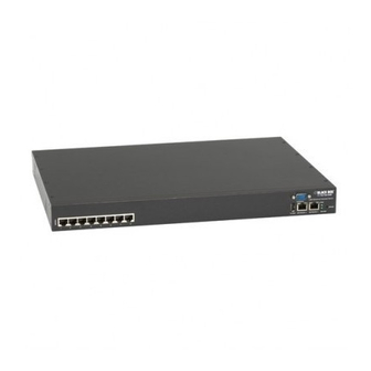
2.1.3 Kit components LES1108A Console Server LES1108A Console Server (2) UTP CAT5 blue cables DB9F-RJ45S straight and DB9F-RJ45S cross-over connectors 5-VDC, 2.0A, Power Supply with IEC Socket and AC power cable Printed Quick Start Guide and this User‘s Manual on CD-ROM Power connection 2.2.1... -
Page 18: Les1108A Power
LES1108A. Network connection The RJ-45 LAN ports are located on the rear panel of the LES1108A and on the front panel of the rack- mount console servers. Use industry standard Cat5 cabling and connectors. Make sure that you only connect the LAN port to an Ethernet network that supports 10BASE-T/100BASE-T. To initially configure the console server, you must connect a PC or workstation to the console server’s principal network port... -
Page 19: Usb Port Connection
RS-232C (EIA-232). Black Box supplies a range of cables and adapters that may be required to connect to the more popular servers and network appliances. Call Technical Support at 724-746-5500 for details. -
Page 20: System Configuration
Chapter 3 Initial System Configuration SYSTEM CONFIGURATION Introduction This chapter provides step-by-step instructions for the console server’s initial configuration, and for connecting it to the Management or Operational LAN. The Administrator must: Activate the Management Console. Change the Administrator password. ... -
Page 21: Browser Connection
o Subnet mask: 255.255.255.0 If you want to retain your existing IP settings for this network connection, click Advanced and Add the above as a secondary IP connection. If it is not convenient to change your PC/workstation network address, you can use the ARP-Ping command to reset the console server IP address. -
Page 22: Administrator Password
(Chapter After completing each of the above steps, you can return to the configuration list by clicking in the top left corner of the screen on the Black Box logo. Note If you are not able to connect to the Management Console at 192.168.0.1 or if the default Username/Password were not accepted, then reset your console server (refer to Chapter 11). -
Page 23: Network Ip Address
Note: We recommend that you set up a new Administrator user as soon as convenient and log in as this new user for all ongoing administration functions (rather than root). This Administrator can be configured in the admin group with full access privileges through the Serial & Network: Users & Groups menu as detailed in Chapter 4. - Page 24 If you selected DHCP, the console server will look for configuration details from a DHCP server on your management LAN. This selection automatically disables any static address. The console server MAC address is printed on a label on the base plate. Note In its factory default state (with no Configuration Method selected) the console server has its DHCP client enabled, so it automatically accepts any network IP address assigned by a DHCP...
-
Page 25: Ipv6 Configuration
3.3.1 IPv6 configuration You can also configure the console server Network and Management LAN Interfaces for IPv6 operation: On the System: IP menu select General Settings page and check Enable IPv6. Then, configure the IPv6 parameters on each Interface page. System Services The Administrator can access and configure the console server and connect to the managed devices using a range of access protocols (services). - Page 26 Select the System: Services option, then select/deselect for the service to be enabled/disabled. The following access protocol options are available: HTTPS This ensures secure browser access to all the Management Console menus. It also allows appropriately configured Users secure browser access to selected Management Console Manage menus.
-
Page 27: Communications Software
Administrator (and User) PC/workstation. Black Box provides the SDT Connector Java applet as the recommended client software tool. You can use other generic tools such as PuTTY and SSHTerm. These tools are all described below as well. -
Page 28: Putty
SDT Connector can be installed on Windows 2000, XP, 2003, Vista PCs, and on most Linux, UNIX, and Solaris computers. 3.5.2 PuTTY You can also use communications packages like PuTTY to connect to the console server command line (and to connect serially attached devices as covered in Chapter 4). PuTTY is a freeware implementation of Telnet and SSH for Windows and UNIX platforms. -
Page 29: Management Network Configuration (Les1208A, Les1216A And Les1248A Only)
Management network configuration (LES1208A, LES1216A and LES1248A only) The LES1208A, LES1216A, and LES1248A console servers have a second network port that you can configure as a management LAN port or as a failover/ OOB access port. 3.6.1 Enable the Management LAN The LES1208A, LES1216A, and LES1248A console servers provide a firewall, router, and DHCP server. -
Page 30: Configure The Dhcp Server
Note You can configure the second Ethernet port as either a gateway port or as an OOB/Failover port (but not both). Make sure you did not allocate Network 2 as the Failover Interface when you configured the principal Network connection on the System: IP menu. The management gateway function is now enabled with default firewall and router rules. - Page 31 Enter the Gateway address that you want to issue to the DHCP clients. If you leave this field blank, the console server’s IP address will be used. Enter the Primary DNS and Secondary DNS address to issue the DHCP clients. If you leave this field blank, the console server’s IP address is used.
-
Page 32: Select Failover Or Broadband Oob
The DHCP server also supports pre-assigning IP addresses to be allocated only to specific MAC addresses and reserving IP addresses to be used by connected hosts with fixed IP addresses. To reserve an IP addresses for a particular host: Click Add in the Reserved Addresses field. ... -
Page 33: Bridging The Network Ports
o the internal modem, or o an external serial modem connected to the Console port (for dialing out to an ISP or the remote management office). Click Apply. You have selected the failover method. It is not active until you specify the external sites to be probed to trigger failover, and set up the failover ports themselves. - Page 34 Select Enable Bridging on the System: IP General Settings menu. All the Ethernet ports are all transparently connected at the data link layer (layer 2) and they are configured collectively using the Network Interface menu. When bridging is enabled, network traffic is forwarded between all Ethernet ports with no firewall restrictions.
-
Page 35: Serial Port And Network Host
SERIAL PORT AND NETWORK HOST Introduction The Black Box console server enables access and control of serially attached devices and network attached devices (hosts). The Administrator must configure access privileges for each of these devices, and specify the services that can be used to control the devices. The Administrator can also set up new users and specify each user’s individual access and control privileges. -
Page 36: Common Settings
SDT Mode enables graphical console access (with RDP, VNC, HTTPS, etc.) to hosts that are serially connected. Terminal Server Mode sets the serial port to wait for an incoming terminal login session. Serial Bridge Mode enables transparently interconnects two serial port devices over a network. ... -
Page 37: Console Server Mode
Specify a label for the port. Select the appropriate Baud Rate, Parity, Data Bits, Stop Bits, and Flow Control for each port. (Note: The RS-485/RS-422 option is not relevant for console servers.) Before proceeding with further serial port configuration, connect the ports to the serial devices they will be controlling, and make sure they have matching settings. - Page 38 Logging Level This specifies the level of information to be logged and monitored (referto Chapter 7— Alerts and Logging). Telnet When the Telnet service is enabled on the console server, a Telnet client on a User or Administrator’s computer can connect to a serial device attached to this serial port on the console server.
- Page 39 If the remote communications are tunneled with SDT Connector, then you can use Telnet to securely access these attached devices (refer to the Note below). Note In Console Server mode, Users and Administrators can use SDT Connector to set up secure Telnet connections that are SSH tunneled from their client PC/workstations to the serial port on the console server.
- Page 40 PuTTY can be downloaded at http://www.tucows.com/preview/195286.html We recommend that you use SSH as the protocol where the User or Administrator connects to the console server (or connects through the console server to the attached serial consoles) over the Internet or any other public network. This will provide authenticated SSH communications between the SSH client program on the remote user’s computer and the console server, so the user’s communication with the serial device attached to the console server is secure.
- Page 41 For a User named “fred” to access serial port 2, when setting up the SSHTerm or the PuTTY SSH client, instead of typing username = fred and ssh port = 3002, the alternate is to type username = fred:port02 (or username = fred:ttyS1) and ssh port = 22. Or, by typing username=fred:serial and ssh port = 22.
-
Page 42: Sdt Mode
Accumulation Period By default, once a connection is established for a particular serial port (such as a RFC2217 redirection or Telnet connection to a remote computer) then any incoming characters on that port are forwarded over the network on a character by character basis. The accumulation period changes this by specifying a period of time that incoming characters will be collected before then being sent as a packet over the network. -
Page 43: Device (Rpc, Ups, Emd) Mode
For configuration details, refer to Chapter 6.6—Using SDT Connector to Telnet or SSH connect to devices that are serially attached to the console server. 4.1.4 Device (RPC, UPS, EMD) Mode This mode configures the selected serial port to communicate with a serial controlled Uninterruptable Power Supply (UPS), Remote Power Controller/Power Distribution Unit (RPC) or Environmental Monitoring Device (EMD). -
Page 44: Syslog
Select Serial Bridging Mode and specify the IP address of the Server console server and the TCP port address of the remote serial port (for RFC2217 bridging this will be 5001-5048). By default, the bridging client will use RAW TCP. Select RFC2217 if this is the console server mode you have specified on the server console server. -
Page 45: Add/ Edit Users
Add/ Edit Users The Administrator uses this menu selection to set up, edit, and delete users, and to define the access permissions for each of these users. Users can be authorized to access specified console server serial ports and specified network-attached hosts. - Page 46 the Administrator can also set up users who are not a member of any Groups. They will have the same access as users in the additional groups. To set up new Groups and new users, and to classify users as members of particular Groups: ...
-
Page 47: Authentication
Click Apply. The new user can now access the Network Devices, Ports, and RPC Outlets you nominated as accessible. Plus, if the user is a Group member they can also access any other device/port/outlet that was set up as accessible to the Group. Note There are no specific limits on the number of users you can set up;... -
Page 48: Trusted Networks
Enter the IP Address or DNS Name and a Host Name (up to 254 alphanumeric characters) for the new network connected Host (and optionally enter a Description). Add or edit the Permitted Services (or TCP/UDP port numbers) that are authorized to be used in controlling this host. - Page 49 Select Serial & Network: Trusted Networks. To add a new trusted network, select Add Rule. Select the Accessible Port(s) that the new rule is to be applied to. Then, enter the Network Address of the subnet to be permitted access. ...
-
Page 50: Serial Port Cascading
Slave units appear as if they are part of the Master. Black Box’s clustering connects each Slave to the Master with an SSH connection. This uses public key authentication so the Master can access each Slave using the SSH key pair (rather than using passwords). -
Page 51: Manually Generate And Upload Ssh Keys
Next, you must select whether to generate keys using RSA and/or DSA (if unsure, select only RSA). Generating each set of keys will require approximately two minutes, and the new keys will destroy any old keys of that type that may previously been uploaded. Also, while the new generation is underway on the master, functions relying on SSH keys (for example, cascading) may stop functioning until they are updated with the new set of keys. - Page 52 Next, you must register the Public Key as an Authorized Key on the Slave. In a case that has only one Master with multiple Slaves, you only need to upload the one RSA or DSA public key for each Slave. Note Using key pairs can be confusing since one file (Public Key) fulfills two roles—...
-
Page 53: Configure The Slaves And Their Serial Ports
If the system asks you to supply a password, then there is a problem with uploading keys. The keys should remove any need to supply a password. 4.6.3 Configure the slaves and their serial ports You can now begin setting up the Slaves and configuring Slave serial ports from the Master console server: ... -
Page 54: Managing The Slaves
Select the appropriate Serial & Network: Users & Groups to add new users with access privileges to the Slave serial ports (or to extend existing users’ access privileges). Select the appropriate Serial & Network: Trusted Networks to specify network addresses that can access nominated Slave serial ports . -
Page 55: Managed Devices
Remote Console Server Retail data systems Remote Console Server Serial device applications Building automation Remote Console systems Server Serial/IP redirector virtual COM ports Controllers Sensors This serial port redirector software is loaded in your desktop PC, and it allows you to use a serial device that’s connected to the remote console server as if it were connected to your local serial port. - Page 56 Select the connection type for the new connection (Serial, Network Host, UPS, or RPC) and then select the specific connection from the presented list of configured unallocated hosts/ports/outlets. To add a new network-connected Managed Device: The Administrator adds a new network-connected Managed Device using Add Host on the Serial &...
- Page 57 Click Add Connection and select Serial and the Port that connects to the Managed Device. To add a UPS/RPC power connection or network connection or another serial connection, click Add Connection. Click Apply. Note To set up a new serially connected RPC UPS or EMD device, configure the serial port, designate it as a Device, then enter a Name and Description for that device in the Serial &...
-
Page 58: Failover And Oob Dial-In
PC Card Modem tab will appear under System -> Dial. The LES1108A, LES1116A, and LES1148A models need to have an external modem attached via a serial cable to the DB9 port marked Local (located on the front of the unit). -
Page 59: Configure Dial-In Ppp
5.1.1 Configure Dial-In PPP To enable dial-in PPP access on the modem: Select the System: Dial menu option and the port to be configured (Serial DB9 Port or Internal Modem Port). Note The console server console/modem serial port is set by default to 115200 baud, No parity, 8 data bits and 1 stop bit, with software (Xon-Xoff) flow control enabled for the Serial DB9 Port and 9600 baud for the Internal modem and PC Card Ports. - Page 60 You must select the Authentication Type to apply to the dial-in connection. The console server uses authentication to challenge Administrators who dial-in to the console server. (For dial-in access, the username and password received from the dial-in client are verified against the local authentication database stored on the console server).
-
Page 61: Using Sdt Connector Client
5.1.2 Using SDT Connector client Administrators can use their SDT Connector client to set up secure OoB dial-in access to all their remote console servers. With a point and click, you can initiate a dial up connection. Refer to Chapter 6.5. 5.1.3 Set up Windows XP/ 2003/Vista/7 client ... -
Page 62: Set Up Earlier Windows Clients
5.1.4 Set up earlier Windows clients For Windows 2000, the PPP client set up procedure is the same as above, except you get to the Dial-Up Networking Folder by clicking the Start button and selecting Settings. Then, click Network and Dial-up Connections and click Make New Connection. ... -
Page 63: Dial-Out Failover
When configuring the principal network connection, specify Network 2 (eth1) as the Failover Interface to use when a fault is detected with Network 1 (eth0). Specify the Probe Addresses of two sites (the Primary and Secondary) that the Advanced Console ... - Page 64 Specify the Probe Addresses of two sites (the Primary and Secondary) that the console server is to ping to determine if Network1 is still operating. Select the System: Dial menu option and the port to be configured (Serial DB9 Port or Internal ...
-
Page 65: Secure Ssh Tunneling And Sdt Connector
SECURE SSH TUNNELING AND SDT CONNECTOR Introduction Each Black Box console server has an embedded SSH server and uses SSH tunneling so remote users can securely connect through the console server to Managed Devices—using text-based console tools (such as SSH, telnet, SoL) or graphical tools (such VNC, RDP, HTTPS, HTTP, X11, VMware, DRAC, iLO). -
Page 66: Configuring For Ssh Tunneling To Hosts
Groups. SDT Connector Client Configuration The SDT Connector client works with all Black Box console servers. Each of these remote console servers has an embedded OpenSSH based server that you can configure to port forward connections from the SDT Connector client to hosts on their local network (as detailed in the previous chapter). -
Page 67: Sdt Connector Installation
6.2.1 SDT Connector installation The SDT Connector set up program (SDTConnector Setup-1.n.exe or sdtcon-1.n.tar.gz) is included on the CD supplied with your Black Box console server. Run the set-up program. Note For Windows clients, the SDTConnectorSetup-1.n.exe application will install the SDT Connector 1.n.exe and the config file defaults.xml. -
Page 68: Configuring A New Console Server Gateway In The Sdt Connector Client
(refer to Section 6.2.7 and 6.2.9). You can also set up SDT Connector to connect out-of-band to the console server (refer to Section 6.2.9). 6.2.2 Configuring a new console server gateway in the SDT Connector client To create a secure SSH tunnel to a new console server: ... -
Page 69: Auto-Configure Sdt Connector Client With The User's Access Privileges
Or, enter a Descriptive Name to display instead of the IP or DNS address, and any Notes or a Description of this gateway (such as its firmware version, site location, or anything special about its network configuration). Click OK and an icon for the new gateway will now appear in the SDT Connector home page. Note For an SDT Connector user to access a console server (and then access specific hosts or serial devices connected to that console server), that user must first be setup on the console server,... -
Page 70: Make An Sdt Connection Through The Gateway To A Host
Note The Retrieve Hosts function will auto-configure all user classes (that is, they can be members of user or admin or some other group or no group. SDT Connector will not auto-configure the root (and we recommend that you only use this account for initial config and to add an initial admin account to the console server). -
Page 71: Manually Adding Hosts To The Sdt Connector Gateway
Note You can configure the SDT Connector client can be configured with unlimited number of Gateways (that is, console servers). You can configure each Gateway to port forward to an unlimited number of locally networked Hosts. There is no limit on the number of SDT Connector clients that can be configured to access the one Gateway. -
Page 72: Manually Adding New Services To The New Hosts
6.2.6 Manually adding new services to the new hosts To extend the range of services that you can use when accessing hosts with SDT Connector: Select Edit: Preferences and click the Services tab. Click Add. Enter a Service Name and click Add. ... - Page 73 An example is the Dell RAC service. The first redirection is for the HTTPS connection to the RAC server— it has a client associated with it (web browser) that it launches immediately when you click the button for this service. The second redirection is for the VNC service that you may choose to later launch from the RAC web console.
-
Page 74: Adding A Client Program To Be Started For The New Service
Note SDT Connector can also tunnel UDP services. SDT Connector tunnels the UDP traffic through the TCP SSH redirection, so it is a ―tunnel within a tunnel.‖ Enter the UDP port where the service is running on the host. This will also be the local UDP port that SDT Connector binds as the local endpoint of the tunnel. - Page 75 Enter a Name for the client. Enter the Path to the executable file for the client (or click Browse to locate the executable). Enter a Command Line associated with launching the client application. SDT Connector typically launches a client using command line arguments to point it at the local endpoint of the redirection.
-
Page 76: Dial In Configuration
Click OK. 6.2.8 Dial in configuration If the client PC is dialing into Local/Console port on the console server, you will need to set up a dial-in PPP link: Configure the console server for dial-in access (following the steps in the Configuring for Dial-In PPP Access section in Chapter 5, Configuring Dial In Access). -
Page 77: Sdt Connector - Telnet Or Ssh Connect To Serially Attached Devices
Browse to the console server and select Network Hosts from Serial & Network, click Add Host, and in the IP Address/DNS Name field enter 127.0.0.1 (this is the Black Box network loopback address). Then, enter Loopback in Description. - Page 78 Apply. Select Network Hosts from Serial & Network and click Add Host. In the IP Address/DNS Name field enter 127.0.0.1 (this is the Black Box network loopback address) and enter Loopback in Description.
-
Page 79: Using Sdt Connector For Out-Of-Band Connection To The Gateway
Using SDT Connector for out-of-band connection to the gateway You can also set up SDT Connector to connect to the console server (gateway) out-of-band (OoB). OoB access uses an alternate path for connecting to the gateway to that used for regular data traffic. OoB access is useful for when the primary link into the gateway is unavailable or unreliable. -
Page 80: Importing (And Exporting) Preferences
pon network_connection where network_connection is the name of the connection. Enter the command or path to a script to stop the OoB connection in Stop Command. To stop a pre-configured dial-up connection under Windows, use the following Stop Command: cmd /c start "Stopping Out of Band Connection"... -
Page 81: Sdt Connector Public Key Authentication
The Microsoft Remote Desktop Protocol (RDP) enables the system manager to securely access and manage remote Windows computers—to reconfigure applications and user profiles, upgrade the server’s operating system, reboot the machine, etc. Black Box’s Secure Tunneling uses SSH tunneling, so this RDP traffic is securely transferred through an authenticated and encrypted tunnel. -
Page 82: Enable Remote Desktop On The Target Windows Computer To Be Accessed
SDT with RDP also allows remote Users to connect to Windows XP, Vista, Server2003, and Server 2008 computers and to Windows 2000 Terminal Servers; and to access to all of the applications, files, and network resources (with full graphical interface just as though they were in front of the computer screen at work). -
Page 83: Configure The Remote Desktop Connection Client
To set the user(s) who can remotely access the system with RDP, click Add on the Remote Desktop Users dialog box. Note If you need to set up new users for Remote Desktop access, open User Accounts in the Control Panel and follow the steps to nominate the new user‘s name, password, and account type (Administrator or Limited). - Page 84 In Computer, enter the appropriate IP Address and Port Number: Where there is a direct local or enterprise VPN connection, enter the IP Address of the console server, and the Port Number of the SDT Secure Tunnel for the console server serial port that you attach to the Windows computer you want to control.
- Page 85 Note The Remote Desktop Connection software is pre-installed with Windows XP, Vista and Server 2003/2008. For earlier Windows PCs, you need to download the RDP client: Go to the Microsoft Download Center site http://www.microsoft.com/downloads/details.aspx?familyid=80111F21-D48D-426E-96C2- 08AA2BD23A49&displaylang=en and click the Download button This software package will install the client portion of Remote Desktop on Windows 95, Windows 98 and 98 Second Edition, Windows Me, Windows NT 4.0, and Windows 2000.
- Page 86 Note The rdesktop client is supplied with Red Hat 9.0: rpm -ivh rdesktop-1.2.0-1.i386.rpm For Red Hat 8.0 or other distributions of Linux; download source, untar, configure, make, make, then install. rdesktop currently runs on most UNIX based platforms with the X Window System and can be downloaded from http://www.rdesktop.org/ C.
-
Page 87: Sdt Ssh Tunnel For Vnc
SDT SSH Tunnel for VNC With SDT and Virtual Network Computing (VNC), Users and Administrators can securely access and control Windows 98/NT/2000/XP/2003, Linux, Macintosh, Solaris, and UNIX computers. There’s a range of popular free and commercial VNC software available (UltraVNC, RealVNC, TightVNC). To set up a secure VNC connection, install and configure the VNC Server software on the computer the user will access, then install and configure the VNC Viewer software on the Viewer PC. -
Page 88: Install, Configure And Connect The Vnc Viewer
To set up a persistent VNC server on Red Hat Enterprise Linux 4: o Set a password using vncpasswd o Edit /etc/sysconfig/vncservers o Enable the service with chkconfig vncserver on o Start the service with service vncserver start o Edit /home/username/.vnc/xstartup if you want a more advanced session than just twm and an xterm. - Page 89 A. When the Viewer PC is connected to the console server thru an SSH tunnel (over the public Internet, or a dial-in connection, or private network connection), enter localhost (or 127.0.0.1) as the IP VNC Server IP address; and the source port you entered when setting SSH tunneling /port forwarding (in Section 6.2.6) e.g.
-
Page 90: Using Sdt To Ip Connect To Hosts That Are Serially Attached To The Gateway
Note For general background reading on Remote Desktop and VNC access we recommend the following: The Microsoft Remote Desktop How-To. http://www.microsoft.com/windowsxp/using/mobility/getstarted/remoteintro.mspx The Illustrated Network Remote Desktop help page. http://theillustratednetwork.mvps.org/RemoteDesktop/RemoteDesktopSetupandTroubleshooting.ht What is Remote Desktop in Windows XP and Windows Server 2003? by Daniel Petri. http://www.petri.co.il/what's_remote_desktop.htm ... - Page 91 Windows 2003 and Windows XP Professional allow you to create a simple dial in service which can be used for the Remote Desktop/VNC/HTTP/X connection to the console server: Open Network Connections in Control Panel and click the New Connection Wizard. ...
- Page 92 Specify which Users will be allowed to use this connection. This should be the same Users who were given Remote Desktop access privileges in the earlier step. Click Next. On the Network Connection screen select TCP/IP and click Properties. ...
-
Page 93: Set Up Sdt Serial Ports On Console Server
Note The above notes describe setting up an incoming connection for Windows XP. The steps are similar for Vista and Windows Server 2003/2008, but the set up screens present slightly differently: You need to put a check in the box for Always allow directly connected devices such as palmtop….. -
Page 94: Set Up Sdt Connector To Ssh Port Forward Over The Console Server Serial Port
Select the Serial & Network: Serial Port menu option and click Edit (for the particular Serial Port that is connected to the Windows computer COM port). On the SDT Settings menu, select SDT Mode (this will enable port forwarding and SSH tunneling) and enter a Username and User Password. - Page 95 SSH Tectia is leading end-to-end commercial communications security solution for the enterprise. Reflection for Secure IT (formerly F-Secure SSH) is another good commercial SSH-based security solution. For example, the steps below show how to establish an SSH tunneled connection to a network connected device using the PuTTY client software.
- Page 96 be accessed using SSH tunneling (except by the root” user who can tunnel to any IP address “ the console server can route to). If your destination computer is serially connected to the console server, set the Destination as <port label>:3389. For example, if the Label you specified on the serial port on the console server is win2k3, then specify the remote host as win2k3:3389.
- Page 97 If you are connecting as an Administrator (in the “admin” group), then you can connect to any configured Host or Serial Ports (that has SDT enabled). To set up the secure SSH tunnel for a HTTP browser connection to the Managed Device, specify port 80 (instead of port 3389 that was used for RDP) in the Destination IP address.
-
Page 98: Alerts And Logging
Chapter 7 Alerts and Logging ALERTS AND LOGGING Introduction This chapter describes the alert generation and logging features of the console server. The Alert facility monitors the serial ports, all logins, the power status, and environmental monitors and probes, and sends emails, SMS, Nagios, or SNMP alerts when specified trigger events occur. -
Page 99: Sms Alerts
In the SMTP Server field, enter the outgoing mail Server’s IP address. If this mail server uses a Secure Connection, specify its type. You may enter a Sender email address which will appear as the “from” address in all email notifications sent from this console server. -
Page 100: Snmp Alerts
In the SMTP SMS Server field in the Alerts & Logging: SMTP &SMS menu, enter the IP address of the outgoing mail Server (and Secure Connection if applicable). You may enter a Sender email address, which will appear as the “from” address in all email notifications sent from this console server. -
Page 101: Nagios Alerts
To configure for SNMP v3, you will need to enter an ID and authentication password and contact information for the local Administrator (in the Security Name). Click Apply to activate SNMP. Note All console servers have the snmptrap daemon to send traps/notifications to remote SNMP servers on defined trigger events as detailed above. -
Page 102: Add A New Alert
Select Alerts & Logging: Alerts, which will display all the alerts currently configured. Click Add Alert. 7.2.1 Add a new alert The first step is to specify the alert service that this event will use for sending notification, who to notify there, and what port/host/device is to be monitored: ... -
Page 103: Configuring General Alert Types
7.2.2 Configuring general alert types Next, you must select the Alert Type (Connection, Signal, Pattern Match, UPS Power Status, Environment and Power Sensor or Alarm Sensor) to monitor. You can configure a selection of different Alert types and any number of specific triggers. ... -
Page 104: Configuring Environment And Power Alert Type
UPS Power Status Alert— This alert will be triggered when the UPS power status changes between on line, on battery, and low battery. This status will only be monitored on the Applicable UPS(es) you select. Environment and Power Alert—(next section). ... -
Page 105: Configuring Alarm Sensor Alert Type
Specify the applicable UPSes, RPCs (and RPC outlets), and Environmental Sensors to Apply Alert Note An alert notification (SNMP, SMTP etc) is only sent out when there is a transition to or from a trigger event/level. For example, if a High temperature alert is set at 40 degrees with a 5 degree hysteresis then an High alert notification will be sent when the sensor temperature reads 40 degrees. -
Page 106: Serial Port Logging
Serial Port Logging In Console Server mode, activity logs of all serial port activity can be maintained. These records are stored on an off-server, or in the Advanced Console Server flash memory. To specify which serial ports have activities recorded and to what level data is to be logged: ... - Page 107 For each Host, when you set up the Permitted Services that you authorize to use, you also must set up the level of logging to maintain for each service. Specify the logging level to maintain for that particular TDC/UDP port/service, on that particular Host: Level 0 Turns off logging for the selected TDC/UDP port to the selected Host.
-
Page 108: Power & Environmental Management
POWER & ENVIRONMENTAL MANAGEMENT Introduction Black Box console servers manage embedded software that you can use to manage connected Power Distribution Systems (PDUs), IPMI devices, and Uninterruptible Power Supplies (UPSs) supplied by a number of vendors, and some environmental monitoring devices. - Page 109 Select the Serial & Network: RPC Connections menu. This will display all the RPC connections that have already been configured. Click Add RPC. Connected Via presents a list of serial ports and network Host connections that you have set up with device type RPC (but have yet to connect to a specific RPC device): ...
- Page 110 SNMP RPC Types currently supported by the embedded Network UPS Tools. If you are connecting to the RPC by a serial port, you will be presented with all the serial RPC types currently supported by the embedded PowerMan and the Black Box power manager: _____________________________________________________________________ Page 110 724-746-5500 | b lackb o x.co m...
-
Page 111: Rpc Access Privileges And Alerts
RPC Type or will query the RPC itself for this information. Note The Black Box console servers support most popular network and serial PDUs. If your PDU is not on the default list, then you can add support directly (as covered in Chapter 14—Advanced Configurations) or add the PDU support to either the Network UPS Tools or PowerMan open source projects. -
Page 112: Rpc Status
Power screen. Uninterruptible Power Supply Control (UPS) You can configure all Black Box console servers to manage locally and remotely connected UPS hardware using Network UPS Tools. Network UPS Tools (NUT) is a group of open source programs that provide a common interface for monitoring and administering UPS hardware. -
Page 113: Managed Ups Connections
Console Server Multiple local (serial USB networked) UPSs Managed Multiple remote UPSs 8.2.1 Managed UPS connections A Managed UPS is a UPS that is directly connected as a Managed Device to the console server. You can connect it via serial or USB cable or by the network. The console server becomes the master of this UPS, and runs a upsd server to allow other computers that are drawing power through the UPS (slaves) to monitor the UPS status and take appropriate action, such as shutdown when the UPS battery is low. - Page 114 For serial UPSes attach the UPS to the selected serial port on the console server. From the Serial and Network: Serial Port menu, configure the Common Settings of that port with the RS-232 properties, etc. required by the UPS (refer to Chapter 4.1.1—Common Settings). Then select UPS as the Device Type.
- Page 115 Select if the UPS will be Connected Via USB, over a pre-configured serial port, or via SNMP/HTTP/HTTPS over the preconfigured network Host connection. When you select a network UPS connection, then the corresponding Host Name/Description that you set up for that connection will be entered as the Name and Description for the power device.
-
Page 116: Remote Ups Management
(but not managed) by your console server. You can configure the upsc and upslog clients in the Black Box console server to monitor remote servers that are running Network UPS Tools managing their locally connected UPSes. These remote servers might be other Black Box console servers or generic Linux servers running NUT. -
Page 117: Controlling Ups Powered Computers
Enter the IP Address or DNS name of the remote console server* that is managing the remote UPS. (*This may be another Black Box console server or it may be a generic Linux server running Network UPS Tools.) Note An example where centrally monitor remotely distributed UPSes is useful is a campus or large business site where there‘s a multitude of computer and other equipment sites spread afar, each... -
Page 118: Ups Alerts
MONITOR managedups@192.168.0.1 1 username password slave - managedups is the UPS Name of the Managed UPS - 192.168.0.1 is the IP address of the Black Box console server - 1 indicates the server has a single power supply attached to this UPS... -
Page 119: Overview Of Network Ups Tools (Nut)
Click on any particular All Data for any UPS System in the table for more status and configuration information about the selected UPS System. Select UPS Logs and you will be presented with the log table of the load, battery charge level, temperature, and other status information from all the Managed and Monitored UPS systems. - Page 120 (open source software from Livermore Labs that also is embedded in Black Box console servers). These NUT clients and servers all are embedded in each Black Box console server (with a Management Console presentation layer added) —and they also are run remotely on distributed console servers and other remote NUT monitoring systems.
-
Page 121: Environmental Monitoring
Environmental Monitoring The Environmental Monitor Device (EMD) connects to any Black Box console server serial port and each console server can support multiple EMDs. Each EMD device has one temperature and one humidity sensor and one or two general-purpose status sensors that you can connect to a smoke detector, water detector, vibration, or open-door sensor. -
Page 122: Connecting The Emd
EMD. You can only use the EMD with a Black Box console server; you cannot connect it to standard RS-232 serial ports on other appliances. Select Environmental as the Device Type in the Serial & Network: Serial Port menu for the port to which the EMD will be attached. -
Page 123: Environmental Alerts
Enter a Name and optionally a Description for the EMD and select the pre-configured serial port that the EMD will be Connected Via. You may optionally calibrate the EMD with a Temperature Offset (+ or - °C) or Humidity Offset (+ or percent). - Page 124 _____________________________________________________________________ Page 124 724-746-5500 | b lackb o x.co m...
-
Page 125: Authentication
Chapter 9 Authentication AUTHENTICATION Introduction The console server is a dedicated Linux computer with a myriad of popular and proven Linux software modules for networking, secure access (OpenSSH), and communications (OpenSSL), and sophisticated user authentication (PAM, RADIUS, TACACS+ and LDAP). ... -
Page 126: Local Authentication
TACACS /RADIUS/LDAP Down Local: Tries remote authentication first, falling back to local if the remote authentication returns an error condition (for example, if the remote authentication server is down or inaccessible). 9.1.1 Local authentication Select Serial and Network: Authentication and check Local. ... -
Page 127: Radius Authentication
http://www.cisco.com/en/US/products/sw/secursw/ps4911/products_user_guide_chapter09186a0 0800eb6d6.html http://cio.cisco.com/univercd/cc/td/doc/product/software/ios113ed/113ed_cr/secur_c/scprt2/sctplu s.htm 9.1.3 RADIUS authentication Perform the following procedure to configure the RADIUS authentication method to use whenever the console server or any of its serial ports or hosts is accessed: Select Serial and Network: Authentication and check RADIUS or LocalRADIUS or RADIUSLocal or RADIUSDownLocal. -
Page 128: Ldap Authentication
Users may be added to the local console server appliance. If they are not added and they log in via remote AAA, a user will be added for them. This user will not show up in the Black Box configurators unless they are specifically added, at which point they are transformed into a completely local user. -
Page 129: Pam (Pluggable Authentication Modules)
If a local user logs in, they may be authenticated/authorized from the remote AAA server, depending on the chosen priority of the remote AAA. A local user’s authorization is the union of local and remote privileges. Example 1: User Tim is locally added, and has access to ports 1 and 2. He is also defined on a remote TACACS server, which says he has access to ports 3 and 4. - Page 130 Authorization via TACACS for both serial ports and host access: Permission to access resources may be granted via TACACS by indicating a Black Box Appliance and a port or networked host the user may access. (See the example configuration files below for example.)
-
Page 131: Ssl Certificate
SSL Certificate The console server uses the Secure Socket Layer (SSL) protocol for encrypted network traffic between itself and a connected user. When establishing the connection, the console server has to expose its identity to the user’s browser using a cryptographic certificate. The default certificate that comes with the console server device upon delivery is for testing purposes only. - Page 132 Select System: SSL Certificate and fill out the fields as explained below: Common name This is the network name of the console server once it is installed in the network (usually the fully qualified domain name). It is identical to the name that is used to access the console server with a web browser (without the “http://”...
- Page 133 After completing these steps, the console server has its own certificate that is used for identifying the console server to its users. Note You can find information on issuing certificates and configuring HTTPS from the command line in Chapter 15. _____________________________________________________________________ Page 133 724-746-5500 | b lackb o x.co m...
-
Page 134: Nagios Integration
Chapter 10 Nagios Integration NAGIOS INTEGRATION Introduction Nagios is a powerful, highly extensible open source tool for monitoring network hosts and services. The core Nagios software package will typically be installed on a server or virtual server, the central Nagios server. -
Page 135: Central Management And Setting Up Sdt For Nagios
Assign contact groups who are responsible for specific services in specific time frames. 10.2 Central management and setting up SDT for Nagios The Black Box Nagios solution has three parts: the Central Nagios server, Distributed Black Box console servers, and the SDT for Nagios software. -
Page 136: Set Up Central Nagios Server
Note that you will need the core Nagios server package, and at least one of the NRPE or NSCA add-ons. NSCA is required to use the alerting features of the Black Box distributed hosts, installing both NRPE and NSCA is recommended. - Page 137 Enter the Host Name and the Nagios Host Address (for example, IP address) that the central Nagios server will use to contact the distributed Black Box console server. Enter the IP address that the distributed Black Box console server will use to contact the central Nagios server in Nagios Server Address.
- Page 138 Scroll down to Nagios Settings and check Enable Nagios. Click New Check and select Check Ping. Click check-host-alive. Click New Check and select Check Permitted TCP. Select Port 3389 Click New Check and select Check TCP. Select Port 80. ...
-
Page 139: Configuring Nagios Distributed Monitoring
In Username, enter: sdtnagiosuser, then enter and confirm a Password. In Accessible Hosts click the IP address/DNS name of the IIS server, and in Accessible Ports click the serial port that has the router console port attached. Click Apply. 10.3 Configuring Nagios distributed monitoring To activate the console server Nagios distributed monitoring: ... -
Page 140: Enable Nrpe Monitoring
10.3.2 Enable NRPE monitoring Serial Tunneled check_serial Nagios check_nrpe NRPE Network check_tcp Nagios monitoring host Remote Console Server Remote managed devices Enabling NRPE allows you to execute plug-ins (such as check_tcp and check_ping) on the remote Console server to monitor serial or network attached remote servers. This will offload CPU load from the upstream Nagios monitoring machine. -
Page 141: Configure Selected Serial Ports For Nagios Monitoring
Select the Encryption to be used from the drop down menu, then enter a Secret password and specify a check Interval. Refer to the sample Nagios configuration section below for some examples of configuring specific NSCA checks. 10.3.4 Configure Selected Serial Ports for Nagios Monitoring The individual Serial Ports connected to the console server to be monitored must be configured for Nagios checks. -
Page 142: Configure The Upstream Nagios Monitoring Host
NSCA as a primary method, falling back to NRPE if a check was late— for details see the Nagios documentation (http://www.nagios.org/docs/) on Service and Host Freshness Checks. ; Host definitions ; Black Box console server define host{ generic-host... - Page 143 NRPE Daemon host_name Black Box generic-service check_command check_nrpe_daemon ; Serial Status define command { command_name check_serial_status command_line $USER1$/check_nrpe -H 192.168.254.147 -p 5666 -c check_serial_$HOSTNAME$ define service { service_description Serial Status host_name server generic-service check_command check_serial_status define service { service_description...
- Page 144 0 passive_checks_enabled define servicedependency{ name Black Box_nrpe_daemon_dep host_name Black Box dependent_host_name server dependent_service_description Port Log service_description NRPE Daemon execution_failure_criteria w,u,c ; Ping define command{ command_name check_ping_via_Black Box command_line $USER1$/check_nrpe -H 192.168.254.147 -p 5666 -c host_ping_$HOSTNAME$...
-
Page 145: Basic Nagios Plug-Ins
Each console server is preconfigured with two checks that are specific to Black Box: _____________________________________________________________________ Page 145... -
Page 146: Additional Plug-Ins
check_serial_signals is used to monitor the handshaking lines on the serial ports check_port_log is used to monitor the data logged for a serial port. 10.4.3 Additional plug-ins Additional Nagios plug-ins (listed below) are available for Advanced Console Servers (LES1208A, LES1216A, LES1248A: check_apt check_by_ssh check_clamd... -
Page 147: Distributed Monitoring Usage Scenarios
Time 3DES SSH tunnel encryption NSCA for single check ~ ½ second ~ ½ second ~ ½ second NSCA for 100 sequential checks 100 seconds 100 seconds 100 seconds NSCA for 10 sequential checks, batched upload 1 ½ seconds 2 seconds 1 second NSCA for 100 sequential checks, batched upload 7 seconds 11 seconds... - Page 148 PC running Network checks over Ethernet NAGIOS Serial checks over RS-232 Power monitoring and manipulation via IPDU Console Hosts Server Remote site In this scenario, configure the console server NRPE server or NSCA client to actively check configured services and upload the checks to the Nagios server that’s waiting passively. You can also configure it to service NRPE commands to perform checks on demand.
- Page 149 PC running SSH travel initiated for remote site NAGIOS NRPE server at branch server‘s request Internet Console server Remote site with no network access In this scenario the console server allows dial-in access for the Nagios server. Periodically, the Nagios server will establish a connection to the console server and execute any NRPE commands, before dropping the connection.
-
Page 150: System Management
Chapter 11 System Management SYSTEM MANAGEMENT Introduction This chapter describes how the Administrator can perform a range of general console server system administration and configuration tasks such as: Applying Soft and Hard Resets to the gateway. Re-flashing the Firmware. ... -
Page 151: Upgrade Firmware
Or select Status: Support Report and note the Firmware Version. To upgrade, you first must download the latest firmware image from the Black Box.web site. Save this downloaded firmware image file to a system on the same subnet as the console server. -
Page 152: Configure Date And Time
Click Apply and the console server appliance will perform a soft reboot and start upgrading the firmware. This process will take several minutes. After the firmware upgrade completes, click here to return to the Management Console. Your console server will have retained all its pre-upgrade configuration information. 11.3 Configure Date and Time We recommend that you set the local Date and Time in the console server as soon as it is configured. -
Page 153: Configuration Backup
Enter the IP address of the remote NTP Server and click Apply. You must now also specify your local time zone so the system clock can show local time (and not UTP): Set your appropriate region/locality in the Time Zone selection box and click Apply. 11.4 Configuration Backup We recommend that you back up the console server configuration whenever you make significant changes (such as adding new Users or Managed Devices) or before performing a firmware upgrade. - Page 154 To backup and restore using USB: Make sure the USB flash is the only USB device attached to the console server and click Prepare Storage in the Local Configuration Backup menu. This will set a Volume Label on the USB storage device. This preparation step is only necessary the first time, and will not affect any other information you have saved onto the USB storage device.
- Page 155 Note: Before selecting Load On Erase, make sure that you have tested your alternate default configuration by clicking Restore. If your alternate default configuration causes the console server to not boot, recover your unit to factory settings using the following steps: If the configuration is stored on an external USB storage device, unplug the storage device and reset to factory defaults as per section 11.1 of the user manual.
-
Page 156: Status Reports
Chapter 12 Status Reports STATUS REPORTS Introduction This chapter describes the dashboard feature and the status reports that are available: Port Access and Active Users Statistics Support Reports Syslog Dashboard Other status reports that are covered elsewhere include: ... -
Page 157: Statistics
You can find detailed statistics reports by selecting the various submenus. 12.3 Support Reports The Support Report provides useful status information that will assist the Black Box Technical Support team to solve any problems you may experience with your console server. -
Page 158: Syslog
Select Status: Support Report and you will be presented with a status snapshot. Save the file as a text file and attach it to your support email. 12.4 Syslog The Linux System Logger in the console server maintains a record of all system messages and errors: ... -
Page 159: Configuring The Dashboard
12.5.1 Configuring the Dashboard Only users who are members of the admin group (and the root user) can configure and access the dashboard. To configure a custom dashboard: Select System: Configure Dashboard and select the user (or group) you are configuring this custom dashboard layout for. - Page 160 Click Apply. Note: The Alerts widget is a new screen that shows the current alerts status. When an alert gets triggered, a corresponding .XML file is created in /var/run/alerts/. The dashboard scans all these files and displays a summary status in the alerts widget. When an alert is deleted, the corresponding .XML files that belong to that alert are also deleted.
-
Page 161: Creating Custom Widgets For The Dashboard
12.5.2 Creating custom widgets for the Dashboard T o run a custom script inside a dashboard widget: Create a file called "widget-<name>.sh" in the folder /etc/config/scripts/ where <name> can be anything. You can have as many custom dashboard files as you want. Inside this file you can put any code you want. -
Page 162: Management
Chapter 13 Management MANAGEMENT Introduction The console server has a small number of Manage reports and tools that are available to both Administrators and Users: Access and control authorized devices. View serial port logs and host logs for those devices. ... -
Page 163: Port And Host Logs
13.2 Port and Host Logs Administrators and Users can view logs of data transfers to connected devices. Select Manage: Port Logs and the serial Port # to be displayed. To display Host logs, select Manage: Host Logs and the Host to be displayed. 13.3 Serial Port Terminal Connection Administrator and Users can communicate directly with the console server command line and with devices attached to the console server serial ports using SDT Connector and their local tenet client, or... -
Page 164: Power Management
Click Connect to SDT Connector to access the console server’s command line shell or the serial ports via SDT Connector. This will to activate the SDT Connector client on the computer you are browsing from and load your local telnet client to connect to the command line or serial port using SSH. -
Page 165: Configuration From The Command Line
Black Box provides a number of custom command line utilities and scripts to make it simple to configure the console server and make sure the changes are stored in the console server's flash memory, etc. - Page 166 o If you are connecting over the LAN, then you will need to interconnect the Ethernet ports and direct your terminal emulator program to the IP address of the console server (192.168.0.1 by default). Log on to the console server by pressing “return” a few times. The console server will request a username and password.
- Page 167 -v –verbose Log extra debug information. -d –del=id Remove the given configuration element specified by a '.' separated identifier. -g –get=id Display the value of a configuration element. -p –path=file Specify an alternate configuration file to use. The default file is located at /etc/config/config.xml.
-
Page 168: Serial Port Configuration
Note: The config command does not verify whether the nodes edited/added by the user are valid. This means that any node may be added to the tree. If a user runs the following command: # /bin/config -s config.fruit.apple=sweet The configurator will not complain, but this command is useless. When the configurators are run (to turn the config.xml file into live config) they will simply ignore this <fruit>... - Page 169 Additionally, before any port can function properly, you need to set the port mode. Set any port to run in one of the five possible modes (refer Chapter 4 for details): [Console server mode|Device mode|SDT mode|Terminal server mode|Serial bridge mode]. All these modes are mutually exclusive. Console server mode The command to set the port in portmanager mode: # config -s config.ports.port5.mode=portmanager...
- Page 170 To configure a username and password when accessing this port with Username = user1 and Password = secret: # config -s config.ports.port#.sdt.username=user1 # config -s config.ports.port#.sdt.password=secret Terminal server mode Enable a TTY login for a local terminal attached to serial port 5: # config -s config.ports.port5.mode=terminal # config -s config.ports.port5.terminal=[vt220 | vt102 | vt100 | linux | ansi] The default terminal is vt220.
-
Page 171: Adding And Removing Users
emergency debug critical alert 14.3 Adding and Removing Users First, determine the total number of existing Users (if you have no existing Users you can assume this is # config -g config.users.total This command should display config.users.total 1. Note that if you see config.users.total this means you have 0 Users configured. -
Page 172: Adding And Removing User Groups
# config -s config.ports.port1.power.outlet3.users.total=2 (total number of users that have access to this outlet) more users given access this power outlet, then increment 'config.ports.port1.power.outlet3.users.total' element accordingly. To give this user access to network host 5 (assuming the host is configured): # config -s config.sdt.hosts.host5.users.user1=John # config -s config.sdt.hosts.host5.users.total=1 (total number of users having access to host) To give another user called “Peter”... -
Page 173: Authentication
To give another group called 'Group8' access to the same host: # config -s config.sdt.hosts.host5.groups.group2=Group8 # config -s config.sdt.hosts.host5.groups.total=2 (total number of users having access to host) To delete the group called Group7, use the following command: # rmuser Group7 Attention: The rmuser script is a generic script to remove any config element from config.xml correctly. -
Page 174: Network Hosts
# config -s config.auth.ldap.basedn='name' (The distinguished name of the search base. For example: dc=my-company,dc=com) # config -s config.auth.ldap.binddn='name' (The distinguished name to bind to the server with. The default is to bind anonymously.) # config -s config.auth.radius.password='password' The following command will synchronize the live system with the new configuration: # config -r auth 14.6 Network Hosts To determine the total number of currently configured hosts:... -
Page 175: Trusted Networks
Issue the commands below. If the Host is not a PDU or UPS power device or a server with IPMI power control, then leave the device type blank: # config -s config.sdt.hosts.host4.address=192.168.3.10 # config -s config.sdt.hosts.host4.description=MyPC # config -s config.sdt.hosts.host4.name=OfficePC # config -s config.sdt.hosts.host4.device.type='' (leave this value blank) # config -s config.sdt.hosts.host4.tcpports.tcpport1=22 # config -s config.sdt.hosts.host4.tcpports.tcpport1.loglevel=1... -
Page 176: Cascaded Ports
# config -r serialconfig 14.8 Cascaded Ports To add a new slave device with the following settings: IP address/DNS name 192.168.0.153 Description Console in office 42 Label les1116-5 Number of ports The following commands must be issued: # config -s config.cascade.slaves.slave1.address=192.168.0.153 # config -s "config.cascade.slaves.slave1.description=CM in office 42"... -
Page 177: Rpc Connections
# config -s "config.ups.monitors.monitor1.description=UPS in room 5" # config -s config.ups.monitors.monitor1.username=User2 # config -s config.ups.monitors.monitor1.password=secret # config -s config.ups.monitors.monitor1.sdorder=2 # config -s config.ups.monitors.monitor1.driver=genericups # config -s config.ups.monitors.monitor1.options.option1.opt=option # config -s config.ups.monitors.monitor1.options.option1.arg=argument # config -s config.ups.monitors.monitor1.options.total=1 # config -s config.ups.monitors.monitor1.log.enabled=on # config -s config.ups.monitors.monitor1.log.interval=2 # config -s config.ups.monitors.monitor1.script.enabled=on Make sure to increment the total monitors: # config -s config.ups.monitors.total=1... -
Page 178: Environmental
However FYI before adding an RPC the Management Console GUI code makes sure that at least one port has been configured to run in 'device mode', and that the device is set to 'rpc'. To add an RPC with the following values: RPC type APC 7900 Connected via... -
Page 179: Managed Devices
# config -s config.ports.port3.enviro.offsets.temp=2 # config -s config.ports.port3.enviro.offsets.humid=5 # config -s config.ports.port3.enviro.alarms.alarm1.alarmstate=on # config -s config.ports.port3.enviro.alarms.alarm1.label=door alarm # config -s config.ports.port3.enviro.alarms.alarm2.alarmstate=on # config -s config.ports.port3.enviro.alarms.alarm2.label=window alarm # config -s config.ports.port3.enviro.alarms.total=2 # config -s config.ports.port3.enviro.log.enabled=on # config -s config.ports.port3.enviro.log.interval=120 Assign alarms.total=2 even if they are off. The following 5 commands will add the environmental monitor to “Managed devices”: To get the total number of managed devices: # config -g config.devices.total... -
Page 180: Alerts
You can add an email, SNMP or NAGIOS alert by following the steps below. The general settings for all alerts Assume this is our second alert, and we want to send alert emails to john@Black Box.com and sms's to peter@Black Box.com: # config -s config.alerts.alert2.description=MySecondAlert... - Page 181 To trigger an alert when a user connects to serial port 5 or network host 3: # config -s config.alerts.alert2.host3='host name' # config -s config.alerts.alert2.port5=on # config -s config.alerts.alert2.sensor=temp # config -s config.alerts.alert2.signal=DSR # config -s config.alerts.alert2.type=login Signal Alert To trigger an alert when a signal changes state on port 1: # config -s config.alerts.alert2.port1=on # config -s config.alerts.alert2.sensor=temp # config -s config.alerts.alert2.signal=[ DSR | DCD | CTS ]...
-
Page 182: Smtp & Sms
The following command will synchronize the live system with the new configuration: # config -r alerts 14.15 SMTP & SMS To set-up an SMTP mail or SMS server with the following details: Outgoing server address mail.Black Box.com Secure connection type Sender John@Black Box.com _____________________________________________________________________ Page 182 724-746-5500 | b lackb o x.co m... -
Page 183: Snmp
Server password secret Subject line SMTP alerts # config -s config.system.smtp.server=mail.Black Box.com # config -s config.system.smtp.encryption=SSL (can also be TLS or None ) # config -s config.system.smtp.sender=John@Black Box.com # config -s config.system.smtp.username=john # config -s config.system.smtp.password=secret # config -s config.system.smtp.subject=SMTP alerts To set-up an SMTP SMS server with the same details as above: # config -s config.system.smtp.server2=mail.Black Box.com... -
Page 184: Ip Settings
The following command will synchronize the live system with the new configuration: # config -a 14.18 IP settings To configure the primary network interface with static settings: IP address 192.168.0.23 Netmask 255.255.255.0 Default gateway 192.168.0.1 DNS server 1 192.168.0.1 DNS server 2 192.168.0.2 # config -s config.interfaces.wan.address=192.168.0.23 # config -s config.interfaces.wan.netmask=255.255.255.0... -
Page 185: Dial-In Settings
Alternatively, you can manually change the clock settings: To change running system time: # date 092216452005.05 Format is MMDDhhmm[[CC]YY][.ss] Then the following command will save this new system time to the hardware clock: # /bin/hwclock -systohc Alternatively, to change the hardware clock: # /bin/hwclock -- set --date=092216452005.05 Format is MMDDhhmm[[CC]YY][.ss] Then the following command will save this new hardware clock time as the system time:... -
Page 186: Dhcp Server
Supported stop-bits values are '1', '1.5' and '2'. Supported flow-control values are 'Hardware', 'Software' and 'None'. If you do not want to use out-of-band dial-in access, note that the procedure for enabling start-up messages on the console port is covered in Chapter 15—Accessing the Console Port. The following command will synchronize the live system with the new configuration: # config -a 14.21 DHCP server... -
Page 187: Nagios
TFTP server Enabled # config -s config.services.http.enabled=on # config -d config.services.https.enabled # config -d config.services.telnet.enabled # config -s config.services.ssh.enabled=on # config -d config.services.snmp.enabled # config -d config.services.pingreply.enabled # config -s config.services.tftp.enabled=on To set secondary port ranges for any service # config -s config.services.telnet.portbase='port base number' Default: 2000 # config -s config.services.ssh.portbase='port base number' Default: 3000... - Page 188 NSCA password secret NSCA check-in interval 5 minutes NSCA port 5650 (defaults to 5667) user to run as User1 (defaults to nsca) group to run as Group1 (defaults to nobody) # config -s config.system.nagios.nsca.enabled=on # config -s config.system.nagios.nsca.encryption=BLOWFISH # config -s config.system.nagios.nsca.secret=secret # config -s config.system.nagios.nsca.interval=2 # config -s config.system.nagios.nsca.port=5650 # config -s config.system.nagios.nsca.user=User1...
-
Page 189: Advanced Configuration
ADVANCED CONFIGURATION Introduction Black Box console servers run the embedded Linux operating system. So Administrator class users can configure the console server and monitor and manage attached serial console and host devices from the command line using Linux commands and the config utility as described in Chapter 14. -
Page 190: Running Custom Scripts When Alerts Are Triggered
# dos2unix /etc/config/rc.local Another scenario would be to call another custom script from the /etc/config/rc.local file, making sure that your custom script will run whenever the system is booted. 15.1.2 Running custom scripts when alerts are triggered Whenever an alert gets triggered, specific scripts get called. These scripts all reside in /etc/scripts/. Below is a list of the default scripts that get run for each applicable alert: For a connection alert (when a user connects or disconnects from a port or network host): /etc/scripts/portmanager-user-alert (for port connections) or /etc/scripts/sdt-user-alert (for host... -
Page 191: Example Script - Power Cycling On Pattern Match
15.1.3 Example script - Power Cycling on Pattern Match For example, we have an RPC (PDU) connected to port 1 on a console server and also have some telecommunications device connected to port 2 (which is powered by the RPC outlet 3). Now assume the telecom device transmits a character stream "EMERGENCY"... - Page 192 delete-node is a general script for deleting any node you desire (users, groups, hosts, UPSes, etc.) from the command line. The script deletes the specified node and shuffles the remainder of the node values. For example, if we have five users configured and we use the script to delete user 3, then user 4 will become user 3, and user 5 will become user 4.
- Page 193 NUMBER=`echo $LASTFIELD | sed 's/^[a-zA-Z]*//g'` TOTALNODE=`echo ${1%.*} | sed 's/\(.*\)/\1.total/'` TOTAL=`config -g $TOTALNODE | sed 's/.* //'` NEWTOTAL=$[ $TOTAL -1 ] # Make backup copy of config file cp /etc/config/config.xml /etc/config/config.bak echo "backup of /etc/config/config.xml saved in /etc/config/config.bak" if [ -z $NUMBER ] # test whether a singular node is being \ #deleted e.g.
- Page 194 config -g $ROOTNODE.$LASTFIELDTEXT$((NUMBER+COUNTER)) \ | while read LINE config -s \ "`echo "$LINE" | sed -e "s/$LASTFIELDTEXT$((NUMBER+ \ COUNTER))/$LASTFIELDTEXT$((NUMBER+COUNTER-1))/" \ -e 's/ /=/'`" done let COUNTER++ done # deleting last user config -d $ROOTNODE.$LASTFIELDTEXT$TOTAL # Modifying item total. config -s "$TOTALNODE=$NEWTOTAL" echo Done exit 0 else...
- Page 195 The above command will cause the ping-detect script to continuously ping the host at 192.168.22.2 which is the router. If the router crashes, it will no longer respond to ping requests. If this happens, the two commands pmpower and date will run. The output from these commands is sent to the file /tmp/output.log so that we have a record.
-
Page 196: Running Custom Scripts When A Configurator Is Invoked
15.1.7 Running custom scripts when a configurator is invoked A configurator is responsible for reading the values in /etc/config/config.xml and making the appropriate changes live. Some changes made by the configurators are part of the Linux configuration itself, such as user passwords or ipconfig. Currently there are nineteen configurators. -
Page 197: Backing-Up The Configuration Off-Box
To save the configuration: # /etc/scripts/backup-usb save config-20May To check if the backup was saved correctly: # /etc/scripts/backup-usb list If this command does not display "* config-20May" then there was an error saving the configuration. The set-default command takes an input file as an argument and renames it to "default.opg". This default configuration remains stored on the USB disk. -
Page 198: Advanced Portmanager
SSH uses these keys to avoid man-in-the-middle attacks. Logging in may be disrupted. 15.2 Advanced Portmanager Black Box’s portmanger program manages the console server serial ports. It routes network connection to serial ports, checks permissions, and monitors and logs all the data flowing to/from the ports. -
Page 199: External Scripts And Alerts
# pmchat -v -f /etc/config/scripts/port08.chat < /dev/port08 For more information on using chat (and pmchat) you should consult the UNIX man pages: http://techpubs.sgi.com/library/tpl/cgibin/getdoc.cgi?coll=linux&db=man&fname=/usr/share/catman/ man8/chat.8.html pmusers The pmusers command is used to query the portmanager for active user sessions. Example: To detect which users are currently active on which serial ports: # pmusers This command will output nothing if there are no active users currently connected to any ports. -
Page 200: Raw Access To Serial Ports
When an alert occurs on a port: The portmanager will attempt to execute /etc/config/scripts/portXX.alert (where XX is the port number, e.g. 08) The script is run with STDIN containing the data which triggered the alert, and STDOUT redirected to /dev/null, NOT to the serial port. If you want to communicate with the port, use pmshell or pmchat from within the script. -
Page 201: Accessing The Console/Modem Port
With stty, the changes made to the port only “stick” until that port is closed and opened again. People probably will not want to use stty for more than initial debugging of the serial connection. If you want to use stty to configure the port, you can put stty commands in /etc/config/scripts/portXX.init which gets run whenever portmanager opens the port. -
Page 202: Modifying Snmp Configuration
You can customize its behavior via the options in /etc/config/snmpd.conf. To change standard system information such as system contact, name, and location, edit /etc/config/snmpd.conf file and locate the following lines: sysdescr "Black Box" syscontact root <root@localhost>(configure /etc/default/snmpd.conf) _____________________________________________________________________ Page 202 724-746-5500 | b lackb o x.co m... -
Page 203: Adding More Than One Snmp Server
sysname Not defined (edit /etc/default/snmpd.conf) syslocation Not defined (edit /etc/default/snmpd.conf) Simply change the values of sysdescr, syscontact, sysname and syslocation to the desired settings and restart snmpd. The snmpd.conf provides is extremely powerful and too flexible to completely cover here. The configuration file itself is commented extensively and good documentation is available at the net-snmp website http://www.net-snmp.org, specifically: Man Page:... -
Page 204: Secure Shell (Ssh) Public Key Authentication
Tatu Ylonen's sample implementation with all patent-encumbered algorithms removed (to external libraries), all known security bugs fixed, new features reintroduced, and many other clean-ups. http://www.openssh.com/ The only changes in the Black Box SSH implementation are:... -
Page 205: Generating Public Keys (Linux)
The key fingerprint is: 28:aa:29:38:ba:40:f4:11:5e:3f:d4:fa:e5:36:14:d6 user@server Make sure that there is no password associated with the keys. If there is a password, then the Black Box devices will have no way to supply it as runtime. Full documentation for the ssh-keygen command can be found at http://www.openbsd.org/cgi- bin/man.cgi?query=ssh-keygen... -
Page 206: Installing Ssh Public Key Authentication (Linux)
GYTByUdI authorized_key authorized_key ssh-rsa ssh-rsa AAAB3NzaC1yc2Efg4+t AAAAB3NzaC1ycEfg4+1 GHIAAA==name@client1 GHIZZ==name@client1 id_rsa.pub ssh-rsa AAAAB3NzaC1ycEfg4+IGHIAAA==name@client1 If the Black Box device selected to be the server will only have one client device, then the _____________________________________________________________________ Page 206 724-746-5500 | b lackb o x.co m... -
Page 207: Generating Public/Private Keys For Ssh (Windows)
This section describes how to generate and configure SSH keys using Windows. First create a new user from the Black Box Management (the following example uses a user called "testuser") making sure it is a member of the "users" group. - Page 208 Use WinSCP to copy this "authorized_keys" file into the users home directory: e.g. /etc/config/users/testuser/.ssh/authorized_keys of the Black Box gateway which will be the SSH server. You will need to make sure this file is in the correct format with the correct permissions with...
-
Page 209: Fingerprinting
Test the Public Key by logging in as "testuser" Test the Public Key by logging in as "testuser" to the client Black Box device and typing (you should not need to enter anything): # ssh -o StrictHostKeyChecking=no <server-ip>... -
Page 210: Ssh Tunneled Serial Bridging
If it has not changed, this indicates a serious problem that should be investigated immediately. 15.6.7 SSH tunneled serial bridging You have the option to apply SSH tunneling when two Black Box console servers are configured for serial bridging. Ethernet LAN... - Page 211 Generated keys may be one of two types—RSA or DSA (and it is beyond the scope of this document to recommend one over the other). RSA keys will go into the files id_rsa and id_rsa.pub. DSA keys will be stored in the files id_dsa and id_dsa.pub. For simplicity going forward, the term private key will be used to refer to either id_rsa or id_dsa and public key to refer to either id_rsa.pub or id_dsa.pub.
-
Page 212: Sdt Connector Public Key Authentication
To use public key authentication with SDT Connector, you must first create an RSA or DSA key pair (using ssh-keygen, PuTTYgen or a similar tool) and add the public part of your SSH key pair to the Black Box gateway—as described in the earlier section. ... -
Page 213: Secure Sockets Layer (Ssl) Support
15.7 Secure Sockets Layer (SSL) Support Secure Sockets Layer (SSL) is a protocol developed by Netscape for transmitting private documents via the Internet. SSL works by using a private key to encrypt data that's transferred over the SSL connection. The console server includes OpenSSL. The OpenSSL Project is a collaborative effort to develop a robust, commercial-grade, full-featured, and Open Source toolkit implementing the Secure Sockets Layer (SSL v2/v3) and Transport Layer Security (TLS v1) protocols as well as a full-strength general purpose cryptography library. -
Page 214: Installing The Key And Certificate
You will be prompted to enter a lot of information. Most of it doesn’t matter, but the "Common Name" should be the domain name of your computer (e.g. test.Black Box.com). When you have entered everything, the certificate will be created in a file called ssl_cert.pem. -
Page 215: Power Strip Control
The console server supports a growing list of remote power-control devices (RPCs) that you can configure using the Management Console as described in Chapter 8. These RPCs are controlled using the open source PowerMan and Network UPS Tools and with Black Box’s pmpower utility. 15.9.1 The PowerMan tool PowerMan provides power management in a data center or compute cluster environment. -
Page 216: The Pmpower Tool
The PDU UPS and IPMI power devices are variously controlled using the open source PowerMan, IPMItool or Network UPS Tools and Black Box’s pmpower utility arches over these tools so the devices can be controlled through one command line: pmpower [-?h] [-l device | -r host] [-o outlet] [-u username] [-p password] action -?/-h This help message. -
Page 217: Adding New Rpc Devices
The Network UPS Tools (NUT) project has recently moved on from its UPS management origins to also cover SNMP PDUs (and embrace PowerMan). Black Box progressively includes the updated PowerMan and NUT build into the console server firmware releases. -
Page 218: Ipmitool
All of the existing scripts in /etc/powerstrips.xml use the pmchat utility. pmchat works just like the standard unix "chat" program, only it ensures interoperation with the port manager. The final options, speed, charsize, stop and parity define the recommended or default settings for the attached device. - Page 219 IPMI management of a local system interface requires a compatible IPMI kernel driver to be installed and configured. On Linux, this driver is called OpenIPMI and it is included in standard distributions. On Solaris, this driver is called BMC and is inclued in Solaris 10. Management of a remote station requires the IPMI-over-LAN interface to be enabled and configured.
- Page 220 Increase verbose output level. This option may be specified multiple times to increase the level of debug output. If given three times you will get hexdumps of all incoming and outgoing packets. Display version information. If no password method is specified, then ipmitool will prompt the user for a password. If no password is entered at the prompt, the remote server password will default to NULL.
-
Page 221: Custom Development Kit (Cdk)
The CDK essentially provides a snapshot of the Black Box build process (taken after the programs have been compiled and copied to a temporary directory romfs) just before the compressed file systems are generated. You can obtain a copy of the Black Box CDK for the particular appliance you are working with from Black Box Note The CDK is free. -
Page 222: Scripts For Managing Slaves
15.12 Scripts for Managing Slaves When the console servers are cascaded the Master is in control of the serial ports on the Slaves, and the Master’s Management Console provides a consolidated view of the settings for its own and all the Slave’s serial ports. - Page 223 Black Box console servers are built on the 2.4 uCLinux kernel as developed by the uCLinux project. This is GPL code and source can be found at http://cvs.uclinux.org. Some uCLinux commands have config files that can be altered (e.g.
- Page 224 Send a signal to a process to end gracefully ln * Make links between files login Begin session on the system loopback Black Box loopback diagnostic command loopback1 Black Box loopback diagnostic command loopback2 Black Box loopback diagnostic command loopback8...
- Page 225 Black Box command similar to the standard chat command (via portmanager) pmdeny pminetd pmloggerd Black Box command similar to the standard tip or cu but all serial port access is pmshell directed via the portmanager. pmusers Black Box command to query portmanager for active user sessions...
- Page 226 /bin directory in your console server. There were a number of Black Box tools listed above that make it simple to configure the console server and make sure the changes are stored in the console server's flash memory, etc. These commands are...
- Page 227 Many components of the console server software are licensed under the GNU General Public License (version 2), which Black Box supports. You may obtain a copy of the GNU General Public License at http://www.fsf.org/copyleft/gpl.html. Black Box will provide source code for any of the components of the software licensed under the GNU General Public License upon request.
- Page 228 false type [-apt] name [name ...] fc [-e ename] [-nlr] [first] [last] typeset [-afFrxi] [-p] name[=value ulimit [- fg [job_spec] SHacdflmnpstuv] [limit] for NAME [in WORDS ... ;] do COMMA umask [-p] [-S] [mode] function NAME { COMMANDS ; } or NA unalias [-a] [name ...] getopts optstring name [arg] unset [-f] [-v] [name ...]...
- Page 229 LES1208A/16A/48A: 17 x 12 x 1.75 in (43.2 x 31.3. x 4.5 cm) LES1116A/48A: 17 x 8.5 x 1.75 in (43.2 x 21. x 4.5 cm) LES1108A: 8.2 x 4.9 x 1.2 in (20.8 x 12.6 x 4.5 cm) Weight LES1208A/16A/48A: 5.4 kg (11.8 lbs)
- Page 230 Do not remove the metal covers. There are no operator serviceable components inside. Opening or removing the cover may expose you to dangerous voltage which may cause fire or electric shock. Refer all service to Black Box qualified personnel. To avoid electric shock the power cord protective grounding conductor must be connected through to ground.
- Page 231 Software, you agree to be bound by the terms of this EULA. If you do not agree to the terms of this EULA, Black Box is not willing to license the Software to you. In such event, do not use or install the Software.
- Page 232 Black Box or its authorized retailer. Proof of date of purchase will be required. Any updates to the Software provided by Black Box (which may be provided by Black Box at its sole discretion) shall be governed by the terms of this EULA.
- Page 233 2. Redistributions in binary form must reproduce the above copyright notice, this list of conditions and the following disclaimer in the documentation and/or other materials provided with the distribution. 3. The names of the authors may not be used to endorse or promote products derived from this software without specific prior written permission.
- Page 234 b) You must cause any work that you distribute or publish, that in whole or in part contains or is derived from the Program or any part thereof, to be licensed as a whole at no charge to all third parties under the terms of this License.
- Page 235 6. Each time you redistribute the Program (or any work based on the Program), the recipient automatically receives a license from the original licensor to copy, distribute or modify the Program subject to these terms and conditions. You may not impose any further restrictions on the recipients' exercise of the rights granted herein. You are not responsible for enforcing compliance by third parties to this License.
- Page 236 OUT OF THE USE OR INABILITY TO USE THE PROGRAM (INCLUDING BUT NOT LIMITED TO LOSS OF DATA OR DATA BEING RENDERED INACCURATE OR LOSSES SUSTAINED BY YOU OR THIRD PARTIES OR A FAILURE OF THE PROGRAM TO OPERATE WITH ANY OTHER PROGRAMS), EVEN IF SUCH HOLDER OR OTHER PARTY HAS BEEN ADVISED OF THE POSSIBILITY OF SUCH DAMAGES.
- Page 237 About Black Box Black Box Network Services is your source for more than 118,000 networking and infrastructure products. You’ll find everything from cabinets and racks and power and surge protection products to media converters and Ethernet switches all supported by free, live 24/7 Tech support available in 20 seconds or less.
Need help?
Do you have a question about the LES1108A and is the answer not in the manual?
Questions and answers