Xerox Phaser 7100 Service Manual
Hide thumbs
Also See for Phaser 7100:
- User manual (140 pages) ,
- System administrator manual (90 pages) ,
- Evaluator manual (12 pages)

Related Manuals for Xerox Phaser 7100


Summary of Contents for Xerox Phaser 7100
- Page 1 Phaser ® 7100 Service Manual Product Photo Phaser 7100 ® Service Manual Xerox Internal-Use Only...
- Page 3 The following servicing instructions are for use by qualified service personnel only. To avoid personal injury, do not perform any servicing other than that contained in the operating instructions, unless you are qualified to do so. First Printing: September 2012 Xerox Internal Use Only...
- Page 4 P.O. Box 1000, M/S 7060-776 Wilsonville, OR 97070-1000 © 2012 by Xerox Corporation. All rights reserved. Unpublished rights reserved under the copyright laws of the United States. Contents of this publication may not be reproduced in any form without permission of Xerox Corporation.
-
Page 5: Table Of Contents
Physical Dimensions and Clearances ..........1-37 Xerox Internal Use Only Phaser 7100 Service Manual... - Page 6 Phaser 7100 Print Process........
- Page 7 Control Panel Shortcut ............. . . 2-3 Phaser 7100 Printer Menu (Customer Support Engineer) ....... 2-4 Diagnostic Test .
- Page 8 PCL Command Error ............. . 2-128 Phaser 7100 Service Manual...
- Page 9 No TrustMarking Option ............2-154 Xerox Internal Use Only Phaser 7100 Service Manual...
- Page 10 Bates Numbering Digit Over............2-189 viii Phaser 7100 Service Manual Xerox Internal Use Only...
- Page 11 F/W Error ............... . 2-230 Xerox Internal Use Only Phaser 7100 Service Manual...
- Page 12 (Y/ M/ C/ K) Image Adjustment Patch Error ........2-301 Phaser 7100 Service Manual...
- Page 13 116-387 MRC HW Fatal Error ........... . . 2-350 Xerox Internal Use Only Phaser 7100 Service Manual...
- Page 14 124-338 Same Font ROMs Found ..........2-385 Phaser 7100 Service Manual...
- Page 15 Control Panel LED is On, Control Panel Display is Blank ......2-411 Printer Hangs with the Xerox Logo Displayed, or Reboots ......2-412 Image Processor (I/P) PWB LEDs .
- Page 16 UNIX/ Linux ..............2-467 Phaser 7100 Service Manual...
- Page 17 Maximum Print Area ............. . .3-63 Xerox Internal Use Only Phaser 7100 Service Manual...
- Page 18 REP 2.22 Lift Up Gear ............. .4-67 Phaser 7100 Service Manual...
- Page 19 REP 8.8 Toner Cover Switch Kit ........... . 4-158 Xerox Internal Use Only Phaser 7100 Service Manual xvii...
- Page 20 REP 12.22 AC-In Harness Assembly ..........4-237 xviii Phaser 7100 Service Manual Xerox Internal Use Only...
- Page 21 REP 15.29 Exit Lock ............. . 4-295 Xerox Internal Use Only Phaser 7100 Service Manual...
- Page 22 Xerox Supplies and Accessories........
- Page 23 Overview Diagram (3 of 3) ............7-34 Xerox Internal Use Only Phaser 7100 Service Manual...
- Page 24 Phaser 7100 Printer Menu ........
-
Page 25: General And Operation Overview
Consumables • Long Life Maintenance Items • Consumables and Long Life Maintenance Display Messages • Specifications • Phaser 7100 Print Process • Major Assemblies and Functions • Operation Mode • Job Control and Functions • Information Pages, Troubleshooting Pages, and Print Test Patterns, Reports... -
Page 26: About This Service Manual
General and Operation Overview About this Service Manual The Phaser 7100 Service Manual is the primary document used for diagnosing, repairing, maintaining, and troubleshooting the printer. Use this manual as your primary resource for understanding the operational characteristics of the printer and all available options. This manual describes specifications and the diagnosis and repair of problems occurring in the printer and attached options. -
Page 27: Manual Organization
General and Operation Overview Manual Organization The Phaser 7100 Service Manual contains these chapters: Chapter 1 - General and Operational Overview This chapter contains important safety information and regulatory requirements, printer’s operation, configuration, specifications, consumables, long life maintenance items, and component locations. -
Page 28: Safety
If the product loses its ground connection, contact with conductive parts may cause an electrical shock. A protective ground connection by way of the grounding conductor in the power cord is essential for safe operation. Phaser 7100 Service Manual Xerox Internal Use Only... - Page 29 The power cord is attached to the printer as a plug-in device on the back of the printer. If it is necessary to disconnect all electrical power from the printer, disconnect the power cord from the electrical outlet. Xerox Internal Use Only Phaser 7100 Service Manual...
-
Page 30: Electrostatic Discharge (Esd) Precautions
Handle IC’s and Erasable Programmable Read-Only Memories (EPROM’s) carefully to avoid bending pins. • Pay attention to the direction of parts when mounting or inserting them on the Printed Circuit Boards (PCB’s). Phaser 7100 Service Manual Xerox Internal Use Only... -
Page 31: Service Safety Summary
Make sure all covers are in place and all Interlock Switches are functioning correctly after you have completed a printer service call. If you bypass an Interlock Switch during a service call, use extreme caution when working on or around the printer. Xerox Internal Use Only Phaser 7100 Service Manual... - Page 32 This printer uses heat to fuse the toner image to paper. The Fuser is VERY HOT. Turn the printer power Off and wait at least 5 minutes for the Fuser to cool before attempting to service the Fuser or adjacent components. Phaser 7100 Service Manual Xerox Internal Use Only...
-
Page 33: Operational Safety
Agreements, and Total Satisfaction Guarantee do not cover damage, malfunction, or degradation of performance caused by use of non-Xerox supplies, or the use of Xerox supplies not specified for this printer. The Total Satisfaction Guarantee is available in the United States and Canada. -
Page 34: Health And Safety Incident Reporting
This section defines requirements for notification of health and safety incidents involving Xerox products (equipment and materials) at customer locations worldwide. These requirements apply to Xerox Corporation and its subsidiaries worldwide. Objective To enable prompt resolution of health and safety incidents involving Xerox products and to ensure Xerox regulatory compliance. Definitions Incident An event or condition occurring in a customer account that has resulted in injury, illness or property damage. - Page 35 Fund all field retrofits. Field Service Operations shall: Preserve the Xerox product involved and the scene of the incident inclusive of any associated equipment located in the vicinity of the incident. Return any affected equipment/part(s) to the location designated by Xerox EH & S and/or the Business Division.
-
Page 36: Maintenance Safety
• Do not use aerosol cleaners. Clean the printer with a dry lint-free cloth only. Do not burn any consumables or long life maintenance items. For information on Xerox supplies recycling programs, go to www.xerox.com/gwa. Printer Symbols... - Page 37 To prevent a printer malfunction or internal Hard Disk Drive (HDD) damage, ensure that the HDD Control Panel indicator is Off before turning Off the power switch. s7100-176 Recycle the item. Protective Ground symbol. Xerox Internal Use Only Phaser 7100 Service Manual 1-13...
-
Page 38: Regulatory
• Consult the dealer or an experienced radio/TV technician for help. Changes or modifications to this equipment not approved by Xerox can void the authority of the user to operate this equipment. Note: To ensure compliance with Part 15 of the FCC rules, use shielded interface cables. -
Page 39: European Union
This printer, if used properly in accordance with the instructions, is not dangerous for the consumer or for the environment. To ensure compliance with European Union regulations, use shielded interface cables. A signed copy of the Declaration of Conformity for this printer can be obtained from Xerox. European Union Lot 4 Imaging Equipment Agreement Environmental Information... - Page 40 Energy Saver Mode completely. The device can switch to a lower energy level only after a longer period of time or not at all. To learn more about Xerox participation in sustainability initiatives, visit our web site at: www.xerox.com/environment...
-
Page 41: Germany
Importeur Xerox GmbH Hellersbergstraße 2-4 41460 Neuss Deutschland Turkey RoHS Regulation In compliance with Article 7 (d), we hereby certify “it is in compliance with the EEE regulation.” “EEE yönetmeligine uygundur.” Xerox Internal Use Only Phaser 7100 Service Manual 1-17... -
Page 42: Introduction
General and Operation Overview Introduction The Phaser 7100 color laser printer has a single-pass color laser-design architecture based on the electrophotographic recording principle, which offers color and mono print speed at 30/30 ppm, and resolutions up to 1200 x 1200 dots-per-inch (dpi). The printer supports Adobe PostScript 3 and PCL6, USB 2.0, and 10/100 Base-TX Ethernet. -
Page 43: Printer Configurations
General and Operation Overview Printer Configurations The Phaser 7100 is available in two configurations. Features Printer Configurations 7100 N 7100 DN Processor and Clock Speed 667 MHz 667 MHz Memory Configuration* 1 GB 1 GB Print Speed (Color/ Mono) (ppm) -
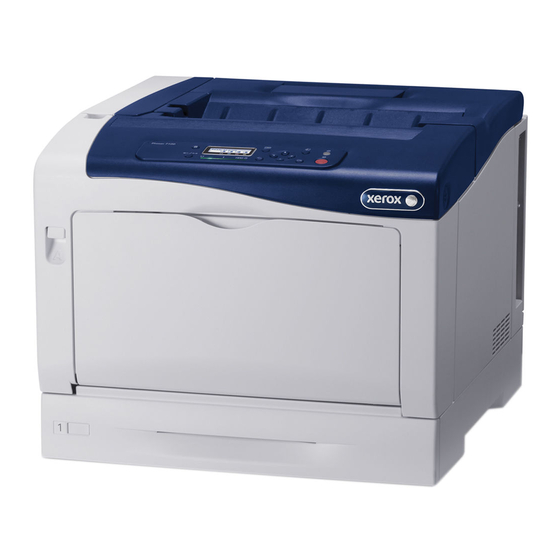
Page 44: Parts Of The Printer
General and Operation Overview Parts of the Printer Note: For additional tips, refer to the Doors and Covers video (also available in the Phaser 7100 Training materials). Front View s7100-154 Power Switch Cover A Cover A Release Latch Cover B Release Button... -
Page 45: Rear View
Toner Cartridges Transfer Roller (2nd BTR) Transfer Belt (IBT Unit) Toner Cartridge Cover ROS Assembly Cleaning Tool Cover C (Top Cover) Imaging Units Note: The Transfer Belt is not customer replaceable. Xerox Internal Use Only Phaser 7100 Service Manual 1-21... -
Page 46: Internal Components Under Cover B And The Waste Cartridge Cover
General and Operation Overview Internal Components Under Cover B and the Waste Cartridge Cover s7100-157 Cover B Release Button Fuser Unit Cover B Waste Cartridge Cover Duplex Unit Waste Cartridge 1-22 Phaser 7100 Service Manual Xerox Internal Use Only... -
Page 47: Printer Options
Printer Stand • External Wireless Network Adapter Additional Memory The Phaser 7100 features an additional slot that accepts a 512 MB or 1 GB of DDR2 DIMM. Memory module must meet the following characteristics: • PC2-5300 (667MHz memory bus speed) •... - Page 48 General and Operation Overview Productivity Kit (Hard Disk Drive) The Phaser 7100 printer supports an optional internal Hard Disk Drive. The Hard Disk Drive has a maximum 40 GB capacity. Features include: • Secure Print • Saved Print • Font Storage •...
- Page 49 The Optional 550-Sheet Feeder increases the input capacity of the printer and can be attached to the printer underneath Tray 1. Up to three Optional 550-Sheet Feeders can be installed on the Phaser 7100 printer.The Optional 550-Sheet Feeder is customer installable.
-
Page 50: Control Panel Layout
Comes On when the printer is online and Off when the printer is offline or has an error condition. It blinks while the printer is receiving data. Online Button Changes between the online and offline state. 1-26 Phaser 7100 Service Manual Xerox Internal Use Only... - Page 51 1. Press Down Arrow + OK simultaneously. 2. Press Down Arrow to find Reset Counter. Long Boot Diagnostics 1. Turn On the printer power while pressing Energy Saver + OK simultaneously. Xerox Internal Use Only Phaser 7100 Service Manual 1-27...
-
Page 52: Consumables
Each Toner Cartridge has a CRUM (Customer Replaceable Unit Meter) to record new or used cartridge and usage information. The CRUM contains a company ID, Region ID, and Xerox company name. A CRUM counts the amount of remaining toner. When toner empty is detected, Life End status will be sent to indicate toner empty. -
Page 53: Long Life Maintenance Items
A maintenance item is a printer part or assembly that has a limited life, and requires periodic replacement. Long Life Maintenance items are typically customer replaceable. The following listed items have limited life and require periodic replacement. Phaser 7100 Maintenance Items Item Description... -
Page 54: Consumables And Long Life Maintenance Display Messages
Replace the Fuser Unit Unable to print XXX_XXX *1 *1. XXX_XXX indicates the Error Code of the applicable parts (refer to HFSI Counter Chain-Link Number List page 2-21 in Chapter 2). 1-30 Phaser 7100 Service Manual Xerox Internal Use Only... -
Page 55: Specifications
• Color: As fast as 11 seconds Operating System • Windows: 2003 Server/ 2008 Server/ XP Pro/ XP/ Vista/ Windows 7 • Windows 8 (available post launch) Mac: OS 10.5 and later Linux: Redhat, SuSe, and Ubuntu. Xerox Internal Use Only Phaser 7100 Service Manual 1-31... -
Page 56: Memory Specifications
Max. Inrush Current - 100A, 10 msec or less when the power switch is turned On Power Consumption Low Power Printing Ready Energy Saver Sleep (Standby) Less than 600 W Less than 75 W Less than 55 W Less than 1 W 1-32 Phaser 7100 Service Manual Xerox Internal Use Only... -
Page 57: Environmental Specifications
Standard 600 dpi - 600 x 600 x 1 bit Enhanced 600 dpi - 1200 x 1200 x 1 bit (1/2 speed) Photo 1200 dpi - 600 x 600 x 8 bit Xerox Internal Use Only Phaser 7100 Service Manual 1-33... - Page 58 550-Sheet Tray Mode Tray 1 Tray 2/ 3/ 4 Speed Normal Mode Color Full Half 10.5 Full Half 10.5 * For Duplex mode calculations, front and back sides are considered separate pages. 1-34 Phaser 7100 Service Manual Xerox Internal Use Only...
-
Page 59: Paper And Tray Specifications
General and Operation Overview Paper and Tray Specifications The following tables list the recommended Xerox paper for the Phaser 7100 printer. Recommended media lists are also available on the Xerox web sites: • United States: www.xerox.com/paper • Europe: www.xerox.com/europaper Supported Paper Size... - Page 60 6.4 x 9 in. (162 x 229 mm) C6 Envelope 4.5 x 6.38 in. (114 x 162 mm) Note: Do not use envelopes with hot melt glue, windows, or metal clasps. 1-36 Phaser 7100 Service Manual Xerox Internal Use Only...
-
Page 61: Physical Dimensions And Clearances
11.5 in. (29.20 cm) Weight 28.6 lb. (13.0 kg) Optional 550-Sheet Feeder (unpackaged) Characteristic Width 19.6 in. (49.78 cm) Depth 23.4 in. (59.44 cm) Height 6.4 in. (16.26 cm) Weight 21.2 lb. (9.6 kg) Xerox Internal Use Only Phaser 7100 Service Manual 1-37... - Page 62 In order to function properly, the printer must be placed on a flat surface with the following minimum clearances. Standard Configuration 10 cm 3.9 in 76.2 cm 30.0 in 13 cm 5.1 in 10 cm 3.9 in 70 cm 145.4 cm 27.6 in 57.2 in s7100-164 1-38 Phaser 7100 Service Manual Xerox Internal Use Only...
- Page 63 Known problems that can occur as a result of exceeding the mounting surface specifications are: • Color-to-Color mis-registration, primarily in the horizontal direction. • A smear or line of toner approximately 40 mm from the trailing edge of the print. Xerox Internal Use Only Phaser 7100 Service Manual 1-39...
-
Page 64: Phaser 7100 Print Process
Phaser 7100 Print Process The Phaser 7100 utilizes a tandem system where each of the colors - Yellow, Magenta, Cyan, and Black (Y, M, C, K) has its own Imaging Unit and Developer. A toner image for each color is formed on the Imaging Unit and then transferred to the Intermediate Transfer Belt (Intermediate Transfer Unit). -
Page 65: Paper Path
Cleaning Blade : Laser Beam : Paper Feeding Detack Saw 2nd BTR (Transfer Roller) Laser Unit 1st BTR Erase Lamp Magnet Roller Cleaning Blade Bias Charge Roller (BCR) Cleaning Roller s7100-426 Xerox Internal Use Only Phaser 7100 Service Manual 1-41... -
Page 66: Waste Toner Collection
General and Operation Overview Waste Toner Collection The Phaser 7100 printer comes with separate systems for collecting waste toner at the Intermediate Transfer section, around each Imaging Unit, and depleted toner. There are two containers for waste toner in the Phaser 7100 printer. - Page 67 Waste Cartridge - Collects the waste toner that is generated during the cleaning of the Intermediate Transfer Belt. Figure 2 - Waste Toner Collection Path to the Waste Cartridge Waste Toner Motor Paddle (Waste Box) Paddle (Cleaner) Cleaning Blade Waste Box Full Sensor Waste Cartridge s7100-186 Xerox Internal Use Only Phaser 7100 Service Manual 1-43...
-
Page 68: Print Data Flow
ROS Assembly (Laser Beam) Electrostatic latent image on the Drum Toner image on the Drum (visible image) Toner image on the Intermediate Transfer Toner image on the paper Print image on the paper s7100-368 1-44 Phaser 7100 Service Manual Xerox Internal Use Only... - Page 69 Fast Scan Direction: number of dots/ inch • Slow Scan Direction: number of scan lines/ inch Number Of Dots / Inch Paper Feed Direction Number Of Scan Lines / Inch s7100-427 Xerox Internal Use Only Phaser 7100 Service Manual 1-45...
-
Page 70: Paper Transport
General and Operation Overview Paper Transport This section explains the paper transport paths in the Phaser 7100 printer, as well as the flow of paper movement through each of the transport section. Paper Feed Layout The paper transport layout and the parts related to paper transportation in a printer with a Duplex Unit and Tray 1 attached is shown in the following illustration. - Page 71 When the top level of the paper stack drops as paper is being fed, the Nudger Roller descends, the Lever releases the Gear, and the Bottom Plate Assembly rises. Nudger Roller Feed Roller Turn Roller Retard Roller Feed Roller Nudger Roller Retard Roller s7100-333 Xerox Internal Use Only Phaser 7100 Service Manual 1-47...
- Page 72 Spring rise along the trajectory of the Cam and lift up the Bypass Tray Bottom Plate Assembly. Bottom Plate Assembly Bypass Tray Assembly Bypass Tray Roller Assembly Retard Roller Assembly Bypass Tray Feed Gear Bypass Tray Feed Roller Assembly Bottom Plate Assembly Retard Roller Assembly s7100-170 1-48 Phaser 7100 Service Manual Xerox Internal Use Only...
- Page 73 Turn Roller. The Bypass Tray Turn Roller rotates by the drive from the Paper Handling Motor through the Turn Roller Clutch. Rubber Registration Roller Metal Registration Roller Bypass Tray Turn Roller s7100-428 Xerox Internal Use Only Phaser 7100 Service Manual 1-49...
- Page 74 Transfer Belt, or in front of the BTRs. The leading edge of the sheet reaches registration and is fed to the toner transfer section (Transfer Roller). Metal Registration Roller Rubber Registration Roller Registration Rollers Skewed Paper s7100-187 1-50 Phaser 7100 Service Manual Xerox Internal Use Only...
- Page 75 Fuser Motor and outputs the paper. The completion of paper output is detected by the Fuser Exit Sensor. Heat Roller Exit Roller Fuser Exit Sensor Heat Roller IBT Belt Assembly 2nd BTR (Transfer Roller) Pressure Belt s7100-188 Xerox Internal Use Only Phaser 7100 Service Manual 1-51...
- Page 76 Roller rotates in the duplex direction, it is being driven by the Duplex Motor. Also, the Duplex Motor drives the two Duplex Rollers to transport the paper to the Registration position. Duplex Motor Exit Roller Duplex Roller s7100-189 1-52 Phaser 7100 Service Manual Xerox Internal Use Only...
-
Page 77: Major Assemblies And Functions
Front Cover Interlock Switch Toner Cover Interlock Switch Front Cover Switch s7100-429 The Phaser 7100 printer contains the following Switches. • Toner Cover Interlock Switch - Detects if the Toner Cover is open. • Waste Cartridge Set Switch - Detects the installation of the Waste Cartridge. -
Page 78: Ros Assembly (Laser Unit) (Exposure)
MCU PWB. Note: The Laser Unit (ROS Assembly) is not a serviceable component. The Laser Unit can only be replaced as a whole assembly. DO NOT disassemble the Laser Unit. 1-54 Phaser 7100 Service Manual Xerox Internal Use Only... -
Page 79: Imaging Unit (Electric Charge/ Cleaning)
• Erase PWB - The Erase Lamp is used to discharge the Drum surface. One is allocated to each color (Yellow, Magenta, Cyan, and Black). Xerox Internal Use Only Phaser 7100 Service Manual 1-55... -
Page 80: Developer Housing Assembly (Development)
Magnet Roller - Contacts the Drum and forms toner images on the Drum. – Auger - Agitates the toner. – Trimmer - Evens out the layer of toner and carrier on the Magnet Roller. 1-56 Phaser 7100 Service Manual Xerox Internal Use Only... - Page 81 General and Operation Overview Toner Supply The Phaser 7100 uses dry bi-component magnetic toner with the two components: Toner and Carrier. Other than toner, a small amount of carrier is also present in the Toner Cartridge. To prevent the degradation of the toner, the toner together with the carrier are supplied into the Developer Housing Assembly while at the same time removing the used toner from the Developer Housing Assembly.
-
Page 82: Intermediate Transfer Belt (Transfer/ Cleaning)
Waste Cartridge Full Sensor (Toner Full Sensor) - Detects whether the Waste Cartridge is full with • waste toner. • Waste Toner Motor (IBT Cleaner Motor Assembly) - Drives the Paddle for transporting the waste toner. 1-58 Phaser 7100 Service Manual Xerox Internal Use Only... - Page 83 2nd BTR (Transfer Roller) - Contacts the paper at the opposite side of the toner transfer surface and transfers the toner image that was formed on the Intermediate Transfer Belt surface onto the paper. Xerox Internal Use Only Phaser 7100 Service Manual 1-59...
-
Page 84: Fuser Assembly (Fusing/ Paper Output)
Main Heater Lamp - A Lamp located inside the Heat Roller that heats the left and right ends of • the Heat Roller. 1-60 Phaser 7100 Service Manual Xerox Internal Use Only... - Page 85 Fuser PWB - Detects whether the Fuser had ever been installed before when the Fuser Assembly is • used for the first time. • Fuser Exit Sensor - Detects that paper has passed through the Fuser Assembly section. (No paper: Sensor blocked) Xerox Internal Use Only Phaser 7100 Service Manual 1-61...
-
Page 86: Tray 1 Paper Feeder
Tray 1 No Paper Sensor - Detects whether paper exists in the paper tray by changes in the Actuator. (No paper: Sensor blocked) • Feed Roller Clutch - Transfers the drive of the Paper Handling Motor to the Feed Roller Assembly. 1-62 Phaser 7100 Service Manual Xerox Internal Use Only... -
Page 87: Bypass Tray
Bypass Tray Feed Solenoid - Transfers the drive of the Paper Handling Motor to the Bypass Tray Feed Roller Assembly. Bypass Tray No Paper Sensor - Detects whether or not paper exists on the Bypass Tray by • changes in the Actuator. (No paper: Sensor blocked) Xerox Internal Use Only Phaser 7100 Service Manual 1-63... -
Page 88: Registration
Bypass Tray Turn Roller. • Registration Clutch - Transfers the drive of the Paper Handling Motor to the Rubber Registration Roller and Metal Registration Roller that are part of the Registration Chute Assembly. 1-64 Phaser 7100 Service Manual Xerox Internal Use Only... -
Page 89: Drive
Paper Handling Motor (Paper Handling Drive Assembly) - A DC Motor that drives the Bypass Tray, Tray 1, and the Rollers in the Registration section. • Fuser Motor (Fuser Drive Assembly) - A DC Motor that drives the Heat Roller in the Fuser Assembly. Xerox Internal Use Only Phaser 7100 Service Manual 1-65... - Page 90 (Y) Imaging Unit Components – Drum (Y) – Auger Gear 1 – Auger Gear 2 – Auger Assembly Note: The Imaging Unit (M/ C) are also made up of the similar components. 1-66 Phaser 7100 Service Manual Xerox Internal Use Only...
- Page 91 – Auger Gear 2 – Trickle Gear 1 – Trickle Gear 2 – Trickle Gear 3 – Trickle Gear 4 – Auger Assembly – Trickle Auger 1 – Trickle Auger 2 Xerox Internal Use Only Phaser 7100 Service Manual 1-67...
- Page 92 Input Gear Supply Auger Gear Idle Drive Gear 3 Idle Drive Gear 2 D1 Drive Gear Developer Motor (K) s7100-174 Note: This is similar for the Developer Housing Assembly (Y/ M/ C). 1-68 Phaser 7100 Service Manual Xerox Internal Use Only...
- Page 93 Oneway Nudger Clutch Feed Roller s7100-328 • Paper Handling Drive Assembly Components – Paper Handling Motor – Paper Handling Pinion Gear – F1 E Gear – F2 E Gear – F3 E Gear Xerox Internal Use Only Phaser 7100 Service Manual 1-69...
- Page 94 Metal Registration Gear – Metal Registration Roller • Right Turn Bracket Assembly Components – R1 Idler Gear – R2 Idler Gear • Nudger Support Assembly Components – Nudger Idle Gear – Nudger Gear 1-70 Phaser 7100 Service Manual Xerox Internal Use Only...
- Page 95 Fuser Assembly Components – Input Gear – Heat Roller Gear – Exit 1 Idler Gear – Clutch Assembly Gear – Exit 2 Idler Gear – Exit Gear – Exit Roller – Heat Roller Xerox Internal Use Only Phaser 7100 Service Manual 1-71...
-
Page 96: Fans And Temp/ Humidity Sensor
Temp/ Humidity (Environmental) Sensor - Detects the temperature and humidity in the printer. The detected temperature/ humidity is used as the condition to perform the various voltage correction during Process Control. 1-72 Phaser 7100 Service Manual Xerox Internal Use Only... -
Page 97: Electrical
EEPROM PWB - This is a non-volatile memory that stores the printer data. • Developer PWB - Supplies power to the Developer Motor. • Front Cover Switch (Interlock Cap Switch) - Monitors the Open/ Close state of the Front Cover. • Xerox Internal Use Only Phaser 7100 Service Manual 1-73... - Page 98 PWB to the new I/P PWB or the old MCU PWB to the new MCU PWB. MCU PWB NVRAM The MCU PWB NVRAM stores information such as serial number and print volume. Figure 1 - NVRAM on MCU PWB NVRAM s7100-369 1-74 Phaser 7100 Service Manual Xerox Internal Use Only...
- Page 99 Image Processor PWB NVRAM The Image Processor PWB NVRAM stores information such as printer settings, network settings, print language settings, and parameters information. Figure 2 - NVRAM on Image Processor PWB NVRAM s7100-370 Xerox Internal Use Only Phaser 7100 Service Manual 1-75...
-
Page 100: Duplex Feed (Option)
Duplex Jam Sensor - Detects whether the paper is being transported in the Duplex Assembly by • changes in the Actuator. (No paper: Sensor blocked) • Duplex PWB - Controls the various components in the Duplex Assembly. 1-76 Phaser 7100 Service Manual Xerox Internal Use Only... - Page 101 Duplex In Clutch s7100-200 • Fuser Unit Components – Duplex Idler Gear 1 – Delay Assembly Gear – Clutch Assembly Gear – Exit 2 Idler Gear – Exit Gear – Exit Roller Xerox Internal Use Only Phaser 7100 Service Manual 1-77...
-
Page 102: 550-Sheet Feeder (Option)
Sensor is located near the Turn Roller Assembly. • Feeder Motor (Option Drive Assembly) - A DC Motor that drives the 550-Sheet Feeder Rollers. • Feeder PWB - Controls all the 550-Sheet Feeder components. 1-78 Phaser 7100 Service Manual Xerox Internal Use Only... - Page 103 Feed Motor s7100-331 • Option Drive Assembly Components – Feeder Motor – Idler Gear 21-119 – Idler Gear 57 • Nudger Support Assembly Components – Nudger Idler Gear – Nudger Gear Xerox Internal Use Only Phaser 7100 Service Manual 1-79...
-
Page 104: Operation Mode
General and Operation Overview Operation Mode The following 4 modes are available in the Phaser 7100 printer: Running Mode, Ready Mode, Low Power Mode, and Sleep Mode. Running Mode Running Mode contains operating states such as data receive/ image creation, or recording (print). -
Page 105: Engine Status
X<Y = Low Power Sleep at (Y-X) Minutes Event X Minutes Low Power Ready Sleep Mode Mode Mode Y Minutes Job End Job Start Job Start Job Start Running Mode s7100-430 Xerox Internal Use Only Phaser 7100 Service Manual 1-81... -
Page 106: Job Control And Functions
End Guide Left Side Guide s7100-332 Sector Gear Paper Size Switch State and Paper Size Paper Size Switch Paper Size A5 LEF B5 LEF A4 LEF Letter LEF Letter SEF A4 SEF 1-82 Phaser 7100 Service Manual Xerox Internal Use Only... -
Page 107: Cancel Job
System Memory Option, even a 1200 dpi, A3, Duplex, and color document with the worst compression rate (256MB for page data only) can be printed uncompressed. Printing is always possible in this mode. Xerox Internal Use Only Phaser 7100 Service Manual 1-83... -
Page 108: Job Spool
Delayed Print allows user to set a time to start the print job. A print job can be delayed up to 24 hours from the original job submission time. The Delayed Print default time is midnight. 1-84 Phaser 7100 Service Manual Xerox Internal Use Only... -
Page 109: E-Mail Print
The instances where this half speed has occurred are recorded in the Shutdown Report (Information Pages, Troubleshooting Pages, and Print Test Patterns, Reports on page 1-90). Xerox Internal Use Only Phaser 7100 Service Manual 1-85... -
Page 110: Process Control
The timings at which the Potential Control Corrections perform are: at power On, at the completion of a print job, in the middle of a print job under certain circumstances. 1-86 Phaser 7100 Service Manual Xerox Internal Use Only... - Page 111 This mode is to solve that problem. It counts the number of pixels as printing is in progress and pauses printing when it has reached the specified value or lower to remove excess toner from the Developer Housing Assembly. Xerox Internal Use Only Phaser 7100 Service Manual 1-87...
-
Page 112: Color Registration Control
General and Operation Overview Color Registration Control The Phaser 7100 is a full color printer that uses the tandem system, where each color (Yellow, Magenta, Cyan, and Black) has its own Drum and Developer Housing Assembly. Because each color forms an image on their own Drum, which are then overlaid to create one image, color shift may occur due to Drum misalignments, skewed installation positions, etc. - Page 113 General and Operation Overview Open Loop Regi Con The Color Shift for each color is predicted and corrected based on the changes in the printer internal temperature when detected by the Temperature Sensor. Xerox Internal Use Only Phaser 7100 Service Manual 1-89...
-
Page 114: Information Pages, Troubleshooting Pages, And Print Test Patterns, Reports
General and Operation Overview Information Pages, Troubleshooting Pages, and Print Test Patterns, Reports The following Embedded Pages and Reports are available in the Phaser 7100 printer. The pages can be accessed through the Control Panel at various locations. Page Description... - Page 115 Contains the list for number of times the various types of paper jams that had occurred. HFSI Report Contains the list for the usage status of the various Long Life Maintenance Items. Xerox Internal Use Only Phaser 7100 Service Manual 1-91...
- Page 116 General and Operation Overview 1-92 Phaser 7100 Service Manual Xerox Internal Use Only...
- Page 117 Media Jam and Paper Path Troubleshooting • Clutch Troubleshooting • Motor Troubleshooting • Sensor Troubleshooting • Solenoid Troubleshooting • Switch Troubleshooting • Sheet Feeder Troubleshooting • Electrical Troubleshooting • Network Troubleshooting • Operating System and Application Problems Xerox Internal Use Only Phaser 7100 Service Manual...
-
Page 118: Introduction
10. Inspect the interior of the printer for damaged wires, loose connections, toner leakage, and damaged or obviously worn parts. 11. If the Toner Cartridge is damaged, replace with new one. Phaser 7100 Service Manual Xerox Internal Use Only... -
Page 119: Control Panel Shortcut
Reset Counter 1. Press Down Arrow + OK simultaneously. 2. Press Down Arrow to find Reset Counter. Long Boot Diagnostics 1. Turn On the printer power while pressing Energy Saver + OK simultaneously. Xerox Internal Use Only Phaser 7100 Service Manual... -
Page 120: Phaser 7100 Printer Menu (Customer Support Engineer)
Error Troubleshooting Phaser 7100 Printer Menu (Customer Support Engineer) Additional hidden reports and features are available ONLY in the Printer Control Panel Menu. Accessing the Customer Support Engineer Printer Menu: Press Up Arrow 3 times. Press Menu. Menu List Secure Jobs and Saved Jobs. -
Page 121: Diagnostic Test
(REP 12.19 Memory (Optional) page 4-234). 3. Replace the I/P PWB RAM DIMM #2 (REP 12.19 Memory (Optional) page 4-234). 4. Replace the I/P PWB (REP 12.17 Image Processor (I/P) PWB page 4-228). Xerox Internal Use Only Phaser 7100 Service Manual... - Page 122 4-228). OS Management Area Test Font ROM Test Option Font Pass Replace the I/P PWB (REP 12.17 Image Processor Fail Option Font ROM (I/P) PWB on page 4-228). Skip Checksum Test Phaser 7100 Service Manual Xerox Internal Use Only...
- Page 123 File System Pass Format the HDD. Fail From the Control Panel, HDD File Check press the Energy Saver + Skip Up Arrow + Down Arrow buttons, and check if it can recover. Xerox Internal Use Only Phaser 7100 Service Manual...
- Page 124 1. Disconnect and Communication Test 2 reconnect the P304 Fail connector of the MCU IOT and Data Link Cable. Layer Communication 2. Replace the MCU PWB Test (REP 12.4 MCU PWB page 4-206). Phaser 7100 Service Manual Xerox Internal Use Only...
-
Page 125: System Booting
Controller by force and starts up. HDD Forced Energy Saver + -- BOOT MODE -- Formats the HDD by force. This Formatting Down + Up operation resets the HDD to partitions HDD Format Mode at factory settings. Xerox Internal Use Only Phaser 7100 Service Manual... - Page 126 Long Boot Diag Energy Saver + -- BOOT MODE -- Performs a more detailed check than the Start Up usual device diagnostic items at the LongDiag Mode start up of the printer. 2-10 Phaser 7100 Service Manual Xerox Internal Use Only...
-
Page 127: Long Boot Diagnostic
Back Plane Connection Detects the connection with the Back Plane 016-327 Detection MCU Connection Detection Detects the connection with the IOT 016-328 Font ROM Test Standard Font ROM checksum test 116-380 Xerox Internal Use Only Phaser 7100 Service Manual 2-11... - Page 128 USB 2.0 Device Test USB 2.0 Target device test 016-365 HDD Test HDD device test 016-366 UFS test 016-367~382 UI Test UI device test 016-362 Standard ROM Write Mode Test QRY test 016-336 2-12 Phaser 7100 Service Manual Xerox Internal Use Only...
-
Page 129: Jam Zone
Error Troubleshooting Jam Zone The following diagram illustrates the jam areas of the Phaser 7100 printer. Fuser Exit Sensor [Fuser Assembly] Cover A Lever E Duplex Jam Sensor Cover B Bypass Tray No Paper Sensor Bypass Tray Registration Sensor Tray1... -
Page 130: Service Diagnostics
Error Troubleshooting Service Diagnostics The Phaser 7100 printer has built-in diagnostics to test electromechanical components, display status, and provide some NVRAM access. Use these tests to diagnose problems and isolate which component or sub assembly part needs replacement. If confronted with an error that requires more than a cursory investigation to clear or when directed by a troubleshooting procedure, use Service Diagnostics to exercise selected sub-assemblies of parts in the vicinity of the reported error. -
Page 131: Service Diagnostics Menu Map
DC949 ATC Init Set No Function DC950 ATC Setup No Function DC991 Tone Up Down ATC Read No Function (*) Available only when HDD installed (**) Available only when error 124-315 occurs s7100-462 Xerox Internal Use Only Phaser 7100 Service Manual 2-15... -
Page 132: Service Diagnostics Routines
Billing Counter Value among the PWB (available only when when MCU PWB or I/P PWB is replaced, error 124-315 occurs) set those values stored in the non- replaced PWB to the replaced PWB. 2-16 Phaser 7100 Service Manual Xerox Internal Use Only... - Page 133 The Max Setup adjustment items cannot be run. DC924 Adjust TRC No Function DC937 Pcon Print No Function DC949 ATC Init Set No Function DC950 ATC Setup No Function DC991 Tone Up Down No Function Xerox Internal Use Only Phaser 7100 Service Manual 2-17...
-
Page 134: Preventive Diag
Press Right Arrow to display the history information (Chain-Link No., Total DV, Date, Time). Note: For previous error history, press Down Arrow to display the error information. Press Menu to return to the Diagnostics Preventive Diag menu. 2-18 Phaser 7100 Service Manual Xerox Internal Use Only... - Page 135 If it is applicable, the current counter value appears. – If the input Chain-Link Number is not applicable, the screen appears. In this case, return to the Chain-Link Number input screen. Xerox Internal Use Only Phaser 7100 Service Manual 2-19...
- Page 136 If the input Chain-Link Number is not applicable, the screen appears. In this case, return to the Chain-Link Number input screen. 10. Press Menu to return to the Diagnostics Preventive Diag screen. 2-20 Phaser 7100 Service Manual Xerox Internal Use Only...
- Page 137 It is it is recommended to Colors) replace the Dispense Motor, • Registration Roller Registration Roller, and Trickle • Trickle Motor Motor, and reset the life counter when use the engine past the rated life. Xerox Internal Use Only Phaser 7100 Service Manual 2-21...
- Page 138 L ≤ 216 mm (8.5 inch)*4 +4 e. L ≤ 216 mm (8.5 inch)*5 +5 (900 mm Long Paper) f. 216 mm (8.5 inch)*5 < L +6 (1200 mm Long Paper) 2-22 Phaser 7100 Service Manual Xerox Internal Use Only...
-
Page 139: Fault Diag
If the Chain-Link Number is not applicable, the NG screen appears. When 8 of the components have been registered, the Max Over. Delete? - Press OK deletion confirmation screen appears. Press OK to complete the registration. Xerox Internal Use Only Phaser 7100 Service Manual 2-23... - Page 140 When the Delete All - Press OK to run screen is displayed again, the process has been completed. Press Menu to return to the Diagnostics - Fault Diag. screen. 2-24 Phaser 7100 Service Manual Xerox Internal Use Only...
- Page 141 The detected temperature at the Thermo Sensor that is part of the CTD Sensor Assembly. Environment Sensor Humidity The detected humidity at the Humidity Sensor. Environment Sensor Temperature The detected temperature at the Humidity Sensor. Xerox Internal Use Only Phaser 7100 Service Manual 2-25...
- Page 142 8 components) can be registered by repeating steps 6 and 7. If the Chain-Link Number is not applicable, the screen appears. Press OK to return to the Chain-Link Number input screen. 2-26 Phaser 7100 Service Manual Xerox Internal Use Only...
- Page 143 When two or more components are registered, use Down/ Up Arrow to select the applicable component and press OK. Note: Even after the tests are stopped individually, the Chain-Link Number will remain in the list screen. Xerox Internal Use Only Phaser 7100 Service Manual 2-27...
- Page 144 Sensor (PL 2.2.2) (Tray1) Registration Sensor Detects the High/ Low states of the Registration Sensor (PL 5.1.3) Fuser Exit Sensor Detects the High/ Low states of the Fuser Exit Sensor (Fuser Unit) (PL 10.1.1) 2-28 Phaser 7100 Service Manual Xerox Internal Use Only...
- Page 145 Detects the High/ Low states of the No Paper Sensor (PL 15.2.8) (Tray 2) Option Feeder 2 No Paper Sensor Detects the High/ Low states of the No Paper Sensor (PL 15.2.8) (Tray 3) Xerox Internal Use Only Phaser 7100 Service Manual 2-29...
- Page 146 Waste Toner Cartridge Full Sensor Detects the High/ Low states of the Waste Cartridge Full Sensor (PL 9.1.5) Belt Retract Sensor Detects the High/ Low states of the Belt Retract Sensor (CAM Assembly) (PL 9.1.8) 2-30 Phaser 7100 Service Manual Xerox Internal Use Only...
- Page 147 Even with the IBT Unit removed, Motor (1/2) C) (Drive Assembly) (PL 11.1.2) rotating the Drum (Y/ M/ C) this (1/2 Speed: Forward Rotation) way for too long could cause the blade to curl up. Xerox Internal Use Only Phaser 7100 Service Manual 2-31...
- Page 148 Solenoid (PL 4.3.10) Feed Clutch Turns On the Feed Roller Clutch (PL 2.2.8) Turn Clutch Turns On the Turn Roller Clutch (PL 5.1.9) Duplex Unit Clutch Turns On the Duplex Clutch (PL 14.2.20) 2-32 Phaser 7100 Service Manual Xerox Internal Use Only...
- Page 149 (PL 15.2.25) (Tray 2) Option Feeder 2 Turns On the Turn Roller Clutch Turn Clutch (PL 15.2.25) (Tray 3) Option Feeder 3 Turns On the Turn Roller Clutch Turn Clutch (PL 15.2.25) (Tray 4) Xerox Internal Use Only Phaser 7100 Service Manual 2-33...
- Page 150 Imaging Unit (071-001) first. (Normal Speed) Attempting to rotate the Developer Motor without rotating the Imaging Unit first could cause damage to the Drum and risk internal printer contamination due to toner. 2-34 Phaser 7100 Service Manual Xerox Internal Use Only...
- Page 151 Imaging Unit (071-002) first. (1/2 Speed) Attempting to rotate the Developer Motor without rotating the Imaging Unit first could cause damage to the Drum and risk internal printer contamination due to toner. Xerox Internal Use Only Phaser 7100 Service Manual 2-35...
- Page 152 As rotating this way for too long will cause contamination in the printer and background appearing on the paper due to toner cloud; perform the check only in short time periods. 2-36 Phaser 7100 Service Manual Xerox Internal Use Only...
- Page 153 Although there is no limitation for this, it is not possible to switch (Cam Assembly) (PL 9.1.8) between Color and B/W modes as this will not stop automatically. Belt Color Mode Belt Monochrome Mode Xerox Internal Use Only Phaser 7100 Service Manual 2-37...
- Page 154 To set up the individual Partition, go to step 8. Press Down Arrow to display the Setup - Press OK to run screen at the same level. Go to step 11. 2-38 Phaser 7100 Service Manual Xerox Internal Use Only...
- Page 155 12. Press OK to run the setup. As the process is running, the Setup - In progress screen is displayed. When the process has completed successfully, the Setup - Completed screen is displayed. Xerox Internal Use Only Phaser 7100 Service Manual 2-39...
- Page 156 Press OK to run the fault prediction. As the process is running, the Predict Fault - In progress screen is displayed. When the process has completed successfully, the Predict Fault - Completed screen is displayed. 2-40 Phaser 7100 Service Manual Xerox Internal Use Only...
- Page 157 Error Troubleshooting When the process has completed with error, the Predict Fault - Completed-Error screen is displayed. Press Menu to return to the Diagnostics - Fault Diag. screen. Xerox Internal Use Only Phaser 7100 Service Manual 2-41...
- Page 158 The DC612 Print Pattern routine allows user to print the test patterns that were output from the built-in pattern generator. The Phaser 7100 printer contains seven test patterns that can be printed from the Control Panel. Print Test Patterns Note: Test pattern numbers 1 - 16 are not available in the Phaser 7100 printer.
- Page 159 12. Press Right Arrow to display the tray selection screen. To select a Tray, press Down/ Up. Note: There are 5 selectable Trays: Tray 1, Tray 2, Tray 3, Tray 4, and (SMH) Bypass Tray. Tray 1 is set as the default. Xerox Internal Use Only Phaser 7100 Service Manual 2-43...
- Page 160 16. After the process has completed, the DC612 PatternPrt - Press OK to run screen will be displayed again. 17. Press Menu to return to the Diagnostics - Fault Diag. screen. 2-44 Phaser 7100 Service Manual Xerox Internal Use Only...
-
Page 161: Adjustment
If the Chain-Link No. is not applicable, the NG screen will be displayed. Press OK to return to the Chain-Link No. input screen. To change the current NVM value, use Left/ Right to move the cursor and Down/ Up Arrow to change the number. Xerox Internal Use Only Phaser 7100 Service Manual 2-45... - Page 162 If the changed value is incorrect, the Value NG screen appears. Press OK to return to the Chain- Link No. input screen. Press Menu to return to the Diagnostics - Adjustment menu screen. 2-46 Phaser 7100 Service Manual Xerox Internal Use Only...
- Page 163 Meter Black values will be displayed in sequence for SYS1, SYS2 and IOT. Note: The Serial No. and Product No. of a new PWB is always be displayed with an “ ”. Xerox Internal Use Only Phaser 7100 Service Manual 2-47...
- Page 164 10. Press OK to confirm the Serial No. If the Serial No. is correct, the re-entry screen is displayed for reconfirmation. Note: Use Left/ Right Arrow to move the cursor and Down/ Up Arrow to change the number. 2-48 Phaser 7100 Service Manual Xerox Internal Use Only...
- Page 165 If the Serial No. is incorrect, the DC132 Set Serial - Serial Number NG screen appears. Press OK to return to the input screen. 12. Press Menu to return to the Diagnostics - Adjustment menu screen. Xerox Internal Use Only Phaser 7100 Service Manual 2-49...
- Page 166 The functions of the menus described here have great effect on the print quality and operation of the printer. Therefore, do not change the settings unless specified otherwise in this manual. Use the NVM Initialization procedure as a last option when servicing the Phaser 7100. Notes: •...
- Page 167 ” appears on the right side of the display. 11. Use Right Arrow or Menu to display the NVM Initialized - Please exit Diag screen. 12. Press Menu to return to the Diagnostics - Adjustment menu screen. Xerox Internal Use Only Phaser 7100 Service Manual 2-51...
-
Page 168: Sub System Check
DC676 Adjust ROS - Completed screen is displayed. If the process has completed with error, the DC676 Adjust ROS - Completed-Error screen is displayed. Press Menu to return to the Diagnostics - Adjustment menu screen. 2-52 Phaser 7100 Service Manual Xerox Internal Use Only... -
Page 169: Messages, Chain Link Codes, And Procedures
Machine Control Unit Non-volatile Random Memory. Used instead of NVRAM. NVRAM Non-volatile Random Access Memory Random Access Memory Registration Read Only Memory VOUT Output voltage from ADC Sensor Xero Imaging Unit Drum Drive Xerox Internal Use Only Phaser 7100 Service Manual 2-53... -
Page 170: Error Messages And Chain-Link Codes
010-346 Fuser Main Lamp Data Renewal Fail 2-83 010-347 Fuser Sub Lamp Data Renewal Fail 2-83 010-355 Fuser Cool Down Timeout Fail 2-83 010-420 Fusing Unit Assembly Change Soon (ERU) ----- 2-54 Phaser 7100 Service Manual Xerox Internal Use Only... - Page 171 802.1x Authentication Client Certificate Setting Error 2-97 016-450 SMB Host Name Duplicated 2-98 016-453 Dynamic DNS - IPv6 Address Dynamic Update Failed (DMP2007) 2-98 016-454 Dynamic DNS - IPv4 Address Dynamic Update Failed 2-98 Xerox Internal Use Only Phaser 7100 Service Manual 2-55...
- Page 172 Remote Download File Write to HDD Error 2-110 016-543 Authentication Agent Error *REALM_UNKNOWN 2-111 016-545 Authentication Agent Error *CLOCKSKEW_ERR 2-111 016-556 Authentication Agent Error *SERVICE_IS_PROCESSING 2-112 016-557 Authentication Agent Error *INTERNAL_ERROR 2-112 2-56 Phaser 7100 Service Manual Xerox Internal Use Only...
- Page 173 016-709 PLW Command Error Detected By PLW Decomposer 2-126 016-710 Delayed Print Fail 2-126 016-716 Invalid TIFF File. The files to be spooled in TIFF has exceeded the disk 2-127 capacity. Xerox Internal Use Only Phaser 7100 Service Manual 2-57...
- Page 174 2-139 016-747 Insufficient memory when drawing an annotation image 2-139 016-748 Full Status detected at folder access and job is canceled 2-140 016-749 PJL/ XPJL Detected an Unprintable Print Language 2-140 2-58 Phaser 7100 Service Manual Xerox Internal Use Only...
- Page 175 2-153 016-793 MF I/O. HDD Full 2-154 016-798 No Trust Marking Option 2-154 016-799 Print Instruction Combination (Stored File Size, Paper Size, Paper Tray, 2-155 Duplex Settings, and Output Tray) Error Xerox Internal Use Only Phaser 7100 Service Manual 2-59...
- Page 176 Recall Status Mismatch (EP System) 2-168 021-511 Installation Status Mismatch (EP System) 2-168 021-512 EP-SV Installation Conflict (EP System) 2-169 021-513 EP-DX Installation Conflict (EP System) 2-169 021-514 TRESS Installation Conflict (EP System) 2-169 2-60 Phaser 7100 Service Manual Xerox Internal Use Only...
- Page 177 021-943 EP Accessory - Print Service Paused By Disable 2-177 021-944 EP Accessory - Print Service Paused By Color Mode Restriction 2-178 021-945 EP Accessory - Service Paused By Disable 2-177 Xerox Internal Use Only Phaser 7100 Service Manual 2-61...
- Page 178 Image Output. PCI Bus Error 2-184 024-370 Marker Code Detection Error 2-185 024-371 The communication between the ESS and IOT has not been established, 2-186 which is detected by the Controller. 2-62 Phaser 7100 Service Manual Xerox Internal Use Only...
- Page 179 Size Mismatch Tray 3: Measured Length Mismatch 2-193 024-913 Size Mismatch Tray 4: Measured Length Mismatch 2-193 024-923 Operation Y Toner Empty 2-195 024-924 Operation M Toner Empty 2-195 024-925 Operation C Toner Empty 2-195 Xerox Internal Use Only Phaser 7100 Service Manual 2-63...
- Page 180 An error occurred when HDD initialization of Diagnostics was executed 2-207 026-704 XDW Error 2-208 026-705 XDW Short of Memory 2-208 026-706 XDW Print Prohibited 2-209 026-707 XDW Unlock Failed 2-209 2-64 Phaser 7100 Service Manual Xerox Internal Use Only...
- Page 181 Link to Application During Web Service Interface - Server Not Found 2-222 027-721 Link to Application During Web Service Interface - Destination Not Found 2-222 027-722 Link to Application During Web Service Interface - Connection Timeout 2-223 Xerox Internal Use Only Phaser 7100 Service Manual 2-65...
- Page 182 042-335 Developer Fan (Process Fan 1) Failure 2-238 042-347 Drum YMC Motor Drive Fail 2-239 042-348 Over Temperature Detect ----- 042-398 LVPS Fan Failure 2-241 042-610 Speed Limit Status Detected ----- 2-66 Phaser 7100 Service Manual Xerox Internal Use Only...
- Page 183 Tray 4 Miss Feed Jam 2-260 074-310 Tray 4 Motor Fail 2-262 074-311 Tray 4 Mode Fail 2-263 075-100 Bypass Tray Miss Feed Jam 2-264 077-101 Registration Sensor Off Jam (Too Long) 2-266 Xerox Internal Use Only Phaser 7100 Service Manual 2-67...
- Page 184 Imaging Unit Y CRUM Trouble Info 2-281 091-421 Imaging Unit M Near Life End ----- 091-426 Imaging Unit M Pre Near Life End ----- 091-427 Imaging Unit M CRUM Trouble Info 2-282 2-68 Phaser 7100 Service Manual Xerox Internal Use Only...
- Page 185 Imaging Unit Y End Of Life 2-284 091-933 Imaging Unit M End Of Life 2-284 091-934 Imaging Unit C End Of Life 2-284 092-316 Environment Sensor Fail 2-298 092-317 Temperature Sensor Fail 2-300 Xerox Internal Use Only Phaser 7100 Service Manual 2-69...
- Page 186 Toner M CRUM Trouble Info 2-308 093-429 Toner C CRUM Trouble Info 2-308 093-912 Toner K Empty 2-309 093-913 Toner CRUM Not Position Y 2-310 093-914 Toner CRUM Not Position M 2-310 2-70 Phaser 7100 Service Manual Xerox Internal Use Only...
- Page 187 094-420 IBT Unit End Warning 2-315 094-422 2nd BTR Unit End Warning (Quality Life End) 2-318 102-356 EWS-related Fatal Error 2-319 116-220 Downloader Initialization Failure during Transition to Download Mode 2-320 Xerox Internal Use Only Phaser 7100 Service Manual 2-71...
- Page 188 Various fatal errors detected by the redirector. 2-338 116-349 An error occurred when calling the Pflite function using the SIF. 2-338 116-351 An EtherTalk-related fatal error. 2-338 116-353 HDD Physical Fail 2-339 2-72 Phaser 7100 Service Manual Xerox Internal Use Only...
- Page 189 DCS Fatal Error 2-347 116-385 IDC Software Fail 2-347 116-387 MRC HW Fatal Error 2-350 116-388 The necessary HD was not installed. 2-351 116-389 The necessary additional RAM was not installed. 2-352 Xerox Internal Use Only Phaser 7100 Service Manual 2-73...
- Page 190 116-739 The form/ logo data cannot be registered due to insufficient RAM or Hard 2-365 Disk space. 116-740 Value Calculation Error. The value calculated in the Interpreter exceeded 2-366 the limit. 2-74 Phaser 7100 Service Manual Xerox Internal Use Only...
- Page 191 At least one of the Product a/f Model at the 3 locations is different. All 2-375 Product Model mismatch. 124-318 The Product Type for SWKey was not set at all 3 locations. Product Type for 2-376 SWKey fails. Xerox Internal Use Only Phaser 7100 Service Manual 2-75...
- Page 192 124-353 One of CRUM OEM destinations is different from the others (SYS 2). 2-390 124-360 All three CRUM Enable/ Disable settings are not set (0 or different values 2-397 are set). 2-76 Phaser 7100 Service Manual Xerox Internal Use Only...
- Page 193 127-354 FTP Server Fatal Error 2-404 127-396 Mail I/O-related Fatal Error 2-404 127-398 IPP-related Fatal Error 2-404 127-399 JME-related Fatal Error 2-404 202-399 Timer Internal Error Detected by UI Cont 2-405 Xerox Internal Use Only Phaser 7100 Service Manual 2-77...
-
Page 194: Fuser Unit Exit Sensor Jam
Check the installation of the Registration Roller Go to step 3. Reinstall the (Registration Chute) (REP 5.1 Registration Chute Registration Chute. Assembly on page 4-114). Is the Registration Chute installed properly? 2-78 Phaser 7100 Service Manual Xerox Internal Use Only... - Page 195 Fuser Motor (REP 12.4 MCU PWB page 2-433. Perform DC330 Component Control on page 4-206). page 2-26 [010-001] to check the operation of the Fuser Motor. Is the Fuser Motor operating properly? Xerox Internal Use Only Phaser 7100 Service Manual 2-79...
-
Page 196: Exit Off Jam
Fuser Motor (REP 12.4 MCU PWB page 2-433. Perform DC330 Component Control on page 4-206). page 2-26 [010-001] to check the operation of the Fuser Motor. Is the Fuser Motor operating properly? 2-80 Phaser 7100 Service Manual Xerox Internal Use Only... -
Page 197: Fuser Motor Fail
MCU PWB, as well as between the Fuser connectors P/J475, Motor and LVPS PWB. P/J4751, P/J4755, Are the connectors P/J475, P/J4751, P/J4755, P/J524, P/J2711, P/J524, P/J2711, and P/J242 connected and P/J242. securely? Xerox Internal Use Only Phaser 7100 Service Manual 2-81... - Page 198 4.7 Fuser Drive on page 4-211). Measure the voltage between the LVPS PWB Assembly GND <=> P/J524-1. page 4-99). Is there a voltage (approx. +24VDC) output? Close the Interlock Switch and check. 2-82 Phaser 7100 Service Manual Xerox Internal Use Only...
-
Page 199: Fuser Unit Fail
• 010-345: Fuser Unit Hard Relay Off Fail • 010-346: Fuser Main Lamp Data Renewal Fail • 010-347: Fuser Sub Lamp Data Renewal Fail • 010-355: Fuser Cool Down Timeout Fail Xerox Internal Use Only Phaser 7100 Service Manual 2-83... - Page 200 P/J601 <=> P/J503 conducting page 4-80). properly? Check the conductivity of the Option Harness Go to step 6. Replace the Option Assembly. Harness Assembly. Is the connection between P/J505 <=> P/J464 conducting properly? 2-84 Phaser 7100 Service Manual Xerox Internal Use Only...
- Page 201 Does the error persist? Replace the AC PWB (REP 12.5 AC PWB Replace the MCU PWB Troubleshooting page 4-208). (REP 12.4 MCU PWB complete. on page 4-206). Does the error persist? Xerox Internal Use Only Phaser 7100 Service Manual 2-85...
-
Page 202: Fuser Unit Error - Life End
(REP 10.1 Fuser Unit on page 4-183). Perform DC135 HFSI on page 2-19 to reset the following life counters: • Chain-Link 950-880: Fuser Unit PV • Chain-Link 950-884: Fuser Unit Heat Time 2-86 Phaser 7100 Service Manual Xerox Internal Use Only... -
Page 203: Jba Accounting Data Full
Actions and Questions After an external Accounting Server has read the accounting data, turn the power Off and On. If the problem persists, refer to Common System Fail on page 2-406“. Xerox Internal Use Only Phaser 7100 Service Manual 2-87... -
Page 204: Cont-Mcu Cable Connection Fail
• MCU PWB, PL 12.1.15 • I/P PWB, PL 12.4.1 Troubleshooting Procedure Step Actions and Questions Check the connection of the cable between the I/P PWB and MCU PWB. Replace the defective cable. 2-88 Phaser 7100 Service Manual Xerox Internal Use Only... -
Page 205: Cont Program Rom Fail-2
(REP 12.18 Memory (Standard) on page 4-232). Replace the I/P PWB ROM DIMM #1(REP 12.18 Memory (Standard) on page 4-232). Replace the I/P PWB (REP 12.17 Image Processor (I/P) PWB on page 4-228). Xerox Internal Use Only Phaser 7100 Service Manual 2-89... -
Page 206: Cont Seep-Rom Diagnostic Fail-1
• I/P PWB, PL 12.4.1 Troubleshooting Procedure Step Actions and Questions Check the SEEP ROM contacts (for bent and broken pins, etc.). Replace the I/P PWB (REP 12.17 Image Processor (I/P) PWB on page 4-228). 2-90 Phaser 7100 Service Manual Xerox Internal Use Only... -
Page 207: Cont Seep-Rom Diagnostic Fail-2
• I/P PWB, PL 12.4.1 Troubleshooting Procedure Step Actions and Questions Check the SEEP ROM contacts (for bent and broken pins, etc.). Replace the I/P PWB (REP 12.17 Image Processor (I/P) PWB on page 4-228). Xerox Internal Use Only Phaser 7100 Service Manual 2-91... -
Page 208: Cont Usb2.0 Device Fail
Troubleshooting Procedure Step Actions and Questions Remove and reseat all connectors on the I/P PWB. If problem persists, replace the I/P PWB (REP 12.17 Image Processor (I/P) PWB on page 4-228). 2-92 Phaser 7100 Service Manual Xerox Internal Use Only... -
Page 209: Cont Hdd File System Fail
Applicable Parts Wiring and Plug/Jack Map References • HDD Productivity Kit, PL 12.4.20 Troubleshooting Procedure Step Actions and Questions Initialize the HDD (refer to DC355 Hard Disk Diag on page 2-38). Xerox Internal Use Only Phaser 7100 Service Manual 2-93... -
Page 210: 802.1X Authentication Failure
Enter the correct user name or password for 802.1x authentication from the Control Panel. Check the settings in the [authentication device] switch that is physically connected to the printer via the network. 2-94 Phaser 7100 Service Manual Xerox Internal Use Only... -
Page 211: 802.1X Eap Type Not Supported
If the problem persists, check the settings of the switch that the device is connected to and the network connection. Xerox Internal Use Only Phaser 7100 Service Manual 2-95... -
Page 212: 802.1X Certificate Failure
• I/P PWB, PL 12.4.1 Troubleshooting Procedure Step Actions and Questions Retry the same operation. If this does not correct the situation, replace the I/P PWB (REP 12.17 Image Processor (I/P) PWB on page 4-228). 2-96 Phaser 7100 Service Manual Xerox Internal Use Only... -
Page 213: Certificate Db File Error
Save an SSL Client Certificate in the printer and set it as the SSL Client Certificate. If you are unable to set the SSL Client Certificate, set the authentication method to anything other than [EAP-TSL]. Xerox Internal Use Only Phaser 7100 Service Manual 2-97... -
Page 214: Smb Host Name Duplicated
Check that DNS server address is set properly in the device. Check with the customer's System Administrator whether the DNS server settings that allow Dynamic DNS using IPv4/ IPv6 address have been made. 2-98 Phaser 7100 Service Manual Xerox Internal Use Only... -
Page 215: Sntp Server Timeout/ Time Asynchronous
• For Timeout - Check that SNTP server address is set properly in the device. • For Time Asynchronous - Check a customer System Administrator that the NTP server is operating properly. Xerox Internal Use Only Phaser 7100 Service Manual 2-99... -
Page 216: Under Non-Transmitted Image Log Stagnation
Or, change the transfer guarantee level to “Low”. Note that setting the transfer guarantee level to “Low” may cause the image logs to get deleted in sequence even before they are transferred. 2-100 Phaser 7100 Service Manual Xerox Internal Use Only... -
Page 217: Downloader Fail
• If the problem persists, perform the following procedure Troubleshooting Procedure Step Actions and Questions Replace the Controller-ROM, and download firmware (Firmware Update on page 6-22) again to perform the update. Xerox Internal Use Only Phaser 7100 Service Manual 2-101... -
Page 218: Smtp/ Pop Server Fail For Redirector
016-505: POP Authentication Fail (after connecting to the server) Initial Actions • Power cycle the printer. • If the problem persists, perform the following procedure Troubleshooting Procedure Step Actions and Questions Specify the correct POP Server authentication information. 2-102 Phaser 7100 Service Manual Xerox Internal Use Only... -
Page 219: Xps Error
If the problem persists, increase the memory. If the problem still occurs despite having increased the memory to the maximum, use the driver (ART- EX, PCL, etc.) from the XPS Viewer to print. Xerox Internal Use Only Phaser 7100 Service Manual 2-103... -
Page 220: Xps Print Ticket Description Error
If the problem persists, perform the following procedure Troubleshooting Procedure Step Actions and Questions Change the PostScript file such that the page device Process Color Model does not get changed in the middle of the process. 2-104 Phaser 7100 Service Manual Xerox Internal Use Only... -
Page 221: Ps Booklet Conflict Wm
• If the problem persists, perform the following procedure Troubleshooting Procedure Step Actions and Questions Contact the System Administrator to request for a change in the limit of the printable sides. Xerox Internal Use Only Phaser 7100 Service Manual 2-105... -
Page 222: Ldap Ssl Error 112
Power cycle the printer. • If the problem persists, perform the following procedure Troubleshooting Procedure Step Actions and Questions Register the Root Certificate of the LDAP Server SSL Certificate in the device. 2-106 Phaser 7100 Service Manual Xerox Internal Use Only... -
Page 223: Ldap Ssl Error 114
Although you can also avoid this problem by turning Off the [SSL Server Verification] setting at the device, that this will render it unable to guarantee the authenticity of the LDAP Server it is connecting to. Xerox Internal Use Only Phaser 7100 Service Manual 2-107... -
Page 224: Ldap Ssl Error 116
If the problem persists, perform the following procedure Troubleshooting Procedure Step Actions and Questions Check the network connection. Check that the Remote Download server is properly configured and operating on the network. 2-108 Phaser 7100 Service Manual Xerox Internal Use Only... -
Page 225: Remote Download File Access Error
If the problem persists, perform the following procedure Troubleshooting Procedure Step Actions and Questions Check the connection to the DNS. Or, check whether the Remote Download server name has been registered in the DNS. Xerox Internal Use Only Phaser 7100 Service Manual 2-109... -
Page 226: Remote Download Server Connection Error
• HDD Productivity Kit, PL 12.4.20 Troubleshooting Procedure Step Actions and Questions Check the HDD for free space and delete unnecessary files. Or, replace the HDD (REP 12.21 Hard Disk Drive (Optional) on page 4-236). 2-110 Phaser 7100 Service Manual Xerox Internal Use Only... -
Page 227: Authentication Agent Error 543
Synchronize the time of the PC that is installed with the ApeosWare Authentication Agent and the time of the PC that runs the Active Directory. Furthermore, if the Windows Time service in the PC that is installed with the ApeosWare Authentication Agent is stopped, activate it. Xerox Internal Use Only Phaser 7100 Service Manual 2-111... -
Page 228: Authentication Agent Error 556
016-557: Authentication Agent Error *INTERNAL_ERROR Initial Actions • Power cycle the printer. • If the problem persists, perform the following procedure Troubleshooting Procedure Step Actions and Questions Check the ApeosWare Authentication Agent. 2-112 Phaser 7100 Service Manual Xerox Internal Use Only... -
Page 229: Remote Download Parameter Error
If DNS address of the server is set as the server name/ IP Address of the ApeosWare Authentication Agent in the printer function settings list, check that DNS is enabled. Xerox Internal Use Only Phaser 7100 Service Manual 2-113... -
Page 230: Detected User Duplication, In A Cert Agent
• If the problem persists, perform the following procedure Troubleshooting Procedure Step Actions and Questions Check that the correct user name and password was specified when accessing the Remote Download server. 2-114 Phaser 7100 Service Manual Xerox Internal Use Only... -
Page 231: Backup Restore Error
USB memory for a “backup” directory. If it is not there, create it. When performing restore or deletion of backup files from the USB backup file, check that the USB Memory is properly installed. Xerox Internal Use Only Phaser 7100 Service Manual 2-115... -
Page 232: Backup Restore Condition Error
• If this occurs when performing restore from an external backup file, check whether the ESS/ IOT ROM version has changed compared to when the backup file was created. Also, check whether the backup file is one that was generated by the same device. 2-116 Phaser 7100 Service Manual Xerox Internal Use Only... -
Page 233: Backup Capacity Full
016-568: NVM Backup Restore Process has Failed due to Some Reason Initial Actions • Power cycle the printer. • If the problem persists, perform the following procedure Troubleshooting Procedure Step Actions and Questions Format the HDD (HDD Formatting on page 2-408). Xerox Internal Use Only Phaser 7100 Service Manual 2-117... -
Page 234: Job Ticket Out Of Memory
If the problem persists, perform the following procedure Troubleshooting Procedure Step Actions and Questions Check the parameters that had been specified in Job Ticket for mismatches, correct the specification as required, and then send the Job again. 2-118 Phaser 7100 Service Manual Xerox Internal Use Only... -
Page 235: Job Ticket Media Error
Check whether the client that generates the Job Ticket had been installed correctly, has met all the operation conditions, and that the combination of its version and the device's are matched. Xerox Internal Use Only Phaser 7100 Service Manual 2-119... -
Page 236: E-Mail Message Size Over
If the problem persists, perform the following procedure Troubleshooting Procedure Step Actions and Questions Make sure that the password of the print job to be output is longer than minimum number of digits. 2-120 Phaser 7100 Service Manual Xerox Internal Use Only... -
Page 237: Out Of Art Ex Memory
Increase the memory to increase the page buffer. Retry the operation in Print Page Mode. (PLW Decomposer (=ART-EX) only) Print Page Mode, refer to the Print Driver online help. Xerox Internal Use Only Phaser 7100 Service Manual 2-121... -
Page 238: Folder Is Full
Initial Actions • Power cycle the printer. • If the problem persists, perform the following procedure Troubleshooting Procedure Step Actions and Questions Delete unnecessary documents and then repeat the operation. 2-122 Phaser 7100 Service Manual Xerox Internal Use Only... -
Page 239: Secure Print Fail
• When the Features Extension Kit is installed: a. Set [Hard Disk] in the Options tab to Available at the Print Driver. Check whether the options required for Store to Folder are installed. Xerox Internal Use Only Phaser 7100 Service Manual 2-123... -
Page 240: Max. User Number Exceeded
Actions and Questions Remove the conditions that disable Sample Set. Check whether the HDD is installed. If the problem has occurred at installation, check whether the operations for Sample Set are correct. 2-124 Phaser 7100 Service Manual Xerox Internal Use Only... -
Page 241: Hd Full By Annotation/ Watermark Image
Reduce the number of document pages. In Mixed Size mode, only a single size is available. For printing Stored Document, delete unnecessary documents from the HDD and repeat the operation. Expand the capacity of the HDD partition of the relevant service. Xerox Internal Use Only Phaser 7100 Service Manual 2-125... -
Page 242: Art Ex Command Error
Check whether the HDD is installed. If HDD is installed or HDD is full, free up the HDD capacity. If Secure Print/ Proof Print or Knowledge Storage Print is specified, disable them. Reduce the Delay Print jobs waiting to 100 jobs or less. 2-126 Phaser 7100 Service Manual Xerox Internal Use Only... -
Page 243: Tiff Data Overflow
If the problem persists, perform the following procedure Troubleshooting Procedure Step Actions and Questions As the PLW memory is fixed, decreasing the resolution may reduce the PLW memory. (Only when PLW is enabled.) Xerox Internal Use Only Phaser 7100 Service Manual 2-127... -
Page 244: Pcl Command Error
016-720: PCL Command Error Detected By PCL Decomposer Initial Actions • Power cycle the printer. • If the problem persists, perform the following procedure Troubleshooting Procedure Step Actions and Questions Cancel the job and try again. 2-128 Phaser 7100 Service Manual Xerox Internal Use Only... -
Page 245: Other Error
If a long parallel cable is used, use a short cable (genuine) and try printing again. Emulation Settings In CWIS, change the print language from Auto ARTEX fixed by selecting Print Mode. > Xerox Internal Use Only Phaser 7100 Service Manual 2-129... -
Page 246: 0-Page Document Is Unstorable In A Folder
• Power cycle the printer. • If the problem persists, perform the following procedure Troubleshooting Procedure Step Actions and Questions Inform the customer that the TIFF format file is not supported. 2-130 Phaser 7100 Service Manual Xerox Internal Use Only... -
Page 247: Tiff Data Size Too Big
Unsupported ART Command ART IV Command Error. Applicable Fault Code • 016-730: <ART Command Error> An unsupported command was detected at ART Troubleshooting Procedure Step Actions and Questions Reboot the printer. Xerox Internal Use Only Phaser 7100 Service Manual 2-131... -
Page 248: Invalid Tiff Data
016-732: <Form Overlay Error> Data itself is not printed when the form specified is not registered in emulation. Initial Actions • Power cycle the printer. • If the problem persists, perform the following procedure Troubleshooting Procedure Step Actions and Questions Resend the form data. 2-132 Phaser 7100 Service Manual Xerox Internal Use Only... -
Page 249: Simple Transmission Report Invocation Error
• Power cycle the printer. • If the problem persists, perform the following procedure Troubleshooting Procedure Step Actions and Questions Perform the operation again after the Job Template update has completed. Xerox Internal Use Only Phaser 7100 Service Manual 2-133... -
Page 250: Remote Directory Lock Error
If the problem persists, perform the following procedure Troubleshooting Procedure Step Actions and Questions When a lock directory (*.LCK) remained in the transfer destination, manually delete it and retry the job. 2-134 Phaser 7100 Service Manual Xerox Internal Use Only... -
Page 251: Ps Booklet Illegal Output Size
Initial Actions • Power cycle the printer. • If the problem persists, perform the following procedure Troubleshooting Procedure Step Actions and Questions Specify a tray that can be used for booklet printing. Xerox Internal Use Only Phaser 7100 Service Manual 2-135... -
Page 252: Ps Booklet Output Tray Mismatch
Cancel the Download Prohibited mode and check that the jobs have completed before retrying the operation. Check that the “Communicating” LED is Off. After completing a panel operation, wait for 1 minute or longer before starting the download operation. 2-136 Phaser 7100 Service Manual Xerox Internal Use Only... - Page 253 If the problem persists, perform the following procedure Troubleshooting Procedure Step Actions and Questions Obtain the download file for the same model as the printer to be updated and perform the operation again. Xerox Internal Use Only Phaser 7100 Service Manual 2-137...
- Page 254 Initial Actions • Power cycle the printer. • If the problem persists, perform the following procedure Troubleshooting Procedure Step Actions and Questions Perform Firmware Update on page 6-22. 2-138 Phaser 7100 Service Manual Xerox Internal Use Only...
-
Page 255: Unsupported Pdf File
Power cycle the printer. • If the problem persists, perform the following procedure Troubleshooting Procedure Step Actions and Questions Increase the annotation image size. Reduce the number of repeat images for the repeat function. Xerox Internal Use Only Phaser 7100 Service Manual 2-139... -
Page 256: Hdd Full
Use the Print Driver of the printer to print. Depending on PostScript, etc. options are necessary to print the desired print language. For Error #2: Do not use Contents Bridge to print a PDF file. 2-140 Phaser 7100 Service Manual Xerox Internal Use Only... -
Page 257: Print Job Ticket Description Error
Power cycle the printer. • If the problem persists, perform the following procedure Troubleshooting Procedure Step Actions and Questions When the PDF Emulation is set to “1”, increase the PostScript memory. Xerox Internal Use Only Phaser 7100 Service Manual 2-141... -
Page 258: Pdf Short Of Memory
• Power cycle the printer. • If the problem persists, perform the following procedure Troubleshooting Procedure Step Actions and Questions Specify the correct password using the Control Panel or Contents Bridge. 2-142 Phaser 7100 Service Manual Xerox Internal Use Only... -
Page 259: Pdf Print Prohibited
• Power cycle the printer. • If the problem persists, perform the following procedure Troubleshooting Procedure Step Actions and Questions Request for access to use the service from the Account Administrator. Xerox Internal Use Only Phaser 7100 Service Manual 2-143... -
Page 260: Auditron - Invalid User
If the problem persists, perform the following procedure Troubleshooting Procedure Step Actions and Questions Set the new function that is allowed for that account and try again. Request the Account Administrator to add the rights. 2-144 Phaser 7100 Service Manual Xerox Internal Use Only... -
Page 261: Auditron - Reached Limit
Power cycle the printer. • If the problem persists, perform the following procedure Troubleshooting Procedure Step Actions and Questions Resend the job. If the problem persists, check the execution environment/ data. Xerox Internal Use Only Phaser 7100 Service Manual 2-145... -
Page 262: Fifo Empty
Power cycle the printer. • If the problem persists, perform the following procedure Troubleshooting Procedure Step Actions and Questions Fix and select the decomposer from the Control Panel or with a command. 2-146 Phaser 7100 Service Manual Xerox Internal Use Only... -
Page 263: Smtp Server Connect Error
• If the problem persists, perform the following procedure Troubleshooting Procedure Step Actions and Questions Contact the SMTP Server Administrator. Retrieve E-mails in the SMTP Server HD. Check the server capacity. Xerox Internal Use Only Phaser 7100 Service Manual 2-147... -
Page 264: Smtp Server File System Error
Step Actions and Questions Check the E-mail destination and set a correct address. When the MTA requires authentication before sending, such as POP before SMTP, set the device transmission authentication correctly. 2-148 Phaser 7100 Service Manual Xerox Internal Use Only... -
Page 265: Invalid Sender Address
If the problem persists, perform the following procedure Troubleshooting Procedure Step Actions and Questions Contact the Network Administrator to check the whether the DNS is supported by the SMTP Server. Turn the communication check to Off and send. Xerox Internal Use Only Phaser 7100 Service Manual 2-149... -
Page 266: Scan Data Repository Err (Dns Library)
Power cycle the printer. • If the problem persists, perform the following procedure Troubleshooting Procedure Step Actions and Questions Check the DHCP environment. Or, set a fixed IP Address in the printer. 2-150 Phaser 7100 Service Manual Xerox Internal Use Only... -
Page 267: Server Connect Err
If characters other than ASCII are used for the host name set in the printer, set it to ASCII. Authenticate > System Settings > Network Settings > E-mail Address/Host Name for the printer > Host Name. Check whether the IP Address of the Server is correct. Xerox Internal Use Only Phaser 7100 Service Manual 2-151... -
Page 268: Server Login Err
Set the login name and password in the destination server. Make correct settings for the attributes of the Job Template file. From a client PC, set the same account as the above as a resource using CW. 2-152 Phaser 7100 Service Manual Xerox Internal Use Only... -
Page 269: Hdd Full - Job Memory
016-792: Job Log for Specified Job ID Not Exist Initial Actions • Power cycle the printer. • If the problem persists, perform the following procedure Troubleshooting Procedure Step Actions and Questions Perform the printer job again. Xerox Internal Use Only Phaser 7100 Service Manual 2-153... -
Page 270: Mf I/O Hdd Full
016-798: No TrustMarking Option Initial Actions • Power cycle the printer. • If the problem persists, perform the following procedure Troubleshooting Procedure Step Actions and Questions Install the necessary option (HDD). 2-154 Phaser 7100 Service Manual Xerox Internal Use Only... -
Page 271: Plw Print Instruction Fail
Either split the job pages so as not to allow it to become Full, or reduce the resolution if possible. Delete unnecessary Folder documents, Secure Print documents, Delayed Print documents, and etc. to secure HDD capacity and try the operation again. Xerox Internal Use Only Phaser 7100 Service Manual 2-155... -
Page 272: Hdd Access Error 2
Clear the IPSEC setting mismatch and enable the IPSEC again. Mismatched IPSEC settings: when password is not set because “authentication method = [Pre-shared key]” or when IPSEC certificate is not set because “authentication method = [Digital Signature]”. 2-156 Phaser 7100 Service Manual Xerox Internal Use Only... -
Page 273: Ca Message Receiver Boot Error (S_Cert Lost)
Initial Actions • Power cycle the printer. • If the problem persists, perform the following procedure Troubleshooting Procedure Step Actions and Questions Set the server certificate. Or, turn Off the CA function. Xerox Internal Use Only Phaser 7100 Service Manual 2-157... -
Page 274: Ca Message Receiver Timeout
018-504: CA Authentication Session ID Error Initial Actions • Power cycle the printer. • If the problem persists, perform the following procedure Troubleshooting Procedure Step Actions and Questions Perform the authentication operation again. 2-158 Phaser 7100 Service Manual Xerox Internal Use Only... -
Page 275: Ca Field Id Mismatch
018-507: CA Authentication User Authentication Error Initial Actions • Power cycle the printer. • If the problem persists, perform the following procedure Troubleshooting Procedure Step Actions and Questions Perform the authentication operation again. Xerox Internal Use Only Phaser 7100 Service Manual 2-159... -
Page 276: Ca Server Fatal Error
If the problem persists, perform the following procedure Troubleshooting Procedure Step Actions and Questions Make corrections so that the user entries in the database of the LDAP server do not have the same Smart Card information. 2-160 Phaser 7100 Service Manual Xerox Internal Use Only... -
Page 277: Ldap Protocol Other Error
If the error is related to operations other than installation, use the Chain-Link to overwrite the EP (920-003) Server URL with a new value and perform the operation again. Xerox Internal Use Only Phaser 7100 Service Manual 2-161... -
Page 278: Couldn't Resolve Proxy Name
• Check the EP proxy server URL settings. (Chain-Link (920-35) or KO settings) If the problem persists after checking the above settings, there may be a network failure or DNS server failure. Contact the client's Network Administrator. 2-162 Phaser 7100 Service Manual Xerox Internal Use Only... -
Page 279: Couldn't Resolve Host Name
• Check the EP server URL settings. (Chain-Link (920-003)) If the problem persists after checking the above settings, there may be a network failure or DNS server failure. Contact the client's Network Administrator. Xerox Internal Use Only Phaser 7100 Service Manual 2-163... -
Page 280: Couldn't Connect To Host/ Proxy
If the problem persists after checking the above settings, there may be a network failure or the FQDN of the EPA server may have been changed (If the EPA Server is used). Contact the client's Network Administrator. 2-164 Phaser 7100 Service Manual Xerox Internal Use Only... - Page 281 Verify that the server is online. Confirm the printer serial number is correct. a. On the Control Panel, press Down Arrow + OK simultaneously. b. The Serial Number is displayed on the Control Panel. Xerox Internal Use Only Phaser 7100 Service Manual 2-165...
-
Page 282: Proxy Unauthorized Access
• Check the EP proxy server authentication password. If the problem persists after checking the above settings, there may be a network failure or the proxy server settings may have changed/failed. Contact the client's Network Administrator. 2-166 Phaser 7100 Service Manual Xerox Internal Use Only... -
Page 283: A Connection To Host/ Proxy Has Timed Out
If the problem persists after checking the above settings, there may be a network failure or the FQDN of the EPA server may have been changed (if the EPA Server is used). Contact the client's Network Administrator. Xerox Internal Use Only Phaser 7100 Service Manual 2-167... -
Page 284: Soap Fault: Mc Already Unregistered
Power cycle the printer. • If the problem persists, perform the following procedure Troubleshooting Procedure Step Actions and Questions Check with the EP Center for the EP contract status and registration status. 2-168 Phaser 7100 Service Manual Xerox Internal Use Only... - Page 285 Power cycle the printer. • If the problem persists, perform the following procedure Troubleshooting Procedure Step Actions and Questions Check with the EP Center for the EP contract status and registration status. Xerox Internal Use Only Phaser 7100 Service Manual 2-169...
- Page 286 Check with the EP Center for the system operation status. If a failure has occurred in the EP Center, retry the operation from the UI after the EP Center has recovered. 2-170 Phaser 7100 Service Manual Xerox Internal Use Only...
- Page 287 For the EPA-Server configuration: • Check the EP server settings. (Chain-Link (920-003~920-006)) If the problem persists after checking the above settings, there may be a network failure. Contact the client's Network Administrator. Xerox Internal Use Only Phaser 7100 Service Manual 2-171...
-
Page 288: An Internal Error Has Occurred
If the problem persists, perform the following procedure Troubleshooting Procedure Step Actions and Questions If the problem persists, use Chain-Link (920-001) to change “Installation Status” to “Not Installed” and retry the operation. 2-172 Phaser 7100 Service Manual Xerox Internal Use Only... -
Page 289: Device Already Has The Latest Firmware
Actions and Questions If this error was detected even though the machine is already installed with the latest version, check the running status of the system at the EP Center (software update server). Xerox Internal Use Only Phaser 7100 Service Manual 2-173... - Page 290 Check the running status of the system at the EP Center (software update server). b. If a failure has occurred in the EP Center, retry the operation from the Control Panel after the EP Center has recovered. 2-174 Phaser 7100 Service Manual Xerox Internal Use Only...
- Page 291 021-535: Unsupported Peripherals Detected (software update) Initial Actions • Power cycle the printer. • If the problem persists, perform the following procedure Troubleshooting Procedure Step Actions and Questions Perform Firmware Update on page 6-22. Xerox Internal Use Only Phaser 7100 Service Manual 2-175...
-
Page 292: Ep Accessory Error 732
Troubleshooting Procedure Step Actions and Questions Insert a Xerox card, copy card or cash into the accessory, and ensure that there are sufficient fees or card value. EP Accessory Error 733 With the Accessory installed, there was Color Mode Restriction or the upper limit was reached. -
Page 293: Ep - Service Paused By Disable
If the problem persists, perform the following procedure Troubleshooting Procedure Step Actions and Questions Insert a Xerox card, copy card or cash into the accessory, and ensure that there are sufficient fees or card value. Xerox Internal Use Only Phaser 7100 Service Manual 2-177... -
Page 294: Ep - Print Service Paused By Color Mode
If the problem persists, perform the following procedure Troubleshooting Procedure Step Actions and Questions Operate the Color Restriction Key SW to allow Color.Or, the Color has not reached the Upper Limit value yet. 2-178 Phaser 7100 Service Manual Xerox Internal Use Only... - Page 295 In the case of Dispenser, insert a card that contain enough remaining number of sheets to continue the Job. In the case of Coin Kit, replenish the Coin Kit to continue the Job. Xerox Internal Use Only Phaser 7100 Service Manual 2-179...
-
Page 296: Iot-Ess Communication Fail/ Communication Fail 6
Troubleshooting Procedure Step Actions and Questions Go to IOT System Fail on page 2-407. If the problem persists, replace the I/P PWB (REP 12.17 Image Processor (I/P) PWB on page 4-228). 2-180 Phaser 7100 Service Manual Xerox Internal Use Only... - Page 297 Initial Actions • Power cycle the printer. • If the problem persists, perform the following procedure Troubleshooting Reference Applicable Parts Wiring and Plug/Jack Map References • Image Processor PWB, PL 12.4.1 Xerox Internal Use Only Phaser 7100 Service Manual 2-181...
-
Page 298: Invalid Iot Paper Size Group Info
Check the paper size group setting in the Controller and set a correct value. Check the Paper Size Switch (Tray 1 Error: Size Unknown on page 2-191, Tray 2, 3, 4 Error: Size Unknown on page 2-193). 2-182 Phaser 7100 Service Manual Xerox Internal Use Only... - Page 299 Troubleshooting Procedure Step Actions and Questions Go to IOT System Fail on page 2-407. If the problem persists, replace the I/P PWB (REP 12.17 Image Processor (I/P) PWB on page 4-228). Xerox Internal Use Only Phaser 7100 Service Manual 2-183...
-
Page 300: Dma Transfer Fail
If the problem persists, perform the following procedure Troubleshooting Procedure Step Actions and Questions Go to HDD System Fail on page 2-408. If the problem persists, go to Common System Fail on page 2-406. 2-184 Phaser 7100 Service Manual Xerox Internal Use Only... -
Page 301: Marker Code Detection Fail
If the problem persists, perform the following procedures. • Go to Common System Fail on page 2-406. • Go to IOT System Fail on page 2-407. • Go to HDD System Fail on page 2-408. Xerox Internal Use Only Phaser 7100 Service Manual 2-185... - Page 302 Troubleshooting Procedure Step Actions and Questions Go to IOT System Fail on page 2-407. If the problem persists, replace the I/P PWB (REP 12.17 Image Processor (I/P) PWB on page 4-228). 2-186 Phaser 7100 Service Manual Xerox Internal Use Only...
-
Page 303: Shortage Of Memory Capacity, Or No Hard Disk
After completing steps 1 and 2, turn On the power and check that neither 016-210 nor 016-211 is displayed on the Control Panel. If it is displayed, refer to the corrective actions for 016-210 or 016-211. Xerox Internal Use Only Phaser 7100 Service Manual 2-187... -
Page 304: Paper Jam
Power cycle the printer. • If the problem persists, perform the following procedure Troubleshooting Procedure Step Actions and Questions Do not specify parameters that are incompatible with the specified paper type. 2-188 Phaser 7100 Service Manual Xerox Internal Use Only... -
Page 305: Print Instruction Fail
Reduce the number of documents to be lower than the user defined number of sheets or increase the print digits to be higher than the user-specified no. of sheets and print again. Xerox Internal Use Only Phaser 7100 Service Manual 2-189... -
Page 306: Tray 1/ 2/ 3 Of Place
If it doesn't work, replace the Paper Size Switch. • Tray 1 Paper Size Switch (REP 2.6 Size Switch Holder Assembly on page 4-43) • Tray 2/3/4 Paper Size Switch (REP 15.3 Size Switch Holder Assembly on page 4-263) 2-190 Phaser 7100 Service Manual Xerox Internal Use Only... -
Page 307: Tray 1 Error: Size Unknown
Are the Switches working properly? Check the connection between the Paper Size Go to step 5. Connect the Switch and MCU PWB. connectors P/J4653A Are the connectors P/J4653A and P/J465A and P/J465A. connected securely? Xerox Internal Use Only Phaser 7100 Service Manual 2-191... - Page 308 Replace the Paper Size Replace the Main Switch and MCU PWB. Switch (REP 2.6 Size Harness Assembly. Switch Holder Is the connection between P/J4653A <=> Assembly P/J465A conducting properly? page 4-43). 2-192 Phaser 7100 Service Manual Xerox Internal Use Only...
-
Page 309: Tray 2, 3, 4 Error: Size Unknown
Go to step 2 Install the Tray. Is the Tray installed properly? Check the paper Guide. Go to step 3 Set the paper Guide. Is the paper Guide in the Tray set correctly? Xerox Internal Use Only Phaser 7100 Service Manual 2-193... - Page 310 Replace the Paper Size Switch (REP 15.3 Size Replace the Feeder Troubleshooting Switch Holder Assembly on page 4-263). (REP 15.22 complete. Feeder PWB Does an error persists? page 4-285). 2-194 Phaser 7100 Service Manual Xerox Internal Use Only...
-
Page 311: (Y/ M/ C) Toner Cartridge Error: Life End
• Toner Cartridge (Y/ M/ C), PL 8.1.1 - PL 8.1.3 Troubleshooting Procedure Step Actions and Questions Replace the Toner Cartridge (Y/ M/ C) (REP 8.0 Toner Cartridge Assembly (Y/ M/ C/ K) on page 4-136). Xerox Internal Use Only Phaser 7100 Service Manual 2-195... -
Page 312: (Y/ M/ C) Imaging Unit Cartridge Error: Life End
• Imaging Unit (Y/ M/ C), PL 6.1.1 Troubleshooting Procedure Step Actions and Questions Replace the Imaging Unit (Y/ M/ C) (REP 6.0 Imaging Unit (Y/ M/ C/ K) on page 4-121). 2-196 Phaser 7100 Service Manual Xerox Internal Use Only... -
Page 313: Paper Kind Mismatch
Inspect the tray to ensure that it is free of obstructions, is loaded with supported paper, and the Guides are adjusted correctly. • If the problem persists, perform the following procedure. Troubleshooting Procedure Step Actions and Questions Load the correct paper into the appropriate tray. Xerox Internal Use Only Phaser 7100 Service Manual 2-197... -
Page 314: Tray (1/ 2/ 3/ 4) Out Of Place
If it doesn't work, replace the Paper Size Switch. • Tray 1 Paper Size Switch (REP 2.6 Size Switch Holder Assembly on page 4-43) • Tray 2/3/4 Paper Size Switch (REP 15.3 Size Switch Holder Assembly on page 4-263) 2-198 Phaser 7100 Service Manual Xerox Internal Use Only... -
Page 315: Tray 1 Error: Paper Empty
P/J4651A conducting properly? Check the conductivity between the Relay Go to step 6. Replace the Main Connector and MCU PWB. Harness Assembly. Is the connection between P/J4651A <=> P/J465A conducting properly? Xerox Internal Use Only Phaser 7100 Service Manual 2-199... - Page 316 Sensor 250 Power Troubleshooting (REP 2.13 No Paper on page 2-458. Measure the voltage between the MCU PWB Sensor on page 4-52). GND <=> P/J465A-A1. Is there a voltage (approx. +3.3VDC) output? 2-200 Phaser 7100 Service Manual Xerox Internal Use Only...
-
Page 317: Tray 2/ 3/ 4 Error: Paper Empty
Check the connection between the Feeder No Go to step 4. Connect the Paper Sensor and Feeder PWB. connectors P/J123, Are the connectors P/J123, P/J612, and P/J421 P/J612, and P/J421. connected securely? Xerox Internal Use Only Phaser 7100 Service Manual 2-201... - Page 318 MCU PWB. parts in sequence: connectors P/J419, Are the connectors P/J419, P/J4611, and P/J461 P/J4611, and P/J461. • Option Feeder 1 connected securely? Relay Harness Assembly • Option Harness Assembly 2-202 Phaser 7100 Service Manual Xerox Internal Use Only...
-
Page 319: Bypass Tray Error: Paper Empty
Is the connection between P/J4752 <=> P/J4751 conducting properly? Check the conductivity between the Relay Go to step 5. Replace the Main Connector and MCU PWB. Harness Assembly. Is the connection between P/J4751 <=> P/J475 conducting properly? Xerox Internal Use Only Phaser 7100 Service Manual 2-203... - Page 320 (REP 4.12 Bypass Tray on page 2-458. Measure the voltage between the MCU PWB Sensor Bracket GND <=> P/J475-1. Assembly/ No Paper Is there a voltage (approx. +3.3VDC) output? Sensor) page 4-110). 2-204 Phaser 7100 Service Manual Xerox Internal Use Only...
-
Page 321: Bypass Tray Size Mismatch
Load the correct paper into the appropriate tray. If the problem persists, go to Sensor Troubleshooting on page 2-440. If the problem persists, go to Common Job Fail on page 2-407. Xerox Internal Use Only Phaser 7100 Service Manual 2-205... -
Page 322: Ats/ Aps No Destination Error
Guides are adjusted correctly. • If the problem persists, perform the following procedure. Troubleshooting Procedure Step Actions and Questions Check the paper size/ paper orientation/ paper type settings and press the Eject/Set key. 2-206 Phaser 7100 Service Manual Xerox Internal Use Only... - Page 323 7-23 Troubleshooting Procedure Step Actions and Questions Reconnect the HDD wiring harness connectors. If problem persists, replace the HDD Assembly (REP 12.21 Hard Disk Drive (Optional) on page 4-236). Xerox Internal Use Only Phaser 7100 Service Manual 2-207...
-
Page 324: Docuworks Error
If the problem persists, increase the memory. If the problem still occurs despite increasing the memory to the maximum, use the Print Driver (ART- EX, PCL, etc.) to print from the DocuWorks Viewer. 2-208 Phaser 7100 Service Manual Xerox Internal Use Only... -
Page 325: Docuworks Print Prohibited
Contents Bridge Utility is incorrect. Input the correct password. Input the [full access password], etc. from the DocuWorks Viewer to cancel the print prohibition and then use the Print Driver (ART-EX, PCL, etc.) to print. Xerox Internal Use Only Phaser 7100 Service Manual 2-209... -
Page 326: S/ Mime Unsupported Cipher Decrypt Fail
The file size data that is registered in the EP Center and the size of the file that is stored in the SW repository must be checked. Contact the Support Department to request for instructions. 2-210 Phaser 7100 Service Manual Xerox Internal Use Only... -
Page 327: Remote Download File Checksum Error
Actions and Questions Check the position of the Guides in the Tray that was specified for the print Job and then try again. Check the position of the Paper Size Switch. Xerox Internal Use Only Phaser 7100 Service Manual 2-211... -
Page 328: Net Off Line
Clear any failure that is indicated by other displayed messages. If the Control Panel operation is in progress, complete it. If remote access is being used, wait for the access to end. 2-212 Phaser 7100 Service Manual Xerox Internal Use Only... -
Page 329: Duplicate Ip Address/ Dns Renewal Failure Of Dynamic
• Change the IPv6 “Stateless Auto Setting Address 3” of this device or the IPv6 address of the other device on the network. If the problem persists, check the IPv6 address that was set by Stateless Address Auto Setting is not used by other devices. Xerox Internal Use Only Phaser 7100 Service Manual 2-213... -
Page 330: Illegal/ Duplicate Ip Address
• Whether IPv6 address that was automatically set as the manual address is using an invalid address. For Duplicate Address: • Whether IPv6 address that was automatically set as the manual address is using an invalid address. 2-214 Phaser 7100 Service Manual Xerox Internal Use Only... -
Page 331: Duplicate Ip Address
For manual address setting, check that the IP Address set by the customer is not used for others. b. For each of RARP, BOOTP, and DHCP setting, check the server setting environment. Go to Network Troubleshooting on page 2-459. Xerox Internal Use Only Phaser 7100 Service Manual 2-215... -
Page 332: Smtp/ Pop Server Fail For Mail I/O
FQDN name is correct. Also check that a correct DNS server address is set for the device, and set a correct IP Address. If the problem persists, go to Network Troubleshooting on page 2-459. 2-216 Phaser 7100 Service Manual Xerox Internal Use Only... -
Page 333: Pop Authentication Fail For Mail I/O
027-549: SMB Protocol Error (4-009) Initial Actions • Power cycle the printer. • If the problem persists, perform the following procedure. Troubleshooting Procedure Step Actions and Questions Confirm the network password is correct. Xerox Internal Use Only Phaser 7100 Service Manual 2-217... -
Page 334: Smb Protocol Error 4-024
Protocol (TCP/IP), and then click the Properties button. d. Click the Advanced button in the Internet Protocol (TCP/IP) Properties window. e. Select the WINS tab in the Advanced TCP/IP Settings window and check the NetBIOS setting. 2-218 Phaser 7100 Service Manual Xerox Internal Use Only... -
Page 335: Smb Protocol Error 4-025, 4-038
Check whether the Authentication Server and the device is able to communicate through the network. (Check for communication through port 137 (UDP), port 138 (UDP), and port 139 (TCP) by checking the network cable, the TCP/IP settings, and etc.) Xerox Internal Use Only Phaser 7100 Service Manual 2-219... -
Page 336: Smb Protocol Error 4-026
027-576: SMB Protocol Error (4-036) Initial Actions • Power cycle the printer. • If the problem persists, perform the following procedure. Troubleshooting Procedure Step Actions and Questions Confirm the network settings. 2-220 Phaser 7100 Service Manual Xerox Internal Use Only... -
Page 337: Smb Protocol Error 4-044
027-701: Cable Disconnection Detected at Login to Remote Account Initial Actions • Power cycle the printer. • If the problem persists, perform the following procedure. Troubleshooting Procedure Step Actions and Questions Check the disconnected cable and reconnect it. Xerox Internal Use Only Phaser 7100 Service Manual 2-221... -
Page 338: Ext Server / Server Host Not Found
Check that the DNS server address is set properly. Check that the PC running the linked application (CWFS etc.) is registered in DNS. If the problem persists, go to Common Job Fail on page 2-407. 2-222 Phaser 7100 Service Manual Xerox Internal Use Only... -
Page 339: Ext Srv. Timeout Fail
Check the user name and password to be entered for creating a job flow. (Currently, this failure does not occur because CWFS does not support authentication.) If the problem persists, go to Common Job Fail on page 2-407. Xerox Internal Use Only Phaser 7100 Service Manual 2-223... - Page 340 Step Actions and Questions Check that the Link to Application (CWFS) is working correctly. If ok, check the log. If the problem persists, go to Common Job Fail on page 2-407. 2-224 Phaser 7100 Service Manual Xerox Internal Use Only...
-
Page 341: Ext Srv. Req Invalid Params
If the problem persists, perform the following procedure. Troubleshooting Procedure Step Actions and Questions Re-examine the contents of the instruction. If the problem still persists, go to Common Job Fail on page 2-407. Xerox Internal Use Only Phaser 7100 Service Manual 2-225... -
Page 342: Mandatory User Not Entered
• If the problem persists, perform the following procedure. Troubleshooting Procedure Step Actions and Questions Enable the service. If the problem still persists, go to Common Job Fail on page 2-407. 2-226 Phaser 7100 Service Manual Xerox Internal Use Only... -
Page 343: Job Flow Service File Signature Setting Mismatch
If the system data setting is different from the setting in the instruction, either change the instruction or change the system data. If the problem persists, go to Common Job Fail on page 2-407. Xerox Internal Use Only Phaser 7100 Service Manual 2-227... -
Page 344: Web Print Timeout
Therefore, for cases of large volume documents or complicated documents that require long data processing time, the printer may issue timeout even before receiving the last document. Set the validity time according to the document format to be printed. 2-228 Phaser 7100 Service Manual Xerox Internal Use Only... -
Page 345: Illegal Web Print Job Ticket
Make sure that the external Accounting Server is working properly. Repair any network problems. Connect the cable properly. Set the device so that it can communicate properly with the external Accounting Server. Xerox Internal Use Only Phaser 7100 Service Manual 2-229... -
Page 346: F/W Error
Check the firmware version of the MCU PWB. Replace the MCU PWB Update firmware (REP 12.4 MCU PWB (Firmware Update Is it the latest MCU PWB firmware version? on page 4-206). page 6-22). 2-230 Phaser 7100 Service Manual Xerox Internal Use Only... -
Page 347: I/D Error
Troubleshooting Reference Applicable Parts Wiring and Plug/Jack Map References • MCU PWB, PL 12.1.15 Troubleshooting Procedure Step Actions and Questions Replace the MCU PWB (REP 12.4 MCU PWB on page 4-206). Xerox Internal Use Only Phaser 7100 Service Manual 2-231... -
Page 348: Iot Nv-Ram Error
Is the EEPROM connected to the MCU PWB properly? Replace the EEPROM PWB (REP 12.6 EEPROM Replace the MCU PWB Troubleshooting on page 4-210). (REP 12.4 MCU PWB complete. on page 4-206). Does the error persist? 2-232 Phaser 7100 Service Manual Xerox Internal Use Only... -
Page 349: 300K Kit Error
• Waste Auger Assembly (Trickle Guide), PL 8.1.10 • Dispense Motor Assembly, 8.1.15 Troubleshooting Procedure Step Actions and Questions Perform DC135 HFSI on page 2-19. Reset the 300K Kit (Chain-Link 950-876). Xerox Internal Use Only Phaser 7100 Service Manual 2-233... -
Page 350: (K) Drum Motor Failure
Check the installation of the Drum Motor (K) Reinstall the Drum Go to step 4. (REP 11.8 PR Drive Assembly (K) on page 4-200). Motor (K). Manually rotate the Drum Motor (K). Does the Motor rotate? 2-234 Phaser 7100 Service Manual Xerox Internal Use Only... - Page 351 (REP 11.8 PR Drive on page 4-211). Measure the voltage between LVPS PWB GND Assembly (K) <=> P/J524-5. page 4-200). Is there a voltage (approx. +24VDC) output? Close the Interlock Switch and check. Xerox Internal Use Only Phaser 7100 Service Manual 2-235...
-
Page 352: Hvps2 Fan Failure
P/J4683A connected securely? P/J4683A. Check the conductivity between the HVPS2 Fan Go to step 5. Replace the Top and Relay Connector. Harness Assembly. Is the connection between P/J4683A <=> P/J4681 conducting properly? 2-236 Phaser 7100 Service Manual Xerox Internal Use Only... - Page 353 Check the conductivity between the Relay Replace the HVPS2 Replace the Top Connector and MCU PWB. (REP 12.2 HVPS2 Harness Assembly. on page 4-203). Is the connection between P/J4681 <=> P/J468 conducting properly? Xerox Internal Use Only Phaser 7100 Service Manual 2-237...
-
Page 354: Developer Fan (Process Fan 1) Failure
Check the conductivity between the Developer Replace the Developer Replace the Main Fan and MCU PWB. (REP 12.14 Harness Assembly. Developer Fan Is the connection between P/J4652B <=> P/J465 page 4-223). conducting properly? 2-238 Phaser 7100 Service Manual Xerox Internal Use Only... -
Page 355: (Y/ M/ C) Drum Motor Failure
Go to step 4. (REP 11.1 PR Drive Assembly (Y/ M/ C) Motor (Y / M / C). page 4-185). Manually rotate the Drum Motor (Y / M / C). Doe the Motor rotate? Xerox Internal Use Only Phaser 7100 Service Manual 2-239... - Page 356 4-211). Measure the voltage between the LVPS PWB Assembly (Y/ M/ C) GND <=> P/J524-3. page 4-185). Is there a voltage (approx. +24VDC) output? Close the Interlock Switch and check. 2-240 Phaser 7100 Service Manual Xerox Internal Use Only...
-
Page 357: Lvps Fan Failure
P/J5231. connected securely? Check the connection between the LVPS PWB Go to step 5. Connect the and MCU PWB. connectors P/J527 Are the connectors P/J527 and P/J451 connected and P/J451. securely? Xerox Internal Use Only Phaser 7100 Service Manual 2-241... - Page 358 (REP 12.7 LVPS PWB Assembly on page 4-211). Perform DC330 Component Control page 4-226). page 2-26 [042-003]. Measure the voltage between the LVPS PWB GND <=> P/J523-1. Is there a voltage (approx. +24VDC) output? 2-242 Phaser 7100 Service Manual Xerox Internal Use Only...
-
Page 359: I/F Failure Start Image Marking Timeout Error
Is the connection between P/J471 <=> P/J470 conducting properly? Go to step 3. Does the error persist? Replace the I/P PWB Troubleshooting (REP 12.17 Image complete. Processor (I/P) PWB page 4-228). Xerox Internal Use Only Phaser 7100 Service Manual 2-243... -
Page 360: Ros Failure
Check the conductivity of the Main Harness Go to step 3. Replace the Main Assembly. Harness Assembly. Are the connections between P/J4691 <=> P/J469 and between P/J5251 <=> P/J525 conducting properly? 2-244 Phaser 7100 Service Manual Xerox Internal Use Only... - Page 361 Replace the MCU PWB Troubleshooting (Laser Unit)/ Front Spring Assembly/ Right Rear (REP 12.4 MCU PWB complete. Spring Assembly/ Left Rear Spring Assembly on page 4-206). page 4-130). Does the error persist? Xerox Internal Use Only Phaser 7100 Service Manual 2-245...
-
Page 362: Tray 1 Miss Feed Jam/ Option Regi On Jam
Check the installation of the Feed Rollers (REP Go to step 4. Reinstall the Feed 2.15 Feed Roller/ Retard Roller Assembly Rollers. page 4-54). Are the Feed Rollers installed properly? 2-246 Phaser 7100 Service Manual Xerox Internal Use Only... - Page 363 (REP 12.4 MCU PWB Sensor on page 2-443. Perform DC330 Component Control on page 4-206). page 2-26 [071-125] to check the operation of the Paper Jam Sensor. Is the Paper Jam Sensor operating normally? Xerox Internal Use Only Phaser 7100 Service Manual 2-247...
-
Page 364: Tray 2 Miss Feed Jam
Check the installation of the Feed Rollers (REP Go to step 4. Reinstall the Feed 15.15 Tray 2/ 3/ 4 Feed Roller on page 4-276). Rollers. Are the Feed Rollers installed properly? 2-248 Phaser 7100 Service Manual Xerox Internal Use Only... - Page 365 (REP 12.4 MCU PWB Mode Error Perform DC330 Component Control on page 4-206). page 2-451. page 2-26 [071-018] to check the operation of the Feeder Motor. Is the Feeder Motor operating normally? Xerox Internal Use Only Phaser 7100 Service Manual 2-249...
-
Page 366: Path 2 Sensor On Jam
Go to Paper Jam Sensor on page 2-443. Perform DC330 Component Control page 2-26 [071-125] to check the operation of the Paper Jam Sensor. Is the Paper Jam Sensor operating normally? 2-250 Phaser 7100 Service Manual Xerox Internal Use Only... - Page 367 (REP 12.4 MCU PWB Sensor on page 2-443. Perform DC330 Component Control on page 4-206). page 2-26 [071-126] to check the operation of the Paper Jam Sensor. Is the Paper Jam Sensor operating normally? Xerox Internal Use Only Phaser 7100 Service Manual 2-251...
-
Page 368: Tray 2 Motor Fail
• Feeder Motor (Option Drive Assembly), PL 15.2.28 • Option Left Feeder Harness Assembly, PL 15.2.31 • Feeder PWB, PL 15.2.33 Troubleshooting Procedure Step Actions and Questions Refer to Option Feeder Motor on page 2-439. 2-252 Phaser 7100 Service Manual Xerox Internal Use Only... -
Page 369: Tray 2 Mode Fail
If the problem persists, perform the following procedure. Troubleshooting Reference Applicable Parts Wiring and Plug/Jack Map References • Feeder PWB, PL 15.2.33 Troubleshooting Procedure Step Actions and Questions Refer to Option Feeder Mode Error on page 2-451. Xerox Internal Use Only Phaser 7100 Service Manual 2-253... -
Page 370: Tray 3 Miss Feed Jam
Are the Feed Rollers installed properly? Check the Feed Rollers. Replace the Feed Go to step 5. Rollers (REP 15.15 Tray Are the Feed Rollers deformed or worn out? 2/ 3/ 4 Feed Roller page 4-276). 2-254 Phaser 7100 Service Manual Xerox Internal Use Only... - Page 371 (REP 12.4 MCU PWB Mode Error Perform DC330 Component Control on page 4-206). page 2-451. page 2-26 [071-020] to check the operation of the Feeder Motor. Is the Feeder Motor operating normally? Xerox Internal Use Only Phaser 7100 Service Manual 2-255...
-
Page 372: Path 3 Sensor On Jam
Go to Paper Jam Sensor on page 2-443. Perform DC330 Component Control page 2-26 [071-126] to check the operation of the Paper Jam Sensor. Is the Paper Jam Sensor operating normally? 2-256 Phaser 7100 Service Manual Xerox Internal Use Only... - Page 373 (REP 12.4 MCU PWB Sensor on page 2-443. Perform DC330 Component Control on page 4-206). page 2-26 [071-127] to check the operation of the Paper Jam Sensor. Is the Paper Jam Sensor operating normally? Xerox Internal Use Only Phaser 7100 Service Manual 2-257...
-
Page 374: Tray 3 Motor Fail
• Feeder Motor (Option Drive Assembly), PL 15.2.28 • Option Left Feeder Harness Assembly, PL 15.2.31 • Feeder PWB, PL 15.2.33 Troubleshooting Procedure Step Actions and Questions Refer to Option Feeder Motor on page 2-439. 2-258 Phaser 7100 Service Manual Xerox Internal Use Only... -
Page 375: Tray 3 Mode Fail
If the problem persists, perform the following procedure. Troubleshooting Reference Applicable Parts Wiring and Plug/Jack Map References • Feeder PWB, PL 15.2.33 Troubleshooting Procedure Step Actions and Questions Refer to Option Feeder Mode Error on page 2-451. Xerox Internal Use Only Phaser 7100 Service Manual 2-259... -
Page 376: Tray 4 Miss Feed Jam
Are the Feed Rollers installed properly? Check the Feed Rollers. Replace the Feed Go to step 5. Rollers (REP 15.15 Tray Are the Feed Rollers deformed or worn out? 2/ 3/ 4 Feed Roller page 4-276). 2-260 Phaser 7100 Service Manual Xerox Internal Use Only... - Page 377 (REP 12.4 MCU PWB Mode Error Perform DC330 Component Control on page 4-206). page 2-451. page 2-26 [071-022] to check the operation of the Feeder Motor. Is the Feeder Motor operating normally? Xerox Internal Use Only Phaser 7100 Service Manual 2-261...
-
Page 378: Tray 4 Motor Fail
• Feeder Motor (Option Drive Assembly), PL 15.2.28 • Option Left Feeder Harness Assembly, PL 15.2.31 • Feeder PWB, PL 15.2.33 Troubleshooting Procedure Step Actions and Questions Refer to Option Feeder Motor on page 2-439. 2-262 Phaser 7100 Service Manual Xerox Internal Use Only... -
Page 379: Tray 4 Mode Fail
If the problem persists, perform the following procedure. Troubleshooting Reference Applicable Parts Wiring and Plug/Jack Map References • Feeder PWB, PL 15.2.33 Troubleshooting Procedure Step Actions and Questions Refer to Option Feeder Mode Error on page 2-451. Xerox Internal Use Only Phaser 7100 Service Manual 2-263... -
Page 380: Bypass Tray Miss Feed Jam
Is the Feed Roller installed properly? Check the Feed Roller. Replace the Feed Roller Go to step 4. (REP 4.13 Bypass Tray Is the Feed Roller deformed or worn out? Feed Roller Assembly on page 4-112). 2-264 Phaser 7100 Service Manual Xerox Internal Use Only... - Page 381 Solenoid Perform DC330 Component Control on page 4-206). page 2-448. page 2-26 [071-014] to check the operation of the Bypass Tray Feed Solenoid. Is the Bypass Tray Feed Solenoid operating normally? Xerox Internal Use Only Phaser 7100 Service Manual 2-265...
-
Page 382: Regi Off Jam/ Exit On Jam/ Duplex Exit In Jam
Check the installation of the Registration Roller Go to step 3. Reinstall the (Registration Chute) (REP 5.1 Registration Chute Registration Chute. Assembly on page 4-114). Is the Registration Chute installed properly? 2-266 Phaser 7100 Service Manual Xerox Internal Use Only... - Page 383 Fuser Motor (REP 12.4 MCU PWB page 2-433. Perform DC330 Component Control on page 4-206). page 2-26 [010-001] to check the operation of the Fuser Motor. Is the Fuser Motor operating properly? Xerox Internal Use Only Phaser 7100 Service Manual 2-267...
-
Page 384: Option Registration On Jam
• Paper Jam Sensor, PL 15.2.3 • Feeder PWB, PL 15.2.33 Troubleshooting Procedure Step Actions and Questions Refer to Tray 1 Miss Feed Jam/ Option Regi On Jam on page 2-246. 2-268 Phaser 7100 Service Manual Xerox Internal Use Only... -
Page 385: Duplex Regi On Jam/ Duplex Sensor On Jam
Is there any debris on the paper transport path? Check the Duplex Rollers. Go to step 3. Reinstall the Duplex Rollers (REP 14.3 Are the Duplex Rollers installed properly? Duplex Roller page 4-251). Xerox Internal Use Only Phaser 7100 Service Manual 2-269... - Page 386 Duplex Motor (REP 12.4 MCU PWB page 2-437. Perform DC330 Component Control on page 4-206). page 2-26 [071-024] to check the operation of the Duplex Motor. Is the Duplex Motor operating normally? 2-270 Phaser 7100 Service Manual Xerox Internal Use Only...
-
Page 387: Cover Open: Front Cover Or Top Cover Open
(REP 12.4 MCU PWB Interlock Switch Perform DC330 Component Control on page 4-206). page 2-450. page 2-26 [041-300] to check the operation of the Front Cover Switch. Is the Front Cover Switch working properly? Xerox Internal Use Only Phaser 7100 Service Manual 2-271... -
Page 388: Option I/F Failure: Feeder Detected
Go to step 4. Replace the Option and Relay Connector. Feeder 1 Relay Harness Assembly (REP 15.21 Is the connection between P/J419 <=> P/J4611 Option Feeder 1 Relay conducting properly? Harness Assembly page 4-284). 2-272 Phaser 7100 Service Manual Xerox Internal Use Only... - Page 389 Is the connection between P/J4671 <=> P/J467 conducting properly? Replace the Duplex PWB (REP 14.6 Duplex PWB Replace the MCU PWB Troubleshooting on page 4-257). (REP 12.4 MCU PWB complete. Does the error persist? on page 4-206). Xerox Internal Use Only Phaser 7100 Service Manual 2-273...
-
Page 390: Paper Handling (P/H) Motor Failure
• LVPS PWB, PL 12.2.1 • Main Harness Assembly, PL 12.3.1 • Paper Handling Motor Harness Assembly, PL 12.3.9 Troubleshooting Procedure Step Actions and Questions Go to Paper Handling Motor on page 2-435. 2-274 Phaser 7100 Service Manual Xerox Internal Use Only... -
Page 391: Option Feeder Mode Fail
Jam has occurred due to stationary, remaining paper that is not supported by the transport control. Applicable Fault Codes • 077-907: Dup Wait SNR On Jam <Standby Jam> • 077-909: IOT Static Jam (Not Paper Hand) Troubleshooting Procedure Step Actions and Questions Remove the paper. Xerox Internal Use Only Phaser 7100 Service Manual 2-275... -
Page 392: Paper Size Mismatch
077-968: Tray Paper Type Mismatch User Intervention Initial Actions • Power cycle the printer. • If the problem persists, perform the following procedure. Troubleshooting Procedure Step Actions and Questions Load the specified paper. 2-276 Phaser 7100 Service Manual Xerox Internal Use Only... -
Page 393: Hvps Error
Is the connection between P/J4681 <=> P/J468 conducting properly? Check the connection between the HVPS1 PWB Go to step 5. Connect the and MCU PWB. connectors P/J477 and Are the connectors P/J477 and P/J551 connected P/J551. securely? Xerox Internal Use Only Phaser 7100 Service Manual 2-277... - Page 394 Replace the HVPS1 Troubleshooting (REP 12.13 complete. HVPS1 PWB page 4-221). Go to step 9. Does the error persist? Replace the MCU PWB Troubleshooting (REP 12.4 MCU PWB complete. on page 4-206). 2-278 Phaser 7100 Service Manual Xerox Internal Use Only...
-
Page 395: (K) Imaging Unit Error: Life End
Wiring and Plug/Jack Map References • Imaging Unit (K), PL 6.1.4 Troubleshooting Procedure Step Actions and Questions Replace the Imaging Unit (K) (REP 6.0 Imaging Unit (Y/ M/ C/ K) on page 4-121). Xerox Internal Use Only Phaser 7100 Service Manual 2-279... -
Page 396: (K) Imaging Unit Id Error
Imaging Unit (Y/ M/ C/ on page 4-121). Is there an Imaging Unit other than for (K) color installed? Or, is there an Imaging Unit for other than this printer installed? 2-280 Phaser 7100 Service Manual Xerox Internal Use Only... -
Page 397: (Y) Imaging Unit Id Error
Imaging Unit (Y/ M/ C/ on page 4-121). Is there an Imaging Unit other than for (Y) color installed? Or, is there an Imaging Unit for other than this printer installed? Xerox Internal Use Only Phaser 7100 Service Manual 2-281... -
Page 398: (M) Imaging Unit Id Error
Imaging Unit (Y/ M/ C/ on page 4-121). Is there an Imaging Unit other than for (M) color installed? Or, is there an Imaging Unit for other than this printer installed? 2-282 Phaser 7100 Service Manual Xerox Internal Use Only... -
Page 399: (C) Imaging Unit Id Error
Imaging Unit (Y/ M/ C/ on page 4-121). Is there an Imaging Unit other than for (C) color installed? Or, is there an Imaging Unit for other than this printer installed? Xerox Internal Use Only Phaser 7100 Service Manual 2-283... -
Page 400: (Y/ M/ C) Imaging Unit Error: Life End
• Imaging Unit (Y/ M/ C), PL 6.1.1 Troubleshooting Procedure Step Actions and Questions Replace the Imaging Unit (Y/ M/ C) (REP 6.0 Imaging Unit (Y/ M/ C/ K) on page 4-121). 2-284 Phaser 7100 Service Manual Xerox Internal Use Only... -
Page 401: Belt Cln Waste Error: Life End
(REP 12.4 MCU PWB Perform DC330 Component Control on page 4-206). page 2-26 [093-209] to check the operation of the Waste Cartridge Full Sensor. Is the Waste Cartridge Full Sensor working properly? Xerox Internal Use Only Phaser 7100 Service Manual 2-285... - Page 402 +5VDC Power Cartridge Full Sensor. (REP 9.10 IBT Unit Troubleshooting page 4-177). page 2-457. Measure the voltage between the MCU PWB GND <=> J468A-A10. Is there a voltage (approx. +5VDC) output? 2-286 Phaser 7100 Service Manual Xerox Internal Use Only...
-
Page 403: (K) Imaging Unit Error: Error
Go to step 3. (K). Unit (K) (REP 6.0 Imaging Unit (Y/ M/ C/ Is the connection terminal of the CRUM PWB on page 4-121). part in the Imaging Unit (K) damaged? Xerox Internal Use Only Phaser 7100 Service Manual 2-287... - Page 404 Check the conductivity between the Relay Replace the MCU PWB Replace the Main Connector and MCU PWB. (REP 12.4 MCU PWB Harness Assembly. on page 4-206). Is the connection between P/J4761 <=> P/J476 conducting properly? 2-288 Phaser 7100 Service Manual Xerox Internal Use Only...
-
Page 405: (K) Imaging Unit Crum Data Mismatch Fail
Imaging Unit (Y/ M/ C/ on page 4-121). Is there an Imaging Unit other than for (K) color installed? Or, is there an Imaging Unit for other than this printer installed? Xerox Internal Use Only Phaser 7100 Service Manual 2-289... -
Page 406: (Y) Imaging Unit Error: Error
Go to step 3. Unit (Y) (REP 6.0 Is the connection terminal of the CRUM PWB Imaging Unit (Y/ M/ C/ part in the Imaging Unit (Y) damaged? on page 4-121). 2-290 Phaser 7100 Service Manual Xerox Internal Use Only... - Page 407 Check the conductivity between the Relay Replace the MCU PWB Replace the Main Connector and MCU PWB. (REP 12.4 MCU PWB Harness Assembly. on page 4-206). Is the connection between P/J4551 <=> P/J455 conducting properly? Xerox Internal Use Only Phaser 7100 Service Manual 2-291...
-
Page 408: (M) Imaging Unit Error: Error
Go to step 3. Unit (M) (REP 6.0 Is the connection terminal of the CRUM PWB Imaging Unit (Y/ M/ C/ part in the Imaging Unit (M) damaged? on page 4-121). 2-292 Phaser 7100 Service Manual Xerox Internal Use Only... - Page 409 Check the conductivity between the Relay Replace the MCU PWB Replace the Main Connector and MCU PWB. (REP 12.4 MCU PWB Harness Assembly. on page 4-206). Is the connection between P/J4551 <=> P/J455 conducting properly? Xerox Internal Use Only Phaser 7100 Service Manual 2-293...
-
Page 410: (C) Imaging Unit Error: Error
Go to step 3. Unit (C) (REP 6.0 Is the connection terminal of the CRUM PWB Imaging Unit (Y/ M/ C/ part in the Imaging Unit (C) damaged? on page 4-121). 2-294 Phaser 7100 Service Manual Xerox Internal Use Only... - Page 411 Check the conductivity between the Relay Replace the MCU PWB Replace the Main Connector and MCU PWB. (REP 12.4 MCU PWB Harness Assembly. on page 4-206). Is the connection between P/J4551 <=> P/J455 conducting properly? Xerox Internal Use Only Phaser 7100 Service Manual 2-295...
-
Page 412: (K) Imaging Unit Error: Detached
Wiring and Plug/Jack Map References • Imaging Unit (K), PL 6.1.4 Troubleshooting Procedure Step Actions and Questions Reinstall the Imaging Unit (K) (REP 6.0 Imaging Unit (Y/ M/ C/ K) on page 4-121). 2-296 Phaser 7100 Service Manual Xerox Internal Use Only... -
Page 413: (Y/ M/ C) Imaging Unit Error: Detached
• Imaging Unit (Y/ M/ C), PL 6.1.1 Troubleshooting Procedure Step Actions and Questions Replace the Imaging Unit (Y/ M/ C) (REP 6.0 Imaging Unit (Y/ M/ C/ K) on page 4-121). Xerox Internal Use Only Phaser 7100 Service Manual 2-297... -
Page 414: Environment (Temp/ Humidity) Sensor Error
Check the voltage supply (+5VDC) to the Temp/ Go to step 5. Go to +5VDC Power Humidity Sensor. Troubleshooting page 2-457. Measure the voltage between the MCU PWB GND <=> P/J465A-B4. Is there a voltage (approx. +5VDC) output? 2-298 Phaser 7100 Service Manual Xerox Internal Use Only... - Page 415 Actions and Questions Replace the Temp/ Humidity Sensor (REP 12.15 Replace the MCU PWB Troubleshooting Temp/ Humidity (Environmental) Sensor (REP 12.4 MCU PWB complete. page 4-225). on page 4-206). Does the error persist? Xerox Internal Use Only Phaser 7100 Service Manual 2-299...
-
Page 416: Temperature Sensor Error
Is the connector P/J4563 connected securely? Replace the CTD Sensor Assembly (REP 9.9 CTD Replace the MCU PWB Troubleshooting Sensor Assembly on page 4-175). (REP 12.4 MCU PWB complete. Does the error persist? on page 4-206). 2-300 Phaser 7100 Service Manual Xerox Internal Use Only... -
Page 417: (Y/ M/ C/ K) Image Adjustment Patch Error
Does the error persist? Replace the Toner Cartridge Assembly (Y/ M/ C/ Go to step 3. Troubleshooting (REP 8.0 Toner Cartridge Assembly (Y/ M/ C/ K) complete. on page 4-136). Does the error persist? Xerox Internal Use Only Phaser 7100 Service Manual 2-301... - Page 418 Replace the MCU PWB Troubleshooting C/ K) (REP 8.1 Developer Housing Assembly (Y/ (REP 12.4 MCU PWB complete. M/ C/ K) on page 4-137). on page 4-206). Does the error persist? 2-302 Phaser 7100 Service Manual Xerox Internal Use Only...
-
Page 419: Cover Open: Toner Cover Open
(REP 8.8 Toner Cover on page 4-211). Measure the voltage between the LVPS PWB Switch Kit GND <=> P/J529-1. page 4-158). Is there a voltage (approx. +5VDC) output? Close the Interlock Switch and check. Xerox Internal Use Only Phaser 7100 Service Manual 2-303... -
Page 420: Cover Open: Waste Cover Open
4-211). Measure the voltage between the LVPS PWB Cartridge Switch GND <=> P/J522-5. Assembly Is there a voltage (approx. +5VDC) output? page 4-213). Close the Interlock Switch and check. 2-304 Phaser 7100 Service Manual Xerox Internal Use Only... -
Page 421: (Y/ M/ C/ K) Deve Motor Fail
Is the Motor working properly? Check the connection between the Developer Go to step 3. Connect the Flat Motor (Y/ M/ C/ K) and Developer Motor PWB. Cable. Is the Flat Cable connected securely? Xerox Internal Use Only Phaser 7100 Service Manual 2-305... - Page 422 <=> P/J524-11. Developer Motor Is there a voltage (approx. +24VDC) output? (Match Box) Assembly Close the Interlock Switch and check. page 4-193) • Developer Motor (REP 11.4 Developer Motor page 4-190) 2-306 Phaser 7100 Service Manual Xerox Internal Use Only...
-
Page 423: (K/ Y/ M/ C) Developer Error: Life End
• 950-820 - (M) Developer Roundtime • 950-836 - (M) Developer Pixel Count • 950-808 - (C) Developer PV • 950-824 - (C) Developer Roundtime • 950-840 - (C) Developer Pixel Count Xerox Internal Use Only Phaser 7100 Service Manual 2-307... -
Page 424: (Y/ M/ C/ K) Toner Id Error
Cartridge (Y/ M/ C/ K). Is there a Toner Cartridge other than for the failed color (Y/ M/ C/ K) installed? Or, is there a Toner Cartridge for other than this printer installed? 2-308 Phaser 7100 Service Manual Xerox Internal Use Only... -
Page 425: (K) Toner Cartridge Error: Life End
Wiring and Plug/Jack Map References • Toner Cartridge Assembly (K), PL 8.1.4 Troubleshooting Procedure Step Actions and Questions Replace the Toner Cartridge (K) (REP 8.0 Toner Cartridge Assembly (Y/ M/ C/ K) on page 4-136). Xerox Internal Use Only Phaser 7100 Service Manual 2-309... -
Page 426: (Y/ M/ C/ K) Toner Cartridge Error: Detached
• Toner Cartridge Assembly (K), PL 8.1.4 Troubleshooting Procedure Step Actions and Questions Reinstall the Toner Cartridge (Y/ M/ C/ K) (REP 8.0 Toner Cartridge Assembly (Y/ M/ C/ K) page 4-136). 2-310 Phaser 7100 Service Manual Xerox Internal Use Only... -
Page 427: (Y/ M/ C/ K) Toner Cartridge Error: Error
Is the Toner Cartridge (Y/ M/ C/ K) installed properly, with no foreign substances at the contact point between the Toner CRUM Connector Assembly and the CRUM PWB in the Toner Cartridge (Y/ M/ C/ K)? Xerox Internal Use Only Phaser 7100 Service Manual 2-311... - Page 428 Is the connection between the connectors conducting properly? • (Y) Toner CRUM: P/J4541 <=> P/J454 • (M) Toner CRUM: P/J4542 <=> P/J454 • (C) Toner CRUM: P/J4543 <=> P/J454 • (K) Toner CRUM: P/J4544 <=> P/J454 2-312 Phaser 7100 Service Manual Xerox Internal Use Only...
-
Page 429: Ctd Sensor Error
Go to step 5. Replace the Main CTD Assembly and MCU PWB. Harness Assembly. Are the connections between P/J4571 <=> P/J457, between P/J4572 <=> P/J457, and between P/J4561 <=> P/J456 conducting properly? Xerox Internal Use Only Phaser 7100 Service Manual 2-313... - Page 430 Replace the CTD Sensor Assembly (REP 9.9 CTD Replace the MCU PWB Troubleshooting Sensor Assembly on page 4-175). (REP 12.4 MCU PWB complete. Does the error persist? on page 4-206). 2-314 Phaser 7100 Service Manual Xerox Internal Use Only...
-
Page 431: Ibt Unit Error: Life End
4-177). Perform DC135 HFSI on page 2-19 and reset the following Life Counters for the IBT Unit. • 950-888- IBT Unit PV • 950-892 - IBT Unit Round Time Xerox Internal Use Only Phaser 7100 Service Manual 2-315... -
Page 432: Switching Sensor Failure
Go to Belt Retract Sensor on page 2-442. Perform DC330 Component Control page 2-26 [094-200] to check the operation of the Belt Retract Sensor. Is the Belt Retract Sensor operating properly? 2-316 Phaser 7100 Service Manual Xerox Internal Use Only... - Page 433 (REP 12.4 MCU PWB Motor on page 2-432. Perform DC330 Component Control on page 4-206). page 2-26 [094-001] to check the operation of the Belt Retract Motor. Is the Belt Retract Motor operating normally? Xerox Internal Use Only Phaser 7100 Service Manual 2-317...
-
Page 434: 2Nd Btr Error: Life End
(REP 4.10 Transfer Roller (2nd BTR Unit) on page 4-108). Perform DC135 HFSI on page 2-19 and reset the following Life Counters for the 2nd BTR. • 950-872 - 2nd BTR PV 2-318 Phaser 7100 Service Manual Xerox Internal Use Only... -
Page 435: 102-356 Ews Soft Fail
Common System Fail on page 2-406. b. Go to HDD System Fail on page 2-408. c. Go to Network Troubleshooting on page 2-459. d. Go to USB Port Testing on page 2-462. Xerox Internal Use Only Phaser 7100 Service Manual 2-319... - Page 436 Check the connection of the System Memory on the I/P PWB. If the problem occurs frequently, replace the I/P PWB (REP 12.17 Image Processor (I/P) PWB page 4-228). If the problem persists, go to Common System Fail on page 2-406. 2-320 Phaser 7100 Service Manual Xerox Internal Use Only...
- Page 437 Wiring and Plug/Jack Map References • HDD Productivity Kit, PL 12.4.20 Troubleshooting Procedure Step Actions and Questions Go to HDD System Fail on page 2-408. After the recovery, set the HDD Encryption Key correctly. Xerox Internal Use Only Phaser 7100 Service Manual 2-321...
-
Page 438: 116-314 Ethernet Address Fail
Check the installation of the SEEPROM on the I/P PWB. If the problem persists, perform the following procedure to correct it. • Go to Network Troubleshooting on page 2-459. • Go to USB Port Testing on page 2-462. 2-322 Phaser 7100 Service Manual Xerox Internal Use Only... -
Page 439: 116-315 Ess Ram Dimm #1 W/R Check Fail
• Remove and reinstall the I/P PWB RAM DIMM #1. • Replace the I/P PWB RAM DIMM #1 (REP 12.18 Memory (Standard) on page 4-232). • Replace the I/P PWB (REP 12.17 Image Processor (I/P) PWB on page 4-228). Xerox Internal Use Only Phaser 7100 Service Manual 2-323... -
Page 440: 116-317 Standard Rom Dimm Check Fail
Applicable Parts Wiring and Plug/Jack Map References • I/P PWB, PL 12.4.1 Troubleshooting Procedure Step Actions and Questions Replace the I/P PWB (REP 12.17 Image Processor (I/P) PWB on page 4-228). 2-324 Phaser 7100 Service Manual Xerox Internal Use Only... - Page 441 116-322: WebDAV-related Fatal Error Initial Actions • Power cycle the printer. • If the problem persists, perform the following procedure. Troubleshooting Procedure Step Actions and Questions Go to Common System Fail on page 2-406. Xerox Internal Use Only Phaser 7100 Service Manual 2-325...
-
Page 442: 116-323 Ess Nvram W/R Check Fail
As 116-334 will occur after the NVRAM I/P PWB is replaced, go to 116-334 ESS NVRAM Data Compare Fail on page 2-333. If the 116-323 problem still persists, go to 016-782/ 016-784 Fail on page 2-409. 2-326 Phaser 7100 Service Manual Xerox Internal Use Only... -
Page 443: 116-324 Exception Fail
If important data is stored on the HDD, replace it with the HDD you brought and turn the printer power Off and On. (If you have brought an HDD.) If the problem persists, reinstall the HDD and replace the I/P PWB (REP 12.17 Image Processor (I/P) on page 4-228). Xerox Internal Use Only Phaser 7100 Service Manual 2-327... -
Page 444: 116-325 Ess Fan Fail
Actions and Questions Replace the ESS Fan (REP 12.20 Image Processor PWB Fan on page 4-235). If the problem persists, replace the I/P PWB (REP 12.17 Image Processor (I/P) PWB on page 4-228). 2-328 Phaser 7100 Service Manual Xerox Internal Use Only... - Page 445 116-329: <Serial I/F-related Fatal Error> System call error related to Serial I/F. Initial Actions • Power cycle the printer. • If the problem persists, perform the following procedure Troubleshooting Procedure Step Actions and Questions Go to Common System Fail on page 2-406. Xerox Internal Use Only Phaser 7100 Service Manual 2-329...
-
Page 446: 116-330 Hdd File System Fail
116-330: HDD File System Fail Initial Actions • Power cycle the printer. • If the problem persists, perform the following procedure Troubleshooting Procedure Step Actions and Questions Go to HDD System Fail on page 2-408. 2-330 Phaser 7100 Service Manual Xerox Internal Use Only... -
Page 447: 116-331 Invalid Log Info
4-236). Turn the printer power On then Off. Reinstall the HDD and turn the printer power On. If the problem persists, go to HDD System Fail on page 2-408. Xerox Internal Use Only Phaser 7100 Service Manual 2-331... -
Page 448: 116-332 Ess Standard Rom Error
Remove and reinstall the Standard ROM (REP 12.18 Memory (Standard) on page 4-232) on the I/P PWB. If the problem persists, replace the I/P PWB (REP 12.17 Image Processor (I/P) PWB on page 4-228). 2-332 Phaser 7100 Service Manual Xerox Internal Use Only... -
Page 449: 116-334 Ess Nvram Data Compare Fail
4-232). If the problem still persists, replace the I/P PWB (REP 12.17 Image Processor (I/P) PWB page 4-228). If the 116-334 problem persists, go to Common System Fail on page 2-406. Xerox Internal Use Only Phaser 7100 Service Manual 2-333... - Page 450 If the problem persists, perform the following procedure Troubleshooting Reference Applicable Parts Wiring and Plug/Jack Map References • HDD Productivity Kit, PL 12.4.20 Troubleshooting Procedure Step Actions and Questions Go to HDD System Fail on page 2-408. 2-334 Phaser 7100 Service Manual Xerox Internal Use Only...
-
Page 451: 116-338 Jba Fatal Error
• If the problem persists, perform the following procedure Troubleshooting Procedure Step Actions and Questions Remove the PostScript Option then reboot the printer to operate, and increase the Controller memory permanently. Xerox Internal Use Only Phaser 7100 Service Manual 2-335... -
Page 452: 116-341 Rom Ver Incorrect
If the problem persists, perform the following procedure Troubleshooting Procedure Step Actions and Questions Check the version of the Firmware. If it is not the latest, download the latest firmware (Firmware Update on page 6-22). 2-336 Phaser 7100 Service Manual Xerox Internal Use Only... -
Page 453: 116-343 Main Pwba Ic Fail
If the problem persists, perform the following procedure Troubleshooting Reference Applicable Parts Wiring and Plug/Jack Map References • Image Processor PWB, PL 12.4.1 Troubleshooting Procedure Step Actions and Questions Go to Common System Fail on page 2-406. Xerox Internal Use Only Phaser 7100 Service Manual 2-337... - Page 454 Turn the printer power Off and On. Perform the same operation and check whether the problem is reoccurring. If the problem persists, go to Common System Fail on page 2-406. If Common System Fail procedure is NG, go to Network Troubleshooting on page 2-459. 2-338 Phaser 7100 Service Manual Xerox Internal Use Only...
-
Page 455: 116-353 Hdd Physical Fail
If the problem persists, perform the following procedure Troubleshooting Reference Applicable Parts Wiring and Plug/Jack Map References • HDD Productivity Kit, PL 12.4.20 Troubleshooting Procedure Step Actions and Questions Go to HDD System Fail on page 2-408. Xerox Internal Use Only Phaser 7100 Service Manual 2-339... -
Page 456: 116-354 Hdd Product Fail
• HDD Productivity Kit, PL 12.4.20 Troubleshooting Procedure Step Actions and Questions To overwrite to the HDD of another product (HDD System Fail on page 2-408) to perform the special boot forced formatting. 2-340 Phaser 7100 Service Manual Xerox Internal Use Only... -
Page 457: 116-355 Agent Soft Fail
Actions and Questions Turn the printer power Off and On. Perform the same operation and check whether the problem is reoccurring. If the problem persists, go HDD System Fail on page 2-408. Xerox Internal Use Only Phaser 7100 Service Manual 2-341... -
Page 458: 116-356 Hdd Format Fail
If the problem persists, perform the following procedure Troubleshooting Reference Applicable Parts Wiring and Plug/Jack Map References • HDD Productivity Kit, PL 12.4.20 Troubleshooting Procedure Step Actions and Questions Go to HDD System Fail on page 2-408. 2-342 Phaser 7100 Service Manual Xerox Internal Use Only... -
Page 459: 116-357 Postscript Error/ 116-359 Plw Soft Fail
Troubleshooting Procedure Step Actions and Questions Turn the printer power Off and On and check whether the problem is reoccurring. If the problem persists, go to Network Troubleshooting on page 2-459. Xerox Internal Use Only Phaser 7100 Service Manual 2-343... - Page 460 Troubleshooting Procedure Step Actions and Questions Turn the printer power Off and On and check whether the problem is reoccurring. If the problem persists, go to HDD System Fail on page 2-408. 2-344 Phaser 7100 Service Manual Xerox Internal Use Only...
-
Page 461: 116-364 Timer Fail
Applicable Parts Wiring and Plug/Jack Map References • Image Processor PWB, PL 12.4.1 Troubleshooting Procedure Step Actions and Questions Replace the I/P PWB (REP 12.17 Image Processor (I/P) PWB on page 4-228). Xerox Internal Use Only Phaser 7100 Service Manual 2-345... -
Page 462: 116-367 Parallel If Soft Fail/ 116-370 Xjcl Fail
Troubleshooting Procedure Step Actions and Questions Turn the printer power Off and On and check whether the problem is reoccurring. If the problem persists, go to Network Troubleshooting on page 2-459. 2-346 Phaser 7100 Service Manual Xerox Internal Use Only... - Page 463 Troubleshooting Procedure Step Actions and Questions Turn the printer power Off and On and check whether the problem is reoccurring. If the problem persists, go to Common System Fail on page 2-406. Xerox Internal Use Only Phaser 7100 Service Manual 2-347...
-
Page 464: 116-376 Port 9100 Software Fail
Troubleshooting Procedure Step Actions and Questions Turn the printer power Off and On and check whether the problem is reoccurring. If the problem persists, go to Network Troubleshooting on page 2-459. 2-348 Phaser 7100 Service Manual Xerox Internal Use Only... -
Page 465: 116-377 Video Dma Fail
Actions and Questions Remove and reinstall the I/P PWB (REP 12.17 Image Processor (I/P) PWB on page 4-228). Replace the I/P PWB (REP 12.17 Image Processor (I/P) PWB on page 4-228). Xerox Internal Use Only Phaser 7100 Service Manual 2-349... -
Page 466: 116-387 Mrc Hw Fatal Error
Actions and Questions Replace the I/P PWB RAM (REP 12.18 Memory (Standard) on page 4-232). If the problem persists, replace the I/P PWB (REP 12.17 Image Processor (I/P) PWB on page 4-228). 2-350 Phaser 7100 Service Manual Xerox Internal Use Only... -
Page 467: 116-388 No Hd That Should Be
Turn the printer power Off and On. If the problem persists, reinstall the HDD (REP 12.21 Hard Disk Drive (Optional) on page 4-236). If the problem persists, go to HDD System Fail on page 2-408. Xerox Internal Use Only Phaser 7100 Service Manual 2-351... -
Page 468: 116-389 No Add-On Ram That Should Be
Troubleshooting Procedure Step Actions and Questions Reinstall or replace the Extension Memory (REP 12.19 Memory (Optional) on page 4-234). If the problem persists, go to Common System Fail on page 2-406. 2-352 Phaser 7100 Service Manual Xerox Internal Use Only... -
Page 469: 116-390 Standard Rom And Nvm Version Mismatch
Initial Actions • Power cycle the printer. • If the problem persists, perform the following procedure Troubleshooting Procedure Step Actions and Questions Initialize the NVM (DC301 NVM Initialize on page 2-50). Xerox Internal Use Only Phaser 7100 Service Manual 2-353... -
Page 470: Illegal Code (Country/ Territory/ Size Group)
(DC301 NVM Initialize on page 2-50). If the Initialize NVM (Sys-System) was not performed, the NVM values that were generated from the wrong SEEP-ROM data will not be updated with the correct values. 2-354 Phaser 7100 Service Manual Xerox Internal Use Only... - Page 471 • Power cycle the printer. • If the problem persists, perform the following procedure Troubleshooting Procedure Step Actions and Questions Upgrade firmware to the latest version (Firmware Update on page 6-22). Xerox Internal Use Only Phaser 7100 Service Manual 2-355...
-
Page 472: 116-395 Usb Soft Fail
FIPS140 encryption module. Initial Actions • Power cycle the printer. • If the problem persists, perform the following procedure Troubleshooting Procedure Step Actions and Questions Replace the ROM (FW) or upload again. 2-356 Phaser 7100 Service Manual Xerox Internal Use Only... -
Page 473: 116-397 Aaamgr Illegal Setting Area Coverage Threshold
Set the value of system data such that it conforms to the following relative value. Chain-Link 720-061 (threshold B) > Chain-Link 720-060 (threshold A) Note: The value of Chain-Link 720-060 cannot be lower than that of 720-061. Xerox Internal Use Only Phaser 7100 Service Manual 2-357... -
Page 474: 116-399 Under Initialization For 10 Minutes
Power cycle the printer. • If the problem persists, perform the following procedure Troubleshooting Procedure Step Actions and Questions Expand the memory or install the HDD if the HD is not installed. 2-358 Phaser 7100 Service Manual Xerox Internal Use Only... -
Page 475: 116-702 Print With Substitute Font
Actions and Questions Go to Common System Fail on page 2-406. When another PostScript printer exists at the customer site, print data on that printer and check if the same problem occurs. Xerox Internal Use Only Phaser 7100 Service Manual 2-359... -
Page 476: 116-710 Hp-Gl/2 Memory Overflow
Power cycle the printer. • If the problem persists, perform the following procedure Troubleshooting Procedure Step Actions and Questions Select paper that has the same size and orientation as the registered form. 2-360 Phaser 7100 Service Manual Xerox Internal Use Only... -
Page 477: 116-712 Out Of Area-Form Regi Err
If the problem persists, split the job so that HDD Full does not occur. If the problem persists (when HDD failure is suspected), go to HDD System Fail on page 2-408. Xerox Internal Use Only Phaser 7100 Service Manual 2-361... -
Page 478: 116-714 Hp-Gl/2 Command Err
If the problem persists, perform the following procedure Troubleshooting Procedure Step Actions and Questions After checking the registered forms using the Operation Panel utility, delete the unnecessary forms/logos. Or, delete the unnecessary forms with Print Command. 2-362 Phaser 7100 Service Manual Xerox Internal Use Only... -
Page 479: 116-718 Selected Plw Form Not Registered
Power cycle the printer. • If the problem persists, perform the following procedure Troubleshooting Procedure Step Actions and Questions Deactivate the unnecessary ports. Adjust various buffer memory sizes. Increase the memory. Xerox Internal Use Only Phaser 7100 Service Manual 2-363... -
Page 480: 116-725 Hdd Full For Image Log
Power cycle the printer. • If the problem persists, perform the following procedure Troubleshooting Procedure Step Actions and Questions Delete the registered user-defined data. Or, increase the allocated capacity for RAM. 2-364 Phaser 7100 Service Manual Xerox Internal Use Only... -
Page 481: 116-738 Size/ Orientation Mismatch
If the problem persists, perform the following procedure Troubleshooting Procedure Step Actions and Questions After checking the registered forms/logos using the Operation Panel utility, delete the unnecessary forms/logos. Or, increase the allocated capacity of the RAM disk. Xerox Internal Use Only Phaser 7100 Service Manual 2-365... -
Page 482: 116-740 Arithmetic Error
If the problem persists, perform the following procedure Troubleshooting Procedure Step Actions and Questions After checking the registered forms using the Operation Panel utility, delete the unnecessary forms/logos. Or, delete the unnecessary forms with Print Command. 2-366 Phaser 7100 Service Manual Xerox Internal Use Only... -
Page 483: 116-742 Max Logo Registered
• If the problem persists, perform the following procedure Troubleshooting Procedure Step Actions and Questions Increase the size of the Form Registration Area using the Operation Panel. Or, install the HD. Xerox Internal Use Only Phaser 7100 Service Manual 2-367... -
Page 484: 116-745 Art Command Err
• If the problem persists, perform the following procedure Troubleshooting Procedure Step Actions and Questions Increase the size of the Form Registration Area using the Operation Panel. Or, install the HD. 2-368 Phaser 7100 Service Manual Xerox Internal Use Only... -
Page 485: 116-749 Postscript Font Error
116-749: <PS Font Error> Job was aborted because the specified font is not found. Initial Actions • Power cycle the printer. • If the problem persists, perform the following procedure Troubleshooting Procedure Step Actions and Questions Add fonts. Or, specify a substitute font. Xerox Internal Use Only Phaser 7100 Service Manual 2-369... -
Page 486: 116-752 Print Job Ticket Description Warning
An internal error was detected during initialization of the IPSEC. Applicable Fault Code • 118-310: IPSEC Internal Error Troubleshooting Procedure Step Actions and Questions Turn the printer power Off and On. 2-370 Phaser 7100 Service Manual Xerox Internal Use Only... -
Page 487: 121-314 Customize User Prompts Fail
121-318: Auth/ Account Settings is not Supported Initial Actions • Power cycle the printer. • If the problem persists, perform the following procedure Troubleshooting Procedure Step Actions and Questions None applicable because it is automatic reboot. Xerox Internal Use Only Phaser 7100 Service Manual 2-371... - Page 488 Actions and Questions Replace the MCU PWB (REP 12.4 MCU PWB on page 4-206). If the problem persists, replace the I/P PWB (REP 12.17 Image Processor (I/P) PWB on page 4-228). 2-372 Phaser 7100 Service Manual Xerox Internal Use Only...
-
Page 489: Dc132 12/ 124-313 Dc132 10
If the problem persists, replace the I/P PWB (REP 12.17 Image Processor (I/P) PWB on page 4-228). If 2 among the 3 are matched, perform DC132 Machine Serial Number Settings on page 2-47 to match all 3 values. Xerox Internal Use Only Phaser 7100 Service Manual 2-373... -
Page 490: Dc132 01
Actions and Questions Replace the MCU PWB (REP 12.4 MCU PWB on page 4-206). If the problem persists, replace the I/P PWB (REP 12.17 Image Processor (I/P) PWB on page 4-228). 2-374 Phaser 7100 Service Manual Xerox Internal Use Only... -
Page 491: Dc132 02/ 124-317 Dc132 04
If the problem persists, replace the I/P PWB (REP 12.17 Image Processor (I/P) PWB on page 4-228). If 2 among the 3 are matched, perform DC132 Machine Serial Number Settings on page 2-47 to match all 3 values. Xerox Internal Use Only Phaser 7100 Service Manual 2-375... -
Page 492: Dc132 03/ 124-318 Dc132 07
Actions and Questions Replace the MCU PWB (REP 12.4 MCU PWB on page 4-206). If the problem persists, replace the I/P PWB (REP 12.17 Image Processor (I/P) PWB on page 4-228). 2-376 Phaser 7100 Service Manual Xerox Internal Use Only... -
Page 493: Dc132 08
If the problem persists, replace the I/P PWB (REP 12.17 Image Processor (I/P) PWB on page 4-228). If 2 among the 3 are matched, perform DC132 Machine Serial Number Settings on page 2-47 to match all 3 values. Xerox Internal Use Only Phaser 7100 Service Manual 2-377... -
Page 494: 124-320 Seeprom Fail
Step Actions and Questions Reinstall the EEPROM (REP 12.6 EEPROM PWB on page 4-210). If the problem persists, replace the I/P PWB (REP 12.17 Image Processor (I/P) PWB on page 4-228). 2-378 Phaser 7100 Service Manual Xerox Internal Use Only... -
Page 495: 124-321 Backup Sram Fail
Step Actions and Questions Reinstall the NVRAM (REP 12.18 Memory (Standard) on page 4-232). If the problem persists, replace the I/P PWB (REP 12.17 Image Processor (I/P) PWB on page 4-228). Xerox Internal Use Only Phaser 7100 Service Manual 2-379... -
Page 496: 124-324 All Billings Mismatch
Actions and Questions Replace the MCU PWB (REP 12.4 MCU PWB on page 4-206). If the problem persists, replace the I/P PWB (REP 12.17 Image Processor (I/P) PWB on page 4-228). 2-380 Phaser 7100 Service Manual Xerox Internal Use Only... -
Page 497: 124-325 Billing Restoration Fail
If the problem persists, replace the I/P PWB (REP 12.17 Image Processor (I/P) PWB on page 4-228). If 2 among the 3 are matched, replace the PWB that has the different value. Xerox Internal Use Only Phaser 7100 Service Manual 2-381... -
Page 498: 124-326 Iot Speed Not Registered
This failure will start the IOT speed change procedure and the user should follow the dialog that is displayed on the UI to enter the SW Key for IOT speed change. 2-382 Phaser 7100 Service Manual Xerox Internal Use Only... -
Page 499: 124-327 Iot Speed Change Sw Fail
Troubleshooting Procedure Step Actions and Questions Perform firmware upgrade (Firmware Update on page 6-22). If the problem persists, replace the I/P PWB (REP 12.17 Image Processor (I/P) PWB on page 4-228). Xerox Internal Use Only Phaser 7100 Service Manual 2-383... -
Page 500: 124-333 Asic Fail (Panther)/ 124-337 Ess Standard Ram Error
• 1 GB DDR2 DIMM, PL 12.4.2 Troubleshooting Procedure Step Actions and Questions Reinstall the NVRAM (REP 12.18 Memory (Standard) on page 4-232). If the problem still persists, go to Common System Fail on page 2-406. 2-384 Phaser 7100 Service Manual Xerox Internal Use Only... -
Page 501: 124-338 Same Font Roms Found
Applicable Parts Wiring and Plug/Jack Map References • Image Processor PWB, PL 12.4.1 Troubleshooting Procedure Step Actions and Questions Replace the I/P PWB (REP 12.17 Image Processor (I/P) PWB on page 4-228). Xerox Internal Use Only Phaser 7100 Service Manual 2-385... -
Page 502: 124-339 Rom Dimm Of Another Product Found
Applicable Parts Wiring and Plug/Jack Map References • Image Processor PWB, PL 12.4.1 Troubleshooting Procedure Step Actions and Questions Replace the I/P PWB (REP 12.17 Image Processor (I/P) PWB on page 4-228). 2-386 Phaser 7100 Service Manual Xerox Internal Use Only... -
Page 503: 124-340 Crum Market Fail All
Troubleshooting Reference Applicable Parts Wiring and Plug/Jack Map References • MCU PWB, PL 12.1.15 Troubleshooting Procedure Step Actions and Questions Replace the MCU PWB (REP 12.4 MCU PWB on page 4-206). Xerox Internal Use Only Phaser 7100 Service Manual 2-387... -
Page 504: Crum Market/ 124-351 Crum Oem/ 124-361 Crum Validation Fail Mcu
Troubleshooting Procedure Step Actions and Questions on page 2-47, SYS 1. Perform DC132 Machine Serial Number Settings If the problem persists, replace the MCU PWB (REP 12.4 MCU PWB on page 4-206). 2-388 Phaser 7100 Service Manual Xerox Internal Use Only... -
Page 505: Crum Market/ 124-352 Crum Oem/ Crum Validation Fail Sys 1
Actions and Questions Perform DC132 Machine Serial Number Settings on page 2-47, MCU PWB. If the problem persists, replace the I/P PWB (REP 12.17 Image Processor (I/P) PWB on page 4-228). Xerox Internal Use Only Phaser 7100 Service Manual 2-389... -
Page 506: Crum Market/ 124-353 Crum Oem/ 124-363 Crum Validation Fail Sys
Actions and Questions on page 2-47, SYS 2. Perform DC132 Machine Serial Number Settings If the problem persists, replace the I/P PWB (REP 12.17 Image Processor (I/P) PWB on page 4-228). 2-390 Phaser 7100 Service Manual Xerox Internal Use Only... -
Page 507: 124-344 All Billings Meter/ 124-346 All Billings Count Types Mismatch
Actions and Questions Replace the MCU PWB (REP 12.4 MCU PWB on page 4-206). If the problem persists, replace the I/P PWB (REP 12.17 Image Processor (I/P) PWB on page 4-228). Xerox Internal Use Only Phaser 7100 Service Manual 2-391... -
Page 508: 124-345 Billing Meter Type Restoration Fail
• If the values of 720-002 and 720-062 are the same, replace the MCU PWB (REP 12.4 MCU PWB on page 4-206). • If the values are different, replace the I/P PWB (REP 12.17 Image Processor (I/P) PWB page 4-228). 2-392 Phaser 7100 Service Manual Xerox Internal Use Only... -
Page 509: 124-347 Billing Count Type Restoration Fail
• If the values of 720-052 and 720-063 are the same, replace the MCU PWB (REP 12.4 MCU PWB on page 4-206). • If the values are different, replace the I/P PWB (REP 12.17 Image Processor (I/P) PWB page 4-228). Xerox Internal Use Only Phaser 7100 Service Manual 2-393... -
Page 510: 124-348 All Model Break Points Mismatch
Actions and Questions Replace the MCU PWB (REP 12.4 MCU PWB on page 4-206). If the problem persists, replace the I/P PWB (REP 12.17 Image Processor (I/P) PWB on page 4-228). 2-394 Phaser 7100 Service Manual Xerox Internal Use Only... -
Page 511: 124-349 Model Break Point Restoration Fail
• If the values of 720-057 and 720-064 are the same, replace the MCU PWB (REP 12.4 MCU PWB on page 4-206). • If the values are different, replace the I/P PWB (REP 12.17 Image Processor (I/P) PWB page 4-228). Xerox Internal Use Only Phaser 7100 Service Manual 2-395... -
Page 512: 124-350 Crum Oem Fail All
Troubleshooting Reference Applicable Parts Wiring and Plug/Jack Map References • MCU PWB, PL 12.1.15 Troubleshooting Procedure Step Actions and Questions Replace the MCU PWB (REP 12.4 MCU PWB on page 4-206). 2-396 Phaser 7100 Service Manual Xerox Internal Use Only... -
Page 513: 124-360 Crum Validation/ 124-390 Crum Oem Fail All
Troubleshooting Reference Applicable Parts Wiring and Plug/Jack Map References • MCU PWB, PL 12.1.15 Troubleshooting Procedure Step Actions and Questions Replace the MCU PWB (REP 12.4 MCU PWB on page 4-206). Xerox Internal Use Only Phaser 7100 Service Manual 2-397... -
Page 514: 124-373 Iot Manager Sw Fail
124-373: IOT Manager Software Fail Initial Actions • Power cycle the printer. • If the problem persists, perform the following procedure Troubleshooting Procedure Step Actions and Questions Go to IOT System Fail on page 2-407. 2-398 Phaser 7100 Service Manual Xerox Internal Use Only... -
Page 515: Crum Market Fail All (2)
Actions and Questions Replace the MCU PWB (REP 12.4 MCU PWB on page 4-206). If the problem persists, replace the I/P PWB (REP 12.17 Image Processor (I/P) PWB on page 4-228). Xerox Internal Use Only Phaser 7100 Service Manual 2-399... -
Page 516: 124-381 Crum Market/ 124-391 Crum Oem Fail Mcu
Troubleshooting Procedure Step Actions and Questions Perform DC132 Machine Serial Number Settings on page 2-47, SYS 1. If the problem persists, replace the MCU PWB (REP 12.4 MCU PWB on page 4-206). 2-400 Phaser 7100 Service Manual Xerox Internal Use Only... -
Page 517: Crum Market/ 124-392 Crum Oem Fail Sys 1 (2)
Actions and Questions Perform DC132 Machine Serial Number Settings on page 2-47, MCU PWB. If the problem persists, replace the I/P PWB (REP 12.17 Image Processor (I/P) PWB on page 4-228). Xerox Internal Use Only Phaser 7100 Service Manual 2-401... -
Page 518: Crum Market/ 124-393 Crum Oem Fail Sys 2 (2)
Actions and Questions Perform DC132 Machine Serial Number Settings on page 2-47, SYS 2. If the problem persists, replace the I/P PWB (REP 12.17 Image Processor (I/P) PWB on page 4-228). 2-402 Phaser 7100 Service Manual Xerox Internal Use Only... - Page 519 127-314: WSD Print Service-related Fatal Error Initial Actions • Power cycle the printer. • If the problem persists, perform the following procedure Troubleshooting Procedure Step Actions and Questions Go to Common System Fail on page 2-406. Xerox Internal Use Only Phaser 7100 Service Manual 2-403...
- Page 520 127-399: JME-related Fatal Error Initial Actions • Power cycle the printer. • If the problem persists, perform the following procedure Troubleshooting Procedure Step Actions and Questions Go to Network Troubleshooting on page 2-459. 2-404 Phaser 7100 Service Manual Xerox Internal Use Only...
-
Page 521: 202-399 Timer Internal Fail
• Other than 700-124, this failure may also occur when any timer-related System Data settings value is changed. In that case, check the corresponding System Data for the correct value. If the problem persists, go to Common System Fail on page 2-406. Xerox Internal Use Only Phaser 7100 Service Manual 2-405... -
Page 522: Other Errors
(REP 12.17 Image Processor (I/P) PWB page 4-228) and perform the same operation where the error had occurred. Return the DC131 NVM Read/ Write on page 2-45 [700-530]. Reboot Target at Fail Occurrence) to “1”. 2-406 Phaser 7100 Service Manual Xerox Internal Use Only... -
Page 523: Common Job Fail
Check the installation status of the I/P PWB and MCU PWB connector cables. If the problem still persists, refer to Common System Fail on page 2-406. If the problem persists, replace the MCU PWB (REP 12.4 MCU PWB on page 4-206). Xerox Internal Use Only Phaser 7100 Service Manual 2-407... -
Page 524: Hdd System Fail
Target at Fail Occurrence) to “1”. HDD Job Fail Perform the procedure in Common Job Fail on page 2-407. If the problem persists, perform the procedure in HDD System Fail on page 2-408. 2-408 Phaser 7100 Service Manual Xerox Internal Use Only... -
Page 525: 016-782/ 016-784 Fail
= the same as the domain (a) to be used as a domain name. If the procedure in (a) is inappropriate, the error 016-782 occurs. If the procedures in (b) and (c) are inappropriate, the error 016-784 occurs. If the problem persists, go to Common Job Fail on page 2-407. Xerox Internal Use Only Phaser 7100 Service Manual 2-409... -
Page 526: No Output Is Available, No Data Is Printed
Check the Print Driver settings in [Details] – Print the Printer settings of every mode – Print samples of improper printing – Print samples of normal printing (including samples from other printers) 2-410 Phaser 7100 Service Manual Xerox Internal Use Only... -
Page 527: Control Panel And Led Troubleshooting
A LVPS Fan failure can also cause the printer to not enable +24VDC. This can appear to be a failure of the LVPS PWB. Verify that the Fan turns on when the printer is turned On. Xerox Internal Use Only Phaser 7100 Service Manual 2-411... -
Page 528: Printer Hangs With The Xerox Logo Displayed, Or Reboots
Error Troubleshooting Printer Hangs with the Xerox Logo Displayed, or Reboots Verify that the printer is plugged directly into a wall outlet and that the circuit is capable of meeting the power specifications for the printer (voltage within the specified range and less than a 10% drop in voltage when printing). -
Page 529: Image Processor (I/P) Pwb Leds
Turn Off the printer. Unplug the power cord from the outlet. Remove the Blind Board of the I/P PWB. Plug in the power plug and turn On the power switch. Checking LEDs s7100-432 Xerox Internal Use Only Phaser 7100 Service Manual 2-413... - Page 530 X,X,X,X O,X,O,O CPU internal register setting I/P PWB ON: I/P PWB Error O,X,X,O X,X,X,X DDR memory write check ON: RAM Error O,O,O,O X,X,X,X DDR R/W test has failed Blinking: RAM Error 2-414 Phaser 7100 Service Manual Xerox Internal Use Only...
- Page 531 X,X,O,O MCU Harness Disconnect MCU/ ON: MCU 116-328 Detection Harness I/P PWB Connection Error X,O,X,X X,X,X,X IO ASIC diagnostic start I/P PWB ON: ASIC Error X,O,X,X X,X,X,O IO ASIC diagnostic completed Xerox Internal Use Only Phaser 7100 Service Manual 2-415...
- Page 532 USB 1.0 Host diagnostic start I/P PWB ON: I/P PWB Error X,O,X,O O,X,X,O USB 1.0 Host diagnostic completed X,O,X,O O,X,O,X USB 2.0 Host diagnostic start I/P PWB ON: I/P PWB Error 016-364 2-416 Phaser 7100 Service Manual Xerox Internal Use Only...
- Page 533 Energy Saving Power) overall O,X,X,X X,O,X,O Energy Saver transition System Energy Saving (Sleep > Semi Low Power) overall O,X,X,X X,O,O,O Energy Saver transition System Energy Saving (Semi Low Power > Sleep) overall Xerox Internal Use Only Phaser 7100 Service Manual 2-417...
- Page 534 (LowPower > Standby) overall O,X,X,X O,X,O,X Energy Saver transition System Energy Saving (Sleep > Ready) overall O,O,O,O O,O,O,O VxWORKS booting completed System Normal normally, recovery from Energy overall Operation Saver Mode 2-418 Phaser 7100 Service Manual Xerox Internal Use Only...
-
Page 535: Media Jam And Paper Path Troubleshooting
4-54) (Tray 2/ 3/ 4 - REP 15.15 Tray 2/ 3/ 4 Feed Roller on page 4-276). Replace the Tray (Tray 1 - PL 2.1.11, Tray 2/ 3/ 4 - PL 15.1.1). Xerox Internal Use Only Phaser 7100 Service Manual 2-419... -
Page 536: Mis-Pick
If media shows damage from all trays, check for a problem in registration area of the media path. Inspect the tray and media path for debris or broken components. 2-420 Phaser 7100 Service Manual Xerox Internal Use Only... -
Page 537: Wrinkled Envelopes
Visually inspect the Fuser baffle for burrs. Perform DC330 Component Control on page 2-26 to check the operation of the Fuser Motor: – Fuser Motor (Normal) [010-001] – Fuser Motor (1/2) [010-002] Xerox Internal Use Only Phaser 7100 Service Manual 2-421... -
Page 538: Exit Jams
Duplex Regi On Jam/ Duplex Sensor On Jam on page 2-269 for troubleshooting duplex jams if the Duplex Motor test fails. 10. Perform DC330 Component Control on page 2-26 [Chain Link 071-104] to check the Fuser Exit Sensor. 2-422 Phaser 7100 Service Manual Xerox Internal Use Only... -
Page 539: Clutch Troubleshooting
(REP 5.5 page 2-455. Measure the voltage between the MCU PWB Registration Clutch GND <=> P/J458-1. Assembly Is there a voltage (approx. +24VDC) output? page 4-120). Close the Interlock Switch and check. Xerox Internal Use Only Phaser 7100 Service Manual 2-423... -
Page 540: Turn Roller Clutch
5.4 Turn Clutch page 2-455. Measure the voltage between the MCU PWB Assembly GND <=> P/J453-1. page 4-119). Is there a voltage (approx. +24VDC) output? Close the Interlock Switch and check. 2-424 Phaser 7100 Service Manual Xerox Internal Use Only... -
Page 541: Turn Roller Clutch (Tray 2/ 3/ 4)
Turn Off the power, remove the Turn Roller Clutch Roller Clutch (REP 15.18 Turn Roller Clutch on page 4-280), page 4-280). and check the wire resistance between the two terminals. Is the resistance approximately 144 Ohms (at 68° F)? Xerox Internal Use Only Phaser 7100 Service Manual 2-425... - Page 542 MCU PWB. connectors P/J419, following parts in Are the connectors P/J419, P/J4611, and P/J461 P/J4611, and P/J461. sequence: connected securely? • Option Harness Assembly • Option Feeder 1 Relay Harness Assembly 2-426 Phaser 7100 Service Manual Xerox Internal Use Only...
-
Page 543: Feed Roller Clutch
5.4 Turn Clutch page 2-455. Measure the voltage between the MCU PWB Assembly GND <=> P/J465A-A4. page 4-119). Is there a voltage (approx. +24VDC) output? Close the Interlock Switch and check. Xerox Internal Use Only Phaser 7100 Service Manual 2-427... -
Page 544: Feed Roller Clutch (Tray 2/ 3/ 4)
Turn Off the power, remove the Turn Roller Clutch Roller Clutch (REP 15.18 Turn Roller Clutch on page 4-280), page 4-280). and check the wire resistance between the two terminals. Is the resistance approximately 144 Ohms (at 68° F)? 2-428 Phaser 7100 Service Manual Xerox Internal Use Only... - Page 545 MCU PWB. connectors P/J419, following parts in Are the connectors P/J419, P/J4611, and P/J461 P/J4611, and P/J461. sequence: connected securely? • Option Harness Assembly • Option Feeder 1 Relay Harness Assembly Xerox Internal Use Only Phaser 7100 Service Manual 2-429...
-
Page 546: Duplex Clutch
Measure the voltage between the Duplex PWB Assembly/ Duplex GND <=> P/J431-1. Drive Gear Assembly Is there a voltage (approx. +24VDC) output? on page 4-254). Close the Interlock Switch and check. 2-430 Phaser 7100 Service Manual Xerox Internal Use Only... - Page 547 Are the connectors P/J428, P/J4672, P/J4671, sequence: P/J4672, P/J4671, and P/J467 connected securely? • Duplex Relay and P/J467. Harness Assembly • Duplex Harness Assembly • Main Harness Assembly Xerox Internal Use Only Phaser 7100 Service Manual 2-431...
-
Page 548: Motor Troubleshooting
Retract Cam Assembly Troubleshooting (REP 9.6 IBT Retract page 2-455. Measure the voltage between the MCU PWB Cam Assembly GND <=> P/J466-3. page 4-168). Is there a voltage (approx. +24VDC) output? 2-432 Phaser 7100 Service Manual Xerox Internal Use Only... -
Page 549: Fuser Motor
Is the connection between P/J2711 <=> P/J524 conducting properly? Check the conductivity between the Relay Go to step 7. Replace the Main Connector and MCU PWB. Harness Assembly. Is the connection between P/J4751 <=> P/J475 conducting properly? Xerox Internal Use Only Phaser 7100 Service Manual 2-433... - Page 550 4.7 Fuser Drive on page 4-211). Measure the voltage between the LVPS PWB Assembly GND <=> P/J524-1. page 4-99). Is there a voltage (approx. +24VDC) output? Close the Interlock Switch and check. 2-434 Phaser 7100 Service Manual Xerox Internal Use Only...
-
Page 551: Paper Handling Motor
Is the connection between P/J4711 <=> P/J472 conducting properly? Check the conductivity between the Relay Go to step 7. Replace the Main Connector and LVPS PWB. Harness Assembly. Is the connection between P/J5246 <=> P/J524 conducting properly? Xerox Internal Use Only Phaser 7100 Service Manual 2-435... - Page 552 4-211). Measure the voltage between the LVPS PWB Handling Drive GND <=> P/J524-7. Assembly Is there a voltage (approx. +24VDC) output? page 4-197). Close the Interlock Switch and check. 2-436 Phaser 7100 Service Manual Xerox Internal Use Only...
-
Page 553: Duplex Motor
Go to step 6. +24VDC Power MCU PWB. Troubleshooting page 2-455 Measure the voltages between the MCU PWB GND <=> P/J467-4 and MCU PWB GND <=> P/J467-5. Is there a voltage (approx. +24VDC) output? Xerox Internal Use Only Phaser 7100 Service Manual 2-437... - Page 554 P/J428, following parts in P/J4672, P/J4671,and Are the connectors P/J428, P/J4672, P/J4671, sequence: P/J467. and P/J467 connected securely? • Duplex Relay Harness Assembly • Duplex Harness Assembly • Main Harness Assembly 2-438 Phaser 7100 Service Manual Xerox Internal Use Only...
-
Page 555: Option Feeder Motor
15.20 Option Drive Feeder PWB Measure the voltage between the Feeder PWB Assembly page 4-285). GND <=> P/J422-6. page 4-283). Is there a voltage (approx. +24VDC) output? Close the Interlock Switch and check. Xerox Internal Use Only Phaser 7100 Service Manual 2-439... -
Page 556: Sensor Troubleshooting
+3.3VDC Power Registration Sensor. Registration Sensor Troubleshooting (REP 5.2 Registration page 2-458. Measure the voltage between the MCU PWB Sensor GND <=> P/J473-3. page 4-116). Is there a voltage (approx. +3.3VDC) output? 2-440 Phaser 7100 Service Manual Xerox Internal Use Only... -
Page 557: Fuser Exit Sensor
+5VDC Power Exit Sensor. (REP 10.1 Fuser Unit Troubleshooting on page 4-183). page 2-457. Measure the voltage between the MCU PWB GND <=> P/J459-5. Is there a voltage (approx. +5VDC) output? Xerox Internal Use Only Phaser 7100 Service Manual 2-441... -
Page 558: Belt Retract Sensor
Retract Cam Assembly Troubleshooting (REP 9.6 IBT Retract page 2-458. Measure the voltage between the MCU PWB Cam Assembly GND <=> P/J466-4. page 4-168). Is there a voltage (approx. +3.3VDC) output? 2-442 Phaser 7100 Service Manual Xerox Internal Use Only... -
Page 559: Paper Jam Sensor
Go to step 6. Jam Sensor. Sensor (REP 15.11 Paper Jam Sensor Measure the voltage between the Feeder PWB page 4-271). GND <=> P/J420-6. Is there a voltage (approx. +3.3VDC) output? Xerox Internal Use Only Phaser 7100 Service Manual 2-443... - Page 560 MCU PWB. connectors P/J419, following parts in Are the connectors P/J419, P/J4611, and P/J461 sequence: P/J4611, and P/J461. connected securely? • Option Feeder 1 Relay Harness Assembly • Option Harness Assembly 2-444 Phaser 7100 Service Manual Xerox Internal Use Only...
-
Page 561: Duplex Jam Sensor
Replace the Duplex Go to step 6. Duplex PWB. (REP 14.6 Duplex on page 4-257). Measure the voltage between the Duplex PWB GND <=> P/J428-7. Is there a voltage (approx. +3.3VDC) output? Xerox Internal Use Only Phaser 7100 Service Manual 2-445... - Page 562 P/J428, following parts in P/J4672, P/J4671,and Are the connectors P/J428, P/J4672, P/J4671, sequence: P/J467. and P/J467 connected securely? • Duplex Relay Harness Assembly • Duplex Harness Assembly • Main Harness Assembly 2-446 Phaser 7100 Service Manual Xerox Internal Use Only...
-
Page 563: Switching Sensor
(REP 12.4 MCU PWB Motor on page 2-432. Perform DC330 Component Control on page 4-206). page 2-26 [094-001] to check the operation of the Belt Retract Motor. Is the Belt Retract Motor operating normally? Xerox Internal Use Only Phaser 7100 Service Manual 2-447... -
Page 564: Solenoid Troubleshooting
(REP 4.9 Bypass Tray page 2-455. Measure the voltage between the MCU PWB Feed Solenoid GND <=> P/J475-4. page 4-104). Is there a voltage (approx. +24VDC) output? Close the Interlock Switch and check. 2-448 Phaser 7100 Service Manual Xerox Internal Use Only... -
Page 565: Switch Troubleshooting
Replace the Front Replace the Main Connector and MCU PWB. Cover Switch (REP 12.9 Harness Assembly. Front Interlock Switch Is the connection between P/J4681A <=> P/J468 Assembly conducting properly? page 4-214). Xerox Internal Use Only Phaser 7100 Service Manual 2-449... -
Page 566: Front Cover Interlock Switch
12.9 Front Interlock on page 4-211). Measure the voltage between the LVPS PWB Switch Assembly GND <=> P/J522-1. page 4-214). Is there a voltage (approx. +5VDC) output? Close the Interlock Switch and check. 2-450 Phaser 7100 Service Manual Xerox Internal Use Only... -
Page 567: Sheet Feeder Troubleshooting
Is it the latest Feeder PWB firmware version? firmware version Feeder PWB If Feeder PWB firmware version is not available, of the Feeder PWB. page 4-285). replace the Feeder PWB (REP 15.22 Feeder PWB on page 4-285). Xerox Internal Use Only Phaser 7100 Service Manual 2-451... -
Page 568: Feeder Composition
Check the Duplex Unit. Connect the Duplex Replace the MCU PWB Unit to the printer. (REP 12.4 MCU PWB Is there an Option Duplex Unit for other than this on page 4-206). printer installed? 2-452 Phaser 7100 Service Manual Xerox Internal Use Only... -
Page 569: Electrical Troubleshooting
Verify the USB port with another USB cable. Disconnect all 3rd party devices and cables, then reboot the printer. Xerox printers are tested without 3rd party devices and cables; these may cause the printer to fail. Always remove these devices and test the printer. -
Page 570: Voltage
Error Troubleshooting Voltage The following diagram illustrates the voltage supply for the Phaser 7100 printer. AC PWB Fuser Unit Main Switch LINE MCU PWB FUSER RELAY ON Heater SUB HEAT ON Control MAIN HEAT ON Turn Roller Clutch I/L+24VDC Fuser Motor... -
Page 571: 24Vdc Power Troubleshooting
4-211). P/J521-3 110-240VAC? Check the connection between the LVPS PWB Go to step 7. Connect the and AC PWB. connectors P/J521 Are the connectors P/J521 and P/J502 connected and P/J502. securely? Xerox Internal Use Only Phaser 7100 Service Manual 2-455... - Page 572 Check the conductivity between the LVPS PWB Replace the AC PWB Replace the AC LV and AC PWB. (REP 12.5 AC PWB Harness Assembly. page 4-208). Is the connection between P/J521 <=> P/J502 conducting properly? 2-456 Phaser 7100 Service Manual Xerox Internal Use Only...
-
Page 573: 5Vdc Power Troubleshooting
Check the conductivity between the LVPS PWB Replace the AC PWB Replace the AC LV and AC PWB. (REP 12.5 AC PWB Harness Assembly. page 4-208). Is the connection between P/J521 <=> P/J502 conducting properly? Xerox Internal Use Only Phaser 7100 Service Manual 2-457... -
Page 574: +3.3Vdc Power Troubleshooting
Check the conductivity between the LVPS PWB Replace the AC PWB Replace the AC LV and AC PWB. (REP 12.5 AC PWB Harness Assembly. page 4-208). Is the connection between P/J521 <=> P/J502 conducting properly? 2-458 Phaser 7100 Service Manual Xerox Internal Use Only... -
Page 575: Network Troubleshooting
Enter. If the number of packets sent and received match, the Ethernet Port is functional. If the request times out and fails to reply, either the cable or the port is defective. Xerox Internal Use Only Phaser 7100 Service Manual 2-459... -
Page 576: Ethernet Port Verification For Local Link Default Ip Addresses
Press Menu to return to the Ready to Print screen. After the printer’s IP address is set, test communication by sending the “PING” command. If the test fails, install a different cable and retest. 2-460 Phaser 7100 Service Manual Xerox Internal Use Only... -
Page 577: Mac Os X Ethernet Port Verification
14. Configure the utility to ping the printer four times. The test will end after four attempts. 15. Click the PING button to complete the test. 16. If the number of packets sent and received match, the test was successful and the Ethernet port is functioning. Xerox Internal Use Only Phaser 7100 Service Manual 2-461... -
Page 578: Usb Port Testing
Locate the printer being tested, right-click and from the pull-down menu, select Properties. Open the General tab and click Print Test Page to generate the test print. If the test page prints, the USB port is functioning normally. 2-462 Phaser 7100 Service Manual Xerox Internal Use Only... -
Page 579: Operating System And Application Problems
Verify that there is communication between the printer and the computer. Verify that the client is logged on to the network and printing to the correct print queue. The user should also have access to the printer queue. Xerox Internal Use Only Phaser 7100 Service Manual 2-463... -
Page 580: Windows Xp, Windows 7/ Vista, Windows Server Troubleshooting
Windows Printing Problems Try printing a test page from the printer driver’s Properties dialog box. Try printing from another application. Try printing to another network printer. Try printing from another computer. 2-464 Phaser 7100 Service Manual Xerox Internal Use Only... -
Page 581: Macintosh Troubleshooting (Mac Os 10.5 And Higher)
Note: If the job prints, no further troubleshooting is necessary. If there are print-quality problems, refer to the User Guide at www.xerox.com/office/7100support. Verify the settings on a Macintosh •... - Page 582 Print. Click on the Printer pull-down menu, and select your Phaser 7100 printer. If your printer is not listed, then select Add Printer. From the pull-down menu, select Internet Printing Protocol - IPP or Line Printer Daemon - LPD.
-
Page 583: Unix/ Linux
Select the printer from the list of discovered printers you want to print to. Click on the printer icon at the top left of the screen to add a print queue. Xerox Internal Use Only Phaser 7100 Service Manual 2-467... - Page 584 Print a test page and verify the print quality of the printed page. Note: If print-quality problem exists, or your job did not print, refer to the User Guide at www.xerox.com/office/7100support. 2-468 Phaser 7100 Service Manual Xerox Internal Use Only...
-
Page 585: Image Quality
Image Quality This chapter includes: • Print-Quality Problems Overview • Checklist Before Troubleshooting Print-Quality • Print-Quality Troubleshooting • Print Test Patterns • Image Quality Specifications Xerox Internal Use Only Phaser 7100 Service Manual... -
Page 586: Print-Quality Problems Overview
Paper and Tray Specifications on page 1-35 for supported and specialty paper that have been tested and approved for use in the Phaser 7100 printer. Use paper from a fresh ream that is acclimated to room temperature and humidity. If the print-quality defect is still present when printing on approved paper from an unopened ream of paper, then investigate software applications and environmental conditions. -
Page 587: Repeating Defect Measurement
70.7 1st BTR 25.1 Idle Roller AL 56.5 Idle Roller 25.1 Steering Roller 70.7 Paddle 277.8 Waste Cartridge Paddle 220.6 Developer Housing Assembly Magnet Roller 28.6 Auger Admix 27.2 Auger Supply 27.2 Xerox Internal Use Only Phaser 7100 Service Manual... - Page 588 Exit Roller Steering Roller Heat Roller Idle Roller Idle Roller Belt Drive Roller (Back Up Roller) Drum 1st BTR 2nd BTR Idle Roller AL Admix Auger Magnet Roller Auger Supply Cleaning Roller s7100-434 Phaser 7100 Service Manual Xerox Internal Use Only...
- Page 589 Note: Print the Supplies Usage Page for part numbers. Imaging Unit Fuser Transfer Roller s7100-371 Xerox Internal Use Only Phaser 7100 Service Manual...
-
Page 590: Checklist Before Troubleshooting Print-Quality
The print quality is evaluated on the maximum size of each centerline media. Check the condition and type of media loaded. Refer to Media Guidelines on page A-2 for details on determining proper media condition. Phaser 7100 Service Manual Xerox Internal Use Only... -
Page 591: System Checklist
4-136). If the media surface is rough, increase media weight settings (Control Panel Menu Admin Menu Printer for the Tray > > Settings > Paper Type). Light or Undertone Print Xerox Internal Use Only Phaser 7100 Service Manual... - Page 592 Admin Menu > Printer Settings Paper Type > • Paper Size Settings - Control Panel Menu > Admin Menu > Printer Settings Paper Size Settings > Select a heavier paper type. Unfused Image Phaser 7100 Service Manual Xerox Internal Use Only...
- Page 593 Clean the Laser Lens (Cleaning the Laser Lenses on page 6-5) of the affected color. Check for debris blocking the laser light path. Check the Fuser Rollers for damage or contamination. Vertical Blank Lines Xerox Internal Use Only Phaser 7100 Service Manual...
- Page 594 Part or all the page prints in Cyan, Magenta, Yellow, or Black. Action Example Print Check the Toner Cartridge installation. CWIS Status Check the Toner Cartridge life counters (access > > Consumables). Partial Band 3-10 Phaser 7100 Service Manual Xerox Internal Use Only...
- Page 595 Check the Toner Cartridge life counters (access CWIS > Status > Consumables). Change the loaded paper. Check humidity levels. Check for genuine Xerox Toner Cartridges. Random Spots Characters have jagged or uneven edges. Action Example Print Check the Toner Cartridge life counters (access CWIS >...
-
Page 596: Print-Quality Troubleshooting
IQ-16 Fringe There is toner scattering around the image of multiple color 3-45 sections. IQ-17 Auger Mark Uneven density. Downward right slanted stripe patterns appearing 3-47 in approximately 20 mm pitch. 3-12 Phaser 7100 Service Manual Xerox Internal Use Only... -
Page 597: Light Print (Weak Gradation)
Go to step 3. installation. complete. Reinstall the Toner Cartridges (Y/ M/ C/ K) (REP 8.0 Toner Cartridge Assembly (Y/ M/ C/ K) page 4-136) and perform test print. Does the image print normal? Xerox Internal Use Only Phaser 7100 Service Manual 3-13... - Page 598 Are the connectors seated securely? Check the HVPS1 PWB connector. Replace the HVPS1 Reconnect the wiring (REP 12.13 harness connector. Is the connector seated securely? HVPS1 PWB page 4-221). 3-14 Phaser 7100 Service Manual Xerox Internal Use Only...
-
Page 599: Iq-2 Blank Print
(REP 9.10 IBT Unit page 4-177). Check the Transfer Roller installation. Go to step 4. Reinstall the Transfer Roller (REP 4.10 Is the Transfer Roller installed properly? Transfer Roller (2nd BTR Unit) page 4-108). Xerox Internal Use Only Phaser 7100 Service Manual 3-15... - Page 600 Are the connectors seated securely? Check the HVPS1 PWB connector. Replace the HVPS1 Reconnect the wiring (REP 12.13 harness connector. Is the connector seated securely? HVPS1 PWB page 4-221). 3-16 Phaser 7100 Service Manual Xerox Internal Use Only...
-
Page 601: Iq-3 Black Print
(REP 6.0 Imaging Does the problematic image appear in the same Unit (Y/ M/ C/ K) color as it did so far? page 4-121) of the color that is causing the problem. Xerox Internal Use Only Phaser 7100 Service Manual 3-17... - Page 602 Is the printout half white and half black? Rear Spring Assembly/ Note: If the Laser Unit is normal, the half will Left Rear Spring have the test pattern printed on it instead of Assembly solid black. page 4-130). 3-18 Phaser 7100 Service Manual Xerox Internal Use Only...
-
Page 603: Vertical Bands, Voids, Or Streaks (In Paper Feed Direction)
Imaging Units (Y/ M/ C/ K)? Check the vicinity of the Developer Housing Assembly (Y/ M/ C/ K) Developer Roller Bottom Cover for stuck items such as fibers, etc. Xerox Internal Use Only Phaser 7100 Service Manual 3-19... - Page 604 Check the Intermediate Transfer Belt. Go to step 9. Replace the IBT Unit (REP 9.10 IBT Unit Is the IBT Unit normal, without contamination, page 4-177). damage, or wear and tear? 3-20 Phaser 7100 Service Manual Xerox Internal Use Only...
- Page 605 (REP 12.4 MCU PWB Transfer Roller (2nd contamination, damage, or wear and tear? on page 4-206). BTR Unit) page 4-108). Reset the Transfer Roller counter (Resetting the Transfer Roller (2nd BTR) Counter page 6-12). Xerox Internal Use Only Phaser 7100 Service Manual 3-21...
-
Page 606: Iq-5 Horizontal Bands, Voids, Or Streaks
Is the Imaging Unit (Y/ M/ C/ K) installed 6.0 Imaging Unit (Y/ properly, with no deformation and M/ C/ K) contamination at the contact points and it is in page 4-121). contact with the left and right Guides? 3-22 Phaser 7100 Service Manual Xerox Internal Use Only... - Page 607 Is the high voltage terminal of the IBT Unit free from contamination and it is in proper contact Reinstall the IBT Unit with the Spring? (REP 9.10 IBT Unit page 4-177). Xerox Internal Use Only Phaser 7100 Service Manual 3-23...
- Page 608 4-177). complete. Does the error persist? Check the HVPS2 PWB connectors. Replace the HVPS2 Reconnect the wiring (REP 12.1 HVPS2 harness connectors. Are the connectors seated securely? on page 4-202). 3-24 Phaser 7100 Service Manual Xerox Internal Use Only...
-
Page 609: Iq-6 Vertical Color Streaks
Unit for the color that Does the problematic image appear in the same caused the problem color as it did so far? (REP 6.0 Imaging Unit (Y/ M/ C/ K) page 4-121). Xerox Internal Use Only Phaser 7100 Service Manual 3-25... - Page 610 Is the Developer Housing Assembly (Y/ M/ C/ K) on page 4-206). (REP 8.1 Developer normal, without any contamination, damage, or Housing Assembly (Y/ wear and tear? M/ C/ K) page 4-137). 3-26 Phaser 7100 Service Manual Xerox Internal Use Only...
-
Page 611: Iq-7 Horizontal Color Streaks
Unit for the color that Does the problematic image appear in the same caused the problem color as it did so far? (REP 6.0 Imaging Unit (Y/ M/ C/ K) page 4-121). Xerox Internal Use Only Phaser 7100 Service Manual 3-27... - Page 612 4-177). complete. Does the error persist? Check the HVPS2 PWB connectors. Replace the HVPS2 Connect the wiring (REP 12.1 HVPS2 harness connectors. Are the connectors seated securely? on page 4-202). 3-28 Phaser 7100 Service Manual Xerox Internal Use Only...
-
Page 613: Iq-8 Partial Image
Obtain a sample for the color problem or perform Take action only for Take action without color print. the applicable color. color restriction. Is the problem only with a particular color? Xerox Internal Use Only Phaser 7100 Service Manual 3-29... - Page 614 (REP 12.4 MCU PWB Transfer Roller (2nd contamination, damage, or wear and tear? on page 4-206). BTR Unit) page 4-108). Reset the Transfer Roller counter (Resetting the Transfer Roller (2nd BTR) Counter page 6-12). 3-30 Phaser 7100 Service Manual Xerox Internal Use Only...
-
Page 615: Iq-9 Toner Contamination
Unit for the applicable Is each Charge Roller surface of the Imaging color (REP 6.0 Imaging Unit (Y/ M/ C/ K) normal, with no contamination Unit (Y/ M/ C/ K) or damage? page 4-121). Xerox Internal Use Only Phaser 7100 Service Manual 3-31... - Page 616 Is the Developer Housing Assembly (Y/ M/ C/ K) on page 4-206). (REP 8.1 Developer normal, without any contamination, damage, or Housing Assembly (Y/ wear and tear? M/ C/ K) page 4-137). 3-32 Phaser 7100 Service Manual Xerox Internal Use Only...
-
Page 617: Iq-10 Ghost Image
Unit for the color that Does the problematic image appear in the same caused the problem color as it did so far? (REP 6.0 Imaging Unit (Y/ M/ C/ K) page 4-121). Xerox Internal Use Only Phaser 7100 Service Manual 3-33... - Page 618 (REP 9.10 IBT Unit page 4-177). Replace the IBT Unit (REP 9.10 IBT Unit Replace the MCU PWB Troubleshooting page 4-177). (REP 12.4 MCU PWB complete. on page 4-206). Does the error persist? 3-34 Phaser 7100 Service Manual Xerox Internal Use Only...
-
Page 619: Iq-11 Background Contamination
Unit for the applicable Is each Charge Roller surface of the Imaging color (REP 6.0 Imaging Unit (Y/ M/ C/ K) normal, with no contamination Unit (Y/ M/ C/ K) or damage? page 4-121). Xerox Internal Use Only Phaser 7100 Service Manual 3-35... - Page 620 Housing Assembly (Y/ M/ C/ K) page 4-137). Check the HVPS1 PWB connector. Replace the HVPS1 Connect the wiring (REP 12.13 harness connector. Is the connector seated securely? HVPS1 PWB page 4-221). 3-36 Phaser 7100 Service Manual Xerox Internal Use Only...
-
Page 621: Iq-12 Skew
Tray. Bottom Plate Remove the paper Tray. Assembly (REP 2.17 Bottom Plate Is the Bottom Plate Assembly in the paper Tray Assembly not skewed and does it rise properly? page 4-59). Xerox Internal Use Only Phaser 7100 Service Manual 3-37... - Page 622 • For Belt Retract • [094-200] Belt Retract Sensor Sensor failure: Does the Belt Retract Sensor operate normally? Replace the IBT Retract Cam Assembly (REP 9.6 IBT Retract Cam Assembly page 4-168). 3-38 Phaser 7100 Service Manual Xerox Internal Use Only...
-
Page 623: Iq-13 Damaged Paper
Check the Paper Type settings. Go to step 4. Set the correct Paper Type (Adjusting Paper Does the printed paper match the Paper Type Type on page 6-18). that is set? Xerox Internal Use Only Phaser 7100 Service Manual 3-39... - Page 624 Transfer Roller (2nd BTR Unit) page 4-108). Check the Fuser Unit installation. Go to step 7. Reinstall the Fuser Unit (REP 10.1 Fuser Unit Is the Fuser Unit installed properly? on page 4-183). 3-40 Phaser 7100 Service Manual Xerox Internal Use Only...
- Page 625 • Registration Chute (REP 5.1 Registration Chute Assembly page 4-114) • Transfer Roller (2nd (REP 4.10 Transfer Roller (2nd BTR Unit) page 4-108) Xerox Internal Use Only Phaser 7100 Service Manual 3-41...
-
Page 626: Iq-14 Poor Fusing
Replace the Fuser Unit complete. (REP 10.1 Fuser Unit Adjust the Fuser temperature (Adjusting the on page 4-183). Fuser on page 6-20) and then perform a test print. Is the image printed normally? 3-42 Phaser 7100 Service Manual Xerox Internal Use Only... -
Page 627: Iq-15 Color Registration
Go to step 3. Correct the installation Clearance and Mounting Surface surface. Specifications on page 1-38). Is the printer installation surface flat, with no bumps? Are the legs of the printer installed properly? Xerox Internal Use Only Phaser 7100 Service Manual 3-43... - Page 628 Rear Spring Assembly/ Note: If the Laser Unit is normal, the half will Left Rear Spring have the test pattern printed on it instead of Assembly being solid black. page 4-130). 3-44 Phaser 7100 Service Manual Xerox Internal Use Only...
-
Page 629: Iq-16 Fringe
6-18). that is set? Check the transfer voltage. Troubleshooting Go to step 4. complete. Perform Adjusting Voltage Offset on page 6-19. Perform a test print. Is the image printed normally? Xerox Internal Use Only Phaser 7100 Service Manual 3-45... - Page 630 4-177). damage, or wear and tear? Check the HVPS2 PWB connectors. Replace the HVPS2 Reconnect the wiring (REP 12.1 HVPS2 harness connectors. Are the connectors seated securely? on page 4-202). 3-46 Phaser 7100 Service Manual Xerox Internal Use Only...
-
Page 631: Iq-17 Auger Mark
Replace the MCU PWB Troubleshooting C/ K) (REP 8.1 Developer Housing Assembly (Y/ (REP 12.4 MCU PWB complete. M/ C/ K) on page 4-137). on page 4-206). Does the error persist? Xerox Internal Use Only Phaser 7100 Service Manual 3-47... -
Page 632: Print Test Patterns
When the printer is ready to print, short-circuit the MCU PWB test print pad (P492) with a flat head screwdriver. Note: Every time the MCU PWB is short-circuited, one sheet of test print is output. s7100-435 3-48 Phaser 7100 Service Manual Xerox Internal Use Only... - Page 633 Image Quality Print Engine Test Print Pattern Xerox Internal Use Only Phaser 7100 Service Manual 3-49...
-
Page 634: Dc612 Print Test Patterns
The patterns will be used by the service personnel to identify, repair and validate the operability of printer xerographic and paper handling from all paper sources, options and output sources. The Phaser 7100 printer contains seven test patterns that can be printed from the Control Panel. Print Test Patterns Note: Test pattern numbers 1 - 16 are not available in the Phaser 7100 printer. - Page 635 16. Press OK to confirm printing from the selected Tray. 17. An “ ” is displayed next to the Tray information. 18. Press OK. 19. A Press the OK to run message appears. 20. Press OK to print. Xerox Internal Use Only Phaser 7100 Service Manual 3-51...
- Page 636 Image Quality Pattern #51 Print Test pattern #51 is used for detection and adjustment to determine problems. 3-52 Phaser 7100 Service Manual Xerox Internal Use Only...
- Page 637 Image Quality Pattern #52 Print Test pattern #52 is used for shipment inspection. Xerox Internal Use Only Phaser 7100 Service Manual 3-53...
- Page 638 Image Quality Pattern #53 Print Test pattern #53 is used for detection of banding. Pattern53 3-54 Phaser 7100 Service Manual Xerox Internal Use Only...
- Page 639 Image Quality Pattern #54 Print Test pattern #54 is used for detection of banding. Pattern54 Xerox Internal Use Only Phaser 7100 Service Manual 3-55...
- Page 640 Image Quality Pattern #55 Print Test pattern #55 is used for detection of banding. Pattern55 3-56 Phaser 7100 Service Manual Xerox Internal Use Only...
- Page 641 Image Quality Pattern #56 Print Test pattern #56 is used for detection of banding. Pattern56 Xerox Internal Use Only Phaser 7100 Service Manual 3-57...
- Page 642 Image Quality Pattern #57 Print Test pattern #57 is used for determining problems. Pattern57 3-58 Phaser 7100 Service Manual Xerox Internal Use Only...
-
Page 643: Image Quality Specifications
• Color Print-Quality: Xerox-brand X-Pression paper • Black and White Quality: Xerox-brand 4200 paper Paper Condition Paper should be fresh and stored in the operating environment for 12 hours before use for printing. Printer Condition The specified print-quality is guaranteed with the printer in specified normal environmental condition. - Page 644 Lead Edge a = (T/E-C) b = (T/E-D) 240 mm s7100-436 Image Area Skew 3 Perpendicularity Lead Edge Assumed Perfect Line 200 mm Perpendicularity = G - b (within ±1.3 mm) s7100-372 3-60 Phaser 7100 Service Manual Xerox Internal Use Only...
- Page 645 400 mm Linearity of Slant Linearity (within ±0.8 mm) (within ±1.0 mm) (Worse one of B-I or E-L) 282.8 mm s7100-373 Parallelism 240 mm 400 mm Parallelism (within ±2.0 mm) s7100-374 Xerox Internal Use Only Phaser 7100 Service Manual 3-61...
- Page 646 (within ±2 mm) Left Edge Nominal = 8.5 mm (within ±2.5 mm) s7100-375 Magnification Magnification = Measured Length / Nominal (within ±0.5%) Nominal = 240 mm Nominal = 400 mm s7100-376 3-62 Phaser 7100 Service Manual Xerox Internal Use Only...
-
Page 647: Maximum Print Area
Maximum Printable Area of Banner Sheet: 293 mm (W) (A3 width) x 1194 mm (L) (1200 mm Banner sheet) Two sizes of banner sheets are supported: • Banner sheet 1: 297 mm x 1200 mm • Banner sheet 2: 210 mm x 900 mm Xerox Internal Use Only Phaser 7100 Service Manual 3-63... - Page 648 Image Quality 3-64 Phaser 7100 Service Manual Xerox Internal Use Only...
-
Page 649: Service Parts Disassembly
• Bypass Tray • Front Frame • Registration • Xerographics • • Development • Transfer • Fuser • Drive • Electrical • Frame • Duplex (Option) • 550-Sheet Feeder and Tray (Option) Xerox Internal Use Only Phaser 7100 Service Manual... -
Page 650: Contents
REP 2.22 Lift Up Gear ..............4-67 Phaser 7100 Service Manual... - Page 651 REP 8.8 Toner Cover Switch Kit ............4-158 Xerox Internal Use Only Phaser 7100 Service Manual...
- Page 652 REP 13.2 Top Frame Sub Assembly ............4-240 Phaser 7100 Service Manual...
- Page 653 REP 15.29 Exit Lock ..............4-295 Xerox Internal Use Only Phaser 7100 Service Manual...
-
Page 654: Overview
When needed, printer orientation is called out in the procedure as an aid to locating parts. Figure 1 illustrates the right, left, front, and rear sides of the printer. Figure 1 Rear Left Right Front s7100-037 Phaser 7100 Service Manual Xerox Internal Use Only... -
Page 655: Preparation
Arrows in an illustration show direction of movement when removing or replacing a component. • The notation “(tap, plastic, 10 mm)” or “(metal, 6 mm)” refer to the type of screw being removed. Note: Provides information specific to the replacement of parts or assemblies. Xerox Internal Use Only Phaser 7100 Service Manual... -
Page 656: Fastener Types
Always use the correct type and size screw. Using the wrong screw can damage tapped holes. Do not use excessive force to remove or install either a screw or a printer part. Phaser 7100 Service Manual Xerox Internal Use Only... -
Page 657: Covers
Release latch C and open the Top Cover Assembly (PL 1.1.1) together with the Toner Cartridge Cover Assembly (PL 1.12). CAUTION: Be sure to hold the Toner Cartridge Cover Assembly together with the Top Cover Assembly to prevent the Toner Cartridge Cover Assembly from swinging loosely. s7100-251 Xerox Internal Use Only Phaser 7100 Service Manual... - Page 658 Bar in the holder. CAUTION: Do not touch the bottom of the IBT Belt to prevent damaging the IBT Belt. s7100-252 Remove the IBT Unit (REP 9.10 IBT Unit on page 4-177). 4-10 Phaser 7100 Service Manual Xerox Internal Use Only...
- Page 659 Service Parts Disassembly Remove 4 screws that secure the Top Cover Assembly. Use a flat tip screwdriver to release the boss of the Top Cover Assembly. Remove the Top Cover Assembly. s7100-038 Xerox Internal Use Only Phaser 7100 Service Manual 4-11...
-
Page 660: Rep 1.2 Waste Cover Assembly
Cover Assembly (PL 1.12). CAUTION: Be sure to hold the Toner Cartridge Cover Assembly together with the Top Cover Assembly to prevent the Toner Cartridge Cover Assembly from swinging loosely. s7100-251 4-12 Phaser 7100 Service Manual Xerox Internal Use Only... - Page 661 Remove the IBT Unit (REP 9.10 IBT Unit on page 4-177). Remove the Top Cover Assembly (REP 1.1 Top Cover Assembly on page 4-9). Turn the Top Cover Assembly over. Remove the E-ring. s7100-359 Xerox Internal Use Only Phaser 7100 Service Manual 4-13...
- Page 662 Service Parts Disassembly Open the Waste Cover Assembly. 10. Remove 2 screws (silver, tapped, 8mm) that secure the Waste Cover Assembly. 11. Lift and remove the Waste Cover Assembly. s7100-039 4-14 Phaser 7100 Service Manual Xerox Internal Use Only...
-
Page 663: Rep 1.3 Left Waste Cartridge Arm
Bar in the holder. CAUTION: Do not touch the bottom of the IBT Belt to prevent damaging the IBT Belt. s7100-252 Remove the IBT Unit (REP 9.10 IBT Unit on page 4-177). Xerox Internal Use Only Phaser 7100 Service Manual 4-15... - Page 664 Remove one screw (silver, tapped, 6mm) that secures the Waste Cartridge Arm Support (PL 1.1.36). Remove the Waste Cartridge Arm Support. 10. Release the notch to remove the Left Waste Cartridge Arm from the Top Cover Assembly. s7100-040 4-16 Phaser 7100 Service Manual Xerox Internal Use Only...
- Page 665 Replacement Note: When installing the Waste Arm Support, make sure the Arm Support is seated underneath the Waste Spring Hinge Cover (PL 1.1.37). Waste Arm Support Waste Spring Hinge Cover s7100-041 Xerox Internal Use Only Phaser 7100 Service Manual 4-17...
-
Page 666: Rep 1.4 Extension Cover Assembly
Service Parts Disassembly REP 1.4 Extension Cover Assembly PL 1.1.7 Push the Extension Cover Assembly toward the middle to release the boss. Slide the Extension Cover Assembly out to remove. s7100-042 4-18 Phaser 7100 Service Manual Xerox Internal Use Only... -
Page 667: Rep 1.5 Image Processor (I/P) Pwb Cover Assembly
Service Parts Disassembly REP 1.5 Image Processor (I/P) PWB Cover Assembly PL 1.1.8 Loosen the 2 screws that secure the I/P PWB Cover Assembly. Remove the I/P PWB Cover Assembly. s7100-043 Xerox Internal Use Only Phaser 7100 Service Manual 4-19... -
Page 668: Rep 1.6 Rear Cover
Remove 5 screws (silver, 6mm) that secure the Rear Cover. Release the 2 hooks on the inner bottom of the Rear Cover. Shift the Rear Cover toward the left rear and pull out to remove. Hooks s7100-044 4-20 Phaser 7100 Service Manual Xerox Internal Use Only... -
Page 669: Rep 1.7 Toner Cartridge Hinge Cover
Remove the Toner Cartridge Cover Assembly (REP 1.9 Toner Cartridge Cover Assembly page 4-24). Remove one screw (silver, 6mm) that secures the Toner Cartridge Hinge Cover. Remove the Hinge Cover. s7100-045 Xerox Internal Use Only Phaser 7100 Service Manual 4-21... -
Page 670: Rep 1.8 Rear Upper Cover
(REP 1.9 Toner Cartridge Cover Assembly page 4-24). Remove the Top Cover Assembly (REP 1.1 Top Cover Assembly on page 4-9). Remove the IBT Unit (REP 9.10 IBT Unit on page 4-177). 4-22 Phaser 7100 Service Manual Xerox Internal Use Only... - Page 671 Close the Top Cover Assembly Frame. Release the 2 hooks on the bottom of the Rear Upper Cover while sliding and lifting the Cover toward the rear of the printer to remove. Rear s7100-046 Xerox Internal Use Only Phaser 7100 Service Manual 4-23...
-
Page 672: Rep 1.9 Toner Cartridge Cover Assembly
REP 1.9 Toner Cartridge Cover Assembly PL 1.1.12 Open the Toner Cartridge Cover Assembly. Lift the Toner Cartridge Cover Assembly at an angle to release the shaft from the fasteners to remove. s7100-047 4-24 Phaser 7100 Service Manual Xerox Internal Use Only... -
Page 673: Rep 1.10 Left Side Cover
Release the Stand Bar Assembly (PL 9.1.26) from the Top Cover Assembly and secure the Stand Bar in the holder. CAUTION: Do not touch the bottom of the IBT Belt to prevent damaging the IBT Belt. s7100-252 Xerox Internal Use Only Phaser 7100 Service Manual 4-25... - Page 674 Left Feeder Cover (PL 2.1.13) and slide the Left Side Cover up and out to remove. Figure 1 s7100-048 Replacement Note: Be sure to install the screws (plastic and metal) in the correct places as shown Figure 1 on page 4-26. 4-26 Phaser 7100 Service Manual Xerox Internal Use Only...
-
Page 675: Rep 1.11 Right Side Cover
Release the Stand Bar Assembly (PL 9.1.26) from the Top Cover Assembly and secure the Stand Bar in the holder. CAUTION: Do not touch the bottom of the IBT Belt to prevent damaging the IBT Belt. s7100-252 Xerox Internal Use Only Phaser 7100 Service Manual 4-27... - Page 676 Right Feeder Cover (PL 2.1.3) and slide the Right Side Cover up and out to remove. Figure 1 s7100-049 Replacement Note: Be sure to install the correct screws (plastic and metal) in the correct places as shown in Figure 1 on page 4-28. 4-28 Phaser 7100 Service Manual Xerox Internal Use Only...
-
Page 677: Rep 1.12 Control Panel Assembly
Release the 2 hooks that secure the Control Panel to the Front Cover Assembly. Tilt the Control Panel toward the front, disconnect the wiring harness connector P/J102, and remove the Control Panel Assembly. P/J 102 s7100-050 Xerox Internal Use Only Phaser 7100 Service Manual 4-29... -
Page 678: Rep 1.13 Bypass Tray Stopper Spring/ Stopper
The Fuser may be hot. Turn the printer power Off and allow at least 30 minutes for the Fuser to cool. Open the Bypass Tray Cover Assembly (PL 3.1.9). s7100-254 Press the B button and open the Front Cover Assembly (PL 1.1.38). s7100-253 4-30 Phaser 7100 Service Manual Xerox Internal Use Only... - Page 679 Service Parts Disassembly Remove the Bypass Tray Stopper Springs (PL 1.1.23). s7100-051 Xerox Internal Use Only Phaser 7100 Service Manual 4-31...
- Page 680 Service Parts Disassembly On the side of the Bypass Tray Cover Assembly, press to release the hooks that secure the Bypass Tray Stopper and remove the Stopper. s7100-052 4-32 Phaser 7100 Service Manual Xerox Internal Use Only...
-
Page 681: Rep 1.14 Front Latch Assembly And Latch Spring
Release the Latch Spring from the Front Latch Assembly. Remove 2 screws (silver, tapped, 10mm) that secure the Front Latch Assembly. Rotate the Lock Latch Lever (PL 1.1.20) to release and remove the Front Latch Assembly. Latch Spring s7100-053 Xerox Internal Use Only Phaser 7100 Service Manual 4-33... - Page 682 Service Parts Disassembly Replacement Note: Be sure the Lock Latch Lever (PL 1.1.20) sits in front of the Front Latch Plate (PL 1.1.30). Lock Latch Lever Front Latch Plate s7100-056 4-34 Phaser 7100 Service Manual Xerox Internal Use Only...
-
Page 683: Rep 1.15 Front Cover Assembly
4-71). Press the B button to open the Front Cover Assembly (PL 1.1.38). s7100-253 Release the wiring harness from the Harness Guide. Rotate and release the Cover Strap. s7100-054 Xerox Internal Use Only Phaser 7100 Service Manual 4-35... - Page 684 Be sure to install the long Pin on the left inner side and the short Pin on the right inner side of the Front Cover Assembly (see Figure 1 on page 4-36). 4-36 Phaser 7100 Service Manual Xerox Internal Use Only...
-
Page 685: 250-Sheet Feeder
(REP 2.4 Right Turn Bracket Assembly on page 4-41). Remove the Right Turn Gear (REP 2.2 Right Turn Gear Assembly on page 4-39). 10. Remove 2 screws (silver, tapped, 12mm) that secure the Feeder Assembly. s7100-318 Xerox Internal Use Only Phaser 7100 Service Manual 4-37... - Page 686 Be sure to insert the right side of the Feeder Assembly first then the left side. Move the left side forward and lift the right side and place the Feeder Assembly in position. 4-38 Phaser 7100 Service Manual Xerox Internal Use Only...
-
Page 687: Rep 2.2 Right Turn Gear Assembly
Remove the KL clip that secures the Right Turn Gear (PL 2.1.2). 10. Remove the Right Turn Gear. 11. Disconnect the 2 Feeder Assembly wiring harness connectors P/J4521 and P/J4522. P/J4522 P/J4521 s7100-057 Xerox Internal Use Only Phaser 7100 Service Manual 4-39... -
Page 688: Rep 2.3 Right Feeder Cover
Remove 4 screws (silver, 6mm) that secure the Right Feeder Cover. Release the 2 bosses of the Feeder Cover from the frame while sliding the Right Feeder Cover out to remove. s7100-108 4-40 Phaser 7100 Service Manual Xerox Internal Use Only... -
Page 689: Rep 2.4 Right Turn Bracket Assembly
4-40). Remove 3 screws (silver, tapped, 12mm, plastic) and one metal screw (silver, tapped, 12mm) that secure the Right Turn Bracket Assembly. Remove the Right Turn Bracket Assembly. Metal Screw s7100-060 Xerox Internal Use Only Phaser 7100 Service Manual 4-41... -
Page 690: Rep 2.5 Right Tray Guide Assembly
10. From the inside of the printer, release the hook that secures the Right Tray Guide Assembly while pushing the Guide Assembly toward the front inner side of the printer and pull the Guide Assembly out to remove. s7100-061 4-42 Phaser 7100 Service Manual Xerox Internal Use Only... -
Page 691: Rep 2.6 Size Switch Holder Assembly
4-40). Remove 2 screws (silver, tapped, 8mm) that secure the Size Switch Holder Assembly. Slightly lift and remove the Size Switch Assembly. Disconnect the wiring harness connector P/J4653A. P/J4653A s7100-063 Xerox Internal Use Only Phaser 7100 Service Manual 4-43... -
Page 692: Rep 2.7 Protect Cover Assembly
(REP 1.11 Right Side Cover on page 4-27). Remove the Right Feeder Cover (REP 2.3 Right Feeder Cover on page 4-40). Release the wiring harnesses from the harness holders on the Protect Cover Assembly. s7100-320 4-44 Phaser 7100 Service Manual Xerox Internal Use Only... - Page 693 Protect Cover Assembly (PL 2.1.8). Remove 2 screws (silver, tapped, 10mm) that secure the Protect Cover Assembly. Release the hook that secures the Protect Cover Assembly while sliding the Cover out to remove. s7100-064 Xerox Internal Use Only Phaser 7100 Service Manual 4-45...
- Page 694 Service Parts Disassembly Replacement Note: Be sure to seat the Paper Handling Clutch and No Paper Sensor wiring harnesses properly to prevent damaging by the Tray Guide Assembly. s7100-062 4-46 Phaser 7100 Service Manual Xerox Internal Use Only...
-
Page 695: Rep 2.8 Left Tray Guide Assembly
13. From the inside of the printer, release the hook that secures the Left Tray Guide Assembly while pushing the Guide Assembly toward the front and inner side of the printer and pull the Guide Assembly out to remove. Hook s7100-065 Xerox Internal Use Only Phaser 7100 Service Manual 4-47... -
Page 696: Rep 2.9 Tray Stopper
REP 2.9 Tray Stopper PL 2.1.10 Remove the Tray 1. Remove the Tray Cover (REP 2.11 Tray Cover on page 4-50). Remove 1 screw that secures the Tray Stopper. Remove the Tray Stopper. s7100-066 4-48 Phaser 7100 Service Manual Xerox Internal Use Only... -
Page 697: Rep 2.10 Left Feeder Cover
Remove 4 screws (silver, 6mm) that secure the Left Feeder Cover. Release the 2 bosses of the Feeder Cover from the frame while sliding the Left Feeder Cover out to remove. s7100-067 Xerox Internal Use Only Phaser 7100 Service Manual 4-49... -
Page 698: Rep 2.11 Tray Cover
From the rear side of the printer, pull out the Tray Cover. Note: If there is a catch while pulling out the Tray Cover, slightly lift the Cover while pulling it out. s7100-068 4-50 Phaser 7100 Service Manual Xerox Internal Use Only... -
Page 699: Rep 2.12 Turn Roller Assembly
11. Remove the Sleeve Bearings that secure the Turn Roller Assembly. 12. Slide the Turn Roller Assembly toward the right, free the Shaft from the Sleeve Bearing hole while lifting the Turn Roller to remove. s7100-069 Xerox Internal Use Only Phaser 7100 Service Manual 4-51... -
Page 700: Rep 2.13 No Paper Sensor
Remove the Feeder Assembly (REP 2.1 Feeder Assembly on page 4-37). 10. Disconnect the wiring harness connector P/J4652A. 11. Release the hooks that secure the No Paper Sensor and remove the Sensor. P/J4652A s7100-070 4-52 Phaser 7100 Service Manual Xerox Internal Use Only... -
Page 701: Rep 2.14 Feed Roller Clutch
10. Remove the E-ring that secures the Feed Roller Clutch. 11. Release the convex part of the Feed Roller Clutch from the frame while pulling the Clutch out from the Shaft. P/J4651 s7100-071 Xerox Internal Use Only Phaser 7100 Service Manual 4-53... -
Page 702: Rep 2.15 Feed Roller/ Retard Roller Assembly
Press the Latch inward, release the left and right tabs and open the Retard Chute (PL 2.3.21). s7100-321 Rotate the Retard Roller Assembly upward while sliding the Retard Roller Assembly toward the left side, and remove the Retard Roller Assembly. s7100-322 4-54 Phaser 7100 Service Manual Xerox Internal Use Only... - Page 703 Service Parts Disassembly Release the hook that secures the Feed Roller and pull the Roller out from the Shaft. Front s7100-072 Xerox Internal Use Only Phaser 7100 Service Manual 4-55...
- Page 704 Be sure to secure the Retard Spring (PL 2.3.16) prior to installing the Retard Roller Assembly. s7100-455 • Make sure the latch is completely seated when installing the Retard Chute. s7100-473 4-56 Phaser 7100 Service Manual Xerox Internal Use Only...
-
Page 705: Rep 2.16 Left Side Guide/ Right Side Guide
Release the 2 Lock Levers to raise the Bottom Plate Assembly (PL 2.3.4). Remove one screw (silver, tapped, 8mm) that secures the Pinion Gear and remove the Gear. Top Side Bottom Side s7100-073 Xerox Internal Use Only Phaser 7100 Service Manual 4-57... - Page 706 While pressing down the 2 hooks that attach the Left Side Guide Assembly to the Base Housing, free the 3 tabs of the Left Side Guide Assembly from the Base Housing notch and remove the Left Side Guide Assembly. s7100-074 4-58 Phaser 7100 Service Manual Xerox Internal Use Only...
-
Page 707: Rep 2.17 Bottom Plate Assembly
(REP 2.16 Left Side Guide/ Right Side Guide page 4-57). Release the hook of the Right PB Gear (PL 2.3.35) and pull it out from the Shaft to remove. Figure 1 s7100-075 Xerox Internal Use Only Phaser 7100 Service Manual 4-59... - Page 708 Right PB Gear will be facing down and the Bottom Plate Assembly can be positioned correctly. • When installing the Bottom Plate Assembly, be sure the Bottom Up Spring (PL 2.3.17) is mounted securely. 4-60 Phaser 7100 Service Manual Xerox Internal Use Only...
-
Page 709: Rep 2.18 Retard Friction Clutch
PL 2.3.13 Remove Tray 1. Remove the Feed Roller (REP 2.15 Feed Roller/ Retard Roller Assembly on page 4-54). Pull the Retard Friction Clutch out from the Shaft to remove. s7100-078 Xerox Internal Use Only Phaser 7100 Service Manual 4-61... -
Page 710: Rep 2.19 Retard Spring
REP 2.19 Retard Spring PL 2.3.16 Remove Tray 1. Press the Latch inward, release the left and right tabs and open the Retard Chute (PL 2.3.21). s7100-321 Rotate the Feed Roller Assembly upward. s7100-323 4-62 Phaser 7100 Service Manual Xerox Internal Use Only... - Page 711 Service Parts Disassembly Press and release the Separator Spring Holder (PL 2.3.45) from the Tray. s7100-335 Remove the Separator Spring Holder together with the Retard Spring. Remove the Retard Spring. s7100-336 Xerox Internal Use Only Phaser 7100 Service Manual 4-63...
-
Page 712: Rep 2.20 End Guide Assembly
Turn the Tray over, press the Lever while pressing the tabs on the bottom of the Tray and pull the Exit Housing Assembly (PL 2.3.32) to the rear. Tabs Latch s7100-459 4-64 Phaser 7100 Service Manual Xerox Internal Use Only... - Page 713 Turn the Exit Housing Assembly over and slide the End Guide Assembly to the front until it can go no further and remove the End Guide Assembly from the Exit Housing Assembly. s7100-082 Xerox Internal Use Only Phaser 7100 Service Manual 4-65...
-
Page 714: Rep 2.21 Exit Housing Assembly
Turn the Tray over, press the Lever while pressing the tabs on the bottom of the Tray and pull the Exit Housing Assembly (PL 2.3.32) to the rear. Tabs Latch s7100-459 4-66 Phaser 7100 Service Manual Xerox Internal Use Only... -
Page 715: Rep 2.22 Lift Up Gear
When removing various parts of the Lift Up Gear Kit in the following step, be careful not to drop or lose any parts (see Figure 2 on page 4-68). Remove the various parts of the Lift Up Gear Kit. Xerox Internal Use Only Phaser 7100 Service Manual 4-67... - Page 716 Bottom Lock Rack and install the Bottom Lock Pinion Gear as the last step. Figure 2 Left Lock Plate Rack Bottom Lock Lever Right PB Gear PB Roller Bottom Lock Lever Gear Bottom Lock Spring Z Bottom Bottom Lock Lock Rack Pinion Gear s7100-087 4-68 Phaser 7100 Service Manual Xerox Internal Use Only...
-
Page 717: Bypass Tray
Release latch A and open the Front Frame Assembly (PL 4.1.6). s7100-255 Remove 2 screws (silver, tapped, 10 mm) that secure the Bypass Tray Frame Assembly to the printer. Remove the Bypass Tray Frame Assembly from the printer. s7100-088 Xerox Internal Use Only Phaser 7100 Service Manual 4-69... -
Page 718: Rep 3.2 Separator Retard Holder Assembly
Press the knobs on the left and right of the Separator Retard Holder Assembly to release the locks and free the bosses on the bottom left and right of the Retard Holder Assembly to remove. s7100-089 4-70 Phaser 7100 Service Manual Xerox Internal Use Only... -
Page 719: Rep 3.3 Bypass Tray Cover Assembly/ Exit 1 Cover/ Exit 2 Cover
Release the boss on the Exit 1 Cover from the groove of the Bypass Tray Cover and remove the Exit 1 Cover and Exit 2 Cover. Exit 2 Cover Exit 1 Cover Bypass Tray Cover s7100-090 Xerox Internal Use Only Phaser 7100 Service Manual 4-71... -
Page 720: Rep 3.4 Left/ Right Bypass Tray Cover Lock
Rotate the Left/ Right Bypass Tray Cover Lock that secure the Bypass Tray Cover Assembly to the Left/ Right Pin (PL 3.1.10/ PL 3.1.13) upward and pull the Bypass Tray Cover Assembly toward the inner side to remove it. Strap Bypass Tray Cover Lock s7100-324 4-72 Phaser 7100 Service Manual Xerox Internal Use Only... -
Page 721: Rep 3.5 Bypass Tray Assembly
Release the 2 bosses on the front of the Bypass Tray Assembly from the Bypass Tray Cover. Release the 2 bosses on the rear of the Bypass Tray Assembly from Bypass Tray Cover and remove the Bypass Tray Assembly. s7100-091 Xerox Internal Use Only Phaser 7100 Service Manual 4-73... -
Page 722: Front Frame
11. Remove the Bypass Tray Cover (REP 3.3 Bypass Tray Cover Assembly/ Exit 1 Cover/ Exit 2 Cover page 4-71). 12. Remove the Front Cover Assembly (REP 1.15 Front Cover Assembly on page 4-35). 4-74 Phaser 7100 Service Manual Xerox Internal Use Only... - Page 723 14. Disconnect the wiring harness connector P/J459 on the MCU PWB. 15. Remove the Damper Spring (PL 4.1.3) from the Damper Assembly. Note: Be sure to close the Front Frame Assembly prior to removing the Spring. P/J459 s7100-092 Xerox Internal Use Only Phaser 7100 Service Manual 4-75...
- Page 724 16. Remove the Latch Spring (PL 4.2.4). 17. Remove 3 screws (silver, tapped, 8 mm) and one screw (silver, tapped, 12 mm) that secure the AC Cover (PL 4.2.12). 18. Remove the AC Cover. Front s7100-456 4-76 Phaser 7100 Service Manual Xerox Internal Use Only...
- Page 725 22. Disconnect the wiring harness connector P/J503 that is connected to the AC PWB (PL 12.1.16). 23. Release the wiring harness that is connected to the left of the Front Frame Assembly. Ground Wire P/J503 s7100-094 Xerox Internal Use Only Phaser 7100 Service Manual 4-77...
- Page 726 27. Remove one screw (silver, tapped, 12 mm) that secures the Front Arm Cap (PL 4.1.1) to the Front Frame Assembly and remove the Front Arm Cap. P/J2711 P/J4671 Front Arm Cap P/J4751 s7100-095 4-78 Phaser 7100 Service Manual Xerox Internal Use Only...
- Page 727 4-75 after step 12. 28. Pull the Left and Right Pins out to remove. 29. Release latch A and pull the Front Frame Assembly toward the front to remove. s7100-096 Xerox Internal Use Only Phaser 7100 Service Manual 4-79...
-
Page 728: Rep 4.2 Drw Fuser Harness Assembly
Remove the Bypass Tray Cover (REP 3.3 Bypass Tray Cover Assembly/ Exit 1 Cover/ Exit 2 Cover page 4-71). 10. Remove the Front Cover Assembly (REP 1.15 Front Cover Assembly on page 4-35). 4-80 Phaser 7100 Service Manual Xerox Internal Use Only... - Page 729 13. Remove one screw (silver, 6 mm) that secures the Harness Holder (PL 11.1.21) to the Paper Handling Drive Assembly (PL 11.1.19) and remove the Harness Holder. 14. Release the wiring harness that is connected to the left of the Front Frame Assembly. P/J459 P/J503 s7100-097 Xerox Internal Use Only Phaser 7100 Service Manual 4-81...
- Page 730 15. Release and remove the Latch Spring (PL 4.2.4). 16. Release the hook that secures the Left Latch Lever to the shaft and remove the Left Latch Lever. Hook Detail Front s7100-098 4-82 Phaser 7100 Service Manual Xerox Internal Use Only...
- Page 731 Service Parts Disassembly 17. Remove 3 screws (silver, tapped, 8 mm) and one screw (silver, tapped, 12 mm) that secure the AC Cover (PL 4.2.12). 18. Remove the AC Cover. s7100-099 Xerox Internal Use Only Phaser 7100 Service Manual 4-83...
- Page 732 22. Release the wiring harness from the D Gear Cover and release the 2 tabs while removing the D Gear Cover. D Gear Cover P/J242 P/J4755 Fuser Harness Motor Cover s7100-226 4-84 Phaser 7100 Service Manual Xerox Internal Use Only...
- Page 733 Service Parts Disassembly 23. Remove 2 screws that secure the wiring harness connector. s7100-337 Xerox Internal Use Only Phaser 7100 Service Manual 4-85...
- Page 734 Service Parts Disassembly 24. Release the wiring harnesses from the D Gear Cover and route the wiring harnesses through the hole while pulling the wiring harness assembly out to remove. s7100-338 4-86 Phaser 7100 Service Manual Xerox Internal Use Only...
-
Page 735: Rep 4.3 Slide Bracket Assembly/ Slide Guide
Remove the Damper Spring (PL 4.1.3) from the Damper Assembly. Remove 2 screws (silver, tapped, 12 mm) and 2 screws (silver, 6 mm) that secure the Rail Bracket Assembly (PL 4.1.5) and remove the Rail Bracket. s7100-211 Xerox Internal Use Only Phaser 7100 Service Manual 4-87... - Page 736 Remove the Slide Bracket Assembly from the Front Left Arm Support. Release and push down the hook on the rear of the Slide Guide and release the 2 hooks on the front to remove Slide Guide. Slide Guide s7100-212 4-88 Phaser 7100 Service Manual Xerox Internal Use Only...
-
Page 737: Rep 4.4 Right/ Left Latch Lever, Latch Spring
Release latch A and open the Front Frame Assembly) (PL 4.1.6) until it is in a position where it is convenient to perform the operation and maintain that position to perform the subsequent steps. s7100-325 Xerox Internal Use Only Phaser 7100 Service Manual 4-89... - Page 738 Release the hook that secures the Right Latch Lever to the shaft and remove the Right Latch Lever together with the Latch Spring. Remove the Latch Spring from the Right Latch Lever. s7100-110 4-90 Phaser 7100 Service Manual Xerox Internal Use Only...
-
Page 739: Rep 4.5 Front Frame Sub Assembly
16. Remove the Lever Shaft Assembly (PL 4.2.2). 17. Remove the Fuser Drive Assembly (REP 4.7 Fuser Drive Assembly on page 4-99). 18. Remove the Chute Assembly (REP 4.8 Chute Assembly on page 4-103). Xerox Internal Use Only Phaser 7100 Service Manual 4-91... - Page 740 Service Parts Disassembly 19. Remove 2 screws (silver, tapped, 8 mm) that secure the Right Harness Cover (PL 4.2.6) and remove the Cover. s7100-339 4-92 Phaser 7100 Service Manual Xerox Internal Use Only...
- Page 741 23. Remove 3 screws (silver, tapped, 8 mm) and one screw (silver, tapped, 12 mm) that secure the AC Cover (PL 4.2.12) and remove the Cover. 24. Remove the Front Left Support Arm (PL 4.2.13). AC Harness Cover AC Cover s7100-111 Xerox Internal Use Only Phaser 7100 Service Manual 4-93...
- Page 742 Service Parts Disassembly 25. Remove the E-ring on the right side. 26. Remove the right 2nd BTR Lever (PL 4.3.28) s7100-340 4-94 Phaser 7100 Service Manual Xerox Internal Use Only...
- Page 743 Service Parts Disassembly 27. Remove the E-Ring on the left side. 28. Remove the Lever Pin (PL 4.3.26). 29. Remove the left 2nd BTR Lever (PL 4.3.28). s7100-341 Xerox Internal Use Only Phaser 7100 Service Manual 4-95...
- Page 744 31. Remove 2 screws (silver, tapped, 12 mm) that secure the Left Bracket Assembly (PL 4.3.26-31) and remove the Left Bracket Assembly. 32. Remove the Top Harness Cover (PL 4.3.22). s7100-112 4-96 Phaser 7100 Service Manual Xerox Internal Use Only...
-
Page 745: Rep 4.6 Bypass Tray Feed Frame Assembly
Harness Cover (PL 4.2.8) and remove the Cover. Disconnect the wiring harness connector P/J4751 that is connected to the Bypass Tray No Paper Sensor (PL 4.4.3) and remove the harness through the hole. P/J4751 s7100-213 Xerox Internal Use Only Phaser 7100 Service Manual 4-97... - Page 746 10. Release the 2 hooks that secure the Bypass Tray Feed Frame Assembly, release the 2 bosses on the left and the right and remove the Bypass Tray Feed Frame Assembly. Feed Spring Hooks s7100-113 4-98 Phaser 7100 Service Manual Xerox Internal Use Only...
-
Page 747: Rep 4.7 Fuser Drive Assembly
Remove the Left Latch Lever (REP 4.4 Right/ Left Latch Lever, Latch Spring on page 4-89). Xerox Internal Use Only Phaser 7100 Service Manual 4-99... - Page 748 Remove 2 screws (silver, 6 mm) that secure the D Gear Cover to the Front Frame Assembly. Release the wiring harness from the D Gear Cover and release the 2 tabs while removing the D Gear Cover. D Gear Cover P/J242 P/J4755 Fuser Harness Motor Cover s7100-226 4-100 Phaser 7100 Service Manual Xerox Internal Use Only...
- Page 749 Remove 3 screws (silver, tapped, 12 mm) that secure the Fuser Drive Assembly to the Front Frame Assembly, together with the Ground Wire. 10. Remove the Fuser Drive Assembly from the Front Frame Assembly. s7100-203 Xerox Internal Use Only Phaser 7100 Service Manual 4-101...
- Page 750 Service Parts Disassembly Replacement Note: Be sure to re-attach the Latch Spring (PL 4.2.4) to the Right Latch Lever (PL 4.2.3) if the Spring is not attached to the Lever. s7100-204 4-102 Phaser 7100 Service Manual Xerox Internal Use Only...
-
Page 751: Rep 4.8 Chute Assembly
(REP 4.10 Transfer Roller (2nd BTR Unit) page 4-108). Remove 2 screws (silver, tapped, 8 mm) that secure the Chute Assembly to the Front Frame Assembly and remove the Chute Assembly. s7100-205 Xerox Internal Use Only Phaser 7100 Service Manual 4-103... -
Page 752: Rep 4.9 Bypass Tray Feed Solenoid
Remove the Transfer Roller (2nd BTR Unit) (REP 4.10 Transfer Roller (2nd BTR Unit) page 4-108). Remove the Left Latch Lever (REP 4.4 Right/ Left Latch Lever, Latch Spring on page 4-89). 4-104 Phaser 7100 Service Manual Xerox Internal Use Only... - Page 753 Remove 2 screws (silver, 6 mm) that secure the D Gear Cover to the Front Frame Assembly. Release the wiring harness from the D Gear Cover and release the 2 tabs while removing the D Gear Cover. D Gear Cover P/J242 P/J4755 Fuser Harness Motor Cover s7100-226 Xerox Internal Use Only Phaser 7100 Service Manual 4-105...
- Page 754 Remove the harness that is connected to the Bypass Tray Feed Solenoid from the Harness Guide. 10. Remove one screw (silver, tapped, 8 mm) that secures the Bypass Tray Feed Solenoid to the Front Frame Assembly and remove the Bypass Tray Feed Solenoid. P/J4753 s7100-206 4-106 Phaser 7100 Service Manual Xerox Internal Use Only...
- Page 755 Service Parts Disassembly Replacement Note: Be sure to re-attach the Latch Spring (PL 4.2.4) to the Right Latch Lever (PL 4.2.3) if the Spring is not attached to the Lever. s7100-204 Xerox Internal Use Only Phaser 7100 Service Manual 4-107...
-
Page 756: Rep 4.10 Transfer Roller (2Nd Btr Unit)
Press the latches on the left and the right of the Transfer Roller while turning and lifting it upwards to remove. s7100-208 Replacement Note: After replacing the Transfer Roller (2nd BTR), be sure to reset the 2nd BTR Counter (Resetting the Transfer Roller (2nd BTR) Counter on page 6-12). 4-108 Phaser 7100 Service Manual Xerox Internal Use Only... -
Page 757: Rep 4.11 Pinch Roller Kit
While pushing the Turn Pinch Roller Assembly to one side, free the shaft at the other side from the frame. Remove the Turn Pinch Roller Assembly and the Turn Pinch Spring (PL 4.3.15). s7100-115 Xerox Internal Use Only Phaser 7100 Service Manual 4-109... -
Page 758: Rep 4.12 Bypass Tray Sensor Bracket Assembly/ No Paper Sensor)
Press the B button and open the Front Cover Assembly (PL 1.1.38). s7100-253 Remove 2 screws (silver, tapped, 8 mm) that secure the Bypass Tray Sensor Bracket Assembly to the Bypass Tray Feed Frame (PL 4.4.5). s7100-209 4-110 Phaser 7100 Service Manual Xerox Internal Use Only... - Page 759 Turn the Bypass Tray Sensor Bracket Assembly over and disconnect the wiring harness connector P/J4752. Release the wiring harness from the Harness Guide and remove the Bypass Tray Sensor Bracket Assembly. P/J4752 s7100-210 Xerox Internal Use Only Phaser 7100 Service Manual 4-111...
-
Page 760: Rep 4.13 Bypass Tray Feed Roller Assembly
Move the Bypass Tray Feed Roller Assembly to the left until it can go no further, free it from the pin on the shaft, rotate it 90° to the front and remove the Feed Roller. s7100-114 4-112 Phaser 7100 Service Manual Xerox Internal Use Only... -
Page 761: Rep 4.14 Bypass Tray Feed Spring/ Feed Gear
Remove the Bypass Tray Feed Spring from the Bypass Tray Feed Gear. Release the hook that secures the Bypass Tray Feed Gear to the shaft and remove the Bypass Tray Feed Gear. s7100-116 Xerox Internal Use Only Phaser 7100 Service Manual 4-113... -
Page 762: Registration
Note: For additional tips, refer to the Registration Chute Assembly Removal video (also available in the Phaser 7100 Training materials). Remove the (K) Imaging Unit (REP 6.0 Imaging Unit (Y/ M/ C/ K) on page 4-121). Remove the I/P PWB Cover Assembly (REP 1.5 Image Processor (I/P) PWB Cover Assembly... - Page 763 13. Release the 2 bosses on the left and right of the Registration Chute Assembly, move the Registration Chute Assembly towards the front right, while lifting the Registration Chute to remove. Harness Guide P/J473 Turn Swing Chute s7100-120 Xerox Internal Use Only Phaser 7100 Service Manual 4-115...
-
Page 764: Rep 5.2 Registration Sensor
10. Disconnect the wiring harness connector P/J4731 that is connected to the Registration Sensor and remove the Registration Sensor Assembly. 11. Remove one screw that secures the Registration Sensor and remove the Sensor. P/J4731 s7100-121 4-116 Phaser 7100 Service Manual Xerox Internal Use Only... -
Page 765: Rep 5.3 Bypass Tray Turn Roller
4-175). 12. Remove the Registration Chute Assembly (REP 5.1 Registration Chute Assembly on page 4-114). 13. Remove the Turn Clutch Assembly (REP 5.4 Turn Clutch Assembly on page 4-119). Xerox Internal Use Only Phaser 7100 Service Manual 4-117... - Page 766 18. Slide the Bypass Tray Turn Roller to the left, free the right side of the Bypass Tray Turn Roller from the hole, and then pull it to the right and upwards to remove. E-Ring E-Ring (Keep in Place) KL-Clip s7100-123 4-118 Phaser 7100 Service Manual Xerox Internal Use Only...
-
Page 767: Rep 5.4 Turn Clutch Assembly
Replacement Notes: – Be sure to place the Gear with the thick side facing the inner side. – Align the Clutch with the notch (see Figure 1 on page 4-119). Xerox Internal Use Only Phaser 7100 Service Manual 4-119... -
Page 768: Rep 5.5 Registration Clutch Assembly
Registration Clutch Assembly by pulling it out from the Shaft. Figure 1 Washer Harness Guide P/J458 s7100-125 Replacement Note: Align the Clutch with the notch (see Figure 1 on page 4-120). 4-120 Phaser 7100 Service Manual Xerox Internal Use Only... -
Page 769: Xerographics
Do not touch the bottom of the IBT Belt to prevent damaging the IBT Belt. Release the Stand Bar Assembly (PL 9.1.26) from the Top Cover Assembly and secure the Stand Bar in the holder. s7100-252 Xerox Internal Use Only Phaser 7100 Service Manual 4-121... - Page 770 Service Parts Disassembly Pull the Imaging Unit (Y/ M/ C/ K) upward to remove. s7100-257 4-122 Phaser 7100 Service Manual Xerox Internal Use Only...
-
Page 771: Rep 6.1 Right Imaging Unit Guide Assembly
Imaging Unit Guide Assembly. Remove 3 screws (silver, 6mm) that secure the Right Imaging Unit Guide Assembly to the printer. 10. Remove the Right Imaging Unit Guide Assembly. Harness Guide P/J4521 P/J4551 s7100-126 Xerox Internal Use Only Phaser 7100 Service Manual 4-123... -
Page 772: Rep 6.2 Imaging Unit Crum Connector Assembly
(REP 6.1 Right Imaging Unit Guide Assembly page 4-123). Release the hooks that secure the Imaging Unit CRUM Connector. 10. Remove the Imaging Unit CRUM Connector Assembly. P/J4552 P/J4553 P/J4554 s7100-127 4-124 Phaser 7100 Service Manual Xerox Internal Use Only... - Page 773 11. Disconnect the wiring harness connector from the Imaging Unit CRUM Connector. 12. Release the hooks that secure the Imaging Unit CRUM Connector. 13. Remove the Imaging Unit CRUM Connector Assembly. P/J4762 s7100-128 Xerox Internal Use Only Phaser 7100 Service Manual 4-125...
-
Page 774: Rep 6.3 Right Latch Assembly
(REP 6.4 (K) Imaging Unit Guide Assembly page 4-128). 13. Remove 4 screws (silver, 6 mm) that secure the Right Latch Assembly to the printer and remove the Right Latch Assembly. Figure 1 s7100-131 4-126 Phaser 7100 Service Manual Xerox Internal Use Only... - Page 775 Latch Assembly as shown in Figure 2. If the Link section is not positioned correctly, it will not be able to link with the IBT Unit which could damage the IBT Unit. Figure 2 s7100-132 Xerox Internal Use Only Phaser 7100 Service Manual 4-127...
-
Page 776: Rep 6.4 (K) Imaging Unit Guide Assembly
10. Remove 2 screws (silver, 6 mm) that secure the (K) Imaging Unit Guide Assembly to the printer. 11. Release the hook that secures the (K) Imaging Unit Guide Assembly to the printer and remove the K Imaging Unit Guide Assembly. Harness Guide P/J4522 P/J4761 s7100-129 4-128 Phaser 7100 Service Manual Xerox Internal Use Only... -
Page 777: Rep 6.5 Left Imaging Unit Guide Assembly
Be sure to install the Shaft of the (Y/ M/ C/ K) Developer Housing Assembly (PL 8.1.5/ PL 8.1.6/ PL 8.1.7/ PL 8.1.8) properly before installing the Left Imaging Unit Guide Assembly. Xerox Internal Use Only Phaser 7100 Service Manual 4-129... -
Page 778: Ros
11. Remove the (Y/ M/ C/ K) Developer Housing Assembly (REP 8.1 Developer Housing Assembly (Y/ M/ C/ K) on page 4-137). 12. Remove the (K) Imaging Unit Guide Assembly (REP 6.4 (K) Imaging Unit Guide Assembly page 4-128). 4-130 Phaser 7100 Service Manual Xerox Internal Use Only... - Page 779 14. Remove the Lower LVPS Duct. 15. Loosen 5 screws (silver, 6 mm) that secure the LVPS Shield Plate (PL 12.2.2) and 1 screw that secures the Ground Wire. 16. Remove the LVPS Shield Plate. s7100-133 Xerox Internal Use Only Phaser 7100 Service Manual 4-131...
- Page 780 19. Disconnect the 3 wiring harness connectors (P/J4691, P/J5251, and P/J4021) that are connected to the Laser Unit (hidden behind the harness). 20. Release the cable tie from the printer frame. Clamp Edge Saddle P/J5251 P/J4691 P/J4021 Clamp Cable Tie s7100-134 4-132 Phaser 7100 Service Manual Xerox Internal Use Only...
- Page 781 When removing the Laser Unit in the following step, make sure to move the wiring harnesses in the rear to prevent from damaging the harnesses. 24. Lift and remove the Laser Unit from the printer. Front Springs s7100-135 Xerox Internal Use Only Phaser 7100 Service Manual 4-133...
- Page 782 When installing the Laser Unit, be sure to align the boss with the hole in the printer frame. If the Laser Unit is installed with the boss position misaligned, the printer will not function properly. s7100-136 4-134 Phaser 7100 Service Manual Xerox Internal Use Only...
- Page 783 Keep the cables in the rear of the printer unclipped before installing the Left Rear Spring (PL 7.1.4). Left Rear Spring s7100-342 • Perform DC676 ROS Exposure Point Adjustment (DC676 Adjust ROS on page 2-52). Xerox Internal Use Only Phaser 7100 Service Manual 4-135...
-
Page 784: Development
REP 8.0 Toner Cartridge Assembly (Y/ M/ C/ K) PL 8.1.1 - PL 8.1.4 Open the Toner Cartridge Cover Assembly (PL 1.1.12). Release the Toner Cartridge lock. s7100-326 Pull the Toner Cartridge out to remove. s7100-327 4-136 Phaser 7100 Service Manual Xerox Internal Use Only... -
Page 785: Rep 8.1 Developer Housing Assembly (Y/ M/ C/ K)
Note: For additional tips, refer to the Developer Housing Assembly Removal video (also available in the Phaser 7100 Training materials). Remove the Imaging Unit (Y/ M/ C/ K) (REP 6.0 Imaging Unit (Y/ M/ C/ K) on page 4-121). Remove Tray 1. - Page 786 Housing Assembly to spill. 11. Use a flat tip screwdriver to close the Lever at the joint section of the Toner Dispenser. 12. Pull out and close the Shutter. Figure 1 s7100-137 4-138 Phaser 7100 Service Manual Xerox Internal Use Only...
- Page 787 Developer Housing Assembly to prevent from spilling the toner from the Toner Dispenser. • Be careful not to drop or lose the Spring that is attached to the Developer Housing Assembly (Y/ M/ C/ K). Figure 2 s7100-343 Xerox Internal Use Only Phaser 7100 Service Manual 4-139...
- Page 788 14. Release the hook at the joint section of the Toner Dispenser, then pull out and remove the Developer Housing Assembly (Y/ M/ C/ K) from the joint section of the Toner Dispenser while pressing the A section indicated in Figure Figure 3 Shaft Spring s7100-138 4-140 Phaser 7100 Service Manual Xerox Internal Use Only...
- Page 789 (M) Developer Pixel Count Developer Housing Assembly (C) (C) Developer PV (C) Developer Roundtime (C) Developer Pixel Count Developer Housing Assembly (K) (K) Developer PV (K) Developer Roundtime (K) Developer Pixel Count Xerox Internal Use Only Phaser 7100 Service Manual 4-141...
-
Page 790: Rep 8.2 Right Hand Hv Guide Assembly
M/ C/ K) on page 4-137). 12. Remove the Laser Unit (REP 7.1 ROS Assembly (Laser Unit)/ Front Spring Assembly/ Right Rear Spring Assembly/ Left Rear Spring Assembly on page 4-130). 4-142 Phaser 7100 Service Manual Xerox Internal Use Only... - Page 791 14. Remove 4 screws (silver, 6 mm) that secure the wiring harness that is connected to the HVPS to the HV Guide Assembly (PL 12.2.11). 15. Remove the HV Guide Assembly. s7100-140 Xerox Internal Use Only Phaser 7100 Service Manual 4-143...
-
Page 792: Rep 8.3 Waste Auger Assembly (Trickle Guide Assembly)
Note: For additional tips, refer to the Waste Auger Assembly Removal video (also available in the Phaser 7100 Training materials). Remove the Imaging Unit (Y/ M/ C/ K) (REP 6.0 Imaging Unit (Y/ M/ C/ K) on page 4-121). Remove Tray 1. - Page 793 18. Disconnect the wiring harness connector P/J5231 that is connected to the Fan Holder Duct Assembly. 19. Disconnect the wiring harness connector P/J4653B that is connected to the Waste Auger Assembly (Trickle Guide Assembly). P/J5231 P/J4653B s7100-141 Xerox Internal Use Only Phaser 7100 Service Manual 4-145...
- Page 794 21. Remove 4 screws (silver, 6 mm) that secure the Waste Auger Assembly to the printer. 22. Release the Waste Auger Assembly from the groove and pull it out to remove. s7100-142 4-146 Phaser 7100 Service Manual Xerox Internal Use Only...
- Page 795 23. Use the Caps from the new Waste Auger Assembly to cover the removed Waster Auger Assembly to prevent toner spill. Caps s7100-457 Replacement Note: Tilt the Waste Auger Assembly with the Motor and Gear toward the rear with the Gear sits behind the printer frame. s7100-412 Xerox Internal Use Only Phaser 7100 Service Manual 4-147...
-
Page 796: Rep 8.4 Dispense Guide Assembly
15. Remove the Developer Housing Assembly (Y/ M/ C/ K) (REP 8.1 Developer Housing Assembly (Y/ M/ C/ K) on page 4-137). 16. Remove the LVPS Fan Assembly (REP 12.16 LVPS Fan Assembly on page 4-226). 4-148 Phaser 7100 Service Manual Xerox Internal Use Only... - Page 797 Service Parts Disassembly 17. Disconnect one wiring harness connector P/J454 from the MCU PWB. 18. Disconnect the wiring harness connector P/J4522. 19. Release the wiring harness from the clamp. P/J454 P/J4522 s7100-344 Xerox Internal Use Only Phaser 7100 Service Manual 4-149...
- Page 798 Developer Housing Assembly to prevent from spilling toner from the Toner Dispenser. 21. Release the 4 bosses of the Dispense Guide Assembly from the hole of the Dispense Motor Assembly (PL 8.1.15) and remove the Dispense Guide Assembly. s7100-143 4-150 Phaser 7100 Service Manual Xerox Internal Use Only...
-
Page 799: Rep 8.5 Toner Crum Connector Assembly
Use a flat tip screwdriver to release the 2 hooks that secure the Toner CRUM Connector Assembly to the printer and remove the Toner CRUM Connector Assembly. P/J4541 (Y) P/J4542 (M) P/J4543 (C) P/J4544 (K) Hooks s7100-349 Xerox Internal Use Only Phaser 7100 Service Manual 4-151... -
Page 800: Rep 8.6 Dispense Motor Assembly
(REP 8.1 Developer Housing Assembly (Y/ M/ C/ K) on page 4-137). 16. For Yellow and Magenta Dispense Motor Assemblies, remove the MCU Plate (REP 8.7 MCU Plate on page 4-154). 4-152 Phaser 7100 Service Manual Xerox Internal Use Only... - Page 801 Motor Assembly (Y/ M/ C/ K). 18. Remove 2 screws (silver, tapped, 8 mm) that secure the Dispense Motor Assembly to the MCU Plate. 19. Remove the Dispense Motor Assembly. P/J4621 P/J4622 P/J4623 P/J4624 s7100-413 Xerox Internal Use Only Phaser 7100 Service Manual 4-153...
-
Page 802: Rep 8.7 Mcu Plate
(REP 6.5 Left Imaging Unit Guide Assembly page 4-129). 15. Remove the Developer Housing Assembly (Y/ M/ C/ K) (REP 8.1 Developer Housing Assembly (Y/ M/ C/ K) on page 4-137). 4-154 Phaser 7100 Service Manual Xerox Internal Use Only... - Page 803 Service Parts Disassembly 16. Disconnect the Paper Handling Motor wiring harness connector P/J4711 and Relay wiring harness connector P/J5247. P/J5247 P/J4711 s7100-414 Xerox Internal Use Only Phaser 7100 Service Manual 4-155...
- Page 804 20. Remove the MCU Harness Guide toward the rear of the printer. P/J462 P/J4621 P/J4622 P/J4623 P/J4624 P/J459 P/J457 P/J460 P/J492 (NC) P/J473 P/J453 P/J456 P/J458 P/J471 P/J454 P/J455 P/J461 P/J464 s7100-146 4-156 Phaser 7100 Service Manual Xerox Internal Use Only...
- Page 805 (REP 8.6 Dispense Motor Assembly on page 4-152). Replacement Note: When installing the MCU Plate, be careful not to get the flat cable that is connected to the Developer Motor PWB (PL 11.1.16) pinched. Xerox Internal Use Only Phaser 7100 Service Manual 4-157...
-
Page 806: Rep 8.8 Toner Cover Switch Kit
Remove one screw (silver, tapped, 8 mm) that secures the Toner Cartridge Interlock Switch Plate (PL 8.1.16) to the printer. Release the 2 bosses from the Toner Cartridge Interlock Switch Plate to remove from the Toner Cover Switch. P/J5292 s7100-258 4-158 Phaser 7100 Service Manual Xerox Internal Use Only... -
Page 807: Transfer
REP 9.1 Waste Cartridge PL 9.1.1 Open the Top Waste Cover (PL 1.1.4). s7100-446 CAUTION: Be careful not to spill toner from the Waste Cartridge. Pull the Waste Cartridge out to remove. s7100-447 Xerox Internal Use Only Phaser 7100 Service Manual 4-159... -
Page 808: Rep 9.2 Ibt Belt Cleaner Cover Assembly
Release latch C and open the Top Cover Assembly (PL 1.1.1) together with the Toner Cartridge Cover Assembly (PL 1.12). s7100-251 Remove the Imaging Unit (Y/ M/ C/ K) (REP 6.0 Imaging Unit (Y/ M/ C/ K) on page 4-121). 4-160 Phaser 7100 Service Manual Xerox Internal Use Only... - Page 809 Service Parts Disassembly Release the 2 hooks that secure the IBT Cleaner Cover Assembly (PL 9.1.3) to the IBT Unit and remove the IBT Cleaner Cover Assembly. s7100-345 Xerox Internal Use Only Phaser 7100 Service Manual 4-161...
-
Page 810: Rep 9.3 Waste Cartridge Guide Assembly
Release latch C and open the Top Cover Assembly (PL 1.1.1) together with the Toner Cartridge Cover Assembly (PL 1.12). s7100-251 Remove the IBT Unit (REP 9.10 IBT Unit on page 4-177). 4-162 Phaser 7100 Service Manual Xerox Internal Use Only... - Page 811 When removing the Waste Cartridge Guide Assembly in the next step, be careful not to spill toner onto the Belt. Pivot the Waste Cartridge Guide Assembly upward to release the tab underneath it to remove. P/J4685 s7100-259 Xerox Internal Use Only Phaser 7100 Service Manual 4-163...
-
Page 812: Rep 9.4 Waste Cartridge Full Sensor
Release latch C and open the Top Cover Assembly (PL 1.1.1) together with the Toner Cartridge Cover Assembly (PL 1.12). s7100-251 Remove the IBT Unit (REP 9.10 IBT Unit on page 4-177). Remove the Waste Cartridge Guide Assembly (REP 9.3 Waste Cartridge Guide Assembly page 4-162). 4-164 Phaser 7100 Service Manual Xerox Internal Use Only... - Page 813 Remove the wiring harness from the Harness Guide. Release the 3 hooks that secure the Toner Full Sensor and remove the Sensor. Disconnect the wiring harness connector P/J4686 that is connected to the Toner Full Sensor. P/J4686 s7100-261 Xerox Internal Use Only Phaser 7100 Service Manual 4-165...
-
Page 814: Rep 9.5 Ibt Cleaner Motor Assembly
Release latch C and open the Top Cover Assembly (PL 1.1.1) together with the Toner Cartridge Cover Assembly (PL 1.12). s7100-251 Remove the IBT Unit (REP 9.10 IBT Unit on page 4-177). 4-166 Phaser 7100 Service Manual Xerox Internal Use Only... - Page 815 Assembly and release the wiring harness from the Harness Guide. Remove 2 screws (silver, tapped, 8 mm) that secure the IBT Cleaner Motor Assembly. Remove the IBT Cleaner Motor Assembly. P/J4684 Harness Guide s7100-214 Xerox Internal Use Only Phaser 7100 Service Manual 4-167...
-
Page 816: Rep 9.6 Ibt Retract Cam Assembly
Be sure to hold the Toner Cartridge Cover Assembly together with the Top Cover Assembly to prevent the Toner Cartridge Cover Assembly from swinging loosely. s7100-251 Remove the Cam Cover (REP 9.7 Cam Cover on page 4-170). 4-168 Phaser 7100 Service Manual Xerox Internal Use Only... - Page 817 Retract Cam Assembly and remove the harness from the clamp. Remove one screw (silver, 6 mm) that secures the IBT Retract Cam Assembly to the printer. Remove the IBT Retract Cam Assembly. P/J4663 P/J4662 s7100-262 Xerox Internal Use Only Phaser 7100 Service Manual 4-169...
-
Page 818: Rep 9.7 Cam Cover
Cover Assembly (PL 1.1.12). CAUTION: Be sure to hold the Toner Cartridge Cover Assembly together with the Top Cover Assembly to prevent the Toner Cartridge Cover Assembly from swinging loosely. s7100-251 4-170 Phaser 7100 Service Manual Xerox Internal Use Only... - Page 819 Remove one screw (silver, 6 mm) that secures the Cam Cover to the printer. Release the 2 hooks that secure the Cam Cover to the printer and remove the Cam Cover. s7100-263 Xerox Internal Use Only Phaser 7100 Service Manual 4-171...
-
Page 820: Rep 9.8 Top Right Guard Frame/ Holder Stand Bar
Assembly to prevent the Toner Cartridge Cover Assembly from swinging loosely. s7100-251 Remove the IBT Unit (REP 9.10 IBT Unit on page 4-177). Remove the Top Cover Assembly (REP 1.1 Top Cover Assembly on page 4-9). 4-172 Phaser 7100 Service Manual Xerox Internal Use Only... - Page 821 Remove 2 screws (silver, tapped, 8 mm) that secure the Top Right Guard Frame and remove the Frame. While pushing in and sliding the protrusion of the Stand Bar Holder, release the Holder from the Top Right Guard Frame. s7100-350 Xerox Internal Use Only Phaser 7100 Service Manual 4-173...
- Page 822 When removing the E-ring in the following step, be careful not to drop or lose the E-spring in the printer. Remove the E-ring that secures the Stand Bar Assembly (PL 9.1.26). Remove the Stand Bar Assembly. Stand Bar Assembly s7100-351 4-174 Phaser 7100 Service Manual Xerox Internal Use Only...
-
Page 823: Rep 9.9 Ctd Sensor Assembly
(P/J4561, P/J4571, and P/J4572). Release the left and right CTD Hold Springs from the screws that they are attached to. Lift and remove the CTD Sensor Assembly. P/J4571 P/J4561 P/J4572 Springs s7100-267 Xerox Internal Use Only Phaser 7100 Service Manual 4-175... - Page 824 Service Parts Disassembly Replacement Note: Be sure the larger loop on the Springs are attached to the screws on the printer frame. s7100-448 4-176 Phaser 7100 Service Manual Xerox Internal Use Only...
-
Page 825: Rep 9.10 Ibt Unit
Note: For additional tips, refer to the IBT Unit Removal video (also available in the Phaser 7100 Training materials). Release latch A and open the Front Frame Assembly (PL 4.1.6). Release latch C and open the Top Cover Assembly (PL 1.1.1) together with the Toner Cartridge Cover Assembly (PL 1.12). - Page 826 Release the Springs from the Top Frame prior to opening the Top Cover Assembly. This allows to perform the removal procedure easier. Front s7100-268 Remove the Imaging Unit (Y/ M/ C/ K) (REP 6.0 Imaging Unit (Y/ M/ C/ K) on page 4-121). 4-178 Phaser 7100 Service Manual Xerox Internal Use Only...
- Page 827 10. Remove one screw (silver, tapped, 8 mm) that secures the Left IBT Holder (PL 9.1.15) to the IBT Unit and remove the Left IBT Holder. Hooks P/J4684 P/J4685 Flanged Screw s7100-264 Xerox Internal Use Only Phaser 7100 Service Manual 4-179...
- Page 828 Service Parts Disassembly 11. Lift and slide the IBT Unit towards the right side to remove. s7100-444 4-180 Phaser 7100 Service Manual Xerox Internal Use Only...
- Page 829 When there is a need to remove any parts that are installed on the IBT Unit, turn it over (from the Option placement) and place it on a flat surface that is free of any contamination, or dust, etc. with the Waste Cartridge Assembly facing up. s7100-266 Xerox Internal Use Only Phaser 7100 Service Manual 4-181...
- Page 830 IBT Unit (the correct position for the Spring). Front s7100-417 Note: When replacing the IBT Unit with a new one, the Life Counter (DC135 HFSI on page 2-19) of the following Chain-Link number (950-888, 950-892) must be reset. 4-182 Phaser 7100 Service Manual Xerox Internal Use Only...
-
Page 831: Fuser
Fuser to cool before removing the Fuser. Press the B button and open the Front Cover Assembly (PL 1.1.38). s7100-253 Press the tab and open the Upper Duplex Chute (PL 14.3.2). s7100-468 Xerox Internal Use Only Phaser 7100 Service Manual 4-183... - Page 832 Service Parts Disassembly Release the Fuser Unit Levers upward and lift the left and right handles to remove the Fuser Unit. s7100-467 4-184 Phaser 7100 Service Manual Xerox Internal Use Only...
-
Page 833: Drive
Disconnect the 2 wiring harness connectors P/J4551 and P/J4761 that are connected to the Right Imaging Unit Guide Assembly. Remove 2 screws (silver, 6 mm) that secure the Imaging Unit CRUM Harness Guide (PL 11.1.3) and remove the Harness Guide. P/J4761 Edge Saddle P/J4551 s7100-216 Xerox Internal Use Only Phaser 7100 Service Manual 4-185... - Page 834 M/ C) PR Drive Assembly and remove the Harness Guide. 11. Disconnect 2 wiring harness connectors P/J4722 and P/J5244 that are connected to the (Y/ M/ C) PR Drive Assembly. P/J5244 P/J4722 s7100-217 4-186 Phaser 7100 Service Manual Xerox Internal Use Only...
-
Page 835: Rep 11.2 Input Imaging Unit Shaft Assembly
When pulling out the Input Imaging Unit Shaft Assembly in the following step, make sure not to drop or lose the Ball Bearings (PL 11.1.4). Pull out and remove the Input Imaging Unit Shaft Assembly from the printer. s7100-218 Xerox Internal Use Only Phaser 7100 Service Manual 4-187... -
Page 836: Rep 11.3 Wire Wall Housing
4-154). 17. Remove the LVPS Fan Assembly (REP 12.16 LVPS Fan Assembly on page 4-226). 18. Remove the Developer Motor PWB (REP 11.4 Developer Motor PWB on page 4-190). 4-188 Phaser 7100 Service Manual Xerox Internal Use Only... - Page 837 Service Parts Disassembly 19. Remove 2 screws (silver, 6 mm) that secure the Wire Wall Housing to the printer and remove the Wire Wall Housing. s7100-221 Xerox Internal Use Only Phaser 7100 Service Manual 4-189...
-
Page 838: Rep 11.4 Developer Motor Pwb
M/ C/ K) on page 4-137) 16. Remove the MCU Plate (REP 8.7 MCU Plate on page 4-154). 17. Remove the LVPS Fan Assembly (REP 12.16 LVPS Fan Assembly on page 4-226). 4-190 Phaser 7100 Service Manual Xerox Internal Use Only... - Page 839 18. Remove one screw (silver, tapped, 8 mm) and one screw (silver, 6 mm) that secure the Harness Guide Duct (PL 12.2.23). 19. Disconnect the wiring harness connector P/J5231that is connected to the Harness Guide Duct. 20. Remove Harness Guide Duct. (Plastic) P/J5231 s7100-222 Xerox Internal Use Only Phaser 7100 Service Manual 4-191...
- Page 840 22. Remove 4 screws (silver, 6 mm) that secure the Developer Motor PWB to the printer. 23. Disconnect 2 wiring harness connectors P/J5241 and P/J4741 that are connected to the Developer Motor PWB and remove the Developer Motor PWB. P/J105 P/J106 P/J5241 P/J107 P/J108 P/J4741 s7100-223 4-192 Phaser 7100 Service Manual Xerox Internal Use Only...
-
Page 841: Rep 11.5 Developer Motor (Match Box) Assembly
Note: For additional tips, refer to the Developer Motor Assembly Removal video (also available in the Phaser 7100 Training materials). Note: The following procedure applies for all 4 Developer Motor Assemblies. Remove the Imaging Unit (Y/ M/ C/ K) (REP 6.0 Imaging Unit (Y/ M/ C/ K) on page 4-121). - Page 842 Developer Motor Assembly. 19. Remove 2 screws (silver, 6 mm) that secure the Developer Motor Assembly to the printer and remove the Motor Assembly. P/J111 (Y) P/J112 (M) P/J113 (C) P/J114 (K) s7100-224 4-194 Phaser 7100 Service Manual Xerox Internal Use Only...
-
Page 843: Rep 11.6 Developer Drive Assembly
15. Remove the Developer Housing Assembly (Y/ M/ C/ K) (REP 8.1 Developer Housing Assembly (Y/ M/ C/ K) on page 4-137) 16. Remove the MCU Plate (REP 8.7 MCU Plate on page 4-154). Xerox Internal Use Only Phaser 7100 Service Manual 4-195... - Page 844 Service Parts Disassembly 17. Remove 3 screws (silver, 6 mm) that secure the Developer Drive Assembly to the printer and remove the Developer Drive Assembly. s7100-225 4-196 Phaser 7100 Service Manual Xerox Internal Use Only...
-
Page 845: Rep 11.7 Paper Handling Drive Assembly
Note: For additional tips, refer to the Paper Handling Drive Assembly Removal video (also available in the Phaser 7100 Training materials). Remove the I/P PWB Cover Assembly (REP 1.5 Image Processor (I/P) PWB Cover Assembly page 4-19). Remove the Rear Cover (REP 1.6 Rear Cover... - Page 846 Service Parts Disassembly Disconnect the wiring harness connectors (P/J453, P/J457, P/J458, P/J459, P/J460, and P/J473). P/J462 P/J459 P/J457 P/J460 P/J492 (NC) P/J473 P/J453 P/J458 s7100-460 4-198 Phaser 7100 Service Manual Xerox Internal Use Only...
- Page 847 Drive Assembly. P/J5242 P/J4711 Harness Holder Paper Handling Motor Harness Guide s7100-228 Replacement Note: Be sure to install the Rail Bracket Assembly prior to dressing the wiring harnesses. Xerox Internal Use Only Phaser 7100 Service Manual 4-199...
-
Page 848: Rep 11.8 Pr Drive Assembly (K)
Disconnect 2 wing harness connectors P/J4523 and P/J4723 that are connected to the Imaging Unit Guide Assembly (K). Remove 2 screws (silver, 6 mm) that secure the Harness Guide (K) (PL 11.1.13) and remove the Harness Guide. P/J5243 P/J4723 s7100-219 4-200 Phaser 7100 Service Manual Xerox Internal Use Only... - Page 849 11. Remove one screw (silver, 6 mm) that secures the PR Harness Guide (K) (PL 11.1.11) to the PR Drive Assembly (K) and remove the Harness Guide. 12. Disconnect the 2 wiring harness connectors P/J4724 and P/J5246 that are connected to the PR Drive Assembly (K). P/J5246 P/J4724 s7100-220 Xerox Internal Use Only Phaser 7100 Service Manual 4-201...
-
Page 850: Electrical
Remove 6 screws (silver, tapped, 8 mm) that secure the HVPS2 PWB to the HV Transfer Guide (PL 12.1.12). Open the HVPS2 PWB and disconnect the wiring harness connector P/J552 and Ground connector. Remove the HVPS2 PWB. Rear View Ground Wire Connector P/J552 s7100-270 4-202 Phaser 7100 Service Manual Xerox Internal Use Only... -
Page 851: Rep 12.2 Hvps2 Fan
Disconnect one wiring harness connector P/J4683 that is connected to the HVPS2 Fan. Release the boss that is attached to the IBT Duct (PL 12.1.4) and pull the HVPS2 Fan out to remove. Front P/J4683 s7100-229 Xerox Internal Use Only Phaser 7100 Service Manual 4-203... - Page 852 Service Parts Disassembly Replacement Note: Be sure to install the Fan with the label facing inward and the groove sits in place on the Top Cover Assembly. s7100-449 4-204 Phaser 7100 Service Manual Xerox Internal Use Only...
-
Page 853: Rep 12.3 Conductor Wire (Y/ M/ C/ K)
Remove the Conductor Wire (Y/ M/ C/ K). Front Hook Front s7100-230 Replacement Note: For (K) Conductor Wire, be sure the Conductor is secured in order to install the Contact Plate. Xerox Internal Use Only Phaser 7100 Service Manual 4-205... -
Page 854: Rep 12.4 Mcu Pwb
P/J451 P/J452 P/J454 P/J455 P/J476 P/J462 P/J467 P/J459 P/J457 P/J474 P/J460 P/J492 (NC) P/J473 P/J472 P/J453 P/J477 P/J464 P/J475 P/J456 P/J458 P/J470 P/J471 P/J469 P/J468 P/J461 P/J465 P/J466 P/J463 Plastic Screws s7100-271 4-206 Phaser 7100 Service Manual Xerox Internal Use Only... - Page 855 PWB and transfer it to the new PWB. Note: Observe the orientation of the NVRAM device before removing it from the MCU PWB. Figure 1 - NVRAM Orientation Notches s7100-415 Figure 2 - NVRAM Location NVRAM s7100-369 Xerox Internal Use Only Phaser 7100 Service Manual 4-207...
-
Page 856: Rep 12.5 Ac Pwb
(REP 1.6 Rear Cover on page 4-20). Remove the Left Side Cover (REP 1.10 Left Side Cover on page 4-25). Remove the Left Feeder Cover (REP 2.10 Left Feeder Cover on page 4-49). 4-208 Phaser 7100 Service Manual Xerox Internal Use Only... - Page 857 12. Remove 7 screws (silver, 6 mm) that secure the AC PWB to the printer. 13. Tilt the AC PWB upward at angle to remove. P/J501 P/J502 P/J505 P/J4611 P/J503 s7100-272 Xerox Internal Use Only Phaser 7100 Service Manual 4-209...
-
Page 858: Rep 12.6 Eeprom Pwb
Disconnect the wiring harness connector P/J144 that is connected to the EEPROM PWB. Remove one screw (silver, tapped, 8 mm) that secures the EEPROM PWB to the printer. Remove the EEPROM PWB. P/J144 s7100-387 4-210 Phaser 7100 Service Manual Xerox Internal Use Only... -
Page 859: Rep 12.7 Lvps Pwb
4-20). Loosen 8 screws (silver, 6 mm) that secure the LVPS Shield Plate (PL 12.2.2). Slide the LVPS Shield Plate upward and toward the rear of the printer to remove. s7100-362 Xerox Internal Use Only Phaser 7100 Service Manual 4-211... - Page 860 Disconnect 9 wiring harness connectors (P/J521, P/J522, P/J523, P/J524, P/J525, P/J526, P/J527, P/J528, P/J529) that are connected to the LVPS PWB. Remove 9 screws (silver, 6 mm) that secure the LVPS PWB to the printer. Remove the LVPS PWB. s7100-363 4-212 Phaser 7100 Service Manual Xerox Internal Use Only...
-
Page 861: Rep 12.8 Waste Cartridge Switch Assembly
Disconnect the wiring harness connector P/J5225 that is connected to the Waste Cartridge Switch Assembly. Remove one screw (silver, 10 mm) that secures the Waste Cartridge Switch Assembly to the Top Frame Assembly and remove the Switch Assembly. P/J5225 s7100-364 Xerox Internal Use Only Phaser 7100 Service Manual 4-213... -
Page 862: Rep 12.9 Front Interlock Switch Assembly
Remove the Top Cover Assembly (REP 1.1 Top Cover Assembly on page 4-9). Remove 2 screws that secure the Top Right Guard Frame (PL 9.1.25). Remove the Top Right Guard Frame. s7100-346 4-214 Phaser 7100 Service Manual Xerox Internal Use Only... - Page 863 Remove 2 screws (silver, tapped, 8 mm) that secure the Front Cover Interlock Switch Assembly to the Top Frame Assembly (PL13.1.7) and remove the Front Cover Interlock Switch Assembly. P/J4682 P/J5226 s7100-365 Xerox Internal Use Only Phaser 7100 Service Manual 4-215...
-
Page 864: Rep 12.10 Interlock Cap Switch (Front Cover Switch)
Remove the Top Cover Assembly (REP 1.1 Top Cover Assembly on page 4-9). Remove 2 screws that secure the Top Right Guard Frame (PL 9.1.25). Remove the Top Right Guard Frame. s7100-346 4-216 Phaser 7100 Service Manual Xerox Internal Use Only... - Page 865 Disconnect the wiring harness connector P/J4682 that is connected to the Interlock Cap Switch. Release the 2 hooks that secure the Interlock Cap Switch to the Front Interlock Switch Assembly Kit (PL 12.2.4) and remove the Interlock Cap Switch. P/J4682 s7100-366 Xerox Internal Use Only Phaser 7100 Service Manual 4-217...
-
Page 866: Rep 12.11 Front Cover Interlock Switch Assembly
Disconnect the wiring harness connector P/J5226 that is connected to the Interlock Switch Assembly. Remove one screw that secures the Front Cover Interlock Switch Assembly to the Top Frame Sub Assembly (PL 13.1.7) and remove the Interlock Switch Assembly. P/J5226 s7100-391 4-218 Phaser 7100 Service Manual Xerox Internal Use Only... -
Page 867: Rep 12.12 Hv Main Guide Assembly
(REP 7.1 ROS Assembly (Laser Unit)/ Front Spring Assembly/ Right Rear Spring Assembly/ Left Rear Spring Assembly on page 4-130). 13. Remove the Right Hand HV Guide Assembly (REP 8.2 Right Hand HV Guide Assembly page 4-142). Xerox Internal Use Only Phaser 7100 Service Manual 4-219... - Page 868 Lightly press on the left and right sides of the HV Main Guide Assembly to loosen it from the 8 Conductors of the HVPS1 PWB. 16. Remove the HV Main Guide Assembly. NOTE HVPS Main Guide HVPS1 PWB s7100-367 4-220 Phaser 7100 Service Manual Xerox Internal Use Only...
-
Page 869: Rep 12.13 Hvps1 Pwb
Remove 5 screws (silver, 6 mm) that secure the Rear Frame Assembly to the printer. Free the Rear Frame Assembly upwards together with the harness that is attached underneath it. s7100-382 Xerox Internal Use Only Phaser 7100 Service Manual 4-221... - Page 870 Pull out the HVPS1 PWB slightly and disconnect the wiring harness connector P/J551 that is connected to the HVPS1 PWB. Remove the HVPS1 PWB. NOTE HV Main Guide Assembly HVPS1 PWB P/J551 s7100-383 4-222 Phaser 7100 Service Manual Xerox Internal Use Only...
-
Page 871: Rep 12.14 Developer Fan
Disconnect the wiring harness connector P/J4652B on the harness that is connected to the Developer Fan. Release the 2 hooks that secure the Developer Fan and remove the Fan. P/J4652B P/J4652 s7100-384 Xerox Internal Use Only Phaser 7100 Service Manual 4-223... - Page 872 Service Parts Disassembly Replacement Note: Be sure to install the Fan with the label facing inward and the groove sits in place in the Fan Duct. Groove s7100-450 4-224 Phaser 7100 Service Manual Xerox Internal Use Only...
-
Page 873: Rep 12.15 Temp/ Humidity (Environmental) Sensor
Disconnect the wiring harness connector P/J4651B that is connected to the Temp/ Humidity Sensor. Remove one screw (silver, tapped, 8 mm) that secures the Temp/ Humidity Sensor to the Temp/ Humidity Sensor PWB Housing (PL 12.2.19). Remove the Temp/ Humidity Sensor. P/J4651B s7100-385 Xerox Internal Use Only Phaser 7100 Service Manual 4-225... -
Page 874: Rep 12.16 Lvps Fan Assembly
4-25). Disconnect the wiring harness connector P/J5231 that is connected to the LVPS Fan Assembly. Release the hook that secures the LVPS Fan Assembly and remove the Fan. P/J5231 s7100-386 4-226 Phaser 7100 Service Manual Xerox Internal Use Only... - Page 875 Service Parts Disassembly Replacement Note: Be sure to install the Fan with the label facing inward and the groove sits in place on the Fan Duct. Label s7100-347 Xerox Internal Use Only Phaser 7100 Service Manual 4-227...
-
Page 876: Rep 12.17 Image Processor (I/P) Pwb
Disconnect the 5 wiring harness connectors (P/J300, P/J304, P/J305, P/J306, and P/J311) that are connected to the Image Processor PWB. Note: P/J302 and P/J310 need to be disconnected only when the HDD is installed. P/J304 P/J305 P/J311 P/J306 P/J310 P/J302 P/J300 s7100-348 4-228 Phaser 7100 Service Manual Xerox Internal Use Only... - Page 877 Remove 2 screws (silver, 6 mm) that secure Image Processor PWB to the printer. Remove the 5 screws that secure the Interface I/P PWB Plate Assembly (PL 12.4.13). Pull the I/P Board out away from the printer. s7100-388 Xerox Internal Use Only Phaser 7100 Service Manual 4-229...
- Page 878 10. Remove 2 screws (silver, 6 mm) that secure the USB Port Plate and remove the Plate. 11. Remove 2 screws (silver, 6 mm) that secure the I/P PWB to the Interface Image Processor PWB Plate Assembly and remove the I/P PWB. s7100-389 4-230 Phaser 7100 Service Manual Xerox Internal Use Only...
- Page 879 Be sure to move the SODIMM RAM from the old I/P PWB to the new I/P PWB. Note: Observe the orientation of the NVRAM device before removing it from the I/P PWB. Figure 1 - NVRAM Orientation Notches s7100-415 Figure 2 - NVRAM Location NVRAM s7100-370 Xerox Internal Use Only Phaser 7100 Service Manual 4-231...
-
Page 880: Rep 12.18 Memory (Standard)
Remove the I/P PWB Cover Assembly (REP 1.5 Image Processor (I/P) PWB Cover Assembly page 4-19). Remove 4 screws that secure the Hard Drive Bracket (PL 12.4.4). Remove the Hard Drive Bracket. s7100-381 4-232 Phaser 7100 Service Manual Xerox Internal Use Only... - Page 881 Service Parts Disassembly Release the latches and slide the Memory Card out to remove. s7100-353 Xerox Internal Use Only Phaser 7100 Service Manual 4-233...
-
Page 882: Rep 12.19 Memory (Optional)
PWB’s can be damaged by an electrostatic discharge. Observe all ESD procedures to avoid component damage. Loosen 2 screws that secure the Image Processor PWB Cover and remove the Cover. s7100-418 Release the latches and pull the Memory Card out to remove. s7100-419 4-234 Phaser 7100 Service Manual Xerox Internal Use Only... -
Page 883: Rep 12.20 Image Processor Pwb Fan
Remove the I/P PWB Cover Assembly (REP 1.5 Image Processor (I/P) PWB Cover Assembly page 4-19). Disconnect the wiring harness connector P/J311. Remove 2 screws that secure the Fan. Remove the Fan. P/J311 s7100-354 Xerox Internal Use Only Phaser 7100 Service Manual 4-235... -
Page 884: Rep 12.21 Hard Disk Drive (Optional)
Disconnect 2 wiring harness connectors P/J302 and P/J310 from the I/P PWB. P/J310 P/J302 s7100-420 Release the clip that secures the Hard Disk Drive and remove the Hard Disk Drive from the Bracket. s7100-421 4-236 Phaser 7100 Service Manual Xerox Internal Use Only... -
Page 885: Rep 12.22 Ac-In Harness Assembly
Remove 1 screw that secures the Ground Wire. Release the Ground Wire and the clip from the printer frame. Open the harness holder and release the Ground Wire from the holder. P/J501 s7100-461 Xerox Internal Use Only Phaser 7100 Service Manual 4-237... - Page 886 10. Release the clip that secures the Ferrite Core and remove the Ferrite Core. 11. Release the 3 clips that secure the AC-In Harness Assembly from the printer frame and pull the AC- In Harness Assembly out. s7100-463 4-238 Phaser 7100 Service Manual Xerox Internal Use Only...
-
Page 887: Frame
(REP 1.1 Top Cover Assembly on page 4-9). Remove the E-ring that secures the Top Right Shaft (PL 13.1.3). Pull out the Top Right Shaft and remove the Top Lever. s7100-393 Xerox Internal Use Only Phaser 7100 Service Manual 4-239... -
Page 888: Rep 13.2 Top Frame Sub Assembly
Close the Top Frame Assembly. Disconnect the 2 Relay connectors P/J4683 and P/J5225 that are attached to the HV Transfer Guide (PL 12.1.12) and remove the harness from the Harness Guide. P/J5225 P/J4683 s7100-355 4-240 Phaser 7100 Service Manual Xerox Internal Use Only... - Page 889 Service Parts Disassembly Remove one screw that secures the Transfer Box Harness Cover (PL 12.1.13). Release the Clamp to remove the wiring harness. Front Clamp P/J4683 s7100-445 Xerox Internal Use Only Phaser 7100 Service Manual 4-241...
- Page 890 10. Remove the harness from the Harness Guide of the Top Frame Sub Assembly. 11. Remove one screw (silver, 6 mm) that secures the Ground Wire and disconnect the Ground Wire. Harness Guide P/J4682 s7100-394 4-242 Phaser 7100 Service Manual Xerox Internal Use Only...
- Page 891 Service Parts Disassembly 12. Remove 8 screws (silver, 6 mm) that secure the Left/ Right Arm Plate Hinge (PL 13.1.8/ PL 13.1.9). 13. Remove the Top Frame Sub Assembly. s7100-397 Xerox Internal Use Only Phaser 7100 Service Manual 4-243...
-
Page 892: Rep 13.3 Left Arm Plate Hinge/ Right Arm Plate Hinge
(REP 9.8 Top Right Guard Frame/ Holder Stand Bar page 4-172). Remove the HVPS2 PWB (REP 12.1 HVPS2 PWB on page 4-202). Remove the Top Frame Sub Assembly (REP 13.2 Top Frame Sub Assembly on page 4-240). 4-244 Phaser 7100 Service Manual Xerox Internal Use Only... - Page 893 10. Remove the Left Arm Plate Hinge. 11. Remove the Right Arm Plate Hinge by performing the same steps 6 to 10. Stopper Hinge Shaft Right Arm Plate Hinge Hinge Shaft Left Arm Plate Hinge s7100-398 Xerox Internal Use Only Phaser 7100 Service Manual 4-245...
- Page 894 Service Parts Disassembly Replacement Note: Position the Left/ Right Rear Torsion Spring in between the 2 E-rings that are attached to the Stopper Hinge Shaft. Left Rear Torsion Spring s7100-399 4-246 Phaser 7100 Service Manual Xerox Internal Use Only...
-
Page 895: Rep 13.4 Transfer Spring Kit/ Latch Frame Kit
While pulling out the Latch Shaft Assembly further to the left, remove the 2 Top Sleeves (PL 13.1.16) and the Left and Right TRNS Springs (PL 13.1.17/ PL 13.1.18) from the Latch Shaft Assembly. Remove the Top Left Latch from the Latch Shaft Assembly. Xerox Internal Use Only Phaser 7100 Service Manual 4-247... - Page 896 Top Right Latch E-Ring Top Spring s7100-392 Replacement Note: When installing the Left and Right Transfer Springs, be sure to insert the Top Spring to the hole at the side surface. 4-248 Phaser 7100 Service Manual Xerox Internal Use Only...
-
Page 897: Duplex (Option)
Disconnect the wiring harness connector P/J4672 that is connected to the Duplex Unit. Turn the left and right Duplex Lock Levers (PL 14.2.4) 90° inward, tilt and lift the Duplex Unit to remove. P/J4672 s7100-466 Xerox Internal Use Only Phaser 7100 Service Manual 4-249... -
Page 898: Rep 14.2 Duplex Motor
Bracket (PL 14.2.2) and remove the Duplex Motor Cover. Remove 2 screw (silver, collared, 6 mm) that secure the Duplex Motor to the Duplex Motor Bracket and remove the Duplex Motor. Duplex Motor Cover Duplex Motor Bracket s7100-404 4-250 Phaser 7100 Service Manual Xerox Internal Use Only... -
Page 899: Rep 14.3 Duplex Roller
When removing the Duplex Drive Gear Assembly (PL 14.2.22) in the following step, be careful not to drop the Bearing and the Gear. Remove 2 screws that secure the PWB Shield (PL 14.3.10) and remove the Shield. Figure 1 s7100-451 Xerox Internal Use Only Phaser 7100 Service Manual 4-251... - Page 900 Disconnect the wiring harness connector P/J431 that is connected to the Duplex PWB (PL 14.3.8). Remove one screw (silver, 6 mm) that secures the Duplex Drive Gear Assembly. Remove the Duplex Drive Gear Assembly from the Duplex Unit. Figure 2 Note P/J431 s7100-401 4-252 Phaser 7100 Service Manual Xerox Internal Use Only...
- Page 901 Replacement Note: When installing the Duplex Drive Gear Assembly (PL 14.2.22) to the Duplex Unit, do not forget to reattach the Swing Spring (PL14.2.17) (see Figure 2 on page 4-252). Xerox Internal Use Only Phaser 7100 Service Manual 4-253...
-
Page 902: Rep 14.4 Duplex In Clutch Assembly/ Duplex Drive Gear Assembly Kit
When removing the Idle Gear Assembly in the following step, do not drop the Swing Spring (PL 14.2.17) and the Idle Gear 16 (PL 14.2.15). Remove the KL Clip that secures the Idle Gear Assembly and remove the Idle Gear Assembly. Figure 1 s7100-287 4-254 Phaser 7100 Service Manual Xerox Internal Use Only... - Page 903 P/J431 s7100-402 Replacement Note: When installing the Duplex Idle Gear Assembly to the Duplex Unit, do not forget to reattach the Swing Spring (PL 14.2.17) (see Figure 1 on page 4-254). Xerox Internal Use Only Phaser 7100 Service Manual 4-255...
-
Page 904: Rep 14.5 Duplex Motor Assembly
Remove one screw (silver, collared, tapped, 8 mm) and 3 screws (silver, collared, 6 mm) that secure the Duplex Motor Assembly. Remove the Duplex Motor Assembly from the Duplex Unit. P/J429 s7100-403 4-256 Phaser 7100 Service Manual Xerox Internal Use Only... -
Page 905: Rep 14.6 Duplex Pwb
PWB’s can be damaged by an electrostatic discharge. Observe all ESD procedures to avoid component damage. Remove the Duplex Unit (REP 14.1 Duplex Unit on page 4-249). Remove 2 screws that secure the PWB Shield (PL 14.3.10) and remove the Shield. s7100-451 Xerox Internal Use Only Phaser 7100 Service Manual 4-257... - Page 906 Disconnect the 4 wiring harness connectors (P/J428, P/J429, P/J430, and P/J431) that are connected to the Duplex PWB. Remove 4 screws (silver, collared, 6 mm) that secure the Duplex PWB and remove the Duplex PWB. P/J428 P/J429 P/J431 P/J430 s7100-407 4-258 Phaser 7100 Service Manual Xerox Internal Use Only...
-
Page 907: Rep 14.7 Duplex Jam Sensor
Release the 2 hooks of the Sensor Holder Assembly (PL 14.3.14) and remove the Sensor Holder Assembly. Disconnect the wiring harness connector P/J125 that is connected to the Duplex Jam Sensor. Figure 1 P/J125 s7100-405 Xerox Internal Use Only Phaser 7100 Service Manual 4-259... - Page 908 Sensor Holder Assembly s7100-406 Replacement Note: When installing the Duplex Sensor Actuator to the Sensor Holder Assembly, do not forget to reattach the Actuator Spring (see Figure 2 on page 4-260). 4-260 Phaser 7100 Service Manual Xerox Internal Use Only...
-
Page 909: 550-Sheet Feeder And Tray (Option)
Remove four M4 Joint Feeder Screws (PL 15.1.14) that secure the printer to the 550-Sheet Feeder Assembly. Make sure that the printer is level before lifting it directly upwards to remove it from the 550-Sheet Feeder Assembly. s7100-117 Xerox Internal Use Only Phaser 7100 Service Manual 4-261... -
Page 910: Rep 15.2 550 Right Feeder Cover
Free the boss at the front of the Right Feeder Cover from the boss hole, then free the boss at the rear from the boss hole and remove the Right Feeder Cover. s7100-147 4-262 Phaser 7100 Service Manual Xerox Internal Use Only... -
Page 911: Rep 15.3 Size Switch Holder Assembly
Disconnect the wiring harness connector P/J124 that is connected to the Size Switch Holder Assembly. Remove 2 screw (silver, tapped, 8 mm) that secure the Size Switch Holder Assembly to the 550- Sheet Feeder Assembly and remove the Size Switch Holder Assembly. P/J124 s7100-237 Xerox Internal Use Only Phaser 7100 Service Manual 4-263... -
Page 912: Rep 15.4 550 Right Tray Guide
While releasing the hook of Right Tray Guide, shift the Right Tray Guide temporarily to the front, release the 7 hooks from the hole and continue to shift the Right Tray Guide until it is laid down horizontally to remove it. Hook s7100-118 4-264 Phaser 7100 Service Manual Xerox Internal Use Only... -
Page 913: Rep 15.5 Protect Cover Assembly
Remove 2 screw (silver, tapped, 8 mm) that secure the Protect Cover Assembly. Release the hook that secures the Protect Cover Assembly and free the protrusion from the 550 Right Tray Guide to remove the Protect Cover Assembly. s7100-288 Xerox Internal Use Only Phaser 7100 Service Manual 4-265... -
Page 914: Rep 15.6 550 Left Tray Guide
While releasing the hook of Left Tray Guide Assembly, slide the Left Tray Guide Assembly temporarily to the front, release the 7 hooks from the hole to incline the Left Tray Guide Assembly until it is horizontal and remove it. Hook s7100-232 4-266 Phaser 7100 Service Manual Xerox Internal Use Only... -
Page 915: Rep 15.7 Tray Feeder Stopper
PL 15.1.10 Remove the Paper Tray. Remove the Tray Cover (REP 15.9 Tray Cover on page 4-269). Remove one screw that secures the Tray Feeder Cover. Remove the Tray Feeder Cover. s7100-356 Xerox Internal Use Only Phaser 7100 Service Manual 4-267... -
Page 916: Rep 15.8 550 Left Feeder Cover
Free the boss at the front of the Left Feeder Cover from the boss hole, then free the boss at the rear from the boss hole and remove the Left Feeder Cover. s7100-122 4-268 Phaser 7100 Service Manual Xerox Internal Use Only... -
Page 917: Rep 15.9 Tray Cover
From the rear side of the printer, pull out the Tray Cover. Note: If there is a catch while pulling out the Tray Cover, slightly lift the Cover while pulling it out. s7100-235 Xerox Internal Use Only Phaser 7100 Service Manual 4-269... -
Page 918: Rep 15.10 Turn Chute Assembly
Pull the Turn Chute Assembly temporarily to the front and remove it from the bottom. Remove the harness that is connected to the Turn Chute Assembly from the corner hole. Option Harness Cover P/J611 Harness s7100-289 4-270 Phaser 7100 Service Manual Xerox Internal Use Only... -
Page 919: Rep 15.11 Paper Jam Sensor
Remove one screw (silver, 12 mm) that secures the Paper Jam Sensor and remove the Sensor. Disconnect the wiring harness connector P/J122 that is connected to the Paper Jam Sensor to remove the Sensor. P/J122 s7100-241 Xerox Internal Use Only Phaser 7100 Service Manual 4-271... -
Page 920: Rep 15.12 Feeder Sub Assembly
Disconnect the 2 wiring harness connectors P/J220 and P/J612 on the harness that is connected to the Feeder Sub Assembly. Release the Clamp to remove the wiring harness that is connected to the Feeder Sub Assembly. P/J220 P/J612 s7100-291 4-272 Phaser 7100 Service Manual Xerox Internal Use Only... - Page 921 Shift the Feeder Sub Assembly temporarily to the front, free the 2 protrusions from the hole, lower the left side of the Feeder Sub Assembly and remove it towards you. Front Front s7100-292 Xerox Internal Use Only Phaser 7100 Service Manual 4-273...
-
Page 922: Rep 15.13 Feeder No Paper Sensor
Disconnect the wiring harness connector P/J123 that is connected to the Feeder No Paper Sensor. Release the 3 hooks that secure the Feeder No Paper Sensor to the Feeder Sub Assembly and remove the Sensor. P/J123 s7100-277 4-274 Phaser 7100 Service Manual Xerox Internal Use Only... -
Page 923: Rep 15.14 Feed Roller Clutch
While freeing the depressed part of the Feed Roller Clutch from the protrusion of the Top Retard Holder (PL 15.2.11), remove the Feed Roller Clutch by pulling it out from the Feed Shaft. P/J220 s7100-240 Xerox Internal Use Only Phaser 7100 Service Manual 4-275... -
Page 924: Rep 15.15 Tray 2/ 3/ 4 Feed Roller
Press the left and right Latches to release the left and right tabs and open the Retard Chute. s7100-452 Release the hook that secures the Feed Roller and pull the Roller out to remove. s7100-453 4-276 Phaser 7100 Service Manual Xerox Internal Use Only... - Page 925 Release the hook that secures the front Feed Roller to the Feed Shaft (PL 15.2.18), and pull out the front Feed Roller to remove. Release the hook that secures the rear Feed Roller to the Shaft, and pull out the rear Feed Roller to remove. Front s7100-294 Xerox Internal Use Only Phaser 7100 Service Manual 4-277...
-
Page 926: Rep 15.16 Oneway Feed Clutch/ Oneway Nudger Clutch
4-276). Slide the Oneway Feed Clutch out to remove. Remove the E-Clip that secures the Oneway Nudger Clutch. Remove the Oneway Nudger Clutch. Oneway Feed Clutch Oneway Nudger Clutch s7100-293 4-278 Phaser 7100 Service Manual Xerox Internal Use Only... -
Page 927: Rep 15.17 Turn Roller Assembly
Slide the Turn Roller Assembly temporarily to the right, free the left tip of the Turn Roller Assembly from the hole of the Bearing, and then pull it to the left and forward to remove it. E-Ring KL Clip s7100-236 Xerox Internal Use Only Phaser 7100 Service Manual 4-279... -
Page 928: Rep 15.18 Turn Roller Clutch
4-268). Disconnect the 2 wiring harness connectors P/J219 and P/J611. Remove the 2 wiring harnesses that are secured to the Option Harness Cover (PL 15.2.29). Option Harness Cover P/J219 P/J611 s7100-408 4-280 Phaser 7100 Service Manual Xerox Internal Use Only... - Page 929 While freeing the depressed part of the Turn Roller Clutch from the protrusion of the Option Drive Assembly (PL 15.2.28), remove the Turn Roller Clutch by pulling it out from the Turn Roller Assembly. s7100-238 Xerox Internal Use Only Phaser 7100 Service Manual 4-281...
-
Page 930: Rep 15.19 Option Feeder 2 Relay Harness Assembly
4-268). Disconnect the wiring harness connector P/J423 from the Feeder PWB (PL 15.2.33). Release and remove the Feeder 2 Relay Harness Assembly from the 550-Sheet Feeder Frame. P/J423 s7100-357 4-282 Phaser 7100 Service Manual Xerox Internal Use Only... -
Page 931: Rep 15.20 Option Drive Assembly
Disconnect the 2 wiring harness connectors P/J221 and P/J222 that are connected to the Option Drive Assembly. Remove 5 screws (silver, 6 mm) that secure the Option Drive Assembly to the 550-Sheet Feeder. P/J222 P/J221 s7100-290 Xerox Internal Use Only Phaser 7100 Service Manual 4-283... -
Page 932: Rep 15.21 Option Feeder 1 Relay Harness Assembly
Disconnect the wiring harness connector P/J419 from the Feeder PWB (PL 15.2.33). Release and remove the Feeder 1 Relay Harness Assembly connector P/J4611 from the 550-Sheet Feeder Frame. P/J419 P/J4611 s7100-358 4-284 Phaser 7100 Service Manual Xerox Internal Use Only... -
Page 933: Rep 15.22 Feeder Pwb
Disconnect 5 wiring harness connectors (P/J419, P/J420, P/J421, P/J422, and P/J423) that are connected to the Feeder PWB. Remove 4 screws (silver, 6 mm) that secure the Feeder PWB and remove the Feeder PWB. P/J419 P/J420 P/J423 P/J422 P/J421 s7100-242 Xerox Internal Use Only Phaser 7100 Service Manual 4-285... -
Page 934: Rep 15.23 Right Side Guide/ Left Side Guide
Remove one screw (silver, collared, tapped, 8 mm) that secures the Pinion Gear (PL 15.3.2) and remove the Pinion Gear. Remove the screw that restricts the movement of the Side Guide within the inner side. Side Guide Lock Lever s7100-283 4-286 Phaser 7100 Service Manual Xerox Internal Use Only... - Page 935 When installing the Pinion Gear, make sure that both Right Side Guide Assembly and Left Side Guide Assembly have been moved towards the outer side until they could go no further before performing the installation. Xerox Internal Use Only Phaser 7100 Service Manual 4-287...
-
Page 936: Rep 15.24 Friction Clutch
Remove the Feed Roller Assembly (REP 15.15 Tray 2/ 3/ 4 Feed Roller on page 4-276). Pull out and remove the Friction Clutch from the shaft of the Retard Holder (PL 15.3.15). s7100-078 4-288 Phaser 7100 Service Manual Xerox Internal Use Only... -
Page 937: Rep 15.25 Retard Holder Assembly
Open the hook on the right side of the Retard Holder Assembly outward and free the hole of the Retard Holder Assembly from the boss that is attached to the hook to remove it. s7100-334 Xerox Internal Use Only Phaser 7100 Service Manual 4-289... -
Page 938: Rep 15.26 Option Tray Handle
Use a screwdriver to release the locks while pushing in the bosses on the right and left sides of the Front Chute. Remove the Front Chute from the Base Housing (PL 15.3.47). Retard Chute Front Chute s7100-409 4-290 Phaser 7100 Service Manual Xerox Internal Use Only... - Page 939 15.3.26) and the Paper Size Card (PL 15.3.25). Use a screwdriver to release the locks while pushing in the 4 bosses on the right and lefts sides of the Front Chute and remove the Tray Handle. s7100-244 Xerox Internal Use Only Phaser 7100 Service Manual 4-291...
-
Page 940: Rep 15.27 Exit Housing Assembly
Assembly. Free the groove of the Exit Housing Assembly from the screw hole and the Lock Lever protrusions of the Tray while pulling the Exit Housing Assembly out to remove. s7100-281 4-292 Phaser 7100 Service Manual Xerox Internal Use Only... -
Page 941: Rep 15.28 End Guide Assembly
Pinch and hold the lever of the 550 End Guide Assembly (PL 15.3.31) and align the End Guide Assembly to the position for A3 Paper Size. Turn the Tray upside down and remove one screw (silver, tapped, 8 mm) that secures the End Guide Assembly. s7100-410 Xerox Internal Use Only Phaser 7100 Service Manual 4-293... - Page 942 Assembly, then remove the boss of the End Guide Assembly from the groove of the Gear Sector Assembly. Pinch and hold the lever of the End Guide Assembly and remove the End Guide Assembly from the paper Tray. Gear Sector Assembly Boss s7100-380 4-294 Phaser 7100 Service Manual Xerox Internal Use Only...
-
Page 943: Rep 15.29 Exit Lock
PL 15.3.32 Remove Tray 2/ 3/ 4. Remove the Exit Housing Assembly (REP 15.27 Exit Housing Assembly on page 4-292). Move the Exit Lock horizontally to slant and remove it. s7100-085 Xerox Internal Use Only Phaser 7100 Service Manual 4-295... - Page 944 Service Parts Disassembly 4-296 Phaser 7100 Service Manual Xerox Internal Use Only...
-
Page 945: Parts List
Parts List In this chapter... • Serial Number Format • Using the Parts List • General Overview • Parts List • Xerox Supplies and Accessories Xerox Internal Use Only Phaser 7100 Service Manual... -
Page 946: Serial Number Format
Parts List Serial Number Format Changes to Xerox products are made to accommodate improved components as they become available. It is important when ordering parts to include the following information: • Component's part number • Product type or model number •... -
Page 947: Examples
Product code for 110V printer = • Serial number for 7100_DN = 005005 220V Printer • 3330157363 • Manufacturing location code for 220V printer = • Serial number for 7100V_N = 015736 • Check digit = 3 Xerox Internal Use Only Phaser 7100 Service Manual... -
Page 948: Serial Number Location And Layout
Parts List Serial Number Location and Layout The serial number label is located on the printer frame underneath Tray 1. MANUFACTURED: February, 2012 S/N: XP6002511 s7100-437 Phaser 7100 Service Manual Xerox Internal Use Only... -
Page 949: Using The Parts List
J2 is attached to the other end that is plugged into P2. Note: Only parts showing part numbers are available for ordering by support. Parts not showing part numbers are available on the parent assembly. Xerox Internal Use Only Phaser 7100 Service Manual... -
Page 950: General Overview
F r o n t PL3.1 s7100-029 Fuser, Drive, Tray, Frame, Registration PL10.1 PL11.1 PL5.1 PL11.1 PL2.1 PL2.3 PL2.1 PL2.2 L e f t F r o n t PL4.2 s7100-030 Phaser 7100 Service Manual Xerox Internal Use Only... -
Page 951: Duplex
Parts List Duplex L e f t F r o n t PL14.1-PL14.3 s7100-031 Frame L e f F r o n t PL4.1-PL4.4 s7100-032 Xerox Internal Use Only Phaser 7100 Service Manual... -
Page 952: Xerographics, Frame, Transfer
Xerographics, Frame, Transfer PL9.1 L e f t F r o n t PL4.3 PL6.1 s7100-033 Xerographics, ROS, Development PL6.1 PL8.1 L e f t F r o n t PL8.1 PL7.1 s7100-034 Phaser 7100 Service Manual Xerox Internal Use Only... -
Page 953: Electrical, Frame
Parts List Electrical, Frame PL12.1 PL13.1 PL12.1 PL12.1 R e a r PL12.2 PL12.2 s7100-035 550-Sheet Feeder PL15.1 PL15.2 L e f t F r o n t PL15.3 s7100-036 Xerox Internal Use Only Phaser 7100 Service Manual... -
Page 954: Parts List
Parts List 1.1 Cover 1 (with 2-7,36,37) 2 (with 3,4) 10 11 12 (with 13,14) (P/J102) (P/J101) 27 (with 28-31,34) 38 (with 18-35) L e f t F r o n t s7100-002 5-10 Phaser 7100 Service Manual Xerox Internal Use Only... - Page 955 Flange Screw Interlock Actuator Assembly Bypass Tray Stopper Spring (REP 1.13 Bypass Tray Stopper Spring/ Stopper on page 4-30) Bypass Tray Stopper (REP 1.13 Bypass Tray Stopper Spring/ Stopper on page 4-30) Xerox Internal Use Only Phaser 7100 Service Manual 5-11...
- Page 956 Harness Guide ER Latch Stopper Control Panel (UI) Harness Assembly Waste Arm Support Waste Cover Hinge Spring Front Cover Assembly (with 18-35) (REP 1.15 Front Cover Assembly 604K76943 on page 4-35) 5-12 Phaser 7100 Service Manual Xerox Internal Use Only...
-
Page 957: Parts List 2.1 250-Sheet Feeder (1 Of 2)
Parts List 2.1 250-Sheet Feeder (1 of 2) 1 (Same PL 2.2) 5 (with 6) 9 (with 10) L e f t F r o n t 11 (Same PL 2.3) s7100-003 Xerox Internal Use Only Phaser 7100 Service Manual 5-13... - Page 958 Tray Assembly 250 (with PL 2.3) 050K69895 Foot Left Feeder Cover 250 (REP 2.10 Left Feeder Cover on page 4-49) 848E42190 Tray Cover (REP 2.11 Tray Cover on page 4-50) 848E42770 Rubber Foot Front Harness Cover 5-14 Phaser 7100 Service Manual Xerox Internal Use Only...
-
Page 959: Parts List 2.2 250-Sheet Feeder (2 Of2)
Parts List Parts List 2.2 250-Sheet Feeder (2 of2) (P4651A) (P4652A) (P4651A) 99 (with 11, PL 2.3.44) Front s7100-004 Xerox Internal Use Only Phaser 7100 Service Manual 5-15... - Page 960 Kit (see PL 2.2.99) Oneway Feed Clutch Oneway Nudger Clutch Feed Shaft Tray 1 Feed Roller Kit (with 11, PL 2.3.44) (REP 2.15 Feed Roller/ 604K78861 Retard Roller Assembly on page 4-54) 5-16 Phaser 7100 Service Manual Xerox Internal Use Only...
-
Page 961: Parts List 2.3 Tray 1 (250)
Parts List Parts List 2.3 Tray 1 (250) PL 2.1.11 4 (with 5,6) 44 (with 12-15) 32 (with 20,28-31) 24 (with PL15.3.24) L e f t F r o n t s7100-005 Xerox Internal Use Only Phaser 7100 Service Manual 5-17... - Page 962 Bottom Up Spring 250 Size Actuator Z Gear Lock Plate 250 Tapping Screw Retard Chute ----- Tray Handle 250 Tray Number Label Kit (with PL 15.3.24) 604K59300 Paper Size Card ----- Bottom Chute Cover 5-18 Phaser 7100 Service Manual Xerox Internal Use Only...
- Page 963 Bottom Lock Pinion Gear Bottom Lock Spring Bottom Up Cover 250 Base Housing 250 Separator Holder Assembly (with 12-15) Included with Tray 1 Feed Roller Kit (see PL 2.2.99, page 5-15) Separator Spring Holder Xerox Internal Use Only Phaser 7100 Service Manual 5-19...
-
Page 964: Parts List 3.1 Bypass Tray
Parts List Parts List 3.1 Bypass Tray 2 (with 3-6,8) 12 13 L e f t F r o n t 9 (with 14-16) s7100-006 5-20 Phaser 7100 Service Manual Xerox Internal Use Only... - Page 965 803E04610 Cover Lock on page 4-72) Right Pin Exit 1 Cover Exit 2 Cover Bypass Tray Cover ----- ----- ----- Bypass Tray Assembly (REP 3.5 Bypass Tray Assembly 050K69881 page 4-73) Xerox Internal Use Only Phaser 7100 Service Manual 5-21...
-
Page 966: Parts List 4.1 Front Frame (1 Of 4)
Parts List 4.1 Front Frame (1 of 4) (P/J601) 6 (Same PL 4.2) (P/J242) 8 (with 9-11) (P/J503) (Same PL 3.1.13) (Same PL 3.1.12) (Same PL 3.1.11) (Same PL 3.1.10) L e f s7100-007 5-22 Phaser 7100 Service Manual Xerox Internal Use Only... - Page 967 Slide Bracket Assembly (with 9-11) (REP 4.3 Slide Bracket Assembly/ Slide Guide on page 4-87) Slide Guide (REP 4.3 Slide Bracket Assembly/ Slide Guide page 4-87) Slide Support Bracket Spring Holder Support Pin Xerox Internal Use Only Phaser 7100 Service Manual 5-23...
-
Page 968: Parts List 4.2 Front Frame (2 Of 4)
(P/J4672) (P/J428) (Same PL 4.3.1) 10 (Same PL 4.4) (P/J4752) (P/J242) (P/J2711) (P/J4755) (P/J4753) (P/J4751) 9 (with 10, 11,18, PL 4.3.2-10,12,13,15,32) L e f t F r o n t s7100-008 5-24 Phaser 7100 Service Manual Xerox Internal Use Only... - Page 969 Fuser Motor Harness Cover D Gear Cover Fuser Drive Assembly (REP 4.7 Fuser Drive Assembly on page 4-99) 007K15890 Chute Assembly (REP 4.8 Chute Assembly on page 4-103) Duplex Harness Assembly Xerox Internal Use Only Phaser 7100 Service Manual 5-25...
-
Page 970: Parts List 4.3 Front Frame (3 Of 4)
Parts List Parts List 4.3 Front Frame (3 of 4) 99 (with 13,15,32) R i g h t R e a r s7100-009 5-26 Phaser 7100 Service Manual Xerox Internal Use Only... - Page 971 (REP 4.10 Transfer Roller (2nd BTR 604K78291 Unit) on page 4-108) ----- ----- ----- Top Harness Cover Connector Cap ----- Right Lever Base Lever Pin Lever Spring 2nd BTR Lever Right Base Ground Plate Xerox Internal Use Only Phaser 7100 Service Manual 5-27...
- Page 972 Turn Out Pinch Spring (light yellow) E Pinch Roller Kit (with 13 x 4 pcs, 15 x 2 pcs, 32 x 2 pcs) (REP 4.11 Pinch Roller Kit on page 4-109) 5-28 Phaser 7100 Service Manual Xerox Internal Use Only...
-
Page 973: Parts List 4.4 Front Frame (4 Of 4)
Parts List Parts List 4.4 Front Frame (4 of 4) 1 (with 2-4) (P/J4751) (P/J4752) 99 (with 6-9,18,19) 12 (with 20) L e f t F r o n t s7100-010 Xerox Internal Use Only Phaser 7100 Service Manual 5-29... - Page 974 Bypass Tray Feed Spring Bypass Tray Feed Gear Bypass Tray Pad Bypass Tray Gear & Arm Kit (with 6-9, 18, 19) (REP 4.14 Bypass Tray 604K76870 Feed Spring/ Feed Gear on page 4-113) 5-30 Phaser 7100 Service Manual Xerox Internal Use Only...
-
Page 975: Parts List 5.1 Registration
Parts List 5.1 Registration 1 (with 2-5) 2 (with 3,4) (P/J4731) (P/J473) 1 1 13 99 (with 11-13) 98 (with 6-10) L e f t F r o n t s7100-011 Xerox Internal Use Only Phaser 7100 Service Manual 5-31... - Page 976 (REP 5.5 Registration Clutch Assembly on page 4-120) FRM Registration Bearing Plain Washer Bypass Tray Turn Roller Kit (with 6-10) 604K76910 Registration Clutch Kit (with 11-13) (REP 5.5 Registration Clutch 604K76900 Assembly on page 4-120) 5-32 Phaser 7100 Service Manual Xerox Internal Use Only...
-
Page 977: Parts List 6.1 Xerographics
Parts List 6.1 Xerographics (P/J4542) (P/J4543) (P/J4523) (P/J4544) (P/J4524) (P/J4525) 5 (with 6,8,9) (P/J4521) (P/J4541) 1 1 (with 6,9,12) (P/J4526) (P/J4762) (P/J4522) (P/J4761) L e f t F r o n t s7100-012 Xerox Internal Use Only Phaser 7100 Service Manual 5-33... - Page 978 Imaging Unit Guide (K) Left Imaging Unit Guide Assembly (REP 6.5 Left Imaging Unit Guide Assembly on page 4-129) CRUM X Harness Assembly (K) CRUM X Harness Assembly (Y/ M/ C) 5-34 Phaser 7100 Service Manual Xerox Internal Use Only...
-
Page 979: Parts List 7.1 Ros (Laser Unit)
(REP 7.1 ROS Assembly (Laser Unit)/ 062K21146 Front Spring Assembly/ Right Rear Spring Assembly/ Left Rear Spring Assembly on page 4-130) Front Spring Assembly Right Rear Spring Assembly Left Rear Spring Assembly Xerox Internal Use Only Phaser 7100 Service Manual 5-35... -
Page 980: Parts List 8.1 Development
Parts List 8.1 Development 98 (with 14,16) (P/J5292) 12 (with 13,14,16,18) (P/J4542) (P/J4541) (P/J4543) (P/J5292) (P/J4544) (P/J5291) (P/J454) (P/J4621) (P/J4622) (P/J4623) (P/J462) (P/J4624) L e f t F r o n t s7100-014 5-36 Phaser 7100 Service Manual Xerox Internal Use Only... - Page 981 MCU Plate (REP 8.7 MCU Plate on page 4-154) Toner CRUM Harness Assembly Dispense Harness Assembly Toner Cover Switch Kit (with 14,16) (REP 8.8 Toner Cover Switch Kit 604K59152 on page 4-158) Xerox Internal Use Only Phaser 7100 Service Manual 5-37...
-
Page 982: Parts List 9.1 Transfer
Parts List Parts List 9.1 Transfer 99 (with 1,2,4-7,14,15) 99 [REF] 4 (with 5) 97 (with 26,27) 98 (with 10-12) L e f t F r o n t s7100-015 5-38 Phaser 7100 Service Manual Xerox Internal Use Only... - Page 983 ----- ----- ----- ----- Flange Screw ROS Cleaner Assembly ----- ----- ----- Top Right Guard Frame (REP 9.8 Top Right Guard Frame/ Holder Stand Bar on page 4-172) Stand Bar Assembly Xerox Internal Use Only Phaser 7100 Service Manual 5-39...
- Page 984 4-172) CTD Sensor Assembly Kit (with 10-12) (REP 9.9 CTD Sensor 604K59180 Assembly on page 4-175) IBT Unit Kit (with 1-2, 4-7, 14-15) (REP 9.10 IBT Unit on page 4-177) 604K76391 5-40 Phaser 7100 Service Manual Xerox Internal Use Only...
-
Page 985: Parts List 10.1 Fuser
Parts List 10.1 Fuser Item Description Part Number Fuser Unit (110V) (REP 10.1 Fuser Unit on page 4-183) 604K78380 Fuser Unit (220V) (REP 10.1 Fuser Unit on page 4-183) 604K78390 CRU Spring CRU Screw Xerox Internal Use Only Phaser 7100 Service Manual 5-41... -
Page 986: Parts List 11.1 Drive
(P/J4724) (P/J5245) (P/J5243) (P/J4722) (P/J4721) (P/J5244) 99 (with 4,5,12) (P/J111) (P/J474) (P/J105) (P/J106) (P/J112) (P/J107) (P/J5241) (P/J113) (P/J524) (P/J4741) (P/J108) (P/J114) L e f t F r o n t s7100-017 5-42 Phaser 7100 Service Manual Xerox Internal Use Only... - Page 987 Harness Holder PR Harness Assembly (Y/ M/ C) PR Harness Assembly (K) Developer Motor Harness Assembly Flexible Flat Cable (FFC) (Y) Match Cable Assembly Flexible Flat Cable (FFC) (M) Match Cable Assembly Xerox Internal Use Only Phaser 7100 Service Manual 5-43...
- Page 988 Flexible Flat Cable (FFC) (C) Match Cable Assembly Flexible Flat Cable (FFC) (K) Match Cable Assembly CTD Harness Cover PR Drive Assembly Kit (K) (with 4, 5, 12) (REP 11.8 PR Drive Assembly 604K76852 on page 4-200) 5-44 Phaser 7100 Service Manual Xerox Internal Use Only...
-
Page 989: Parts List 12.1 Electrical (1 Of 4)
Parts List Parts List 12.1 Electrical (1 of 4) (P/J501) NVRAM L e f t F r o n t s7100-018 Xerox Internal Use Only Phaser 7100 Service Manual 5-45... - Page 990 AC PWB Assembly 200V (REP 12.5 AC PWB on page 4-208) 960K55150 Option Feeder Harness Guide EEPROM PWB (REP 12.6 EEPROM PWB on page 4-210) 960K47800 MCU Harness Guide Power Cord 5-46 Phaser 7100 Service Manual Xerox Internal Use Only...
-
Page 991: Parts List 12.2 Electrical (2 Of 4)
Parts List Parts List 12.2 Electrical (2 of 4) (P/J4684) (P/J4682) (P/J4683) (P/J5226) (P/J4686) (P/J4685) (P/J5225) (P/J4681) 4 (with 5-8) (P/J522) R i g h t R e a r s7100-019 Xerox Internal Use Only Phaser 7100 Service Manual 5-47... - Page 992 4-225) Temp/ Humidity Sensor PWB Housing Fan Holder Duct Assembly ----- LVPS Fan Assembly (REP 12.16 LVPS Fan Assembly on page 4-226) 127K61780 Harness Guide Duct Top Harness Assembly 5-48 Phaser 7100 Service Manual Xerox Internal Use Only...
-
Page 993: Parts List 12.3 Electrical (3 Of 4)
(P/J475) (P/J4761) (P/J4721) (P/J467) (P/J4681) (P/J4723) (P/J4751) (P/J463) (P/J477) (P/J5246) (P/J472) (P/J527) (P/J4653A) (P/J470) (P/J466) (P/J5243) R e a r (P/J4551) (P/J5251) (P/J465) (P/J4723) (P/J4691) (P/J4761) (P/J468A/B) (P/J551) (P/J4653B) (P/J469) s7100-020 Xerox Internal Use Only Phaser 7100 Service Manual 5-49... - Page 994 ESS Power Harness Assembly X Pro Harness Assembly AC LV Harness Assembly Option Harness Assembly ----- Video Harness Assembly Main CTD Harness Assembly Paper Handling Motor Harness Assembly Main UI Harness Assembly 5-50 Phaser 7100 Service Manual Xerox Internal Use Only...
-
Page 995: Parts List 12.4 Electrical (4 Of 4)
Parts List Parts List 12.4 Electrical (4 of 4) NVRAM (P/J310) (P/J302) R i g h t R e a r s7100-021 Xerox Internal Use Only Phaser 7100 Service Manual 5-51... - Page 996 EPSV Panel Serial Debug Panel ----- PCI Screw ESS Interface Plate Assembly Plate ----- ----- ----- ----- ----- HDD Productivity Service Kit (REP 12.21 Hard Disk Drive (Optional) 604K78960 on page 4-236) 5-52 Phaser 7100 Service Manual Xerox Internal Use Only...
-
Page 997: Parts List 13.1 Frame
Parts List Parts List 13.1 Frame L e f t F r o n t s7100-022 Xerox Internal Use Only Phaser 7100 Service Manual 5-53... - Page 998 Main Switch Key Top Sleeve Right Transfer Spring (REP 13.4 Transfer Spring Kit/ Latch Frame Kit on page 4-247) Left Transfer Spring (REP 13.4 Transfer Spring Kit/ Latch Frame Kit on page 4-247) 5-54 Phaser 7100 Service Manual Xerox Internal Use Only...
-
Page 999: Parts List 14.1 Duplex (1 Of 3)
L e f t F r o n t s7100-023 Parts List 14.1 Duplex (1 of 3) Item Description Part Number Duplex Unit (REP 14.1 Duplex Unit on page 4-249) 604K78531 Xerox Internal Use Only Phaser 7100 Service Manual 5-55... -
Page 1000: Parts List 14.2 Duplex (2 Of 3)
Parts List Parts List 14.2 Duplex (2 of 3) 98 (with 1,23) (Same PL 14.3) (P429) 12 14 (P431) 22 (with 12-21) L e f t F r o n t s7100-024 5-56 Phaser 7100 Service Manual Xerox Internal Use Only... - Page 1001 (REP 14.4 Duplex In 604K59701 Clutch Assembly/ Duplex Drive Gear Assembly Kit on page 4-254) Caution Label Duplex Motor Assembly Kit (with 1, 23) (REP 14.5 Duplex Motor 604K76950 Assembly on page 4-256) Xerox Internal Use Only Phaser 7100 Service Manual 5-57...
Need help?
Do you have a question about the Phaser 7100 and is the answer not in the manual?
Questions and answers