Table of Contents
Advertisement
Quick Links
Advertisement
Table of Contents

Related Manuals for Kemppi AX MIG Welder


Summary of Contents for Kemppi AX MIG Welder
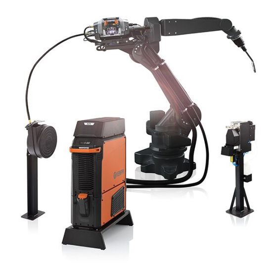
- Page 1 AX MIG Welder Operating manual - EN AX MIG Welder © Kemppi 1921900 / 2318...
-
Page 2: Table Of Contents
1.3 R500 wire feeders 1.3.1 Wire feed mechanism 1.3.2 Wire feeder peripheral connector 1.3.3 Wire feeder control cable connector 1.4 AX MIG Welder interconnection cable 1.5 RCM (Robot Connectivity Module) 1.6 Cooling unit (optional) 2. Installation 2.1 Installing power source mains plug 2.2 Connecting to AX Manager user interface... - Page 3 2.26 How to get welding programs 2.27 Fieldbus control tables 2.27.1 AX MIG 1: AX MIG Welder default fieldbus control table 2.27.2 KEMPPI 1: KempArc Pulse compatibility fieldbus control table 2.27.3 KEMPPI 4: A7 MIG Welder compatibility fieldbus control table 2.27.4 KEMPPI 6: A7 MIG Welder WeldEye compatibility fieldbus control table...
- Page 4 5.1 X5 power sources 5.2 R500 wire feeders 5.3 RCMs 5.4 Cooling unit 5.5 Add-on cards 5.6 AX MIG Welder ordering info 5.7 Wire feeder consumables 5.8 Touch sensing voltage levels 5.9 Appendix: System integration checklist © Kemppi 1921900 / 2318...
-
Page 5: General
RCM (Robot Connectivity Module) and cooling unit (optional) designed for robotic MIG/MAG welding. The user interface, AX Manager, can be accessed with an internet browser. AX MIG Welder can be integrated with all major robot brands. For robot-specific information, refer to the robot man- ufacturer's operating instructions. - Page 6 While every effort has been made to ensure that the information contained in this guide is accurate and com- plete, no liability can be accepted for any errors or omissions. Kemppi reserves the right to change the spe- cification of the product described at any time without prior notice. Do not copy, record, reproduce or transmit the contents of this guide without prior permission from Kemppi.
-
Page 7: Equipment Description
AX MIG Welder Operating manual - EN 1.1 Equipment description AX MIG Welder has multiple power source and two wire feeder options to choose from. X5 power sources (400 A): • X5 Power Source 400 >> Standard power source with support for automatic 1-MIG process as well as MAX Speed and MAX Cool pro- cesses •... - Page 8 Operating manual - EN Robot gun mounts: For information on robot gun mounts, refer to the gun mount manufacturer's operation instructions. Welding programs: For information on selecting welding programs, contact your local Kemppi dealer. Optional accessories: • Gun cleaning station •...
-
Page 9: X5 Power Source 400 And
AX MIG Welder Operating manual - EN 1.2 X5 Power Source 400 and 500 This section describes the structure of X5 Power Source 400 and X5 Power Source 500 models. Front Indicator panel * Transportation handle (not intended for mechanical lifting) Front locking interface (locking e.g. - Page 10 AX MIG Welder Operating manual - EN Rear Power switch Voltage sensing cable connector (Pulse+ power sources only) Control cable connector Control cable connector Mains cable Rear locking interface >> For locking e.g. on top of the cooling unit Earth return cable connector, minus (-) connector Welding current cable connector, plus (+) connector.
-
Page 11: R500 Wire Feeders
AX MIG Welder Operating manual - EN 1.3 R500 wire feeders This section describes the structure of R500 Wire Feeder EUR and R500 Wire Feeder EUR+. R500 Wire Feeder EUR, front Euro connector for welding cable connection Peripheral connector for welding gun auxiliary products... - Page 12 AX MIG Welder Operating manual - EN R500 Wire Feeder EUR+, front Euro connector for welding cable connection Compressed air outlet connection (for gun cleaning only) Peripheral connector for welding gun auxiliary products Welding current cable connector, positive (+) connector.
-
Page 13: Wire Feed Mechanism
AX MIG Welder Operating manual - EN R500 Wire Feeder EUR and R500 Wire Feeder EUR+, top 11. Gas test button 12. Air blow button (usable in R500 Wire Feeder EUR+ only) 13. Wire inch backward button >> Drives the filler wire backward (with arc off) 14. -
Page 14: Wire Feeder Peripheral Connector
AX MIG Welder Operating manual - EN For installing the feed rolls, refer to "Installing feed rolls" on page 57. For installing the wire guide tubes, refer to "Installing wire guide tubes" on page 52. 1.3.2 Wire feeder peripheral connector This section describes the order and purpose of the pins in the peripheral connector used for connecting welding gun auxiliary products. - Page 15 AX MIG Welder Operating manual - EN A. Power supply GND B. Data in/out C. Power supply (+48 V) D. Wire feeder ID (1 / 2) E. Touch sensor voltage (+50...+200 V) F. Reserved for future use G. Reserved for future use.
-
Page 16: Ax Mig Welder Interconnection Cable
Operating manual - EN 1.4 AX MIG Welder interconnection cable The AX MIG Welder interconnection cables come in multiple different lengths and configurations to suit your equipment setup. For installing cables, refer to "Connecting cables to power source and RCM" on page 51 and "Connecting cables to wire feeder"... - Page 17 AX MIG Welder Operating manual - EN Wire feeder end of interconnection cable Voltage sensing cable (required for WiseThin+ and WiseRoot+ processes) Shielding gas hose Welding current cable Wire feeder control cable. Wire feeder end of interconnection cable - water cooling...
-
Page 18: Rcm (Robot Connectivity Module)
AX MIG Welder Operating manual - EN 1.5 RCM (Robot Connectivity Module) RCM handles the communication between the welding system and the robot. For connecting cables, refer to "Connecting cables to power source and RCM" on page 51. Wire feeder control cable connector... - Page 19 AX MIG Welder Operating manual - EN Stop switch terminal Backup power supply terminal Ethernet 1 (LAN 1) 10. Ethernet 2 (LAN 2). © Kemppi 1921900 / 2318...
-
Page 20: Cooling Unit (Optional)
AX MIG Welder Operating manual - EN 1.6 Cooling unit (optional) Front Cooler container cap Cooling liquid level indicator Front locking interface (for locking on the stand) Front locking interface (for locking to the power source) Rear locking interface (for locking to the power source) Cooling liquid circulation button >>... -
Page 21: Installation
When installing the full set of equipment stacked as a tower – water cooler at the bottom, power source in the middle and RCM at the top – always install and secure the equipment onto a Kemppi stand compatible with AX MIG Welder or secure the equipment to other adequate support on site. -
Page 22: Installing Power Source Mains Plug
AX MIG Welder Operating manual - EN 2.1 Installing power source mains plug Only an authorized electrician is allowed to install the mains cable and plug. Do not connect the machine to the mains before the installation is complete. Install the mains plug according to the power source and site requirements. -
Page 23: Connecting To Ax Manager User Interface
AX MIG Welder Operating manual - EN 2.2 Connecting to AX Manager user interface This section describes how to connect to the AX Manager user interface for the first time (or after a factory reset) with the default network settings. -
Page 24: Installing Equipment On Stand (Optional)
AX MIG Welder Operating manual - EN 2.3 Installing equipment on stand (optional) The welding equipment can be installed with or without the cooling unit on a dedicated stand (available as an access- ory). For more information on installing the power source on top of the cooling unit, refer to "Installing cooling unit (optional)"... -
Page 25: Installing Cooling Unit (Optional)
AX MIG Welder Operating manual - EN 2.4 Installing cooling unit (optional) The cooling unit must be installed by authorized service personnel. Tools needed: Remove the small connector cover in the rear of the power source. Route the cooling unit's connection cables so that they remain accessible through the next steps. - Page 26 AX MIG Welder Operating manual - EN Fix the units together with two screws in the front (M5x12) and two screws in the rear (M5x12). Connect the cooling unit cables. Do not use force, but make sure the connectors are properly connected.
- Page 27 AX MIG Welder Operating manual - EN Replace the small connector cover. Install the coolant filter delivered with the cooling unit to the coolant inlet connector. © Kemppi 1921900 / 2318...
-
Page 28: Installing Rcm On Power Source (Optional)
AX MIG Welder Operating manual - EN 2.5 Installing RCM on power source (optional) Tools needed: Remove the power source top cover screws. Place the fixing plates to the power source and secure them with the screws provided. © Kemppi... - Page 29 AX MIG Welder Operating manual - EN Slide RCM into place. Fix the units together with the fixing bracket and screw. © Kemppi 1921900 / 2318...
-
Page 30: Mounting Wire Feeder On Robot Arm
AX MIG Welder Operating manual - EN 2.6 Mounting wire feeder on robot arm To mount the wire feeder on the robot arm, use a two-part mounting bracket. Mounting brackets are available for the most commonly used welding robots. For a complete list of the available brackets, refer to the product catalog at Kemppi.com. -
Page 31: Removing And Attaching Rcm Top Cover
AX MIG Welder Operating manual - EN 2.7 Removing and attaching RCM top cover This section describes how to remove and attach the RCM top cover. Tools needed: To remove the RCM top cover: Loosen the screws on both sides of the RCM case. - Page 32 AX MIG Welder Operating manual - EN © Kemppi 1921900 / 2318...
-
Page 33: Routing Cables Into Rcm
AX MIG Welder Operating manual - EN 2.8 Routing cables into RCM RCM has several cable inlets for different sized cables: one cable inlet with a cable clamp (used for strain relief) and three cable inlets with grommets. For instructions on removing and attaching the RCM top cover, refer to "Removing and attaching RCM top cover" on page 31. - Page 34 AX MIG Welder Operating manual - EN © Kemppi 1921900 / 2318...
-
Page 35: Connecting Pe (Protective Earth) Wire (Optional)
AX MIG Welder Operating manual - EN 2.9 Connecting PE (protective earth) wire (optional) If RCM is installed on the power source with the official fixing bracket, the PE wire is not needed. For the RCM part descriptions, refer to "RCM (Robot Connectivity Module)" on page 18. -
Page 36: Installing Fieldbus Module (Optional)
AX MIG Welder Operating manual - EN 2.10 Installing fieldbus module (optional) Fieldbus communication between the welding system and the robot can be implemented with Anybus CompactCom M40 fieldbus modules (Anybus is a registered trademark of HMS Industrial Networks). The supported fieldbuses are: •... - Page 37 AX MIG Welder Operating manual - EN Remove the cable clamp by unscrewing the fixing screws. Pass the fieldbus module cable through the aperture and connect it to the fieldbus module. Depending on the fieldbus module, the cable may be different.
-
Page 38: Removing Fieldbus Module
AX MIG Welder Operating manual - EN 2.11 Removing fieldbus module This section describes how to remove a fieldbus module. For instructions on removing and attaching the RCM top cover, refer to "Removing and attaching RCM top cover" on page 31. - Page 39 AX MIG Welder Operating manual - EN For information on installing a fieldbus module, refer to "Installing fieldbus module (optional)" on page 36. © Kemppi 1921900 / 2318...
-
Page 40: Installing Add-On Cards (Optional)
The wiring of add-on cards is customer-specific, therefore this section gives only examples of the wiring. Add-on cards require a separate 24 V power supply that is not delivered with the AX MIG Welder equipment. Turn off the power source before installing add-on cards. - Page 41 AX MIG Welder Operating manual - EN The figure below displays an overview of a digital IO add-on card. The In/Out LEDs (*) indicate the input and output states (LED is lit when the input/output is active). Digital IO add-on card terminals:...
- Page 42 Power supply configuration Each digital IO add-on card requires an external power supply (not delivered with the AX MIG Welder equipment). The external power supply’s minimum supply current is determined based on the output current taken from the outputs and the minimum current used by the digital IO add-on card.
- Page 43 AX MIG Welder Operating manual - EN 1. 24 V 2. Digital input 1, 3, 5, 7 / digital input 9, 11, 13, 15 3. 24 V 4. Digital input 2, 4, 6, 8 / digital input 10, 12, 14, 16 The following figure displays an input wiring example: ©...
-
Page 44: Add-On Card Combinations For Digital Robot Control
AX MIG Welder Operating manual - EN 2.12.2 Add-on card combinations for digital robot control For digital robot control, the robot is connected to RCM with two digital add-on cards and the 'Communication' para- meter is set to 'Digital robot control' in the "Robot settings" on page 125 view. -
Page 45: Connecting Touch Sensor Fast Output (Optional)
AX MIG Welder Operating manual - EN 2.13 Connecting touch sensor fast output (optional) The RCM main board is equipped with a touch sensor fast output which enables transmitting the touch sensing status signal to the robot faster than via the fieldbus connection. -
Page 46: Connecting Backup Power Supply (Optional)
AX MIG Welder Operating manual - EN 2.14 Connecting backup power supply (optional) The backup power supply is used to ensure that the fieldbus connection stays active even when the main current of the welding power source is cut off. When the backup power supply is used, all control functions are disabled. -
Page 47: Connecting Door Switch (Optional)
The RCM door switch terminal is intended for door switches that have two normally closed (NC) electrical contacts. The door switch is not delivered with the AX MIG Welder system. Turn off the power source before connecting the door switch. -
Page 48: Connecting Stop Switch (Optional)
The RCM stop switch terminal is intended for stop switches that have two normally closed (NC) electrical contacts. The stop switch is not delivered with the AX MIG Welder system. Turn off the power source before connecting the stop switch. -
Page 49: Connecting Cables To Wire Feeder
AX MIG Welder Operating manual - EN 2.17 Connecting cables to wire feeder For the wire feeder connector descriptions and their locations, refer to "R500 wire feeders" on page 11. Model-specific variations occur in the connectors. Front Connect the control cable for welding gun auxiliary devices (1) to the peripheral connector. - Page 50 AX MIG Welder Operating manual - EN Push the shielding gas hose (1) to the connector so that it locks down. Connect the wire feeder control cable (2) to the connector. R500 Wire Feeder EUR+ : To use the WiseThin+ or WiseRoot+ process, connect the voltage sensing cable from the workpiece (3) to the connector.
-
Page 51: Connecting Cables To Power Source And Rcm
AX MIG Welder Operating manual - EN 2.18 Connecting cables to power source and RCM This section describes the cable connections in the power source, RCM and the optional cooling unit. For the connector descriptions and their locations, refer to "X5 Power Source 400 and 500" on page 9 and "RCM (Robot Connectivity Mod- ule)"... -
Page 52: Installing Wire Guide Tubes
AX MIG Welder Operating manual - EN 2.19 Installing wire guide tubes This section describes the installation of the wire guide tubes. Select the wire guide tubes according to the tables here: "Wire feeder consumables" on page 172. Tools needed: Release the pressure handles on the wire feed mechanism. - Page 53 AX MIG Welder Operating manual - EN First time installation only: Detach the pressure roll mounting pins and drive roll mounting caps. Insert the inlet guide tube and tighten the locking tip. Turn the locking clip aside and insert the middle guide tube in its slot. Ensure that the mark arrow points to the wire running direction.
- Page 54 AX MIG Welder Operating manual - EN Turn the locking clip back to lock down the middle guide tube. Push the outlet guide tube in its place. © Kemppi 1921900 / 2318...
-
Page 55: Removing Wire Guide Tubes
AX MIG Welder Operating manual - EN 2.20 Removing wire guide tubes When removing the outlet guide tube, the welding gun must be detached. Tools needed: Release the pressure handles on the wire feed mechanism and remove the filler wire from the system. - Page 56 AX MIG Welder Operating manual - EN Loosen the inlet guide tube's locking tip and remove the inlet guide tube. Turn the locking clip aside to free the middle guide tube and remove the middle guide tube from its slot.
-
Page 57: Installing Feed Rolls
AX MIG Welder Operating manual - EN 2.21 Installing feed rolls Always ensure that the feed rolls are suitable for the filler wire (diameter and material) in question. Select the wire feed rolls according to the tables here: "Wire feeder consumables" on page 172. - Page 58 AX MIG Welder Operating manual - EN Detach the pressure roll mounting pins and drive roll mounting caps. Install the drive rolls. Align the cut on the drive rolls' bottom with the pin on the drive shaft. Attach the drive roll mounting caps.
-
Page 59: Removing Feed Rolls
AX MIG Welder Operating manual - EN 2.22 Removing feed rolls Open the wire feeder top cover. Release the pressure handles on the wire feed mechanism. Open the pressure roll locking arms. Pull the pressure roll mounting pins off. © Kemppi... - Page 60 AX MIG Welder Operating manual - EN Remove the pressure rolls. Pull the drive roll mounting caps off and remove the drive rolls. For information on installing feed rolls, refer to "Installing feed rolls" on page 57. © Kemppi 1921900 / 2318...
-
Page 61: Mounting Welding Gun
AX MIG Welder Operating manual - EN 2.23 Mounting welding gun Fasten the welding gun securely to the robot arm using a robot gun mount. For mounting instructions, refer to the gun manufacturer's instructions. © Kemppi 1921900 / 2318... -
Page 62: Installing Wire
AX MIG Welder Operating manual - EN 2.24 Installing wire This section describes how to install filler wire on the R500 wire feeder. Install the welding gun to the wire feeder before installing the wire. When changing the wire, remove the remaining filler wire from the welding gun and wire feed mechanism. - Page 63 AX MIG Welder Operating manual - EN Guide the filler wire through the inlet guide tube, middle guide tube and into the outlet guide tube, which feeds the filler wire to the welding gun. Push the filler wire by hand through the euro connector.
- Page 64 AX MIG Welder Operating manual - EN Close the pressure handles. Press the Wire inch forward button to drive the filler wire into the welding gun. Stop when the wire reaches the welding gun's contact tip. (For welding gun operating instructions, refer to the gun manufacturer's operating manual.)
- Page 65 AX MIG Welder Operating manual - EN Adjust the pressure of the feed rolls with the pressure adjustment wheels. The pressure is the same for both feed roll pairs. The graduated scales on the pressure handle indicate the pressure applied to the feed rolls. Adjust the pressure of the feed rolls according to the table below.
-
Page 66: Installing Gas Bottle
- Always use an approved and tested regulator and flow meter. Contact your local Kemppi dealer for choosing the gas and the equipment. Secure the gas bottle properly in an upright position to e.g. a special holder on the wall. - Page 67 AX MIG Welder Operating manual - EN Press the gas test button again to adjust the gas flow. Use an external flow meter and regulator for measuring and adjustment. © Kemppi 1921900 / 2318...
-
Page 68: How To Get Welding Programs
Welding programs, Wise processes (WiseRoot+, WiseThin+) and MAX processes (MAX Cool, MAX Speed, MAX Position) for each individual AX MIG Welder equipment are installed at the time of purchase according to your specific welding requirements. This can be done by your local Kemppi dealer. Welding programs as well as the advanced welding fea- tures can also be added later on. -
Page 69: Fieldbus Control Tables
Operating manual - EN 2.27 Fieldbus control tables Fieldbus control tables can be used to handle the communication between AX MIG Welder and the welding robot. This section describes the supported fieldbus control tables, and the control and status parameters. -
Page 70: Ax Mig 1: Ax Mig Welder Default Fieldbus Control Table
AX MIG Welder Operating manual - EN 2.27.1 AX MIG 1: AX MIG Welder default fieldbus control table Interface number: 20 Table size: 40 bytes Control parameters (from robot to welding system) Byte Bit/Type Control parameter StartWelding RobotReadyToWeld (Not in use) - Page 71 AX MIG Welder Operating manual - EN UINT16 (Not in use) DigitalOutput1 DigitalOutput2 DigitalOutput3 DigitalOutput4 DigitalOutput5 DigitalOutput6 DigitalOutput7 DigitalOutput8 DigitalOutput9 DigitalOutput10 DigitalOutput11 DigitalOutput12 DigitalOutput13 DigitalOutput14 DigitalOutput15 DigitalOutput16 UINT16 MemoryChannel UINT16 (Not in use) UINT16 (Not in use) UINT16 (Not in use)
- Page 72 AX MIG Welder Operating manual - EN UINT16 (Not in use) UINT16 (Not in use) UINT16 (Not in use) UINT16 (Not in use) UINT16 (Not in use) UINT16 (Not in use) Status parameters (from welding system to robot) Byte Bit/Type...
- Page 73 AX MIG Welder Operating manual - EN (Not in use) (Not in use) (Not in use) (Not in use) (Not in use) (Not in use) (Not in use) (Not in use) (Not in use) (Not in use) UINT16 (Not in use)
- Page 74 AX MIG Welder Operating manual - EN UINT16 WeldingProcess UINT16 MotorCurrent UINT16 (Not in use) UINT16 GasFlowRate UINT16 WeldAssistTravelSpeed UINT16 (Not in use) UINT16 (Not in use) UINT16 (Not in use) UINT16 (Not in use) UINT16 (Not in use) UINT16 (Not in use) ©...
-
Page 75: Kemppi 1: Kemparc Pulse Compatibility Fieldbus Control Table
AX MIG Welder Operating manual - EN 2.27.2 KEMPPI 1: KempArc Pulse compatibility fieldbus control table Interface number: 1 Table size: 8 bytes Control parameters (from robot to welding system) Byte Bit/Type Control parameter UINT16 (Not in use) UINT16 (Not in use) - Page 76 AX MIG Welder Operating manual - EN CycleOn ArcOn TouchSensed PowerSourceReady Error WeldingSystemReady LocalRemote AutoManual DigitalInput1 DigitalInput2 DigitalInput3 DigitalInput4 GateDoorOpen DigitalInput6 CollisionDetected GasFlowOk UINT8 WeldingWireFeedSpeed © Kemppi 1921900 / 2318...
-
Page 77: Kemppi 4: A7 Mig Welder Compatibility Fieldbus Control Table
AX MIG Welder Operating manual - EN 2.27.3 KEMPPI 4: A7 MIG Welder compatibility fieldbus control table Interface number: 15 Table size: 16 bytes Control parameters (from robot to welding system) Byte Bit /Type Control parameter UINT16 (Not in use) - Page 78 AX MIG Welder Operating manual - EN (Not in use) (Not in use) (Not in use) Status parameters (from welding system to robot) Byte Bit /Type Status parameter UINT16 WeldingCurrent UINT16 WeldingVoltage UINT8 ErrorNumber UINT8 WeldingWireFeedSpeed Ready PowerSourceReady CycleOn ArcOn...
- Page 79 AX MIG Welder Operating manual - EN UINT16 TAST UINT16 GasFlowRate UINT8 MotorCurrent UINT8 WeldingProcess (Not in use) © Kemppi 1921900 / 2318...
-
Page 80: Kemppi 6: A7 Mig Welder Weldeye Compatibility Fieldbus Control Table
AX MIG Welder Operating manual - EN 2.27.4 KEMPPI 6: A7 MIG Welder WeldEye compatibility fieldbus control table Interface number: 17 Table size: 49 bytes Control parameters (from robot to welding system) Byte Bit/Type Control parameter UINT16 (Not in use) - Page 81 AX MIG Welder Operating manual - EN (Not in use) (Not in use) (Not in use) (Not in use) (Not in use) (Not in use) (Not in use) (Not in use) (Not in use) (Not in use) (Not in use)
- Page 82 AX MIG Welder Operating manual - EN Status parameters (from welding system to robot) Byte Bit/Type Status parameter UINT16 WeldingCurrent UINT16 WeldingVoltage UINT8 ErrorNumber UINT8 WeldingWireFeedSpeed Ready PowerSourceReady CycleOn ArcOn GasFlowOk (Not in use) (Not in use) TouchSensed GateDoorOpen Error...
- Page 83 AX MIG Welder Operating manual - EN (Not in use) (Not in use) (Not in use) (Not in use) (Not in use) (Not in use) (Not in use) (Not in use) (Not in use) (Not in use) (Not in use)
-
Page 84: Control Information
AX MIG Welder Operating manual - EN 2.27.5 Control information Control information from the robot to the welding system is transmitted as parameters and individual bits (signals) in the fieldbus control table. Control parameters Parameter Parameter value Description 0 ... 199 Controls the active memory channel. -
Page 85: Status Information
AX MIG Welder Operating manual - EN RobotReadyToWeld Robot is ready to Robot is not ready Safeguards the StartWelding bit so that welding cannot be start welding to start welding started if the robot is not ready. If this bit is not available in the selected fieldbus control table, the robot is assumed to be always ready to weld. - Page 86 AX MIG Welder Operating manual - EN CycleOn Welding cycle is not ongoing Welding cycle is ongoing Indicates whether welding cycle is ongoing. The welding cycle includes also pre gas, creep start, crater fill and post gas phases. ArcOn Welding arc is not established...
- Page 87 AX MIG Welder Operating manual - EN Watchdog Watchdog control bit is 0 Watchdog control bit is 1 Watchdog loop-back status bit that reflects the value of the watchdog control bit back to the robot. This bit is active even when the watchdog functionality is turned off.
-
Page 88: Timing Diagrams
AX MIG Welder Operating manual - EN 2.28 Timing diagrams This section describes the timing of certain functions when controlled by the robot. "Welding start and stop timing" below "Memory channel change timing" on the next page "Wire inch timing" on the next page "Touch sensor timing"... -
Page 89: Memory Channel Change Timing
AX MIG Welder Operating manual - EN 2.28.2 Memory channel change timing Changing a memory channel during welding is not recommended when changing from one process to another (e.g. from 1-MIG to Pulse). Description Typical Units Total time 2.28.3 Wire inch timing This section describes the timing for the wire inch forward and wire inch backward functions when controlled by the robot. -
Page 90: Touch Sensor Timing
AX MIG Welder Operating manual - EN 2.28.4 Touch sensor timing Touch sensor start timing Item Description Typical Units Touch sensor OFF Start response time Touch sensor ON Touch sensing tool change timing Symbol Description Typical Units Previous touch sensor tool... -
Page 91: Stop Switch Response Timing
AX MIG Welder Operating manual - EN Fast status output Touch sensor off timing Symbol Description Typical Units Touch sensor ON Control response time Touch sensor OFF 2.28.5 Stop switch response timing Symbol Description Typical Units Stop switch response time... -
Page 92: Operation
AX MIG Welder Operating manual - EN 3. OPERATION Welding is forbidden in places where there is an immediate fire or explosion hazard! The interconnection cable heats up during welding. Handle the cables with caution. Check that there is enough space for cooling air circulation in the machine vicinity. -
Page 93: Preparing Welding System For Use
Ensure that the surface contact to the table is clean of metal oxide and paint and that the clamp is firmly secured. 3.1.1 Filling cooler and circulating coolant Fill the cooler with 20-40 % coolant solution, for example, Kemppi cooling liquid. © Kemppi... -
Page 94: Calibrating Welding Cable
AX MIG Welder Operating manual - EN Open the cooler cap. Fill the cooler with coolant. Do not fill over the max. marking. Close the cooler cap. To circulate coolant: Press the coolant circulation button in the front panel of the power source. It activates the motor, which pumps the coolant to the hoses and to the welding gun. - Page 95 AX MIG Welder Operating manual - EN In AX Manager, go to Settings - Device settings and select Cable calibration and follow the on-screen instruc- tions. Check the measured values in AX Manager and repeat calibration if necessary (if, for example, the calibration failed due to poor contact between the contact tip and the work piece).
-
Page 96: Using Ax Manager
Operating manual - EN 3.2 Using AX Manager AX Manager is the user interface for controlling AX MIG Welder. AX Manager can be used with a PC, tablet and mobile device. The parameters, functions and symbols are shortcuts to the corresponding views. - Page 97 AX MIG Welder Operating manual - EN Home Memory channels Welding parameters Weld Assist Users Tools Info Robot status Logbook Weld history Device settings Network settings Fieldbus settings Robot settings Adjustment views In adjustment views you can adjust parameter values with a number pad or a slider.
-
Page 98: Home
AX MIG Welder Operating manual - EN Scaling in mobile device Scaling in tablet and PC 3.2.1 Home Home view is also the main welding view. © Kemppi 1921900 / 2318... - Page 99 AX MIG Welder Operating manual - EN Memory channel, welding program and WPS (if in use) Applied welding parameters and functions Wire feed speed Active welding process Welding voltage >> With 1-MIG process voltage fine tuning is displayed >> With Wise/MAX process a corresponding Wise/MAX parameter adjustment is displayed Configurable shortcut >>...
-
Page 100: Memory Channels
AX MIG Welder Operating manual - EN After each weld, a weld summary (Weld data) is displayed briefly. 3.2.2 Memory channels Managing memory channels The memory channel view can be accessed via the Home view or the View menu. The number of available memory chan- nels is 200. - Page 101 AX MIG Welder Operating manual - EN M anaging memory channels Open the actions menu. Select the desired action. Make further selections as required. The available actions are: • Save to: Save the current settings to another channel •...
-
Page 102: Users
AX MIG Welder Operating manual - EN • Create from programs: Create new channels based on all of the licensed welding programs available • Delete all: Delete all channels. 3.2.3 Users In the Users view you can change the user PIN code. - Page 103 AX MIG Welder Operating manual - EN Go to the Weld Assist view and select 'Next'. Select: >> The welding joint type: T-joint / lap joint / corner joint / plate+tube joint >> The welding position: PA / PB / PC / PD >>...
- Page 104 AX MIG Welder Operating manual - EN © Kemppi 1921900 / 2318...
- Page 105 AX MIG Welder Operating manual - EN Weld Assist gives you a recommendation for these welding parameters: >> Welding process >> Gas flow rate (measured at the gun end) >> Wire feed speed >> Indicative values for welding current and voltage.
-
Page 106: Welding Parameters
AX MIG Welder Operating manual - EN Save the Weld Assist’s recommendation for welding settings by selecting 'Save'. Select the memory channel slot for saving. To use the memory channel, select 'Use' in Weld Assist, or later in the Memory channels view. - Page 107 AX MIG Welder Operating manual - EN Adjusting welding parameters Select a welding parameter for adjustment. >> You can navigate in the parameter list also by selecting a phase in the start and stop curve. Adjust the welding parameter value.
- Page 108 AX MIG Welder Operating manual - EN Creep start 10 ... 100 %, AUTO, step 1 The Creep start function defines the wire Default = AUTO feed speed before the welding arc ignites, that is, before the filler wire comes in contact with the workpiece.
- Page 109 AX MIG Welder Operating manual - EN Post gas 0.0 ... 9.9 s, AUTO, step 0.1 Welding function that continues the 0.0 = OFF shielding gas flow after the arc has extin- Default = AUTO guished. This ensures that the hot weld...
- Page 110 AX MIG Welder Operating manual - EN Hot start ON/OFF Welding function that uses higher or Default = OFF lower wire feed speed and welding cur- rent at the start of the weld. After the Hot - Hot start level -50 ...
- Page 111 AX MIG Welder Operating manual - EN Post gas 0.0 ... 9.9 s, AUTO, step 0.1 Welding function that continues the 0.0 = OFF shielding gas flow after the arc has extin- Default = AUTO guished. This ensures that the hot weld...
-
Page 112: Wps
The use of digital WPS (Welding Procedure Specification, dWPS) and WeldEye cloud service require a valid Kemppi WeldEye subscription with the Welding Procedures module. The AX MIG Welder equipment includes a link to a free trial registration – featuring also a free trial option for WeldEye ArcVision. For more information on WeldEye, refer to weldeye.com... - Page 113 AX MIG Welder Operating manual - EN In AX Manager, go to the WPS view. Use the QR code reader on your mobile device to open the WeldEye web link or navigate to 'https://re- gister.weldeye.io/arcvision' on your web browser. Complete the registration process as instructed on the registration page.
- Page 114 AX MIG Welder Operating manual - EN To take a dWPS in use: Open the list of WPSs by selecting 'Select WPS'. Select the desired WPS in the list. Open the WPS details by selecting 'View'. © Kemppi 1921900 / 2318...
- Page 115 AX MIG Welder Operating manual - EN Select a weld pass on the WPS. To link the weld pass to an existing memory channel, select 'Select linked channel'. © Kemppi 1921900 / 2318...
- Page 116 AX MIG Welder Operating manual - EN Select the channel to which you are linking the weld pass. Confirm selection by selecting 'Link'. >> The memory channel set as default is activated with the 'Activate' button later on by default (it does not have to be selected in a list).
- Page 117 AX MIG Welder Operating manual - EN If the selected memory channel is not active, activate the selected weld pass and the memory channel by selecting 'Activ- ate'. The welding parameters are still manually adjustable, but the adjustment ranges defined on the active WPS are indic- ated on the screen (1).
-
Page 118: Info View
AX MIG Welder Operating manual - EN 3.2.7 Info view The Info view shows information on the device usage. Through this view it is also possible to access the error logs, list of installed welding programs, additional operating information and device info, such as activated licenses, the software version and equipment serial numbers. -
Page 119: Tools
AX MIG Welder Operating manual - EN 3.2.8 Tools Gas test Gas test is used to flush the previous shielding gas, run new shielding gas into the system, and test that the shielding gas flows through the system properly. The gas test time can be adjusted by selecting the Gas test time button. - Page 120 AX MIG Welder Operating manual - EN Parameter Description General Communication Green light: The status data transfer between the welding system and the robot works. No light: The status data transfer between the welding system and the robot does not work.
-
Page 121: Network Settings
AX MIG Welder Operating manual - EN Gas flow Green light: The gas flow rate is above the minimum gas flow rate set in AX Manager. Note that if the gas flow sensor (available in R500 Wire Feeder EUR+ only) is set to OFF, this status is OK even if the gas flow rate is below the gas flow rate set in AX Manager (for more information, refer to "Robot settings"... - Page 122 AX MIG Welder Operating manual - EN Changing settings To access your network's IP settings, select 'Configure'. Select the settings parameter for adjustment. Select the settings value. >> Depending on the settings parameter to be adjusted, refer also to the Network settings table below for more details.
-
Page 123: Device Settings
AX MIG Welder Operating manual - EN WLAN IP configuration (RCM+ only) - access point mode Parameter Value Description WLAN ON/OFF MAC address The unique address of RCM. Access point RCM acts as an access point to which other devices (PC, mobile WLAN mode device) can connect. - Page 124 AX MIG Welder Operating manual - EN Changing settings Select the settings parameter for adjustment. Select the settings value. >> Depending on the settings parameter to be adjusted, refer also to the Device settings table below for more details. Confirm the new value / selection and close the adjustment view by selecting OK.
-
Page 125: Robot Settings
AX MIG Welder Operating manual - EN Weld data average Without slopes / Entire This feature allows the user to change how the weld data aver- weld ages are calculated: with or without the slope phases in the Default = Without beginning and in the end of the weld. - Page 126 AX MIG Welder Operating manual - EN Settings Parameter Parameter value Description Simulation / Select at Simulation: Simulation is ON and the arc cannot be established. robot Select at robot: The robot makes the selection. Default = Select at robot...
-
Page 127: Fieldbus Settings
AX MIG Welder Operating manual - EN Gas flow sensor (in R500 Wire OFF/ON Gas flow sensor is used to measure the shielding gas flow rate. Feeder EUR+ only) Default = OFF When the gas flow sensor is set to OFF, the gas flow status is... - Page 128 This table lists the Modbus TCP fieldbus settings. Parameter Value Description Identification information Vendor name Kemppi Vendor identifier assigned to Kemppi. Product code Ordering code of the fieldbus module. Vendor URL www.kemppi.com Vendor's URL address. Product name AX MIG Welder Name of the welding system.
- Page 129 This table lists the Ethernet/IP fieldbus settings. Parameter Value Description Identification information 0x057B Vendor identifier assigned to Kemppi by ODVA. ODVA Vendor 0x0064 Indication of the general type of the welding system. ODVA Device type Code from which the robot identifies the welding system.
- Page 130 Profibus This table lists the Profibus fieldbus settings. Parameter Value Description Identification information Manufacturer 0x0368 Vendor identifier assigned to Kemppi by PNO (PROFIBUS Nutzerorganisation). PNO Ident number 0x11BF Manufacturer-specific identification number. Order ID Fieldbus module ordering code. Serial number Example: PSNK0012345 Serial number of the welding power source.
-
Page 131: Logbook
Parameter Value Description Identification information ETG Vendor ID 0x00FE0001 Vendor identifier assigned to Kemppi by ETG (EtherCAT Tech- nology Group). Device type 0x00000000 Identifier of the type of the welding system. Product code Code from which the robot identifies the welding system. -
Page 132: Weld History
AX MIG Welder Operating manual - EN 3.2.15 Weld history The Weld history view collects the information of the past welds into one view for later checking. To change how the weld data averages are calculated (with or without slope phases), refer to "Device settings" on page 123. -
Page 133: Applying Welding Programs
AX MIG Welder Operating manual - EN 3.2.16 Applying welding programs To select and apply a MIG welding process and program, a corresponding memory channel must be created. The use of additional welding programs and Wise and MAX features is possible with X5 standard power source. Pulse power source is required for the MAX Position (optional) process and Pulse+ power source for the WiseRoot+ (optional) and WiseThin+ (optional) processes. - Page 134 AX MIG Welder Operating manual - EN Use the filter options (e.g. material, wire material or wire diameter) to find the welding programs best suited for the purpose. If manual MIG is selected as the process, other filter and welding program selections are disabled.
-
Page 135: Weld Data
AX MIG Welder Operating manual - EN Select 'Save to'. Once ready, you can continue to the Welding parameters view to adjust the welding settings for the new channel, cre- ate a new channel or go back to the Memory channels view. - Page 136 AX MIG Welder Operating manual - EN © Kemppi 1921900 / 2318...
-
Page 137: Additional Guidance To Functions And Features
3.3 Additional guidance to functions and features This section summarizes the AX MIG Welder functions and features and how to use them. Many of the features are optional and device model specific. When the feature is device model specific, the emphasized equipment information in the beginning of the section tells its availability. -
Page 138: Wisesteel Feature
Operating manual - EN >> Fine-tune the heat output while welding in the Home view. For more information on Wise products, visit www.kemppi.com. 3.3.4 WiseSteel feature The WiseSteel welding feature is based on modifying the conventional MIG/MAG arcs to enable higher quality of welds. -
Page 139: Wiseroot+ Process
X5 Power Source Pulse+, R500 Wire Feeder EUR+ Requires the use of the voltage sensing cable (refer to "AX MIG Welder interconnection cable" on page 16). The WiseRoot+ welding process improves the quality of root pass welds. WiseRoot+ is based on accurate measurement of arc voltage. -
Page 140: Max Cool Process
AX MIG Welder Operating manual - EN The measurement data serves as input for the voltage control. The process reduces heat input, deformation and spatter. WiseThin+ is also optimal for position welding with thicker plates. >> To take WiseThin+ into use, go to AX Manager's Welding parameters view and apply WiseThin+. Optionally, go to the Memory channels view and create a new memory channel with WiseThin+ process. -
Page 141: Max Speed Process
The use of dWPS and WeldEye cloud service requires a valid Kemppi WeldEye subscription with the Welding Procedures module. The AX MIG Welder equipment includes a link to a free trial registration – featuring also a free trial option for WeldEye ArcVision. -
Page 142: Through Arc Seam Tracking (Tast)
AX MIG Welder Operating manual - EN The free trial registration includes both the WeldEye Welding Procedures and WeldEye ArcVision modules. 3.3.13 Through Arc Seam Tracking (TAST) TAST is used for providing precise welds depending on specific weld characteristics or in setups where the position of the work piece varies during repetitive tasks. -
Page 143: Usb Backup And Restore
There can be only one ZIP file on the USB memory stick inserted into the welding system at once. This can be either a dedicated firmware pack for this welding system or a welding program and license pack (matching the power source serial number). For more information on the available software and compatibility, contact your local Kemppi rep- resentative. - Page 144 AX MIG Welder Operating manual - EN The update process starts automatically. Follow the on-screen instructions. © Kemppi 1921900 / 2318...
-
Page 145: Maintenance
AX MIG Welder Operating manual - EN 4. MAINTENANCE When considering and planning routine maintenance, consider the operating frequency of the welding system and the working environment. Correct operating of the welding machine and regular maintenance helps you avoid unnecessary downtime and equip- ment failure. -
Page 146: Daily Maintenance
Check all the cables and connectors. Do not use them if they are damaged and contact service for replacements. • Check the wire feeder's feed rolls and the pressure handle. Clean and lubricate with a small quantity of light machine oil if needed. For repairs, contact Kemppi at www.kemppi.com or your dealer. Welding gun maintenance Refer to the operating instructions of the welding gun manufacturer. -
Page 147: Periodic Maintenance
AX MIG Welder Operating manual - EN 4.2 Periodic maintenance Only qualified service personnel is allowed to carry out periodic maintenance. Only an authorized electrician is allowed to carry out electrical work. Before removing the cover plate, disconnect the power source from the mains and wait for about 2 minutes for the capacitor to discharge. -
Page 148: Service Workshops
AX MIG Welder Operating manual - EN 4.3 Service workshops Kemppi Service Workshops complete the welding system maintenance according to the Kemppi service agreement. The main aspects in the service workshop maintenance procedure are: • Cleanup of the machine •... -
Page 149: Troubleshooting
AX MIG Welder Operating manual - EN 4.4 Troubleshooting The problems listed and the possible causes are not definitive, but suggest some typical situations that may turn up during normal use of the welding system. Welding system: Problem Recommended actions The welding system does not power up Check that the mains cable is plugged in properly. -
Page 150: Error Codes
AX MIG Welder Operating manual - EN Varying welding performance Check that the wire feed mechanism is adjusted properly. Blow compressed air through the wire liner to check that it is not blocked. Check that the wire liner is correct for the selected wire size and type. - Page 151 Too long welding session with high Do not shut down, let the fans cool the machine. If fans overheated power. are not running, contact Kemppi service Internal 24V Power source contains an inoperative Restart the power source. If problem persists, contact voltage is too 24V power supply unit .
- Page 152 Kemppi service. missing Welding pro- Required welding program is not Contact Kemppi service for installing welding programs. gram error installed. Rear drive roll Wire feeder’s rear drive roll is slipping. Adjust the feed roll pressure. Clean the wire lines.
- Page 153 AX MIG Welder Operating manual - EN Unsupported RCM hardware is not supported by the Update the RCM firmware. hardware current firmware. © Kemppi 1921900 / 2318...
-
Page 154: Installing And Cleaning Power Source Air Filter (Optional)
AX MIG Welder Operating manual - EN 4.5 Installing and cleaning power source air filter (optional) An optional power source air filter can be purchased separately. The air filter comes with a fixed casing designed to be mounted directly onto the power source air intake. - Page 155 AX MIG Welder Operating manual - EN Cleansing Remove the air filter from the power source by releasing the clips on the edge of the air filter casing. Blow the air filter clean with compressed air. © Kemppi 1921900 / 2318...
-
Page 156: Disposal
The owner of the equip- ment is obliged to deliver a decommissioned unit to a regional collection center, as per the instructions of local author- ities or a Kemppi representative. By applying these European Directives you improve the environment and human health. -
Page 157: Technical Data
AX MIG Welder Operating manual - EN 5. TECHNICAL DATA Technical data: • For X5 power source technical data, refer to "X5 power sources" on the next page. • For RCM technical data, refer to "RCMs" on page 168. • For add-on card technical data, refer to "Add-on cards" on page 170. -
Page 158: X5 Power Sources
AX MIG Welder Operating manual - EN 5.1 X5 power sources X5 Power Source 400 X5 Power Source 400 Feature Value Mains connection voltage 380...460 V ±10 % 3~50/60 Hz 4 mm² Mains connection cable H07RN-F 20 kVA Input power at rated max-... - Page 159 AX MIG Welder Operating manual - EN Wired communication type CAN bus Standards IEC 60974-1, -10 © Kemppi 1921900 / 2318...
- Page 160 AX MIG Welder Operating manual - EN X5 Power Source 400 Pulse X5 Power Source 400 Pulse Feature Value Mains connection voltage 380...460 V ±10 % 3~50/60 Hz 4 mm² Mains connection cable H07RN-F 20 kVA Input power at rated max-...
- Page 161 AX MIG Welder Operating manual - EN X5 Power Source 400 Pulse+ X5 Power Source 400 Pulse+ Feature Value Mains connection voltage 380...460 V ±10 % 3~50/60 Hz 4 mm² Mains connection cable H07RN-F 20 kVA Input power at rated max-...
- Page 162 AX MIG Welder Operating manual - EN X5 Power Source 400 MV Pulse+ X5 Power Source 400 MV Pulse+ Feature Value Mains connection voltage 220...230 V ±10 % 380...460 V ±10 % 3~50/60 Hz 6 mm² Mains connection cable H07RN-F...
- Page 163 AX MIG Welder Operating manual - EN Voltage supply for cooling 220...230 V, 24 V unit 380...460 V, 24 V Recommended minimum @ 400 V 25 kVA generator power Wired communication type CAN bus IEC 60974-1, -10 Standards © Kemppi...
- Page 164 AX MIG Welder Operating manual - EN X5 Power Source 500 X5 Power Source 500 Feature Value Mains connection voltage 380...460 V ±10 % 3~50/60 Hz 6 mm² Mains connection cable H07RN-F 27 kVA Input power at rated max- imum current Maximum supply current @ 380...460 V...
- Page 165 AX MIG Welder Operating manual - EN X5 Power Source 500 Pulse X5 Power Source 500 Pulse Feature Value Mains connection voltage 380...460 V ±10 % 3~50/60 Hz 6 mm² Mains connection cable H07RN-F 27 kVA Input power at rated max-...
- Page 166 AX MIG Welder Operating manual - EN X5 Power Source 500 Pulse+ X5 Power Source 500 Pulse+ Feature Value Mains connection voltage 380...460 V ±10 % 3~50/60 Hz 6 mm² Mains connection cable H07RN-F 27 kVA Input power at rated max-...
-
Page 167: R500 Wire Feeders
AX MIG Welder Operating manual - EN 5.2 R500 wire feeders Wire Feeder R500 EUR R500 EUR+ Feature Value Supply voltage 48 V 48 V Maximum supply current 1max Welding current 60 % 500 A 500 A 100 % 430 A... -
Page 168: Rcms
AX MIG Welder Operating manual - EN 5.3 RCMs RCM (Robot Connectivity Module) RCM+ Feature Value Value Supply voltage 12 ... 48 V 12 ... 48 V Supply current at maximum 1.1 ... 0.3 A 1.1 ... 0.3 A load... -
Page 169: Cooling Unit
AX MIG Welder Operating manual - EN 5.4 Cooling unit X5 Cooler 1400 Feature Value Supply voltage 380...460 V +/- 10 % Maximum supply current @ 380...460 V 0.7 A 1max Cooling power @ 1 L/min 1.4 kW Recommended coolant... -
Page 170: Add-On Cards
AX MIG Welder Operating manual - EN 5.5 Add-on cards Add-on card Digital add-on card Feature Value Number of inputs Number of outputs Supply voltage 24 V +- 10 % Minimum supply current (no outputs active) 0.1 A Maximum supply current (maximum current on outputs) 8.1 A... -
Page 171: Ax Mig Welder Ordering Info
AX MIG Welder Operating manual - EN 5.6 AX MIG Welder ordering info For AX MIG Welder ordering information and optional accessories, refer to Kemppi.com. © Kemppi 1921900 / 2318... -
Page 172: Wire Feeder Consumables
The wire feeder consumables can be ordered in Configurator.kemppi.com. In the tables, standard refers to plastic feed rolls and heavy-duty refers to metal feed rolls. The materials mentioned first refer to primary suitability and the materials mentioned inside brackets refer to secondary suitability. - Page 173 AX MIG Welder Operating manual - EN Filler wire material Filler wire diameter (mm) Feed roll identification Inlet tube Middle tube Outlet tube 0.8−0.9 W020372 W007274 W011460 Fe (MC/FC) W020373 W007275 W011461 W020374 W007276 W011462 W020375 W007277 W011463 W020376 W007278...
- Page 174 AX MIG Welder Operating manual - EN Ss, Cu (Fe) V-groove 0.8−0.9 W001047 W001048 W000675 W000676 W000960 W000961 W001049 W001050 W001051 W001052 W001053 W001054 W001055 W001056 MC/FC V-groove, knurled W001057 W001058 W001059 W001060 1.4−1.6 W001061 W001062 U-groove W001067 W001068 W001069...
-
Page 175: Touch Sensing Voltage Levels
AX MIG Welder Operating manual - EN 5.8 Touch sensing voltage levels Touch sensing provides eight software selectable DC voltage levels. The following table lists all setups and their relative voltage levels. The accuracy of all values in the table except for the nominal voltage is +/-5 %. -
Page 176: Appendix: System Integration Checklist
AX MIG Welder Operating manual - EN 5.9 Appendix: System integration checklist This section lists the tasks necessary to complete the system integration. Each task is a link to the corresponding instruc- tions. Installation: Install the power source mains plug...
Need help?
Do you have a question about the AX MIG Welder and is the answer not in the manual?
Questions and answers