Table of Contents
Advertisement
Quick Links
Advertisement
Table of Contents

Related Manuals for Kemppi Kemppi A7 MIG Welder 350


Summary of Contents for Kemppi Kemppi A7 MIG Welder 350
- Page 1 A7 MIG Welder A7 MIG Welder 350, 450...
-
Page 2: Table Of Contents
4.3.9 Settings – Fieldbus................© Kemppi Oy 2017... - Page 3 ..................© Kemppi Oy 2017...
-
Page 4: Introduction
PC computer. For the sake of confidentiality, it is not recommended to connect the A7 MIG Welder system to any public or internal network. Kemppi is not liable for errors or damages resulting from non-compliance of this recommendation. © Kemppi Oy 2017... -
Page 5: Installation
• Protect the machine against heavy rain and direct sunshine. Do not operate the machine in the rain. Never aim the spray of sparks from a grinding machine toward the equipment. © Kemppi Oy 2017 A7 MIG Welder 1735... -
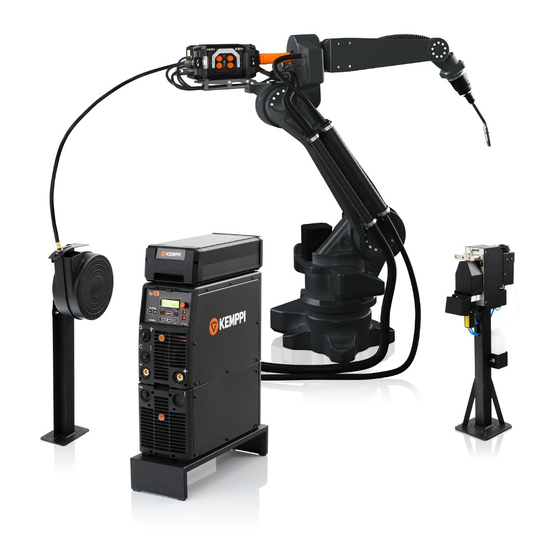
Page 6: System Overview
( + ) The A7 MIG Power Source 350/450 is designed for demanding professional use. The power source is suitable for pulsed MIG/MAG, 1-MIG, and also for WiseRoot+ and WiseThin+ processes. © Kemppi Oy 2017 A7 MIG Welder 1735... -
Page 7: Robot Interface Unit
For connecting the cables of the robot interface unit, see A7 MIG Welder Integration guide. © Kemppi Oy 2017 A7 MIG Welder 1735... -
Page 8: User Interfaces
See Section 4.3, “Web user interface” The setup panel has a menu display, soft buttons and a details. control knob for easy navigation and control. See Section 4.2, “Setup panel” for details. © Kemppi Oy 2017 A7 MIG Welder 1735... - Page 9 For more source information on using the wire feeder and its functions, see 11. Arc measurement cable connector for the Section 4.7, “Wire Feeder”. workpiece clamp 12. Wire liner connector © Kemppi Oy 2017 A7 MIG Welder 1735...
- Page 10 Shielding gas hose Welding cable Control cable The cooling hoses B and C run outside the wire feeder. See the A7 Welder Integration guide for more detailed information on connecting the wire feeder. © Kemppi Oy 2017 A7 MIG Welder 1735...
-
Page 11: Mig Guns
The robot mount Type 2 is used for connecting the robot and the welding gun. The device acts three-dimensionally and is adaptable to all types of robots and for handling machines via a robot flange. © Kemppi Oy 2017 A7 MIG Welder 1735... -
Page 12: Cooling Unit
This unit is equipped with a filter and a flow switch in the return channel to ensure uninterrupted cooling operation. The operation is controlled by software. See the MIG Welder Integration guide for system configuration options. © Kemppi Oy 2017 A7 MIG Welder 1735... -
Page 13: I/O Device
4 outputs, resulting in the total of 8 inputs and 8 outputs when equipped. See the A7 MIG Welder Integration guide for electrical characteristics and more detailed information on the I/O device connection and configuration. © Kemppi Oy 2017 A7 MIG Welder 1735... -
Page 14: Using The Welder
1 to 10 minutes after Up / down arrows welding, depending on the heat effect of the completed Control knob cycle. Menu shortcut keys LCD display Soft key buttons © Kemppi Oy 2017 A7 MIG Welder 1735... -
Page 15: Button Functions
The function is indicated by a text in the Navigate in the menus up and down by pressing these LCD display just above the buttons, for example BACK, buttons. EXIT, SELECT, OK, SAVE or NEW. © Kemppi Oy 2017 A7 MIG Welder 1735... -
Page 16: Main Menu
Match™ functions and the special enhanced arc performance solution, see the wire Edit channel Open a memory channel wizard and create, modify and delete feeder's operating manual or the Kemppi website at www.kemppi.com. memory channels. Edit channel (Main menu 1/8) User settings Select, add, edit and delete users (requires login). - Page 17 Erase channel Make this channel empty by erasing all data from the channel. See the tables Welding parameters Welding functions for more information. © Kemppi Oy 2017 A7 MIG Welder 1735...
- Page 18 These are system limits. Actual limits come from the selected welding curve. and a higher value results in a rougher arc. These are system limits. Actual limits come from the selected welding curve. © Kemppi Oy 2017 A7 MIG Welder 1735...
- Page 19 0.4 - 8.0 Hz, CURVE CURVE Adjust the frequency of the double pulse, or use the value from the welding curve. These are system limits. Actual limits come from the selected welding curve. © Kemppi Oy 2017 A7 MIG Welder 1735...
- Page 20 Control the arc behavior in short circuit. A lower value results in a softer arc and a higher value results in a rougher arc. These are system limits. Actual limits come from the selected welding curve. © Kemppi Oy 2017 A7 MIG Welder 1735...
- Page 21 9/10 Start power -9 … 9 Adjust the arc ignition power. 10/10 WiseIgnition ON, OFF Set the touch sense ignition on and off. © Kemppi Oy 2017 A7 MIG Welder 1735...
-
Page 22: User Settings
All memory channels (0-199) are restored from backup. Setup settings remain as they are. Restore to factory All memory channels and their backups are removed. All settings are set to default factory values. © Kemppi Oy 2017 A7 MIG Welder 1735... - Page 23 11/20 Post gas time 0.0 - 9.9 s, CURVE Override the post gas time of CURVE the welding curve, or let the system use the curve value. © Kemppi Oy 2017 A7 MIG Welder 1735...
- Page 24 0 – 100 % Set the amount of Hydrogen (H2) in the mixture. 0 – 100 % Set the amount of Helium (He) in the mixture. This setting applies only to manual welding. © Kemppi Oy 2017 A7 MIG Welder 1735...
-
Page 25: A7 Mig Wire Feeder
5.0 m/min Set the wire feed speed in 0.05 m/min steps from 0.5 to 5.0 m/min and in 0.1 m/min steps above 5.0 m/min. WF motor Displays the motor current during the test. © Kemppi Oy 2017 A7 MIG Welder 1735... - Page 26 Select the signal polarity of the fast hardware output. The low-active signal pulls the output to 0 V on logical ’1’ state and the high-active signal releases the output on logical ’1’ . The signal is pulled up to 24 V by a resistor when released. © Kemppi Oy 2017 A7 MIG Welder 1735...
- Page 27 View the current gateway when the DHCP is on. The Web UI does not use the gateway address, so it is not necessary to set up this value when the DHCP is off. For more information, see the A7 MIG Welder Integration guide. © Kemppi Oy 2017 A7 MIG Welder 1735...
-
Page 28: Web User Interface
It allows the user to take corner of the window and can be used to show and hide actions related to the notification and disappears after the side bar. one of the buttons has been clicked. © Kemppi Oy 2017 A7 MIG Welder 1735... -
Page 29: Welding Display
Then click either on Run wire backward Run wire forward button to start the test. The button has to be kept pressed down throughout the whole test. Releasing the button stops the test. © Kemppi Oy 2017 A7 MIG Welder 1735... -
Page 30: About
To delete a channel, click on the channel name. A delete button will appear on the right side of the name box. Click on the button and confirm delete in a pop-up window. © Kemppi Oy 2017 A7 MIG Welder 1735... - Page 31 WiseThin+ welding process the selection easier by using material group, wire, wire diameter and shielding gas. WiseRoot+ welding process 1-MIG welding process Pulse welding process Double pulse welding process © Kemppi Oy 2017 A7 MIG Welder 1735...
- Page 32 Post gas time CURVE or SET VALUE and adjusting the • select Start power level by using the slider. value by using the slider bar. • select Touch sense ignition option OFF or ON © Kemppi Oy 2017 A7 MIG Welder 1735...
- Page 33 • select Touch tool WELDING WIRE, GAS NOZZLE or SELECT AT ROBOT by clicking on the buttons. • select Fast output polarity LOW-ACTIVE or HIGH-ACTIVE by clicking on the buttons. © Kemppi Oy 2017 A7 MIG Welder 1735...
-
Page 34: Settings - Users
DELETE button and confirming the delete in the pop-up dialog. • reset PIN code to 0000 by clicking on the user’s RESET PIN button. Section 4.4 "User identification" for more information. © Kemppi Oy 2017 A7 MIG Welder 1735... -
Page 35: Settings - Network
Accessing this view requires administrator or service supervisor rights. supervisor rights. Changing the network settings affects your access to Changing the fieldbus settings affects the the web user interface. communication between the welder system and the robot. © Kemppi Oy 2017 A7 MIG Welder 1735... -
Page 36: Settings - Backup, Restore And Reset
Users Network options the desired on Kemppi's web site at www.kemppi.com. items to restore and then press the Restore button. • reset all welding system settings and memory channels by clicking on the Factory reset button. -
Page 37: Overview
In the initial state, there is only one user account called “Admin” in the system. The PIN code of the Admin user is ‘0000’ (four zeroes) by default. © Kemppi Oy 2017 A7 MIG Welder 1735... -
Page 38: Turning User Identification System On
See Subsection 4.4.7 "Changing pin code" The user interface will go to a login page automatically. more information. Select an appropriate username and provide a PIN code to log in. © Kemppi Oy 2017 A7 MIG Welder 1735... -
Page 39: Deleting A User
On the page, enter the old PIN code in the first box and the new PIN code twice in the boxes below. Press the Change PIN button. The PIN code is now changed. © Kemppi Oy 2017 A7 MIG Welder 1735... -
Page 40: Resetting Pin Code
The web user interface will redirect you to the login page. When a user has already logged in, follow the logout and login instructions to change yourself as the active user. © Kemppi Oy 2017 A7 MIG Welder 1735... -
Page 41: Touch Sensor
The software enables configuration and control. Configuration is available in the setup panel and in the web user interface. The touch sensor is controlled by the welding robot using the digital robot interface. © Kemppi Oy 2017 A7 MIG Welder 1735... - Page 42 The touch sensor cannot be used when the welding cycle is on. Figure 4.20 Touch sensing system © Kemppi Oy 2017 A7 MIG Welder 1735...
-
Page 43: Voltage Source, Levels And Safety
Table 4.19, “Voltage levels” describes all setups and their relative voltage levels. The accuracy of all values in the table except the nominal voltage is ±5 %. © Kemppi Oy 2017 A7 MIG Welder 1735... -
Page 44: Touch Tool
Press the Save button in the dialog to save the settings. Figure 4.22 Gas nozzle used as touching tool Figure 4.21 Welding wire used as touching tool © Kemppi Oy 2017 A7 MIG Welder 1735... -
Page 45: Configuring Touch Tool
The TAST function is always available in the digital the welding current. robot interface and therefor it does not have any configuration parameters in the web user interface or in the setup panel. © Kemppi Oy 2017 A7 MIG Welder 1735... -
Page 46: Collision Sensor
E, and the ground for the signal is in the pin H. See the A7 MIG Welder Integration guide for more information about connecting the collision sensor. Figure 4.25 Collision sensing system © Kemppi Oy 2017 A7 MIG Welder 1735... -
Page 47: Setting Collision Sensor On And Off
When turned on, additional settings appear. Save Reset changes buttons will appear at the bottom. turned on, additional settings appear. Press the Save button in the dialog to save the settings. © Kemppi Oy 2017 A7 MIG Welder 1735... -
Page 48: Wire Feeder
• Connection to the robot interface has been lost. Gas test button Air blow button The system error cannot be acknowledged from the Wire retract button wire feeder buttons. Wire inch button © Kemppi Oy 2017 A7 MIG Welder 1735... - Page 49 Adjust the pressure of the feed rolls by using the adjustment screws. Figure 4.28 Mounting wire guide tubes and wire feed rolls © Kemppi Oy 2017 A7 MIG Welder 1735...
- Page 50 Figure 4.29 Wire guide tubes SP011451 SP007276 SP011452 SP007275 SP011453 SP007274 SP011454 SP007273 GT04 T Dinse 0.8 – 0.9 SP011443 SP007279 plastic SP011445 SP007278 Al, Ss SP011769 SP007277 (Fe, Mc, Fc) Outlet tube Middle tube © Kemppi Oy 2017 A7 MIG Welder 1735...
- Page 51 W006088 W006089 V-groove, knurled U-groove W001059 W001060 W006090 W006091 1.4 – 1.6 W001061 W001062 W006092 W006093 W001063 W001064 W001065 W001066 Al, (Fc, Mc, Ss, Fe) W001067 W001068 U-groove W001069 W001070 W001071 W001072 © Kemppi Oy 2017 A7 MIG Welder 1735...
-
Page 52: Arc Measurement
Figure 4.30: Arc measurement system Earth cable: Cable and clamp for workpiece Positive pole: Connection inside wire feeder Arc measurement cable in the interconnection cable set Setup and monitoring in setup panel and web user interface © Kemppi Oy 2017 A7 MIG Welder 1735... -
Page 53: Gas Flow Sensor
GasFlowOk signal. © Kemppi Oy 2017 A7 MIG Welder 1735... -
Page 54: Troubleshooting
• Check welding gun switch function • Check Euro gun collar is correctly fastened • Check gun liner is not blocked • Check contact tip, size, type, wear • Check and try alternative gun. © Kemppi Oy 2017 A7 MIG Welder 1735... -
Page 55: Error Codes
Failed to measure welding voltage using a measurement cable. The earth return piece, check the connection of the intermediate cable, and if necessary, cable on the measurement cable is disconnected or defective. replace the intermediate cable. © Kemppi Oy 2017 A7 MIG Welder 1735... -
Page 56: Cooling Unit Errors
Check coolant circulation. Switch off and restart the power the cooling unit is not connected but has been configured ON in the system. source. Contact the maintenance service if the error is not resolved. © Kemppi Oy 2017 A7 MIG Welder 1735... -
Page 57: Wire Feeder Errors
Switch off and restart the power source. Contact the maintenance service if Internal program error. The selected synergic welding curve was not found in the the error is not resolved. memory. The system memory card is detached or defective. © Kemppi Oy 2017 A7 MIG Welder 1735... -
Page 58: Robot Interface Errors
Replace the microSD memory card with the right type of card. Kingston® The microSD memory card is the wrong type. The system can be used normally, but microSDHC Class-10 10MB/s, min. 4 GB is recommended. log entries cannot be recorded. © Kemppi Oy 2017 A7 MIG Welder 1735... -
Page 59: I/O Device Errors
Input 5 reported a warning. INPUT 6 WARNING Warning Input 6 reported a warning. INPUT 7 WARNING Warning Input 7 reported a warning. INPUT 8 WARNING Warning Input 8 reported a warning. © Kemppi Oy 2017 A7 MIG Welder 1735... -
Page 60: Operation Disturbances
If the machine malfunction cannot be corrected with these measures, contact your Kemppi maintenance service workshop. Operation of the overload protection Under- and overvoltages in the mains supply... -
Page 61: Maintenance
Do not use pressure washing devices. and shafts. Clean and lubricate bearings and shafts with a Kemppi Service Workshops can also test and load firmware Only an authorized trained electrician should carry out small quantity of light machine oil if necessary. Assemble, and welding software. -
Page 62: Disposal
ROBOT 70-20-GH CABLE SHOE Interconnection cable set, 20 meters, air cooled decommissioned unit to a regional collection center, as per the instructions of local authorities or a Kemppi 6260481 ROBOT 70-20-WH CABLE SHOE Interconnection cable set, 20 meters, water cooled representative. -
Page 63: Technical Data
50 V DC / 100 W Max. apparent power 22 kVA 22 kVA Idle power 25 W 25 W Power supply for cooling unit 24 V DC / 50 VA 24 V DC / 50 VA © Kemppi Oy 2017 A7 MIG Welder 1735... - Page 64 -40 °C ... +60 °C EMC class Input voltage rating +24 V DC Input current rating 100 mA Output voltage rating +24 V DC Output current rating 100 mA Operating voltage (safety voltage) 50 V DC © Kemppi Oy 2017 A7 MIG Welder 1735...
- Page 65 And you know.
Need help?
Do you have a question about the Kemppi A7 MIG Welder 350 and is the answer not in the manual?
Questions and answers