Sign In
Upload
Download
Table of Contents
Contents
Add to my manuals
Delete from my manuals
Share
URL of this page:
HTML Link:
Bookmark this page
Add
Manual will be automatically added to "My Manuals"
Print this page
×
Bookmark added
×
Added to my manuals
Manuals
Brands
Kemppi Manuals
Welding System
A7 350
Integration manual
Kemppi A7 350 Integration Manual
Hide thumbs
1
Table Of Contents
2
3
4
5
6
7
8
9
10
11
12
13
14
15
16
17
18
19
20
21
22
23
24
25
26
27
28
29
30
31
32
33
34
35
36
37
38
39
40
41
42
43
44
45
46
47
48
49
50
51
52
53
54
55
56
57
58
59
60
page
of
60
Go
/
60
Contents
Table of Contents
Bookmarks
Table of Contents
Table of Contents
1 Introduction
2 Integration Step by Step
3 Hardware Installation
Procedures before Use
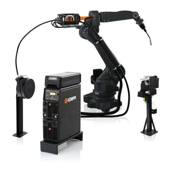
System Overview
Power Source
Cooling Unit
Wire Feeder
Welding Torch
Mounting
Push-Pull Torches
Wire Inch Button
Torch-Cleaning with Compressed Air
Touch-Sensing with the Gas Nozzle
Collision Sensor
Interconnection Cable Set
The Arc Measurement Cable
Wire Feeder Control Cable
Welding Cable
Shielding Gas Hose
Cooling Hoses
Fieldbus Communication
Ethernet (Web User Interface Server)
Emergency Input Functions
Touch Sensor Status Fast Output
Dual Wire Feeder Support
Installation
Connect the Second Wire Feeder
Powering up
4 Accessing the Web User Interface
Configuring the Network Settings
Opening the Web User Interface
5 System Configuration
Welding System, Sensors and Devices
General Settings
Wire Feed Settings
Gas Sensor Settings
General Robot Settings
Touch Sensor Settings
Collision Sensor Settings
Emergency Stop Settings
Watchdog Settings
Welding System Time
Digital Robot Interface
Fieldbus Settings
Selecting the Proper I/O Table
Setting up Scaling Values
Users
Memory Channels
System Backup
I/O Tables
KEMPPI1: Kemparc Pulse Default Table
KEMPPI2: Kemparc Pulse Customized Table
KEMPPI3: Kemparc Pulse Customized Table
KEMPPI4: A7 MIG Welder Default Table
KEMPPI5: A7 MIG Welder Table for Pulse Process Control
CUST1: Customer-Specific Table
CUST2: Customer-Specific Table
CUST3: Customer-Specific Table
CUST4: Customer-Specific Table
CUST5: Customer-Specific Table
Wirefeedspeed
Voltage
Finetuning
Dynamics
Memorychannel
Pulsecurrent
Pulsebasecurrent
Pulsefrequency
Pulselength
Weldingallowed
Simulationmode
Startwelding
Wireinch
Wireretract
Gasblow
Airblow
Touchsensortoolsel
Touchsensoron
Onlinecontrol
Watchdog
Errorreset
Weldingcurrent
Weldingvoltage
Weldingwirefeedspeed
Motorcurrent
Gasflowrate
Errornumber
6 Digital Robot Interface
Weldingprocess
Ready
Powersourceready
Coolingunitok
Programsaved
Robothascontrol
Cycleon
Arcon
Gasflowok
Maincurrenton
Currentok
Motorcurrentok
Wfspeedok
Touchsensed
Error
Collisiondetected
Toleranceerror
Wirestuck
Gatedooropen
Panellocked
Localremote
Automanual
43 6.3 Timing Diagrams
Welding Startup Timing
Welding Stop Timing
Memory Channel Change Timing
Online Control Timing
Wire Inch and Retract Timing
Touch Sensor Timing
Emergency Stop Response Timing
Advertisement
Quick Links
1
Ethernet (Web User Interface Server)
2
I/O Tables
Download this manual
EN
A7 MIG Welder
A7 MIG Welder
350, 450
Table of
Contents
Previous
Page
Next
Page
1
2
3
4
5
Advertisement
Table of Contents
Need help?
Do you have a question about the A7 350 and is the answer not in the manual?
Ask a question
Questions and answers
Related Manuals for Kemppi A7 350
Welding System Kemppi ArcFeed 200 Operating Manual
(20 pages)
Welding System Kemppi MASTERTIG AC/DC 2000 Operation Instructions Manual
(31 pages)
Welding System Kemppi MasterTig AC/DC 2000 Service Manual
(84 pages)
Welding System Kemppi A7 TIG Orbital System 300 Operating Manual
(61 pages)
Welding System Kemppi A7 TIG Orbital System 150 Operating Instructions Manual
(48 pages)
Welding System Kemppi Kemppi A7 MIG Welder 350 Operating Manual
(65 pages)
Welding System Kemppi mastertig acdc 1600 Service Manual
Mastertig acdc series (43 pages)
Welding System Kemppi A7 Cooler Operating Manual
(12 pages)
Welding System Kemppi A7 Operating Manual
Robot gun cleaning station (27 pages)
Welding System Kemppi KempGouge ARC 800 Operating Manual
(16 pages)
Welding System Kemppi A3 MIG Operating Manual
(32 pages)
Welding System Kemppi A3 Integration Manual
(22 pages)
Welding System Kemppi A7 450 Integration Manual
(60 pages)
Welding System Kemppi A5 MIG Rail System 2500 Operating Manual
(18 pages)
Welding System Kemppi AX MIG Welder Operating Manual
(176 pages)
Welding System Kemppi ArcValidator Operating Manual
(36 pages)
This manual is also suitable for:
A7 450
Table of Contents
Print
Rename the bookmark
Delete bookmark?
Delete from my manuals?
Login
Sign In
OR
Sign in with Facebook
Sign in with Google
Upload manual
Upload from disk
Upload from URL


Need help?
Do you have a question about the A7 350 and is the answer not in the manual?
Questions and answers