Table of Contents
Advertisement
Advertisement
Table of Contents
Troubleshooting

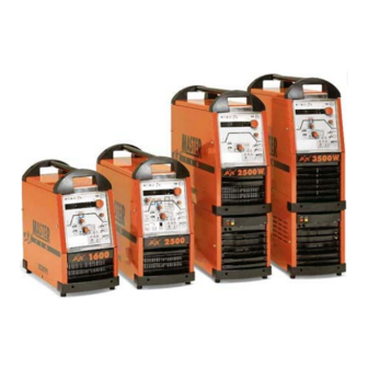
Related Manuals for Kemppi MasterTig AC/DC 2000


Summary of Contents for Kemppi MasterTig AC/DC 2000
-
Page 1: Service Manual
Service manual Ver. 1.0... - Page 2 Contents Technical data…………………………………………… 4, 5 Switches and connectors…..……………………………6-8 Function panels…..…………………………………… 8, 9 Jumper functions…........…...…………..10, 11 Error codes………………………………………………. 12 Operation principle………………………………………12-14 Block diagram…………………………………………….14 Filter cards……………………………………..…………15, 16 Filter card layout………………………...………… 16, 17 Main circuit cards………………………………………..18, 19 Main circuit cards layout………………………………...19, 20 Voltage selector switch (2500)………………………… 21 Secondary circuit components…………………………..21, 22 Diode card layout……………………………………...…23 Cooling unit……………………………………………..
- Page 3 Contents Mastertig 2000 AC/DC inverter controls……….....57-65 Sec. voltage U using low-pass filter (2000)…....65-69 Mastertig 2500 AC/DC inverter controls……….....70-73 Sec. voltage U using low-pass filter (2500)…....73-76 Mastertig 3500 AC/DC inverter controls……....….77-79 Sec. voltage U using low-pass filter (3500)…....80-83...
-
Page 4: Technical Data
Technical data Mastertig AC/DC 2000 S upply voltage 1 - 50 / 60 Hz 230 V +-10 % Connection power max. 200 A / 6,8 kVA 100 % 150 A / 4,5 kVA max. 160 A / 7,3 kVA 100 % 100 A / 4,2 kVA W elding current range 3 A / 10 V …... -
Page 5: Technical Data
Technical data Mastertig AC/DC 2500 and 2500 W 3500 W Supply voltage 3~50/60 Hz 230,400,460V +/-10% 400 V + / - 10% Loadability TIG 70% ED 250 A / 7,5 kVA 350 A / 11,7 kVA TIG 100% ED 200 A / 6,7 kVA 320 A / 9,3 kVA MMA 40% ED 250 A / 10,3 kVA... -
Page 6: Switches And Connectors
Switches and connectors Main switch Shielding gas connection TIG-torch connection Control cable connection, TIG-torch Welding current connection Return current connection Control cable connection, remote controller Supply cable Mastertig 2000 AC/DC Main switch Shielding gas connection Welding current connection Control cable connection, TIG-torch TIG-torch connection Control cable connection, remote controller Return current connection... - Page 7 Switches and connectors Main switch Shielding gas connection Welding current connection Control cable connection, remote controller Supply cable Return current connector TIG-torch connector Mastertig 2500W AC/DC Main switch Welding current connection Control cable connection, remote controller Return current connector Supply cable Shielding gas connection TIG-torch connector Mastertig 3500W AC/DC...
-
Page 8: Switches And Connectors
Switches and connectors Pressure too low -signal lamp Coolant overheating -signal lamp Test switch Torch cooling method selection Function panels TIG HF ignition /current selection TIG contact ignition/current selection Post gas time adjustment 0…100 s. Welding current downslope adj. 0…15 s. Current adj. -
Page 9: Function Panels
Function panels TIG HF ignition/ contact ignition selection AC-TIG frequency adjustment 50…200 Hz Postgas time adjustment 0…100 s. Welding current downslope time adjustment 0…15 s. Current adjustment knob/selected parameter adj Local-/remote control selection/code lock Minilog-function selection/adjustment -80…+20 % Pre gas time adjustment/code lock Welding current upslope time adjustment 0…5 s. -
Page 10: Jumper Functions
Jumper functions The power source has extra functions and selections, that can´t be seen on the display normally. The jumper functions can sometimes solve special problems. The jumper function can be a simple on/off type function or it may have an adjustable value. Jumper functions in use: 1. -
Page 11: Jumper Functions
Jumper functions Jumper Upslope angle is constant, time is dependant Upslope set time remains constant, not Upslope on the set value. depending on the set value. Downslope angle is constanttime is Downslope set time remains constant, not Downslope dependant on the set value. depending on the set value. -
Page 12: Error Codes
Error codes Err1 Power source secondary voltage is > + 90 V for overi 4 seconds.i Uin Err Net overvoltage Operation principle Mastertig AC/DC-power sources are designed for demanding professional use, suitable for TIG- /MMA welding, both AC and DC. Mastertig AC/DC-power sources are IGBT-inverter power sources, based on PWM-principle. - Page 13 Operation principle The main transformer T001 secondary voltages are rectified with a full wave rectifier V4 and the current type (DC+, DC- or AC) is chosen by IGBTs V5 and V6. Secondary circuit current is measured by shunt resistor R001. R001 T003 T001...
-
Page 14: Operation Principle
Operation principle R001 T003 T001 When the chosen current type is AC, then the IGBTs V5 and V6 are conductive one at a time, with 50…200 Hz frequency. Block diagram Spark transformer Primary Primary Main Sec. Sec. rectifying inverter transformer rectifying inverter EMI-filt. -
Page 15: Filter Cards
Filter cards + 15 V Control Information of overvoltage to control cards A002 and A001 Mastertig 2000 AC/DC Z001 To primary rectifier DC link + DC link - + 15 V Overvoltage watch Protection circuits against wrong supply voltage Mastertig 2500 AC/DC Z002... -
Page 16: Filter Cards
Filter cards Intermediate circuit DC To the primary rectifier L1, L2, L3 + 15 V Watch Aux. Transformer T002 L1, L2 primary 400 Vac Information of overvoltage to control cards A002 and A001 Mastertig 3500 AC/DC Z002 The filter cards Z001 (2000) and Z002 (2500/3500) have overvoltage protection against low energy voltage spikes coming from the net, an EMI-filter against electromagnetic disturbances conducting to the net and net overvoltage watch. -
Page 17: Filter Card Layout
Filter card layout Mastertig 2500 AC/DC Z002 X19 X2 X15 X21 Mastertig 3500 AC/DC Z002... -
Page 18: Main Circuit Cards
Main circuit cards Mastertig 2000 AC/DC Z002 The primary rectifier VG102 rectifies the net voltage. The primary choke L001 and smoothing capacitors CZ213…CZ216 filter the DC voltage. Working capacitors CZ201…CZ212, main transformer T001 and IGBT-transistor VG101 form the primary inverter. Primary circuit current is measured by current transformer T004. -
Page 19: Main Circuit Cards
Main circuit cards Mastertig 3500 AC/DC Z001 The primary rectifier VG101 rectifies the net voltage. Primary choke L001 and smoothing capacitor C002 filter the DC voltage. The primary inverter´s working capacitors are mounted onto the main circuit card Z001. Main circuit cards layout Mastertig 2000 AC/DC Z002... -
Page 20: Main Circuit Cards Layout
Main circuit cards layout Mastertig 2500 AC/DC Z001 3/E1 X9 X9 X10 X7 X7 Mastertig 3500 AC/DC Z001... -
Page 21: Secondary Circuit Components
Voltage selector switch Mastertig 2500 AC/DC S003 Voltage selector switch S003 is used to select the correct net voltage (3~ 230, 400, 460 Vac). It sets the correct transformation ratios for the main transformer T001 and voltages for auxiliary transformer T002. Secondary circuit components Mastertig AC/DCs Diode cards rectify the main transformer T001´s secondary voltages. -
Page 22: Secondary Circuit Components
Secondary circuit components Mastertig AC/DCs The shunt resistor R001 is used to measure secondary circuit current. The spark transformer T003 increases the TIG ignition spark to approx. 10 kV. C001 gives protection against the TIG ignition spark. Mastertig 2500W/3500W AC/DC Reed-relay K001 protects the liquid cooled TIG-torch, in case the cooling method selector switch is in gas-position. -
Page 23: Diode Card Layout
Diode card layout Cooling unit Mastertig 2500W AC/DC The auxiliary transformer T005 generates the 230 Vac supply voltage for the pump motor. The filter card Z004´s PTC-resistors protect the auxiliary transformer T005, if a wrong supply voltage is selected by the voltage selector switch S003. Mastertig 3500W AC/DC The auxiliary transformer T005 generates the 230 Vac supply voltage for the pump motor. -
Page 24: Filter Card Z004 Layout
Filter card Z004 layout Mastertig 2500W AC/DC Z004 Cooling unit control card A005 Coolant temperature-PTC RW301 Pressure watch S002 Too low pressure-warning lamp Pump motor control relay K1 Coolant overheat warning lamp Test switch Power supply from control card A002 Liquid-/gas cooling Control selection switch... -
Page 25: Control Card A005 Layout
Control card A005 layout Control card A001 (panel) functions Control cardA001 includes the following functional blocks: • Processor • Memories • Displays • Panel membrane switches read • Potentiometers • Net voltage watch • Fan control • Cooling unit control/watch •... -
Page 26: Control Card A001 Connectors
Control card A001 connectors X1/1 Machine size detection (1600/2500) X1/2 Set value from the remote controller X1/3 Process selecting from the remote controller X1/4 Overheat protections (PTC) X1/5 Machine size detection (2000) X1/6 Fan control X1/7 Net voltage watch from the aux. Transformer T002 secondary X1/8 X1/9 Welding current;... - Page 27 Control card A002 functions / connectors Control card A002´s functional blocks: • PWM-development • Primary IGBT control • Current and voltage adjustment loop Aux. Voltages development + 5, ± 15, + 16 and + 24 V • • Secondary overvoltage watch •...
- Page 28 Control card A002 connectors X3/1-2 Primary IGBT control X4/1-2 Primary IGBT control Aux. Transformer T002 0V Aux. Transformer T002 13 Vac Aux. Transformer T002 13 Vac X8/1 TIG ignition spark control X8/2 13 Vac X8/3 TIG-torch start detection X8/4 + 24 V X8/5 X9/1-2 Solenoid valve...
-
Page 29: Control Card A002 Layout
Control card A002 layout 3,15 AT Inverter frequency R119 Max current DC+ R118 Max current DC- Inverter frequency R118 Max current From serial number 985660/L onwards... - Page 30 Control card A003 functions / connectors Control card A003´s functional blocks: • Secondary IGBT control power stage • Remote controller connection • AC-TIG aux. Pulse developement • OCV circuit X1/1 Secondary IGBT control X1/2 + 5 V X1/3 Secondary IGBT control X1/4 - 15 V X1/5...
-
Page 31: Control Card A003 Layout
Control card A003 layout H1 (DC-) H2 (DC+/AC) X3 X5 H1 (DC-) H2 (DC+/AC) From serial number 980039/L onwards... -
Page 32: Control Card A004 Layout
Control card A004 functions / connectors Control card A004 includes these operational blocks: • TIG ignition spark development • TIG-torch start detection X1/1,3 Spark transformer primary (approx. 1 kV) X2/1,3 360 Vac from aux. Transformer T002 TIG-torch start detection X3/2 X3/3 13 Vac + 24 V... -
Page 33: Structure
Structure A003 T002 S001 A002 Z001 A001 VG102 M001, M002 T001 GA001 T003 Y001 A004 R001 VG101 VG201, VG202 Z002 Mastertig 2000 AC/DC... - Page 34 Structure A003 S001 A002 Z002 A001 T002 VG101 VG201, VG202 Z001 GA001 C003 T001 T005 S002 Z004 T003 A004 K001 S003 VG103 M001, M002 T004 A005 M003 Mastertig 2500W AC/DC...
-
Page 35: Structure
Structure A003 S001 A002 Z002 T002 A001 Y001 VG101 GA001 Z001 M001 T001 C002 S002 T003 K001 A004 VG103 T004 G002 T005 A005 M003 Mastertig 3500W AC/DC... -
Page 36: Troubleshooting
Troubleshooting The machine may be repaired only by a workshop/technician licensed and authorized for the job! First do a visual check to find possible damage points, for example loose connectors broken wires or signs of overheating. Troubleshooting diagram PROBLEM POSSIBLE CAUSE REMEDY The power source doesn´t start. -
Page 37: Troubleshooting
Troubleshooting diagram PROBLEM POSSIBLE CAUSE REMEDY The cooling unit doesn´t work. Fuse F002, 2A has burnt. Check / replace the fuse as necessary. The cooling unit doesn´t start by the test switch. Faulty aux. Transformer T005. Check the aux. Transformer T005 primary and secondary voltages. - Page 38 Net voltage operational limits Mastertig 2000 Minimum Maximum 230 Vac 165 Vac 270 Vac Mastertig 2500 Minimum Maximum 230 Vac 175 Vac 270 Vac 400 Vac 300 Vac 460 Vac 460 Vac 340 Vac 530 Vac Mastertig 3500 Minimum Maximum 400 Vac 365 Vac 460 Vac...
- Page 39 Process selection from the remote controller, voltage on connector X1/3 TIG-process MMA process Temperature watch, voltage on connector X1/4 Temperature watch in room temperature (approx.. + 20º C) Fan control, voltage on connector X1/6 Fans on Info of welding current (DC+ and AC pos. half-cycles), voltage on X1/9 DC+ 10 A, MMA DC+ 200 A, MMA DC+ 350 A, MMA...
- Page 40 Info of welding current (DC+ and AC pos. half-cycles), voltage on X1/9 AC 10 A, MMA AC 200 A, MMA AC 350 A, MMA Info of welding current (DC+ and AC pos. half-cycles), voltage on X1/11 + 15 V, MMA + 30 V, MMA + 70 V, MMA 30 Vac, MMA...
- Page 41 Torch start switch detection, voltage on connector X1/15 Torch start switch open Torch start switch closed...
- Page 42 AC TIG-welding auxiliary pulse control, voltage on connector X1/16 AC TIG-welding auxiliary pulse control AC TIG-welding auxiliary pulse control...
- Page 43 Solenoid valve Y001 control, voltage on connector X2/1 Solenoid valve open TIG HF-ignition spark control, voltage on connector X2/2 TIG ignition spark control (if the arc is not on immediately, then controls will be on in 10 ms. Intervals for 2 seconds) Set value from control card A001 (panel), voltage on connector X2/3 10 A 100 A...
- Page 44 PWM-control enabling, voltage on connector X2/4 PWM enabled PWM disabled Secondary IGBT control, voltage on connector X2/5 AC 50 Hz, MMA AC 200 Hz, TIG...
- Page 45 Secondary IGBT control, voltage on connector X2/5 Balance -70, TIG Balance +70, TIG Cooling unit control, voltage on connector X2/13 Cooling unit is off Cooling unit is on...
-
Page 46: Measurings From Control Card A002 Connector X8
Cooling unit monitorings, voltage on connector X2/14 Cooling OK Error, stop -command to cooling unit Inverter frequency selection, voltage on connector X2/15 36 kHZ 18 kHZ Measurings from control card A002 connector X8... - Page 47 TIG ignition spark control, voltage on connector X8/1 TIG ignition spark control (if the arc is not on immediately, then the controls are on in 10 ms. Intervals for 2 s.) Torch start switch detection, voltage on connector X8/3 Torch start switch open Torch start switch closed...
-
Page 48: Measurings From Control Card A002 Connector X9
Measurings from control card A002 connector X9 Solenoid valve Y001 control, voltage on connector X9/1-2 Solenoid valve open Fan control, voltage on connector X9/3-4, 6-7 Fan on Fan ”soft start”... - Page 49 Information of secondary side voltage, voltage on connector X9/5 Idling DC+, MMA Information of primary side current, voltage on connector X9/12-13 200 A 100 A 350 A...
-
Page 50: Measurings From Control Card A002 Connector X10
Measurings from control card A002 connector X10 Secondary IGBT control, voltage on connector X10/1 AC, MMA / Idling AC 200 Hz, TIG AC 50 Hz, MMA... - Page 51 Secondary IGBT control, voltage on connector X10/1 Balance -70, TIG Balance +70, TIG Set value from remote controller, voltage on connector X10/7 Without controller Minimum Maximum Process selection from remote controller, voltage on connector X10/9...
-
Page 52: Measurings From Control Card A002 Connector X10
AC TIG auxiliary pulse control, voltage on connector X10/10 AC-TIG auxiliary pulse control Measurings from control card A002 connector X11 Cooling unit monitorings, voltage on connector X11/1 Cooling OK Error, stop -command to power source... -
Page 53: Measurings From Control Card A002 Connector X20
Cooling unit control, voltage on connector X11/2 Cooling unit is not on Cooling unit is on Measurings from control card A002 connector X20 Net overvoltage measuring, voltage on connector X20/2 Net overvoltage, stop -command to power source Net voltage OK... -
Page 54: Measurings From Control Card A003 Connector X3
Measurings from control card A003 connector X3 Secondary IGBT control, voltage on connector X3/1-4 AC, MMA / idling AC 50 Hz, MMA... - Page 55 Secondary IGBT control, voltage on connector X3/1-4 AC 200 Hz, TIG Balance -70, TIG Balance +70, TIG...
-
Page 56: Measurings From Control Card A003 Connector X8
Measurings from control card A003 connector X8 Remote controller voltage reference, voltage on connector X8/2-4 Set value from remote controller, voltage on connector X8/3-4... -
Page 57: Mastertig 2000 Ac/Dc Inverter Controls
Process selection from remote controller, voltage on connector X8/1-4 Mastertig 2000 AC/DC inverter controls IGBT gate pulses, voltage on connector X3/1-2 (A002) Mastertig 2000 AC/DC IGBT gate pulse control on MMA / idling... - Page 58 IGBT gate pulses, voltage on connector X3/1-2 (A002) Mastertig 2000 AC/DC IGBT gate pulse control 10 A Mastertig 2000 AC/DC IGBT gate pulse control 50 A...
- Page 59 IGBT gate pulses, voltage on connector X3/1-2 (A002) Mastertig 2000 AC/DC IGBT gate control 100 A Mastertig 2000 AC/DC IGBT gate control 106 A (Note! Frequency!)
- Page 60 IGBT gate pulses, voltage on connector X3/1-2 (A002) Mastertig 2000 AC/DC IGBT gate control 160 A Main transformer T001 primary voltage Mastertig 2000 AC/DC T001 primary voltage 10 A...
- Page 61 Main transformer T001 primary voltage Mastertig 2000 AC/DC T001 primary voltage 50 A Mastertig 2000 AC/DC T001 primary voltage 100 A...
- Page 62 Main transformer T001 primary voltage Mastertig 2000 AC/DC T001 primary voltage 106 A (Note! Frequency!) Mastertig 2000 AC/DC T001 primary voltage 160 A...
- Page 63 Voltage after the diode cards Mastertig 2000 AC/DC After the diode card 10 A Mastertig 2000 AC/DC After the diode card 50 A...
- Page 64 Voltage after the diode card Mastertig 2000 AC/DC After the diode card 100 A Mastertig 2000 AC/DC After the diode card 106 A (Note! Frequency!)
- Page 65 Voltage after the diode cards Mastertig 2000 AC/DC After the diode card 160 A Secondary voltage U using a low-pass filter 10 kΩ 22 nF...
- Page 66 Secondary voltage U using a low-pass filter Mastertig 2000 AC/DC AC 10 A 50 Hz,MMA Mastertig 2000 AC/DC AC 100 A 50 HZ, MMA...
- Page 67 Secondary voltage U using a low-pass filter Mastertig 2000 AC/DC AC 160 A 50 Hz, MMA Mastertig 2000 AC/DC AC 10 A 100 Hz, TIG (Balance 50/50, balance automatics ON)
- Page 68 Secondary voltage U using a low-pass filter Mastertig 2000 AC/DC AC 50 A 100 Hz, TIG Mastertig 2000 AC/DC AC 100 A 100 Hz, TIG...
- Page 69 Secondary voltage U using a low-pass filter Mastertig 2000 AC/DC AC 160 A 100 Hz, TIG Mastertig 2000 AC/DC AC 200 A 100 Hz, TIG...
-
Page 70: Mastertig 2500 Ac/Dc Inverter Controls
Mastertig 2500 AC/DC inverter controls IGBT gate pulses, voltage on connector X3/1-2 (A002) Mastertig 2500 AC/DC IGBT gate control 10 A Mastertig 2500 AC/DC IGBT gate control 100 A... - Page 71 IGBT gate pulses, voltage on connector X3/1-2 (A002) Mastertig 2500 AC/DC IGBT gate control 106 A (Note! Frequency!) Mastertig 2500 AC/DC IGBT gate control 250 A...
- Page 72 Voltage over a lower IGBT Mastertig 2500 AC/DC Voltage over the lower IGBT 10 A Mastertig 2500 AC/DC Voltage over the lower IGBT 100 A...
- Page 73 Voltage over the lower IGBT Mastertig 2500 AC/DC Voltage over the lower IGBT 250 A Secondary voltage U using a low-pass filter 10 kΩ 22 nF...
- Page 74 Secondary voltage U using a low-pass filter Mastertig 2500 AC/DC AC 10 A 50 Hz, MMA Mastertig 2500 AC/DC AC 100 A 50 Hz,MMA...
- Page 75 Secondary voltage U using a low-pass filter Mastertig 2500 AC/DC AC 250 A 50 Hz, MMA Mastertig 2500 AC/DC AC 10 A 100 Hz, TIG (Balance 50/50, balance automatics ON)
- Page 76 Secondary voltage U using a low-pass filter Mastertig 2500 AC/DC AC 100 A 100 Hz, TIG Mastertig 2500 AC/DC AC 250 A 100 Hz, TIG...
-
Page 77: Mastertig 3500 Ac/Dc Inverter Controls
Mastertig 3500 AC/DC inverter controls IGBT gate pulses, voltage on connector X3/1-2 (A002) Mastertig 3500 AC/DC IGBT gate control on idle Mastertig 3500 AC/DC IGBT gate control 10 A... - Page 78 IGBT gate pulses, voltage on connector X3/1-2 (A002) Mastertig 3500 AC/DC IGBT gate control 100 A Mastertig 3500 AC/DC IGBT gate control 106 A...
- Page 79 IGBT gate pulses, voltage on connector X3/1-2 (A002) Mastertig 3500 AC/DC IGBT gate control 200 A Mastertig 3500 AC/DC IGBT gate control 350 A...
- Page 80 Secondary voltage U using a low-pass filter Mastertig 3500 AC/DC AC 10 A 50 Hz, MMA Mastertig 3500 AC/DC AC 100 A 50 Hz, MMA...
- Page 81 Secondary voltage U using a low-pass filter Mastertig 3500 AC/DC AC 200 A 50 Hz, MMA Mastertig 3500 AC/DC AC 350 A 50 Hz, MMA...
- Page 82 Secondary voltage U using a low-pass filter Mastertig 3500 AC/DC AC 50 A 100 Hz, TIG (Balance 50/50, balance automatics ON) Mastertig 3500 AC/DC AC 100 A 100 Hz, TIG...
- Page 83 Secondary voltage U using a low-pass filter Mastertig 3500 AC/DC AC 200 A 100 Hz, TIG Mastertig 3500 AC/DC AC 350 A 100 Hz, TIG...
Need help?
Do you have a question about the MasterTig AC/DC 2000 and is the answer not in the manual?
Questions and answers
режимы сварки где посмотреть
You can find information about the welding modes for the Kemppi MasterTig AC/DC 2000 in the section discussing the selection of the operation mode of the torch switch (2T/4T), fusion spot welding (SPOT WELD), broken-arc method (BROKEN ARC), and MMA welding (MMA). These details are included in the panel operation and adjustment section.
This answer is automatically generated
mastertig 2000, welding mild steel @ around 25-35 amps, weld for 5-20 mins then no gas no arc, then would have to wait for 30mins to 1hr to use again, now have to wait 24hrs or longer to be able to use , thought it was gas solenoid, replaced with new 1, still happening ..