Table of Contents
Advertisement
Quick Links
38DL PLUS
Ultrasonic Thickness Gage
User's Manual
This instruction manual contains essential information on how to use this Olympus product safely and effectively.
Before using this product, thoroughly review this instruction manual. Use the product as instructed.
Keep this instruction manual in a safe, accessible location.
DMTA-10004-01EN — Rev. D
November 2016
Advertisement
Chapters
Table of Contents
Troubleshooting

Related Manuals for Olympus 38DL PLUS


Summary of Contents for Olympus 38DL PLUS
- Page 1 DMTA-10004-01EN — Rev. D November 2016 This instruction manual contains essential information on how to use this Olympus product safely and effectively. Before using this product, thoroughly review this instruction manual. Use the product as instructed. Keep this instruction manual in a safe, accessible location.
- Page 2 Olympus Scientific Solutions Americas, 48 Woerd Avenue, Waltham, MA 02453, USA Copyright © 2010, 2011, 2015, 2016 by Olympus. All rights reserved. No part of this publication may be reproduced, translated, or distributed without the express written permission of Olympus.
-
Page 3: Table Of Contents
DMTA-10004-01EN, Rev. D, November 2016 Table of Contents List of Abbreviations ..................xi Labels and Symbols ................... 1 Important Information — Please Read Before Use ........5 Intended Use .......................... 5 Instruction Manual ........................ 5 Instrument Compatibility ..................... 6 Repair and Modification ....................... 7 Safety Symbols ........................ - Page 4 Product Description ....................19 Environmental Ratings ..................... 22 Instrument Hardware Components ............... 22 Connectors ......................... 23 Keypad Functions ..................... 25 2. Powering the 38DL PLUS ................. 31 Power Indicator ......................31 Using the AC Power ....................32 Using Battery Power ....................33 2.3.1 Battery Operating Time .................
- Page 5 DMTA-10004-01EN, Rev. D, November 2016 5.2.1 Calibrating the Instrument ................67 5.2.2 Test Blocks ....................... 70 5.2.3 Transducer Zero Compensation ..............70 5.2.4 Material Sound Velocity and the Zero Calibrations ......... 71 5.2.5 Entering a Known Material Sound Velocity ..........72 5.2.6 Locked Calibrations ..................
- Page 6 DMTA-10004-01EN, Rev. D, November 2016 Preventing False Minimum/Maximum Thickness Readings ......117 Using Alarms ......................117 Locking the Instrument ..................124 Freezing Waveforms ....................126 9. Configuring the Instrument ..............127 Configuring Measurement Parameters ..............127 Configuring System Parameters ................129 Configuring Communications ................
- Page 7 DMTA-10004-01EN, Rev. D, November 2016 11.3.2 Copying a File ....................185 11.3.3 Editing a File ....................186 11.3.4 Deleting a File or its Contents ..............188 11.3.5 Deleting a Range of IDs ................190 11.3.6 Deleting All Data Files ................190 11.4 Notes .........................
- Page 8 Sending a Screen Capture to the External microSD Card ...... 257 14.6 RS-232 Serial Data Output Formats ..............258 14.7 Resetting the Communication Parameters ............260 15. Maintaining and Troubleshooting the 38DL PLUS ......263 15.1 Providing Routine Gage Maintenance ..............263 15.2 Cleaning the Instrument ..................264 15.3 Maintaining Transducers ..................
- Page 9 DMTA-10004-01EN, Rev. D, November 2016 Index ......................... 297 Table of Contents...
- Page 10 DMTA-10004-01EN, Rev. D, November 2016 Table of Contents...
-
Page 11: List Of Abbreviations
DMTA-10004-01EN, Rev. D, November 2016 List of Abbreviations two-dimensional three-dimensional alternative current AEtoE automatic echo-to-echo automatic gain control ASCII American standard code for information interchange average comma separated variables database direct current diameter DIAG diagnostic DIFF differential EFUP environment-friendly use period EMAT electromagnetic acoustic transducer electronic stress screening... - Page 12 DMTA-10004-01EN, Rev. D, November 2016 LDPE low density polyethylene Li-ion lithium-ion loss-of-signal maximum main bang MEtoE manual echo-to-echo military minimum multi measurement measured time interval MULTI multiple NiMH nickel metal hydride part number portable document format PDSTL pedestal pulse repetition frequency polyvinylchloride single element second...
-
Page 13: Labels And Symbols
Safety-related labels and symbols are attached to the instrument at the locations shown in Figure i-1 on page 1 and Figure i-2 on page 2. If any or all of the labels or symbols are missing or illegible, please contact Olympus. CAUTION Do not touch the inner conductor of the T/R 1 and T/R 2 connectors to avoid risks of an electric shock. -
Page 14: Figure I-2 Labels And Symbols Are Attached To The Instrument
DMTA-10004-01EN, Rev. D, November 2016 Side view Back view Patent label Serial number label Instruction label (see Table 1 on page 3) Serial number label Figure i‑2 Labels and symbols are attached to the instrument Labels and Symbols... -
Page 15: Table 1 Label Contents
DMTA-10004-01EN, Rev. D, November 2016 Table 1 Label contents Serial number yynnnnnmm label Where: yy: last two digits of the production year nnnnn: 5-digit nonduplicated incrementing number representing the n production unit of this product mm: production month Instruction label Labels and Symbols... - Page 16 The EFUP for the 38DL PLUS has been determined to be 15 years. Note: The Environment-Friendly Use Period (EFUP) is not meant to be interpreted as the period assuring functionality and product performance.
-
Page 17: Important Information - Please Read Before Use
The 38DL PLUS instrument has been designed to measure thicknesses of industrial and commercial materials. WARNING Do not use the 38DL PLUS for any purpose other than its intended use. It must never be used to inspect or examine human or animal body parts. Instruction Manual This instruction manual contains complete and essential information on how to use this Olympus product safely and effectively. -
Page 18: Instrument Compatibility
GageView Interface Program — User’s Manual (P/N: 910-259-EN [U8778347]) The 38DL PLUS also works with the GageView interface program. Refer to this document for detailed information on GageView. The document is available in PDF format on the GageView CD and as online help in GageView. -
Page 19: Repair And Modification
DMTA-10004-01EN, Rev. D, November 2016 Repair and Modification Apart from the battery, the 38DL PLUS does not contain any user-serviceable parts. Opening the instrument might void the warranty. CAUTION In order to prevent human injury and/or equipment damage, do not disassemble, modify, or attempt to repair the instrument. -
Page 20: Note Signal Words
DMTA-10004-01EN, Rev. D, November 2016 DANGER The DANGER signal word indicates an imminently hazardous situation. It calls attention to a procedure, practice, or the like that if not correctly performed or adhered to will result in death or serious personal injury. Do not proceed beyond a DANGER signal word until the indicated conditions are fully understood and met. -
Page 21: Safety
For any problem or question regarding this instrument, contact Olympus or an authorized Olympus representative. • Do not touch the connectors directly by hand. Otherwise, a malfunction or electric shock may result. -
Page 22: Battery Precautions
The instrument must only be connected to a power source corresponding to the type indicated on the rating label. CAUTION If an unauthorized power supply cord is used to power the instrument or charge the batteries, Olympus cannot guarantee the electrical safety of the equipment. Battery Precautions CAUTION •... -
Page 23: Equipment Disposal
Do not expose a battery to moisture or rain; doing so could cause an electric shock. • Only use the 38DL PLUS unit or an external charger approved by Olympus to charge the batteries. • Only use batteries supplied by Olympus. -
Page 24: Weee Directive
Electronic Equipment (WEEE), this symbol indicates that the product must not be disposed of as unsorted municipal waste, but should be collected separately. Refer to your local Olympus distributor for return and/or collection systems available in your country. China RoHS China RoHS is the term used by industry generally to describe legislation implemented by the Ministry of Information Industry (MII) in the People’s Republic... -
Page 25: Emc Directive Compliance
This equipment generates and uses radio-frequency energy and, if not installed and used properly (that is, in strict accordance with the manufacturer’s instructions), may cause interference. The 38DL PLUS has been tested and found to comply with the limits for an industrial device in accordance with the specifications of the EMC directive. -
Page 26: Ices-001 (Canada) Compliance
This Class A digital apparatus complies with Canadian ICES-001. Cet appareil numérique de la classe A est conforme à la norme NMB-001 du Canada. Regulatory Information The 38DL PLUS may display a regulatory screen that lists the specific regulation with which it complies. To view the REGULATORY screen In the measurement screen, press [2nd F], [SETUP MENU] (SP MENU). -
Page 27: Technical Support
Retain packing materials, waybills, and other shipping documentation needed in order to file a damage claim. After notifying the carrier, contact Olympus for assistance with the damage claim and equipment replacement, if necessary. - Page 28 DMTA-10004-01EN, Rev. D, November 2016 Important Information — Please Read Before Use...
-
Page 29: Introduction
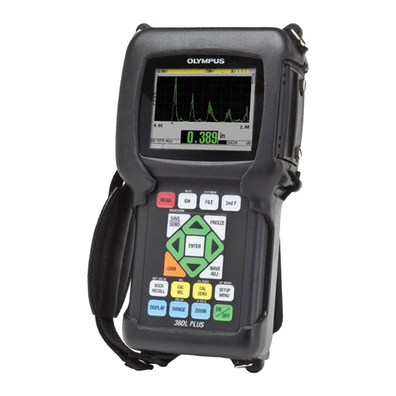
Practical measurement examples help the user become familiar with the instrument’s capabilities. IMPORTANT The list of other 38DL PLUS documents is provided in “Instruction Manual” on page 5. Figure i‑3 The 38DL PLUS instrument... - Page 30 DMTA-10004-01EN, Rev. D, November 2016 Introduction...
-
Page 31: Instrument Description
38DL PLUS instrument. Product Description The 38DL PLUS by Olympus is a hand-held ultrasonic thickness gage designed for a wide variety of thickness measurement applications. With the 38DL PLUS, you only need access to one side of a part to measure, in a nondestructive manner, the thickness of corroded, pitted, scaled, granular, and other difficult materials (see Figure 1-1 on page 19). - Page 32 You can also use single element or dual element transducers for echo-to-echo measurements. You can connect the 38DL PLUS to a printer and to a computer using the bidirectional serial USB/RS-232 communication ports. Advanced Measurement Features •...
- Page 33 DMTA-10004-01EN, Rev. D, November 2016 • Selection of password-protected lockout functions • Selectable resolution: low of 0.1 mm (0.01 in.), standard of 0.01 mm (0.001 in.), or high (optional) of 0.001 mm (0.0001 in.) [option not available for all transducers] A-Scan and B-Scan Display Options •...
-
Page 34: Environmental Ratings
DMTA-10004-01EN, Rev. D, November 2016 Environmental Ratings The 38DL PLUS is a rugged and durable instrument that you may use in harsh environments. The 38DL PLUS was designed to meet the requirement of the IP67 standard (Ingress Protection). CAUTION Olympus cannot guarantee any level of ingress protection performance once the instrument seals have been manipulated. -
Page 35: Connectors
Keypad Stand Hand strap [ON/OFF] key Figure 1‑2 The 38DL PLUS hardware components Connectors Figure 1-3 on page 23 illustrates the possible connections of the 38DL PLUS with external devices. USB/RS-232 microSD EP-MCA AC power cord Figure 1‑3 The 38DL PLUS connections... -
Page 36: Figure 1-4 The Top End Connectors
38DL PLUS. Do not use this AC power cord with other products. The DC power, USB/RS-232 communication, and Transmit/Receive probe connectors are located on the top end of the 38DL PLUS (see Figure 1-4 on page 24). USB/RS-232 serial... -
Page 37: Keypad Functions
Figure 1‑5 The connectors behind the I/O door Keypad Functions The 38DL PLUS comes either with the English, international, Chinese, or Japanese keypad (see Figure 1-6 on page 26). The functions are the same for all keypads. On the international keypad, the text labels on many keys are replaced by pictograms. In this document, keypad keys are referred to using the English label in bold and within brackets (ex.: [MEAS]). -
Page 38: Figure 1-6 The 38Dl Plus Keypads
International keypad Chinese keypad Japanese keypad Figure 1‑6 The 38DL PLUS keypads Each key indicates its primary function. The area just above some of the keys indicates a secondary key function that you can activate by first pressing [2nd F]. Throughout this document, references to a secondary function are written as follows: [2nd F], [Primary] (Secondary). -
Page 39: Table 2 Keypad Functions
The yellow keys are related to calibration. The blue keys are related to the display configuration. Table 2 on page 27 lists the key functions available from the 38DL PLUS keypad. Table 2 Keypad functions... - Page 40 DMTA-10004-01EN, Rev. D, November 2016 Table 2 Keypad functions (continued) English International Functions Freeze — Causes the displayed waveform to immediately hold until the key is pressed again. Gain — Initiates the adjustment of the gain value when using dual element transducers. Wave adjustment —...
- Page 41 DMTA-10004-01EN, Rev. D, November 2016 Table 2 Keypad functions (continued) English International Functions Transducer recall — Recalls default or custom transducer (XDCR) setups. Reference value — For some functions (ex.: differential mode or temperature compensation) opens a screen allowing you to enter a reference value.
- Page 42 DMTA-10004-01EN, Rev. D, November 2016 Table 2 Keypad functions (continued) English International Functions Special menu — Provides access to special gage parameters (clock, language, options, resets, tests, software diagnostics, instrument status). Display — Provides access to display parameters (color scheme, brightness, waveform rectification, waveform trace, and VGA output).
-
Page 43: Powering The 38Dl Plus
DMTA-10004-01EN, Rev. D, November 2016 2. Powering the 38DL PLUS This chapter describes how to operate the 38DL PLUS using different power supply options. Power Indicator The power indicator is always present on the right side of the screen. It shows the level of the battery charge and on which type of power the instrument operates (see Figure 2-1 on page 31). -
Page 44: Using The Ac Power
(see Figure 2-2 on page 32). CAUTION To avoid the risk of injuries or equipment damage, use only the AC power cord supplied with the 38DL PLUS. Do not use this AC power cord with other products. DC power plug... -
Page 45: Using Battery Power
[U8780290]). The 38DL PLUS does not recharge NiMH batteries. You must recharge AA batteries with an external battery charger (not included). NOTE The 38DL PLUS battery is not fully charged when shipped. You must fully charge the battery before operating the instrument from the battery power. Powering the 38DL PLUS... -
Page 46: Battery Operating Time
To charge the internal battery Connect the 38DL PLUS using the AC power (see “Using the AC Power” on page 32). The battery charges when the instrument is ON or OFF, but the rate of charge is slower when the instrument is ON. - Page 47 Store batteries in a cool, dry environment. • Avoid long-term storage under sunlight or in other excessively hot places such as the trunk of an automobile. • While in storage, fully recharge batteries at least once every two (2) months. Powering the 38DL PLUS...
-
Page 48: Replacing The Battery
Olympus battery (P/N: 38-BAT [U8760054]). To replace the battery Disconnect the instrument from the charger/adaptor. Ensure that the 38DL PLUS power is off. Disconnect any other cable connected to the 38DL PLUS. Remove the hand strap. Remove the protective rubber boot. Chapter 2... -
Page 49: Figure 2-5 Selecting The New Battery Type
12. Reinstall the protective rubber boot and the hand strap. 13. Press [ON/OFF] to turn on the 38DL PLUS. 14. To answer the question appearing at the bottom of the screen (see Figure 2-5 on page 37): ... - Page 50 DMTA-10004-01EN, Rev. D, November 2016 Chapter 2...
-
Page 51: Software User Interface Elements
(see Figure 3-1 on page 39). The measurement screen is the main screen of the 38DL PLUS software. From anywhere in the 38DL PLUS software, simply press [MEAS] to return to the measurement screen. -
Page 52: Figure 3-2 The Id Bar
I/O door on the right side of the instrument (see Figure 1-5 on page 25). The 38DL PLUS recognizes an external microSD memory card when you start the instrument. -
Page 53: Menus And Submenus
Figure 3‑4 The loss‑of‑signal (LOS) indicator Menus and Submenus The 38DL PLUS displays menus and submenus when you press some of the front panel keys. The menu appears at the top-left corner of the screen (see Figure 3-5 on page 42). If applicable, a submenu also appears, conveniently showing the parameters available for the highlighted menu command. -
Page 54: Parameter Screens
For example: “In the menu, select MEAS.” Parameter Screens The 38DL PLUS parameters are logically grouped in parameter screens that you access using front panel keys or menu commands. Figure 3-6 on page 43 shows the MEAS parameter screen as an example. -
Page 55: Figure 3-6 Parameter Screen Example
DMTA-10004-01EN, Rev. D, November 2016 Title bar Menu from which the screen is accessed Parameters Help text bars Figure 3‑6 Parameter screen example The title bar, located at the top of the parameter screen, indicates the parameter subject. When you access a parameter screen from a menu, a menu button appears on the left side of the title bar. -
Page 56: Selecting The Text Edit Mode
“In the MEAS screen, set MEASUREMENT MODE to THICKNESS.” Selecting the Text Edit Mode The 38DL PLUS offers two methods to edit the value of alphanumeric parameters. You can either use the virtual keyboard or the traditional method. The virtual keyboard appears on the screen to show all the available characters that you can use (see “Editing Text Parameters Using the Virtual Keyboard”... -
Page 57: Figure 3-7 Example Of The Virtual Keyboard
DMTA-10004-01EN, Rev. D, November 2016 Title bar Parameter value text Selected alphanumeric parameter Virtual keyboard Help text bars Figure 3‑7 Example of the virtual keyboard To edit an alphanumeric parameter value using the virtual keyboard Select an alphanumeric parameter. The virtual keyboard appears. Use the [], [], [], and [] keys to highlight the character that you wish to enter, and then press [ENTER]. -
Page 58: Editing Text Parameters Using The Traditional Method
DMTA-10004-01EN, Rev. D, November 2016 If you want to cancel the editing operation and return to the original parameter value, on the virtual keyboard, highlight CANCEL, and then press [ENTER]. To complete the editing of the parameter value, on the virtual keyboard, highlight DONE, and then press [ENTER]. - Page 59 DMTA-10004-01EN, Rev. D, November 2016 To edit an alphanumeric parameter value using the traditional method Select an alphanumeric parameter. Use the [] and [] keys to select the character that you wish to enter. Hold down the key to quickly cycle through the letters, numbers, and special characters. Use the [] keys to move to the next character.
- Page 60 DMTA-10004-01EN, Rev. D, November 2016 Chapter 3...
-
Page 61: Initial Setup
Italian, Norwegian, Portuguese, Czech, and a customized interface. You can also set the character delimiting the radix of a number. The 38DL PLUS includes a beep tone generator to confirm when a key is pressed and to notify you of an alarm condition. You can set the beeper on or off. -
Page 62: Selecting The Measurement Units
Press [MEAS] to return to the measurement screen. Setting the Clock The 38DL PLUS has a built-in date and time clock. You can set the date and the time and select their format. The 38DL PLUS saves all measurements value with their acquisition date. -
Page 63: Changing Display Settings
DMTA-10004-01EN, Rev. D, November 2016 To set the clock Press [2nd F], [SETUP MENU] (SP MENU). In the menu, select CLOCK. In the CLOCK screen (see Figure 4-2 on page 51): a) Set parameters to the current date and time and to the desired date and hour modes. -
Page 64: Color Schemes
4.4.1 Color Schemes The 38DL PLUS offers two standard color schemes designed to provide best display visibility in indoor or outdoor lighting conditions (see Figure 4-4 on page 53). From the measurement screen, press [DISPLAY] to access the COLOR SCHEME parameter. -
Page 65: Display Brightness
4.4.2 Display Brightness You can adjust the 38DL PLUS display brightness by selecting the backlight intensity. The display brightness can be set at 0 %, 25 %, 50 %, 75 %, and 100 %. Choosing a high percentage increases the brightness of the display. By default, the display brightness is set to 25 %. -
Page 66: Waveform Rectification
DMTA-10004-01EN, Rev. D, November 2016 The 38DL PLUS uses a transflective color display that reflects ambient light and becomes brighter in direct light. With brighter ambient conditions, you can set the display brightness to a lower percentage. NOTE Reducing the display brightness percentage increases the battery life. Battery life specifications are based on backlight brightness set to 50 %. -
Page 67: Waveform Trace
4.4.4 Waveform Trace The 38DL PLUS can display the waveform trace as a line (OUTLINE) or as a FILLED area (see Figure 4-6 on page 56). From the measurement screen, press [DISPLAY] to access the WAVEFORM TRACE parameter. -
Page 68: Range Of The Waveform Display
DMTA-10004-01EN, Rev. D, November 2016 Filled waveform Outline waveform Figure 4‑6 Examples of waveform trace modes Range of the Waveform Display The range of the waveform display is the distance spanned by the horizontal axis of the waveform display. The left end of the horizontal axis, the delay, is generally set to zero. -
Page 69: Selecting The Range Value
DMTA-10004-01EN, Rev. D, November 2016 Selectable range value Adjustable delay value Units Figure 4‑7 The range of the waveform display 4.5.1 Selecting the Range Value There are fixed ranges available for each transducer frequency. The available ranges are also dependent on material sound velocity. These selectable ranges let you adjust the thickness span of the waveform display to only show the thickness range being measured and thus, obtain maximum waveform resolution for each application. -
Page 70: Adjusting The Delay Value
DMTA-10004-01EN, Rev. D, November 2016 4.5.2 Adjusting the Delay Value The delay of the waveform display adjusts the beginning of the horizontal span. You can adjust the delay to display the waveform of interest in the center of the waveform display. -
Page 71: Figure 4-8 Comparing Normal And Zoomed Display In Mode 1
DMTA-10004-01EN, Rev. D, November 2016 Normal display Zoomed display Figure 4‑8 Comparing normal and zoomed display in mode 1 The zoom with single element transducers in mode 2 adjusts the waveform range and delay so that the interface echo and the first back-wall echo appear on the waveform display (see Figure 4-9 on page 59). -
Page 72: Adjusting The Measurement Update Rate
DMTA-10004-01EN, Rev. D, November 2016 Normal display Zoomed display Figure 4‑10 Comparing normal and zoomed display in mode 3 Adjusting the Measurement Update Rate You can select a predefined measurement update rate (4 Hz, 8 Hz, 16 Hz, 20 Hz, or MAX). -
Page 73: Changing The Thickness Resolution
DMTA-10004-01EN, Rev. D, November 2016 NOTE The 38DL PLUS automatically uses the fastest update rate when entering the Minimum or Maximum mode (see “Using the Minimum, Maximum, or Min/Max Thickness Mode” on page 115). To adjust the measurement update rate From the measurement screen, press [SETUP MENU]. - Page 74 DMTA-10004-01EN, Rev. D, November 2016 — LOW: 0.1 mm or 0.01 in. — Optional HIGH: 0.001 mm or 0.0001 in. Press [MEAS] to return to the measurement screen. Chapter 4...
-
Page 75: Basic Operation
The following sections describe the basic operation for the 38DL PLUS ultrasonic thickness gage. Setting Up the Transducer The 38DL PLUS operates with a full line of single element and dual element transducers. The 38DL PLUS automatically recognizes standard D79X dual element transducers and automatically loads the appropriate predefined setup. The predefined setup contains ultrasonic velocity for the stainless steel step block supplied with the instrument. -
Page 76: Figure 5-1 Plugging The Transducer
DMTA-10004-01EN, Rev. D, November 2016 Standard dual element transducer connector T/R 1 connector for a single element transducer Figure 5‑1 Plugging the transducer Press [ON/OFF] to start the instrument. The measurement screen appears. With a standard D79X dual element transducer, the “Do‑‑” message appears in the measurement screen (see Figure 5-2 on page 64). -
Page 77: Figure 5-3 Selecting A Default Single Element Transducer Setup
DMTA-10004-01EN, Rev. D, November 2016 b) Press [2nd F], [CAL ZERO] (Do ZERO). For a single element transducer, or other dual element transducers, load an appropriate setup: a) Press [XDCR RECALL]. b) In the menu, select the default choice for the probe type that you use (ex.: DEFAULT SINGLE ELEMENT). -
Page 78: Calibration
DMTA-10004-01EN, Rev. D, November 2016 NOTE You can rename the setups listed as USER-1 through USER-35 for special applications. Refer to “Custom Setups for Single Element Transducers” on page 221 for more details on setups. d) Press [MEAS] to automatically recall the setup parameters for the chosen setup and return to the measurement screen. -
Page 79: Calibrating The Instrument
DMTA-10004-01EN, Rev. D, November 2016 zero compensation is responsible for that task (see “Calibrating the Instrument” on page 67 and “Material Sound Velocity and the Zero Calibrations” on page 71). 5.2.1 Calibrating the Instrument When you want to make accurate measurements, you need to perform the following calibrations: •... -
Page 80: Figure 5-4 Performing The Material Sound Velocity Calibration On A 5-Step Test Block
DMTA-10004-01EN, Rev. D, November 2016 12.7 mm (0.500 in.) Figure 5‑4 Performing the material sound velocity calibration on a 5‑step test block To perform the zero calibration (see Figure 5-5 on page 69): a) Place a drop of couplant on the surface of the thin part of the test block. b) Couple the transducer to the thin part of the test block, and then press [CAL ZERO]. -
Page 81: Figure 5-5 Performing The Zero Calibration On A 5-Step Test Block
If you turn off the instrument before pressing [MEAS], the velocity is not updated to the new value; instead the instrument retains the previous value. NOTE When the 38DL PLUS detects an error in the calibration procedure, it successively displays the following messages in the help text bar before returning to the measurement screen: “Potential wrong echo detected!”... -
Page 82: Test Blocks
DMTA-10004-01EN, Rev. D, November 2016 5.2.2 Test Blocks The 38DL PLUS comes with a cylindrical stainless steel test block with two thicknesses. You can use the two precisely known test block thicknesses to perform the material sound velocity and the zero calibrations. -
Page 83: Material Sound Velocity And The Zero Calibrations
The 38DL PLUS compares the measured time of flight to the expected time of flight based on the current sound velocity. The 38DL PLUS displays a warning message if doubling is suspected. -
Page 84: Entering A Known Material Sound Velocity
DMTA-10004-01EN, Rev. D, November 2016 NOTE You can also achieve a material sound velocity and zero calibration procedure by performing the operations in the reverse order, starting with the zero calibration, followed by the material sound velocity calibration. 5.2.5 Entering a Known Material Sound Velocity When preparing to measure thicknesses on parts made of a different material, if you know the sound velocity for the material, you can directly enter the velocity without performing a material sound velocity calibration procedure. -
Page 85: Locked Calibrations
Calibration The accuracy of any ultrasonic measurement is only as good as the accuracy and care with which you calibrate the instrument. The 38DL PLUS ships from the factory with standard setups for a number of transducers and applications. In some cases, it may be desirable to optimize these setups for specific measurement situations. - Page 86 DMTA-10004-01EN, Rev. D, November 2016 maximum accuracy is to be achieved, then the coupling technique must be consistent. In order to accomplish consistent measurements, use a couplant of reasonably low viscosity; employ only enough couplant to achieve a reasonable reading; and apply the transducer with uniform pressure. Practice will show the degree of moderate to firm pressure that produces repeatable readings.
-
Page 87: Measuring Thicknesses
The phase or polarity of a returning echo is determined by the relative acoustic impedances (density × velocity) of the boundary materials. The 38DL PLUS assumes the customary situation where the test piece is backed by air or a liquid, both of which have a lower acoustic impedance than metals, ceramics, or plastics. -
Page 88: Saving Data
Read the measured thickness value for the tested part. Saving Data The 38DL PLUS datalogger is a file based system where one file is opened at a time. The active file stores a measurement at a thickness measurement location ID. Each... -
Page 89: Figure 5-10 The Active File Name Appearing In The Id Bar
The NONAME00 increment type file, starting with the 001 ID, is the active file by default when you first use the 38DL PLUS or after resetting the instrument memory. You can create various types of files and define IDs to represent various 1-D, 2-D, or 3-D thickness measurement locations. -
Page 90: Measurements With Thru-Coat D7906 And D7908 Transducers
5.5.1 Enabling the THRU-COAT Function The THRU-COAT function is only available when you connect a THRU-COAT transducer (P/N: D7906 [U8450005] or D7908 [U8450008]) to the 38DL PLUS. To enable the THRU-COAT function Connect a THRU-COAT transducer to the 38DL PLUS. -
Page 91: Performing A Thru-Coat Calibration
DMTA-10004-01EN, Rev. D, November 2016 Select YES to answer the Enable THRU COAT? prompt. 5.5.2 Performing a THRU-COAT Calibration The calibration procedure for a THRU-COAT probe is similar to the procedure for other probes. As for a normal calibration, you need two uncoated samples with accurately known thin and thick thicknesses to perform the following calibration procedure. -
Page 92: Echo Detection Modes With Dual Element Transducers
VELOCITY screen for the calibrated sound velocity through the coating. Echo Detection Modes with Dual Element Transducers With dual element transducers, the 38DL PLUS offers three echo detection modes allowing you to measure thicknesses in various material conditions. A description of each of the three echo detection modes (STANDARD, AUTO E‑TO‑E, and MANUAL... -
Page 93: Figure 5-13 Measuring With The Automatic Echo-To-Echo Detection Mode
DMTA-10004-01EN, Rev. D, November 2016 AUTO E‑TO‑E The automatic echo-to-echo detection mode measures the thickness using the time of flight between two consecutive back-wall echoes. Use this mode for painted or coated materials since the time interval between consecutive back-wall echoes excludes the time of flight through a paint, resin, or coating layer. -
Page 94: Figure 5-14 Measuring With The Manual Echo-To-Echo Detection Mode
DMTA-10004-01EN, Rev. D, November 2016 [WAVE ADJ] parameter E1 blank bar Dual element (DE) manual echo-to-echo Echo-to-echo detection (MEtoE) detection mode Figure 5‑14 Measuring with the manual echo‑to‑echo detection mode NOTE In severe corrosion situations where valid multiple echoes are not present, you must use the standard mode to be able to measure thicknesses. -
Page 95: Blanking Adjustments In Manual Echo-To-Echo Detection Mode
5.6.1 Blanking Adjustments in Manual Echo-to-Echo Detection Mode The 38DL PLUS offers two blanking functions to help detect valid echoes in situations where material conditions generate unwanted signals: EXT BLANK The extended blank creates a blanked zone that begins at the left edge of the waveform display and in which no signals are detected. -
Page 96: Dual Element Transducer Selection In Echo-To-Echo Modes
5.6.2 Dual Element Transducer Selection in Echo-to-Echo Modes Although the echo-to-echo modes work with all of the 38DL PLUS dual element transducers, Olympus recommends using particular transducers for specific thickness ranges in steel parts (see Table 3 on page 84). -
Page 97: Echo-To-Echo Mode Datalogger Flags
When the 38DL PLUS cannot make an echo-to-echo reading, the LOS flag appears on the screen. In this case, the waveform display shows that either no echoes are large enough to be detected or that only one echo is detectable. -
Page 98: Using The Vga Output
L: LOS in standard echo detection mode Using the VGA Output You can connect the 38DL PLUS to an external screen or projector to more easily show the content of the 38DL PLUS screen to other people. This feature is particularly useful when you need to train other 38DL PLUS users. -
Page 99: Using Emat Transducers
DMTA-10004-01EN, Rev. D, November 2016 6. Using EMAT Transducers This section provides background information regarding EMAT transducers and how to make basic thickness measurements using the 38DL PLUS and the E110-SB transducer. An electromagnetic acoustic transducer (EMAT) uses the magnetostrictive principle to generate shear wave sound energy in ferrous metals that are externally coated with high temperature oxide scale. -
Page 100: Connecting The E110-Sb Emat Transducer
DMTA-10004-01EN, Rev. D, November 2016 Connecting the E110-SB EMAT Transducer You can use the E110-SB [U8471001] EMAT transducer with the 38DL PLUS. You need to use the EMAT 1/2XA/E110 [U8767104] filter adaptor and a standard LEMO-to-BNC cable (P/N: LCB-74-4 [U8800320]) as shown in Figure 6-1 on page 88. -
Page 101: Calibrating With The E110-Sb Emat Transducer
DMTA-10004-01EN, Rev. D, November 2016 Calibrating with the E110-SB EMAT Transducer Calibration is the adjustment of the gage so that it measures accurately on a particular material. The default velocity and zero offset for the E110-SB EMAT transducer are designed to provide a good estimate of the ferrous metal thickness underneath an external oxide scale coating. - Page 102 DMTA-10004-01EN, Rev. D, November 2016 Chapter 6...
-
Page 103: Software Options
DMTA-10004-01EN, Rev. D, November 2016 7. Software Options You can increase the capability of the already versatile 38DL PLUS using the available software options (see Table 4 on page 91). Table 4 38DL PLUS software options Option Description HIGH RESOLUTION Increases the thickness resolution to 0.001 mm or... -
Page 104: Activating Software Options
DMTA-10004-01EN, Rev. D, November 2016 Activating Software Options Each 38DL PLUS has a unique serial number code. An option key provided for a specific 38DL PLUS activates the purchased software options only on that specific 38DL PLUS unit. A single option key can activate one, several, or all software options. -
Page 105: High Resolution Software Option
0.001 mm (0.0001 in.). High resolution is not available for all transducers or measurement screens and is also limited by maximum thickness. Even though the 38DL PLUS has the ability to display thickness readings in high resolution, the measurement accuracy is highly dependent on material, geometry, surface condition, temperature, and needs to be determined on a case-by-case sample evaluation. -
Page 106: Steam Boiler Tube Scale
Measurement of scale thickness allows a plant operator to estimate remaining tube service life and to identify and replace tubes that are approaching the failure point. Ultrasonic testing with the 38DL PLUS provides a quick and nondestructive method for measuring scale. -
Page 107: Setting Up For Oxide Layer Measurement
Connect the M2017 or M2091 transducer to an LCM-74-4 cable. Connect the cable to the T/R 1 single-element transducer connector at the top of the 38DL PLUS. Press [ON/OFF] to start the instrument. While in the measurement screen, press [XDCR RECALL]. -
Page 108: Calibrating For Oxide Layer Measurement
DMTA-10004-01EN, Rev. D, November 2016 In LARGE FONT, select which measurement appears in the larger font in the measurement screen (see Figure 7-3 on page 96). Oxide layer thickness Material thickness Figure 7‑3 Selecting which measurement appears with the larger font 10. -
Page 109: Measuring Boiler Tube And Oxide Layer Thicknesses
13. Press [MEAS] to complete the calibration. 7.3.4 Measuring Boiler Tube and Oxide Layer Thicknesses With the oxide layer software option, the 38DL PLUS simultaneously measures the thickness of the boiler tube metal and the thickness of oxide scale that has built up inside the tube. -
Page 110: Figure 7-5 Measurement Screen For A Disbonded Oxide Layer
0.254 mm (0.010 in.) with the M2017 transducer or 0.152 mm (0.006 in.) with the M2091 transducer. The 38DL PLUS only displays the thickness of the steel boiler tube when the internal oxide scale thickness is below the minimum measurement capability or when it is exfoliated (disbonded) from the inside of the boiler tube. -
Page 111: Multi-Measurement Software Option
DMTA-10004-01EN, Rev. D, November 2016 Multi-Measurement Software Option The multi-measurement software option allows the 38DL PLUS to measure and display the individual thickness of up to four layers of multilayer materials. You can combine this function with the barrier layer thickness mode to measure the thickness of barrier layers in multilayer plastic containers. -
Page 112: Active Measurement
DMTA-10004-01EN, Rev. D, November 2016 Transducer Setups” on page 211 for information about creating custom setups. All custom setups included in the multi-measurement configuration must use the same PROBE TYPE. 7.4.1 Active Measurement With the multi-measurement, one of the displayed measurement is the active measurement. -
Page 113: Figure 7-7 Setting Multi-Measurement Parameters In The Normal Mode
DMTA-10004-01EN, Rev. D, November 2016 To use the multi-measurement normal mode Create and store a custom setup to measure the thickness of each individual layer (see “Dual Element Transducer Setups” on page 211). Ensure that the multi-measurement software option is activated (see “Activating Software Options”... -
Page 114: Using The Multi-Measurement With The Soft Contact Mode
Before you can use the multi-measurement function, you must create and save custom setups for the sagittal height and the lens thickness measurement. The 38DL PLUS calculates the radius of curvature using the sagittal height value and the diameter of the pedestal that you enter. - Page 115 DMTA-10004-01EN, Rev. D, November 2016 To use the multi-measurement with the soft contact mode Create and store custom setups for the sagittal height and lens thickness measurements (see “Creating a Setup for Nonstandard Dual Element Transducers” on page 212). Ensure that the multi-measurement software option is activated (see “Activating Software Options”...
-
Page 116: Using The Multi-Measurement % Total Thickness Mode
DMTA-10004-01EN, Rev. D, November 2016 Figure 7‑9 Setting multi-measurement parameters in the soft contact mode 7.4.4 Using the Multi-Measurement % Total Thickness Mode The multi-measurement % total thickness mode is very similar to the normal mode. The difference is that it can measure the thickness of up to three layers and show the thickness of one layer as a percentage of the sum of selected layers. -
Page 117: Encoded B-Scan Option
The Encoded B-Scan software option allows the 38DL PLUS to be connected to a linear encoder so that an encoded B-scan can be generated that captures the thickness and distance traveled in a linear B-scan. B-scans can be saved to the internal data logger, and uploaded to the GageView interface program. -
Page 118: Figure 7-11 Encoded B-Scan Main Screen
The EP4/ENC is designed to work with the D790 and D790-SM dual element transducers when the bell housing is not in place. The D790 and D790-SM are not included with the EP4/ENC. D790 or D790-SM transducer. Please contact Olympus for pricing on longer cables for the D790-SM transducer. Chapter 7... -
Page 119: Figure 7-12 Changing B-Scan Parameters
Encoder cable; this cable connects the EP4/ENC B-Scan Encoder Buggy to the combination 11 pin USB/RS-232/B-scan connector located on the top of the 38DL PLUS. Select one of the following: — 3.05 m (10 foot) encoder cable (P/N: 38DLP-ENC-CBL-10 [U8840168]) —... -
Page 120: Table 6 Sample Scan-Speed Calculations
DMTA-10004-01EN, Rev. D, November 2016 ENCODER PULSE The encoder pulse must be set in accordance with the encoder being used and it’s specifications. The Olympus EP4/ENC Encoder Buggy is always set to 1.97 pulses/mm or 50 pulses/in.. TAKE READING EVERY This indicates the spacing between measurements. -
Page 121: Table 7 Sample Maximum-Distance Calculations
DMTA-10004-01EN, Rev. D, November 2016 Table 7 Sample maximum‑distance calculations Max. scan Spacing Max. scan Spacing distance (in.) distance (ft) (mm) 0.040 (min. 33.3 1.016 (min. 10.1 spacing) spacing) 0.060 1.524 15.2 0.100 2.032 20.3 0.200 166.6 2.540 25.4 0.500 416.6 12.70 127.0... -
Page 122: Figure 7-13 7 Inch Scan Zoom Set To 1
DMTA-10004-01EN, Rev. D, November 2016 Figure 7‑13 7 inch scan zoom set to 1 Figure 7‑14 7 inch scan zoom set to 5 Chapter 7... -
Page 123: High Penetration Software Option
Figure 7‑15 7 inch scan zoom set to 10 High Penetration Software Option The 38DL PLUS high penetration software option coupled with low-frequency single element transducers (down to 0.5 MHz) allows you to make thickness, material sound velocity, and time of flight measurements, on materials such as composites, fiberglass, plastic, rubber, and cast metals that are difficult or impossible to measure using standard ultrasonic instruments. - Page 124 DMTA-10004-01EN, Rev. D, November 2016 Press [XDCR RECALL]. In the menu, select DEFAULT HP SINGLE ELEMENT. In the DEFAULT HP SINGLE ELEMENT screen, highlight the default transducer setup for the M2008 (DEFP1‑0.5‑M2008) or any custom setup that uses the M2008 transducer.
-
Page 125: Using Special Functions
DMTA-10004-01EN, Rev. D, November 2016 8. Using Special Functions This chapter describes how to use special 38DL PLUS functions and modes. The 38DL PLUS has many thickness measurement features. Although the features outlined in this section are not required for basic thickness operation, they can make the gage a more versatile instrument. - Page 126 When you press [SAVE/SEND] while in NORMAL or % RATIO differential modes, the 38DL PLUS saves the actual thickness value along with the “D” flag, indicating that the Differential mode is active. To activate and configure a differential mode While in the measurement screen, press [SETUP MENU].
-
Page 127: Using The Minimum, Maximum, Or Min/Max Thickness Mode
DMTA-10004-01EN, Rev. D, November 2016 Figure 8‑2 The DIFF screen When DIFF MODE is set to REDUCTION RT only: d) In FORMER THICKNESS, enter the original thickness value, as measured before bending the metal. In LARGE FONT, select which measurement appears at the bottom of the measurement screen with the large font (THICKNESS or REDUCTION RT). -
Page 128: Figure 8-3 Displaying The Minimum And/Or Maximum Thickness
DMTA-10004-01EN, Rev. D, November 2016 Active reading Active reading Minimum thickness Maximum thickness Recalled maximum Active reading during LOS Minimum and maximum Maximum thickness thicknesses Figure 8‑3 Displaying the minimum and/or maximum thickness NOTE The fastest display update rate is automatically activated when entering the minimum or maximum thickness mode. -
Page 129: Preventing False Minimum/Maximum Thickness Readings
Using Alarms You can activate one of the 38DL PLUS alarm modes to help you identify when the actual thickness measurement is above or below editable reference values. When an alarm condition occurs, the 38DL PLUS warns you as follows:... -
Page 130: Figure 8-4 Example Of A High Alarm Indicator
• When the beeper is active (see “Setting the User Interface Language and Other System Options” on page 49), the 38DL PLUS emits a long beep. NOTE The thickness value and alarm indicator appear in color only when the indoor color scheme is active (see “Color Schemes”... -
Page 131: Table 8 Alarm Calculation Example With The Absolute Diff Mode
DMTA-10004-01EN, Rev. D, November 2016 STANDARD The standard alarm warns you when the actual measured thickness is below a low reference value or above a high reference value. The reference values are thickness set points using the current instrument units and resolution. PREVIOUS THK To use this function, you must first open a previously stored inspection file. -
Page 132: Table 9 Alarm Calculation Example With The % Diff Mode
DMTA-10004-01EN, Rev. D, November 2016 — When the thickness differential is greater than the % GROWTH value, a high alarm is indicated. Table 9 on page 120 shows the result for an example where both % LOSS is set to 20 % and % GROWTH is set to 5 %. -
Page 133: Figure 8-5 Example Of A B-Scan Alarm Mode
DMTA-10004-01EN, Rev. D, November 2016 Red alarm limits Figure 8‑5 Example of a B‑scan alarm mode NOTE The thickness value and the alarm indicator appear in color only when the indoor color scheme is active (see “Color Schemes” on page 52 to change the color scheme). REDUCTION RT The REDUCTION RT option appears only when the active file is configured with FILE DATA MODE set to REDUCTION RT. -
Page 134: Figure 8-6 Yel (Yellow) And Red Alarm Indicators
DMTA-10004-01EN, Rev. D, November 2016 YEL alarm indicator RED alarm indicator Figure 8‑6 YEL (yellow) and RED alarm indicators To set the alarm From the measurement screen, press [SETUP MENU]. In the menu, select ALARM. In the ALARM screen (see Figure 8-7 on page 123): a) Set ALARM ENABLE to ON to activate the alarm function. -
Page 135: Figure 8-7 Setting Up The Standard Alarm
DMTA-10004-01EN, Rev. D, November 2016 Figure 8‑7 Setting up the STANDARD alarm When ALARM MODE is set to STANDARD or B‑SCAN, set the LOW ALARM and the HIGH ALARM values. When ALARM MODE is set to PREVIOUS THK: a) With PREVIOUS THK MODE set to ABSOLUTE DIFF [absolute differential], set the ABSOLUTE LOSS and the ABSOLUTE GROWTH values. -
Page 136: Locking The Instrument
DMTA-10004-01EN, Rev. D, November 2016 Locking the Instrument The 38DL PLUS offers an instrument lock allowing a supervisor to restrict access to selected functions. The supervisor can also enter a password to prevent other users from unlocking the functions. Once a password has been set, you must reenter the password before you can lock or unlock any function. -
Page 137: Figure 8-9 The Instrument Lock Screen
DMTA-10004-01EN, Rev. D, November 2016 IMPORTANT If you forget the password, you can unlock the instrument and deactivate the password by entering the master password “OLY38DLP”. When you want to change the password, you must first use the master password to deactivate the password, and then set a new password. -
Page 138: Freezing Waveforms
DMTA-10004-01EN, Rev. D, November 2016 Freezing Waveforms Pressing [FREEZE] stops updating the displayed waveform and keeps the waveform and thickness on the display even if you move or uncouple the transducer. The freeze indicator ( ) appears on the right side of the waveform display when the freeze function is active. -
Page 139: Configuring The Instrument
DMTA-10004-01EN, Rev. D, November 2016 9. Configuring the Instrument This chapter describes how to configure various instrument parameters. Configuring Measurement Parameters The MEAS setup is the most commonly used setup menu screen where you access global parameters concerning the instrument measurement features. To configure measurement parameters From the measurement screen, press [SETUP MENU]. - Page 140 DMTA-10004-01EN, Rev. D, November 2016 In MEASUREMENT MODE, select what the instrument measures and displays among the following options: — THICKNESS: the thickness of the inspected part — VELOCIMETER: the sound velocity in the material of the inspected part — TIME OF FLIGHT: the round trip time-of-flight (TOF) of the sound in the inspected part In UNIT TYPE, select between the INCH (English) or MILLIMETER (metric) units.
-
Page 141: Configuring System Parameters
15. Press [MEAS] to return to the measurement screen. Configuring System Parameters The SYSTEM screen, allows you to configure many 38DL PLUS system parameters. To configure system parameters From the measurement screen, press [SETUP MENU]. In the menu, select SYSTEM. -
Page 142: Figure 9-2 The System Screen
NOTE The SAVE/SEND KEY parameter also affects the save/send operation triggered using the optional foot switch. The 38DL PLUS cannot send a single thickness value through the USB communication port. Set SAVE DATA to save only the thickness measurement (THICKNESS) or both the thickness and the waveform (THK+WF). -
Page 143: Configuring Communications
(TRADITIONAL) [see “Selecting the Text Edit Mode” on page 44 for details]. 11. Set PRINT SCREEN TO SD CARD to ON to enable the 38DL PLUS to create a BMP image file on the external microSD card for the actual screen shot, when you press [2nd F], [DISPLAY] (see “Sending a Screen Capture to the External microSD... -
Page 144: Figure 9-3 Changing The Communication Parameters
Set DATABASE TRACKING to ON to allow the instrument to track the measurement parameters (calibration settings, transducer type, gain etc.) that were used in a previous inspection. In order for this feature to be implemented, you must load the previous inspected file to the 38DL PLUS Chapter 9... - Page 145 DMTA-10004-01EN, Rev. D, November 2016 and overwrite the old readings with the new inspection data. When database tracking is selected, the following measurement related parameters are automatically adjusted to match those stored at the current ID number: ○ Alarm mode (on/off) ○...
- Page 146 DMTA-10004-01EN, Rev. D, November 2016 Set 37DL PLUS OUTPUT to ON to have the 38DL PLUS send data in the same format as the 37DL PLUS to communicate with external software programs that were written for the 37DL PLUS. In CONNECTION TYPE, choose which communication format the instrument uses: ○...
-
Page 147: Using Advanced Gaging Features
10.1 Adjusting the Gain with Dual Element and E110 EMAT Transducers By default, the 38DL PLUS automatically sets the gain to an optimum value to obtain the most accurate measurement. This works well for most corrosion measurement applications. -
Page 148: Figure 10-1 Manually Adjusting The Gain
DMTA-10004-01EN, Rev. D, November 2016 Echo detection threshold at 20 % of waveform display height Manually adjusted gain value Figure 10‑1 Manually adjusting the gain When activated, the manual gain adjustment also modifies the way in which echoes are shown on the waveform display. With the default automatic gain, the measured echo peak is visible on the display so that you can readily observe the measured echo position, independently of its strength or of the gain. -
Page 149: Adjusting The Extended Blank With Dual Element Transducers
Dual Element and E110 EMAT Transducers” on page 135) cannot prevent this false detection. However, the extended blank parameter allows you to define an early period in which the 38DL PLUS will not perform echo detection, and therefore, prevent erroneous measurements. -
Page 150: Figure 10-2 Adjusting The Extended Blank Length
If the measurement point changes when the extended blank is moved, echoes can change in height. This is because in the normal waveform display mode, the 38DL PLUS attempts to adjust the height. The instrument also attempts to make the most accurate measurement by identifying the beginning of an echo. -
Page 151: B-Scan
DMTA-10004-01EN, Rev. D, November 2016 10.3 B-Scan A B-scan is a cross-sectional image of thickness readings. The 38DL PLUS can acquire and display B-scan data (see Figure 10-3 on page 139). When you activate the B-scan, the thickness reading profile builds up and scrolls on the screen. Once a B-scan is acquired, you can freeze the screen and review the recorded thickness values. -
Page 152: Figure 10-4 Changing B-Scan Parameters
DMTA-10004-01EN, Rev. D, November 2016 Figure 10‑4 Changing B‑scan parameters The B‑SCAN screen contains the following parameters: GRID SIZE Determines the size of the B-scan with the following two options (see Figure 10-5 on page 141): HALF SIZE Displays a half-height A-scan waveform and a half-height B-scan. FULL SIZE Displays the B-scan over the entire waveform display area. -
Page 153: Figure 10-5 The Half-Size And Full-Size B-Scans
DMTA-10004-01EN, Rev. D, November 2016 Half size B-scan Full size B-scan Figure 10‑5 The half‑size and full‑size B‑scans B‑SCAN DIRECTION: Choose the B-scan direction to match the direction of transducer movement. A scan direction arrow appears below the left corner of the B-scan display to indicate the transducer scan direction (see Figure 10-6 on page 141). - Page 154 143). The displayed thickness is either the minimum, maximum, or current thickness depending on which B‑SCAN FREEZE MODE option is selected. The 38DL PLUS displays both the thickness value and the corresponding waveform. Use the [] and [] keys to move the review marker and read the thickness at the review marker location.
-
Page 155: Figure 10-7 B-Scan Freeze Review Elements
25.000 in.). NOTE Olympus does not recommend using the A-scan zoom feature when B‑SCAN MAX THICKNESS is set to A‑SCAN RANGE. The zoom constantly adjusts the start and the end points of the A-scan range, resulting in a B-scan image where the scale changes as the thickness changes. -
Page 156: Using The B-Scan
DMTA-10004-01EN, Rev. D, November 2016 10.3.1 Using the B-Scan The following procedure describes how to activate and use the B-scan. To use the B-scan While in the measurement screen, press [SETUP MENU]. In the menu, select B-SCAN. In the B-SCAN screen, set B‑SCAN ENABLE to ON, and configure the other B-scan parameter as desired (see “B-Scan”... -
Page 157: Saving B-Scans, A-Scans, Or Thickness Readings
The horizontal red alarm lines appear on the B-scan (see Figure 8-5 on page 121). 10.3.3 Saving B-Scans, A-Scans, or Thickness Readings The 38DL PLUS can do the following tasks while using the B-scan: • Save a live thickness reading while the B-scan is running. - Page 158 DMTA-10004-01EN, Rev. D, November 2016 Press [SAVE/SEND] while the minimum or maximum thickness reading is displayed. To save the minimum or maximum A-scan along with the frozen B-scan Set B‑SCAN FREEZE MODE to SHOW MINIMUM or SHOW MAXIMUM. The gage displays the minimum or maximum thickness reading with the corresponding waveform.
-
Page 159: Db Grid
DMTA-10004-01EN, Rev. D, November 2016 10.4 DB Grid The database grid (DB grid) is a table representation of 2-D data. This representation gives you the ability to move freely in any direction on a grid rather than follow a preset list of IDs. Instead of automatically incrementing to the next ID location, you can use the arrow keys to move to a location that is more convenient. -
Page 160: Figure 10-9 Changing Db Grid Parameters
DMTA-10004-01EN, Rev. D, November 2016 Figure 10‑9 Changing DB grid parameters Set DB GRID ENABLE to ON to activate the DB grid. Set GRID SIZE to one of the desired database grid size options (see Figure 10-10 on page 149): HALF SIZE Displays a half-screen A-scan waveform and a half-screen database grid. -
Page 161: Figure 10-10 Example Of Half-Size And Full-Size Db Grids
DMTA-10004-01EN, Rev. D, November 2016 Half-size DB grid Full-size DB grid Figure 10‑10 Example of half‑size and full‑size DB grids Set TRANSPOSE GRID to ON to interchange the rows and columns in a grid (see Figure 10-11 on page 149). TRANSPOSE GRID set to OFF TRANSPOSE GRID set to ON Figure 10‑11 Grid transposition example... -
Page 162: Changing The Highlighted Cell In The Db Grid
DMTA-10004-01EN, Rev. D, November 2016 Figure 10‑12 Example of a linearized DB grid Set DATA CELL FLAG to one of the available options to display a single data flag with each data cell in the DB grid. The data cell flag is a letter that appears in a small box to the right of the thickness value in the data cell (see Figure 10-8 on page 147). -
Page 163: Figure 10-13 The Highlighted Db Grid Cell In The Id Review Screen
DMTA-10004-01EN, Rev. D, November 2016 To change the highlighted cell in the DB grid Activate and configure the DB grid (see “Activating and Configuring the DB Grid” on page 147). From the measurement screen, press [ID#]. In the ID review screen (see Figure 10-13 on page 151): a) Use the [], [], [], and [] keys to highlight the desired grid cell. -
Page 164: Saving Thickness Readings In The Db Grid
DMTA-10004-01EN, Rev. D, November 2016 10.4.3 Saving Thickness Readings in the DB Grid To save thickness readings in the DB grid Activate and configure the DB grid (see “Activating and Configuring the DB Grid” on page 147). Move to the desired DB grid cell (see “Changing the Highlighted Cell in the DB Grid”... -
Page 165: Configuring Avg/Min Measurements
DMTA-10004-01EN, Rev. D, November 2016 To view an inserted or an appended cell in the DB grid Activate and configure the DB grid (see “Activating and Configuring the DB Grid” on page 147). Press [ID#], and then use the arrow keys to move to the desired shaded grid cell. Press [ZOOM]. -
Page 166: Making Avg/Min Measurements
DMTA-10004-01EN, Rev. D, November 2016 Figure 10‑16 Opening the Avg/Min measure dialog box Press [MEAS] to return to measurement screen. 10.6 Making AVG/MIN Measurements When you are in the measurement screen and the AVG/MIN measurement is active, the last measured thickness values (up to four) appear above the current thickness value together with the average or minimum value (see Figure 10-17 on page 155). -
Page 167: Figure 10-17 Examples Of The Measurement Screen With The Avg/Min Measurement Active
DMTA-10004-01EN, Rev. D, November 2016 M indicating active Minimum A indicating active Average Figure 10‑17 Examples of the measurement screen with the AVG/MIN measurement active To make thickness readings using the AVG/MIN measurement Activate and configure the AVG/MIN function (see “Configuring AVG/MIN Measurements”... -
Page 168: Using Temperature Compensation
DMTA-10004-01EN, Rev. D, November 2016 10.7 Using Temperature Compensation The 38DL PLUS can compensate for changes in sound velocity due to temperature variations. This function is useful for example when the test block may be at room temperature while the actual material can be at an elevated temperature. -
Page 169: Figure 10-18 The Temp Comp Screen
DMTA-10004-01EN, Rev. D, November 2016 d) Set TEMP COEFFICIENT to the desired value (typically –0.00018 for °C or – 0.00010 for °F) for steel. Set CURRENT TEMP to the temperature of the actual test piece. NOTE You can specify a negative sign using the [] or [] keys to move the cursor over the “+”... -
Page 170: Figure 10-19 Displaying Temperature Compensation Data
DMTA-10004-01EN, Rev. D, November 2016 Figure 10‑19 Displaying temperature compensation data While the temperature compensation function is active, if the temperature of the test piece changes, you can quickly change the CURRENT TEMP as follows: a) Press [2nd F], [XDCR RECALL] (REF VALUE). b) In the CURRENT TEMPERATURE screen, enter the new current temperature value. -
Page 171: Using The Datalogger
11.1 Datalogger The 38DL PLUS datalogger is a file-based system where one file is opened at a time. The active file stores a measurement at a thickness measurement location ID. Each time you press [SAVE/SEND], the displayed value is saved to the active file at the current ID. -
Page 172: Table 10 File Contents Summary
DMTA-10004-01EN, Rev. D, November 2016 A file also contains header parameters that you can define to better describe the content of the file. You can define notes in the file, and associate up to four notes to an ID or to a range of IDs. In the file, you can organize the ID range, select the data format, and select the saved data. -
Page 173: Figure 11-2 Identifying Datalogger Parameters
Previous thickness Figure 11‑2 Identifying datalogger parameters With each measurement, the 38DL PLUS also stores a complete description of the measurement conditions. Table 11 on page 162 describes the additional data stored with each thickness measurement and with each waveform. -
Page 174: Table 11 Additional Information Stored With The Data
20000 thickness values with waveforms. You can double the storage capacity by using an optional external microSD memory card. The maximum size of the external microSD card that can be used on the 38DL PLUS is 2 GB. -
Page 175: Creating A Data File
The following procedure describes how to create a data file in the 38DL PLUS. NOTE You can also create a 38DL PLUS data file from a computer using the GageView interface program. Refer to the GageView Interface Program — User’s Manual (P/N: 910-259-EN [U8778347]) for details. -
Page 176: Figure 11-3 Example Of The Create Screen
DMTA-10004-01EN, Rev. D, November 2016 • SEQ+CUSTOM PT see “Sequential with Custom Points Data File Type” on page 168 • 2D GRID see “2-D Grid Data File Type” on page 170 • 2D+CUSTOM PT see “2-D Grid with Custom Points Data File Type”... -
Page 177: Data File Types
DMTA-10004-01EN, Rev. D, November 2016 11.2.1 Data File Types You can create a data file using one of the following eight data file types: • Incremental • Sequential • Sequential with Custom Point • 2-D Matrix Grid • 2-D Matrix Grid with Custom Point •... -
Page 178: Table 12 Resulting Id Examples For The Incremental File Type
DMTA-10004-01EN, Rev. D, November 2016 Table 12 Resulting ID examples for the INCREMENTAL file type START ID Resulting IDs 1, 2, 3,..., 9 0001 0001 0010 0002 0003 9999 0009 ..ABC*12*34 ABC*12*34 ABC*12*35 ABC*12*36 ABC*12*99 To create an incremental data file From the measurement screen, press [FILE], and then select CREATE in the menu (see “Creating a Data File”... -
Page 179: Sequential Data File Type
DMTA-10004-01EN, Rev. D, November 2016 Figure 11‑4 The CREATE screen for the incremental data file type 11.2.1.2 Sequential Data File Type The sequential data file type is similar to the incremental type but you can define both a starting and ending ID numbers. The resulting file is inclusive of the starting and ending points and all incremental points in between (see examples in Table 13 on page 167). -
Page 180: Sequential With Custom Points Data File Type
DMTA-10004-01EN, Rev. D, November 2016 To create a sequential data file From the measurement screen, press [FILE], and then select CREATE in the menu (see “Creating a Data File” on page 163 for details on the first parameters). At the bottom of the CREATE screen, select CONTINUE. In the second page of the CREATE screen (see Figure 11-5 on page 168): a) Enter the START ID and END ID values. -
Page 181: Table 14 Resulting Id Example For The Seq+Custom Pt File Type
DMTA-10004-01EN, Rev. D, November 2016 Table 14 Resulting ID example for the SEQ+CUSTOM PT file type START ID END ID Custom points Resulting IDs XYZ1267 XYZ1393 XYZ1267TOP BOTTOM XYZ1267BOTTOM LEFT XYZ1267LEFT RIGHT XYZ1267RIGHT XYZ1268TOP XYZ1268BOTTOM XYZ1268LEFT XYZ1393RIGHT The allowable number of characters for each custom point depends on the ID number of characters defined in the start and end ID values. -
Page 182: 2-D Grid Data File Type
DMTA-10004-01EN, Rev. D, November 2016 Figure 11‑6 Configuring the ID range for a sequential with custom points data file type 11.2.1.4 2-D Grid Data File Type A grid is a sequence of ID numbers arranged to describe a path through a two- dimensional. -
Page 183: Figure 11-7 General 2-D Grid Example
DMTA-10004-01EN, Rev. D, November 2016 Figure 11‑7 General 2‑D grid example A grid structure may associate one dimension of the grid with the physical parts whose wall thickness is to be measured. The particular measurement points on each part are then associated with the other dimension of the grid (see the example in Figure 11-8 on page 172). -
Page 184: Figure 11-8 One Grid For 75 Identical Parts
DMTA-10004-01EN, Rev. D, November 2016 Measurement location Column Figure 11‑8 One grid for 75 identical parts Alternatively, the rows and columns of a grid may refer to a two-dimensional map of measurement points on the surface of one part. In this case, a different grid is made for each part (see the examples in Figure 11-9 on page 173). -
Page 185: Figure 11-9 Different Named Grid For Each Part
DMTA-10004-01EN, Rev. D, November 2016 Name: Elbow Rows: 01 through 10 Columns: A through E ID’s: Elbow/A0 through Elbow/E10 Name: Tee Rows: 1 through 4 Columns: 1 through 3 ID’s: Tee/11 through Tee/34 Figure 11‑9 Different named grid for each part To create a 2-D grid data file From the measurement screen, press [FILE], and then select CREATE in the menu (see “Creating a Data File”... -
Page 186: 2-D Grid With Custom Points Data File Type
Figure 11‑10 Configuring the ID range for a 2‑D grid data file type NOTE The 38DL PLUS has the ability to add a row, add a column, and change the incrementing direction after a grid file is created (see “Editing a File” on page 186 for details). -
Page 187: Table 15 Resulting Id Example For The 2D+Custom Pt File Type
DMTA-10004-01EN, Rev. D, November 2016 Table 15 Resulting ID example for the 2D+CUSTOM PT file type CUSTOM Parameters Values Resulting IDs POINTS START COLUMN LEFT A01LEFT END COLUMN CENTER A01CENTER START ROW RIGHT A01RIGHT END ROW A02LEFT J17RIGHT To create a 2-D grid with custom points data file From the measurement screen, press [FILE], and then select CREATE in the menu (see “Creating a Data File”... -
Page 188: 3-D Grid Data File Type
Figure 11‑11 Configuring the ID range for a 2‑D grid with custom points data file type NOTE The columns of the 38DL PLUS can increment past Z. For example: Start Column: A; End Column: AC; Column Result: A, B, C,...Z, AA, AB, AC. 11.2.1.6... -
Page 189: Table 16 Resulting Id Example For The 3-D Grid File Type
DMTA-10004-01EN, Rev. D, November 2016 associated with the third dimension of the grid (for example, the points). This scenario allows multiple readings to be stored at each grid coordinate. The example shown in Table 15 on page 175 assumes that you chose to increment the point first, the row second and the column third. -
Page 190: Boiler Data File Type
DMTA-10004-01EN, Rev. D, November 2016 Figure 11‑12 Configuring the ID range for a 3‑D grid data file type 11.2.1.7 Boiler Data File Type A boiler file is a special file type designed specifically for boiler applications. A common method for identifying a thickness measurement location is using the following three dimensional approach: Elevation The first dimension refers to the physical distance from the bottom of the boiler... -
Page 191: Table 17 Resulting Id Example For The Boiler File Type
DMTA-10004-01EN, Rev. D, November 2016 Table 17 Resulting ID example for the BOILER file type CUSTOM ELEVATIONS START TUBE END TUBE Resulting IDs POINTS 10FT L (left) 10FT-01L 20FT C (center) 10FT-01C 45FT R (right) 10FT-01R 100FT 10FT-02L 10FT-73R 20FT-01L 100FT-73R To create a boiler data file From the measurement screen, press [FILE], and then select CREATE in the menu... -
Page 192: 3-D Custom File Type
DMTA-10004-01EN, Rev. D, November 2016 Figure 11‑13 Configuring the ID range for a boiler data file type 11.2.1.8 3-D Custom File Type The 3-D custom file type is very similar to a standard 3-D Grid except that the point parameter can be a custom list of points. Table 18 on page 180 shows an example where the custom point increments first, the custom row second, and the column third. -
Page 193: Figure 11-14 Configuring The Id Range For A 3-D Custom Data File Type
Select CREATE. Figure 11‑14 Configuring the ID range for a 3‑D custom data file type NOTE The columns of the 38DL PLUS can increment past Z. For example: Start Column: A; End Column: AC; Column Result: A, B, C,...Z, AA, AB, AC. -
Page 194: File Data Modes
11.2.2 File Data Modes When you create a data file on the 38DL PLUS, you must select the file data mode to determine which measured values to store in the file (see step 3.f in “Creating a Data File” on page 163). Table 19 on page 182 describes the available file data mode options. -
Page 195: Performing File Operations
DMTA-10004-01EN, Rev. D, November 2016 Table 19 File data mode stored measurements (continued) File data mode Stored measurements When to use SOFT CONTACT Sagittal height When using the multilayer Radius of curvature software option (see “Using the Lenses thickness Multi-Measurement with the Soft Contact Mode”... -
Page 196: Opening A File
DMTA-10004-01EN, Rev. D, November 2016 Figure 11‑15 The file menu and report submenu 11.3.1 Opening a File You can open an existing file to make it the active file to which new measurements will be saved. To open a file Press [FILE]. -
Page 197: Copying A File
DMTA-10004-01EN, Rev. D, November 2016 Figure 11‑16 Opening a file 11.3.2 Copying a File You can duplicate a file that already exists in the datalogger. The file copy function is useful when you need to create a new file with the exact same ID number structure as a previously created file. -
Page 198: Editing A File
DMTA-10004-01EN, Rev. D, November 2016 Figure 11‑17 Copying a file Open the newly created file when you want to make it the active file (see “Opening a File” on page 184.) 11.3.3 Editing a File Once a file is created, you can use the edit function to change the following file parameters: •... -
Page 199: Figure 11-18 Entering New File Information
DMTA-10004-01EN, Rev. D, November 2016 To edit an existing file From the measurement screen, press [FILE]. In the menu, select EDIT. In the EDIT screen (see Figure 11-18 on page 187): a) In the list, select the file to edit. NOTE When scrolling through the file names, a descriptive header for the highlighted file name appears on the lower section of the display. -
Page 200: Deleting A File Or Its Contents
DMTA-10004-01EN, Rev. D, November 2016 a) Increase the END COLUMN and END ROW values as needed. You cannot decrease the values. b) If needed, change the INC 1ST BY value. Change the incrementing direction of rows, columns, points, tubes, and elevations. -
Page 201: Figure 11-20 Deleting A File
Set DELETE MODE to FILE to completely erase the file from the memory. Select DELETE to perform the operation. Figure 11‑20 Deleting a file NOTE When you select to delete multiple files, and some files are delete-protected, the 38DL PLUS will only delete the files that are not delete-protected. Using the Datalogger... -
Page 202: Deleting A Range Of Ids
Select CLEAR. Figure 11‑21 Deleting the data of an ID range in the active file 11.3.6 Deleting All Data Files You can use the reset function to quickly erase all the files stored in the 38DL PLUS. Chapter 11... -
Page 203: Figure 11-22 Warning Message When Resetting Measurements
DMTA-10004-01EN, Rev. D, November 2016 CAUTION Using the measurement reset erases all files and data contained in those files. The deleted files and the data they contain cannot be recovered. The datalogger will be completely empty after this procedure. To delete all files Press [2nd F], [SETUP MENU] (SP MENU). -
Page 204: Notes
A note is an annotation that you can to record with a particular measurement, for example to identify an unusual measurement condition. With the 38DL PLUS, you can define a list of text notes saved with the data file (see Figure 11-23 on page 192). -
Page 205: Associating A Note To An Id Or To A Range Of Ids
DMTA-10004-01EN, Rev. D, November 2016 NOTE You can also quickly and easily create a note table on a computer using the GageView interface program. Refer to the GageView Interface Program — User’s Manual (P/N: 910-259-EN [U8778347]) for details. To create or edit notes Open the file in which you want to create or edit the notes (see “Opening a File”... -
Page 206: Deleting A Note From A File
DMTA-10004-01EN, Rev. D, November 2016 b) Press [ENTER]. A checkmark appears in the check box to the left of the letter code. Repeat steps 2.a to 2.b when you want to associate other notes (up to four). d) In ID, enter the ID or the start ID of the range to which you want to associate the note(s). -
Page 207: Copying A Note Table
11.4.4 Copying a Note Table You can easily copy notes from one file to another file in the 38DL PLUS. This is very useful when you are creating files from the 38DL PLUS and want to use a common note table. -
Page 208: Setting The Id Overwrite Protection
DMTA-10004-01EN, Rev. D, November 2016 To copy a note table Press [FILE]. In the menu, select NOTE‑COPY. In the NOTE‑COPY screen (see Figure 11-25 on page 196): a) Select the SOURCE FILE, the file from which you want to copy the note table. b) Select the DESTINATION FILE, the file to which you want to copy the note table. -
Page 209: Id Review Screen
DMTA-10004-01EN, Rev. D, November 2016 Figure 11‑26 The ID overwrite protection message To set the ID overwrite protection From the measurement screen, press [SETUP MENU]. In the menu, select MEAS. In the MEAS screen, set ID OVERWRITE PROTECTION to ON or OFF. Press [MEAS] to return to the measurement screen. -
Page 210: Figure 11-27 Identifying The Id Review Screen
DMTA-10004-01EN, Rev. D, November 2016 Active ID Gain when using a dual element transducers Probe type: ID review mode: Stored value: Dual element: m: Min Active Differential mode: DE-STD: Standard m: MIN: Held minimum D:X.XXXIN: Normal DE-AEtoE: Automatic echo-to-echo M: Max Active D: XX.X%: Percentage DE-MEtoE: Manual echo-to-echo M: MAX: Held maximum... -
Page 211: Reviewing Stored Data And Changing The Active Id
DMTA-10004-01EN, Rev. D, November 2016 • Change the current ID location to any location that already exists in the data file for the purposes of editing that ID location. 11.6.1 Reviewing Stored Data and Changing the Active ID You use the ID review screen to review the data in the active file. To review stored data and change the active ID Open the file that you wish to review (see “Opening a File”... -
Page 212: Figure 11-28 Editing The Id # Edit Mode
DMTA-10004-01EN, Rev. D, November 2016 To use the ID edit mode Open the file in which you wish to edit an ID (see “Opening a File” on page 184). From the measurement screen, press [ID#]. Select the ID you wish to edit (see “Reviewing Stored Data and Changing the Active ID”... -
Page 213: Erasing Data In The Active File
DMTA-10004-01EN, Rev. D, November 2016 Figure 11‑29 The message when the edited ID is not in the database Press [SAVE/SEND] with or without an active measurement in order for the edited ID to become a permanent part of the database. The sequence resumes at the previous active ID. -
Page 214: Generating Reports
When deleting the measurement stored in an ID, the ID is also deleted. In all other file types, only the thickness and waveform data is deleted. 11.7 Generating Reports The 38DL PLUS can generate inspection data reports without having to connect to a computer or printer. The following reports are available: File summary... -
Page 215: Figure 11-30 The File Summary Report Screen
DMTA-10004-01EN, Rev. D, November 2016 Minimum Review Allows you to select a file and then review all minimum thickness locations in the file. You can verify the thickness at all minimum location and replace them if needed. To generate a report From the measurement screen, press [FILE]. -
Page 216: Figure 11-31 The File Summary Report Result Screen
DMTA-10004-01EN, Rev. D, November 2016 Figure 11‑31 The FILE SUMMARY report result screen Select CANCEL to return to the measurement screen or NEW REPORT to generate another report. In the MIN/MAX SUMMARY screen: a) Select the file for which you want to create the report. b) Select REPORT. -
Page 217: Figure 11-33 The File Comparison Report Screen
DMTA-10004-01EN, Rev. D, November 2016 Press [2nd F], [] or [2nd F], [] to move between the #MINS and #MAXS lists. d) Select CANCEL to return to the measurement screen or NEW REPORT to generate another report. In the FILE COMPARISON screen (see Figure 11-33 on page 205): a) In the upper list, select the reference file that you want to use in the comparison. -
Page 218: Figure 11-34 The File Comparison Report Result Screen
DMTA-10004-01EN, Rev. D, November 2016 Figure 11‑34 The FILE COMPARISON report result screen d) Review the maximum wall loss location list and the maximum wall growth location list. Select CANCEL to return to the measurement screen or NEW REPORT to generate another report. -
Page 219: Figure 11-35 The Alarm Summary Report Result Screen
DMTA-10004-01EN, Rev. D, November 2016 Figure 11‑35 The ALARM SUMMARY report result screen Review the low and the high alarm location lists. d) Select CANCEL to return to the measurement screen or NEW REPORT to generate another report. In the MIN REVIEW screen: a) Select the file for which you want to generate the report. -
Page 220: Figure 11-36 The Min/Max Summary Report Result Screen
Figure 11‑36 The MIN/MAX SUMMARY report result screen In the list, select an ID. The 38DL PLUS returns to the live measurement screen at the selected minimum ID in the file (see Figure 11-37 on page 208). Figure 11‑37 Returning to the measurement screen d) You can couple the probe back to the minimum ID location to verify the thickness, and then press [SAVE/SEND] to store the new measurement. - Page 221 DMTA-10004-01EN, Rev. D, November 2016 Press [MEAS] to exit the minimum review. Using the Datalogger...
- Page 222 DMTA-10004-01EN, Rev. D, November 2016 Chapter 11...
-
Page 223: Dual Element Transducer Setups
DMTA-10004-01EN, Rev. D, November 2016 12. Dual Element Transducer Setups You can use a wide variety of transducers with the 38DL PLUS. You can create, store, and quickly recall setups in the instrument for the transducers that you use and for specific applications. -
Page 224: Creating A Setup For Nonstandard Dual Element Transducers
38DL PLUS. If a dual element transducer without a recognition pin is plugged into a 38DL PLUS, the instrument prompts you to select a generic transducer setup or one of the previously created custom stored transducer setup. -
Page 225: Figure 12-1 The Generic Setup Selection Screen
DMTA-10004-01EN, Rev. D, November 2016 Figure 12‑1 The GENERIC SETUP SELECTION screen Press [MEAS] to return to the measurement screen. Press [XDCR RECALL]. In the menu, select DEFAULT DUAL ELEMENT. In the DEFAULT DUAL ELEMENT screen, among the default transducer list, select the transducer that best matches the frequency and the diameter of the dual element transducer that you are using (see Table 21 on page 213). -
Page 226: Figure 12-2 Example Of The Active Screen
DMTA-10004-01EN, Rev. D, November 2016 Table 21 Default transducers (continued) Default transducer Frequency Tip diameter DEF-DE-3.5MHZ 3.5 MHz DEF-DE-5MHZ 5 MHz DEF-DE-7.5MHZ 7.5 MHz DEF-DE-10MHZ 10 MHz In the ACTIVE screen (see Figure 12-2 on page 214): a) Set MEAS OPTION to the desired echo detection mode to use with this transducer (see “Echo Detection Modes with Dual Element Transducers”... -
Page 227: Recalling Stored Dual Element Transducer Setups
Back in the ACTIVE screen, press [MEAS] to return to the measurement screen. 12.3 Recalling Stored Dual Element Transducer Setups The 38DL PLUS allows you to store and recall setups for dual element transducers. Stored dual element transducer setups can also include calibration information like the velocity, the zero offset, the V-path, and the default gain. -
Page 228: Activating The V-Path Function
When you connect an Olympus standard D79X series dual element transducer, the 38DL PLUS automatically recognizes it and recalls the appropriate default setup and V-path correction. The 38DL PLUS also includes a function to build a custom V-path compensation for almost any other dual element transducer. This compensation curve is saved and recalled along with a custom setup. - Page 229 • Signal noise in the transducer CAUTION Olympus cannot guarantee the accuracy or performance with non-D79X transducers. The user assumes all responsibility for assuring that the generic dual element transducer is performing properly and is suitable for the application. To build a V-path correction for a nonstandard dual element transducer Ensure that the transducer is not coupled to the test material and that there is no couplant on the tip to the transducer.
-
Page 230: Figure 12-4 Answering Yes At The V-Path Calibration Prompt
DMTA-10004-01EN, Rev. D, November 2016 NOTE The thickness readings at this point may not be accurate because a proper zero offset for the transducer has not yet been set. Couple the transducer to the thinnest test block step. d) If necessary, press [GAIN] to adjust the gain so that the instrument properly detects the back-wall echo. -
Page 231: Figure 12-5 Editing Point 1 Of The V-Path Calibration
DMTA-10004-01EN, Rev. D, November 2016 Figure 12‑5 Editing point 1 of the V‑path calibration 10. Press [CAL VEL]. 11. Couple the transducer to the next thickest sample to get a steady thickness reading, and then press [ENTER]. 12. In the V‑PATH CALIBRATION screen, edit the value for the next point to match the known thickness. -
Page 232: Figure 12-6 Saving The Setup
DMTA-10004-01EN, Rev. D, November 2016 Figure 12‑6 Saving the setup In the SAVE TO list, select a storage location. CAUTION DE‑USER‑X (where X = 1 to 10) represents an empty location. Selecting a custom setup location that already has a stored custom setup deletes and replaces the contents with the new custom dual element transducer setup. -
Page 233: Custom Setups For Single Element Transducers
13. Custom Setups for Single Element Transducers The 38DL PLUS includes predefined setups for standard single element transducers. In some cases, a 38DL PLUS ships from the factory preprogrammed with one or more custom setups to meet special customer requirements. You can create your own custom setups to meet the need of a particular single element transducer or for a particular application. -
Page 234: Figure 13-1 The Active Screen For The Setup Of A Single Element Transducer
DMTA-10004-01EN, Rev. D, November 2016 To create a custom setup for a single element transducer Connect the single element transducer to the 38DL PLUS (see “Setting Up the Transducer” on page 63). Press [XDCR RECALL]. In the menu, select the CUSTOM SINGLE ELEMENT. - Page 235 DMTA-10004-01EN, Rev. D, November 2016 ○ STANDARD: For normal mode 1, 2, or 3 positive or negative peak measurement. ○ OXIDE LAYER (optional): For simultaneous measurement of the thickness of a boiler tube and of its internal oxide layer with the oxide layer software option (see “Oxide Layer Software Option”...
-
Page 236: Quickly Adjusting Waveform Parameters For Single Element Transducers
[WAVE ADJ] key. To quickly adjust individual waveform parameters Ensure that a single element transducer is connected to the 38DL PLUS. From the measurement screen, press [WAVE ADJ]. The waveform adjustment parameter appears on the measurement screen above the thickness value (see Figure 13-2 on page 224). -
Page 237: Detection Modes
DMTA-10004-01EN, Rev. D, November 2016 Use the [] or [] key to select the parameter that you wish to adjust among the following: — DET MODE (see “Detection Modes” on page 225 for details) — M3 BLANK in mode 3 only (see “Mode 3 Echo Blank” on page 238 for details) —... -
Page 238: Figure 13-3 Mode 1 Detection Example
DMTA-10004-01EN, Rev. D, November 2016 First back-wall echo Main bang Detection marker Figure 13‑3 Mode 1 detection example Mode 2 Measures the time of flight between the interface (or delay line) echo and the first back-wall echo using a delay line or an immersion transducer (see Figure 13-4 on page 226). -
Page 239: First Peak
Refer to “Echo Window” on page 233 for information on the modes in relation with the echo window. 13.4 First Peak With single element transducers, the 38DL PLUS normally detects peaks on either the highest positive or highest negative peak of the RF waveform. This feature works well for most precision thickness applications. -
Page 240: Pulser Power
DMTA-10004-01EN, Rev. D, November 2016 measuring the length of bolts or the thickness of gel coat over fiberglass (see Figure 13-6 on page 228). In these cases, to help stabilize the echo detection and thickness measurements, select the first peak algorithm to detect the first of several peaks of similar amplitudes (see step 5.c in “Creating a Custom Setup for a Single Element Transducer”... -
Page 241: Time-Dependent Gain Curve
The 38DL PLUS offers three parameters to draw a time-dependent gain curve: INIT GAIN, TDG SLOPE, and MAX GAIN (see Figure 13-8 on page 230). From the initial gain level, receiver gain slopes up to the maximum gain level at the rate determined by the TDG SLOPE setting. -
Page 242: Maximum Gain
DMTA-10004-01EN, Rev. D, November 2016 MB BLANK Time-dependent gain curve INIT GAIN level zone TDG SLOPE zone MAX GAIN level zone Figure 13‑8 The TDG zones and parameters You can use the TDG curve to optimize near-surface resolution while providing a higher maximum gain for thicker samples. -
Page 243: Initial Gain
DMTA-10004-01EN, Rev. D, November 2016 NOTE The max gain can never be lower then the initial gain and has a maximum value of 99.0 dB. 13.6.2 Initial Gain The initial gain sets an upper limit on receiver gain in the vicinity of the excitation pulse (mode 1) or of the interface echo (modes 2 and 3). -
Page 244: Main Bang Blank
DMTA-10004-01EN, Rev. D, November 2016 13.7 Main Bang Blank The main bang blank is effectively a blank zone that protects the receiver from false readings generated by the main bang. This blank or dead zone (up to 18 microseconds from the excitation pulse) prevents the detection of the trailing edge echoes of the excitation pulse as if they were back-wall or interface echoes. -
Page 245: Echo Window
DMTA-10004-01EN, Rev. D, November 2016 Main bang blank Initial pulse Figure 13‑10 Main bang blank position for mode 2 and mode 3 13.8 Echo Window The echo window is the time interval after each main bang during which the instrument is enabled to detect echoes. The echo window interval begins at the end of the main bang blank. -
Page 246: Figure 13-11 Echo Window Setting For Mode 1
DMTA-10004-01EN, Rev. D, November 2016 Echo window Figure 13‑11 Echo window setting for mode 1 In mode 2 and mode 3, the echo window is limited to the time interval between successive interface echoes (see Figure 13-12 on page 234). The end of the echo window must be set ahead of the second interface echo to prevent an incorrect detection, which in turn determines a maximum measurable thickness. -
Page 247: Detection Of Echo 1 And Echo 2
(see Figure 13-13 on page 235). To measure thicknesses with the highest accuracy, it is important that the 38DL PLUS detects the maximum amplitude peak in an echo. Negative maximum peak... -
Page 248: Interface Blank
DMTA-10004-01EN, Rev. D, November 2016 Table 22 Polarity of echoes Measurement Echo 1 Echo 2 mode Mode 1 Back-wall echo normally Not applicable using contact negative except when transducer measuring material of low acoustic impedance bonded to a material of high impedance (such as plastic or rubber over metal), where the echo is phase-reversed. -
Page 249: Figure 13-14 Examples Of The Interface Blank In Mode 2
DMTA-10004-01EN, Rev. D, November 2016 The initial gain parameter often helps reduce the interface echo amplitude and permits the use of a shorter interface blank. Check the interface blank settings with the transducer both coupled to and uncoupled from the test material. Gage reading trailing edge of the interface Interface blank set correctly echo... -
Page 250: Mode 3 Echo Blank
DMTA-10004-01EN, Rev. D, November 2016 Gage reading between back wall 1 and 2 Interface blank adjusted so gage measures between back-wall echoes 2 and 3 Figure 13‑15 Examples of the interface blank in mode 3 13.8.3 Mode 3 Echo Blank The echo blank in mode 3 (M3 BLANK) is similar to the interface blank in mode 2 or to the main bang blank in mode 1. -
Page 251: Saving Setup Parameters
3 echo blank as long as necessary to prevent detection of the spurious signals. 13.9 Saving Setup Parameters After adjusting selected waveform parameters, you can store the settings for a quick and easy recall. The 38DL PLUS can store up to 35 custom setups in its internal memory. To save setup parameters Make the appropriate changes to the waveform parameters. -
Page 252: Quickly Recalling A Custom Setup For Single Element Transducers
DMTA-10004-01EN, Rev. D, November 2016 b) In the SAVE TO list, select one of the 35 available custom setup location. CAUTION Setups named SE‑USER‑1 through SE‑USER‑35 are empty locations. Use caution when selecting a location that already contains a custom setup because the new setup will replace the old information. - Page 253 Press [2nd F], [] to recall the third custom single element transducer setup. Press [2nd F], [] to recall the fourth custom single element transducer setup. NOTE This feature only works when a single element transducer is plugged into the 38DL PLUS. Custom Setups for Single Element Transducers...
- Page 254 DMTA-10004-01EN, Rev. D, November 2016 Chapter 13...
-
Page 255: Managing Communications And Data Transfer
The 38DL PLUS comes standard with a USB cable for communicating using the USB 2.0 protocol. You must purchase an optional RS-232 cable (see Table 23 on page 246) to use RS-232 communication. The 38DL PLUS can send data to any device capable of receiving ASCII-formatted data using the RS-232C/D protocol. This includes personal computers, minicomputers, dataloggers, and printers. -
Page 256: Setting Up Usb Communication
Press [MEAS] to return to the measurement screen. Connect one end of a USB cable to the USB client connector under the I/O door of the 38DL PLUS, and the other end to a USB port of the computer (see Figure 14-1 on page 245). -
Page 257: Setting Up Rs-232 Serial Communication
The 38DL PLUS can transmit stored data and displayed readings over its input/output (I/O) RS-232 cable to any device with a RS-232 serial interface. The 38DL PLUS can also receive and execute commands sent from any device with a serial interface. Such devices include personal computers and printers. -
Page 258: Table 23 Optional Rs-232 Cables
Since all computers do not have the same serial port connector, the correct cable must be ordered from Olympus. The RS-232 cable is an option for the 38DL PLUS, which you can specify at the time of order (see Table 23 on page 246). -
Page 259: Figure 14-2 Viewing Communication Parameters
PRINTER: when connecting to serial printers. ○ TERMINAL: when connecting to computers. ○ CALIPER: when connecting to the Olympus caliper (P/N: HPV/C [U8780124]). ○ FISCHER: when connecting to the Fischer coating gage. Set BAUD RATE to the same value selected in step 1.a. -
Page 260: Exchanging Data With A Remote Device
14.4.1 Sending Entire Files (RS-232) You can send a single or multiple files from the 38DL PLUS to a computer or printer. The data that is transmitted includes the file name, the file header, ID numbers, thickness data, flags, calibration setups, and notes. -
Page 261: Sending An Id Range From A File (Rs-232)
14.4.2 Sending an ID Range from a File (RS-232) The 38DL PLUS allows you to only transmit a portion of a given file to a computer or to a printer. To send a specific range of ID numbers from a specific file Ensure that the RS-232 communication is configured correctly (see “Setting Up... -
Page 262: Sending The Currently Displayed Measurement (Rs-232)
Sending the Currently Displayed Measurement (RS-232) You can transmit the current displayed measurement data only. This function is useful when the 38DL PLUS is continuously connected to an external device (printer, data collector, or computer) and you need to collect only data on command. -
Page 263: Exporting A File To The External Memory Card
38DL PLUS (see Figure 1-5 on page 25). If you inserted the microSD memory card while the 38DL PLUS was turned on, turn the 38DL PLUS off, and then back on so that it recognizes the presence of the memory card. -
Page 264: Importing Survey Files From The External Memory Card
GageView interface program to import survey files that have been exported from GageView to a microSD card. This feature allows you to import files in the 38DL PLUS while the instrument is in the field and cannot be connected to a computer. -
Page 265: Figure 14-6 Example Of The Import Screen
38DL PLUS (see Figure 1-5 on page 25). If you inserted the microSD memory card while the 38DL PLUS was turned on, turn the 38DL PLUS off, and then back on so that it recognizes the presence of the memory card. -
Page 266: Receiving Files From A Computer
The setup can be the gage default setups or any other desired sequence of setups. The data downloaded to the 38DL PLUS must be in the same precise format in which data is transmitted. Olympus recommends using the GageView interface program to handle all functions of interfacing, storing, and creating 38DL PLUS data. -
Page 267: Capturing 38Dl Plus Screen Images
DMTA-10004-01EN, Rev. D, November 2016 14.5 Capturing 38DL PLUS Screen Images You can save a snapshot of the full 38DL PLUS screen contents to an image file. This function is useful when you need an exact replica of the display for reporting or documentation purposes. -
Page 268: Figure 14-7 The Device Configuration Dialog Box
DMTA-10004-01EN, Rev. D, November 2016 Figure 14‑7 The Device Configuration dialog box In GageView, perform the following tasks: a) On the menu, select Device > Tools. b) In the Device Tools dialog box (see Figure 14-8 on page 257), select Screen Capture, and then click Receive. -
Page 269: Sending A Screen Capture To The External Microsd Card
38DL PLUS (see Figure 1-5 on page 25). If you inserted the microSD memory card while the 38DL PLUS was turned on, turn the 38DL PLUS off, and then back on so that it recognizes the presence of the memory card. -
Page 270: Serial Data Output Formats
To transfer the image file: a) Remove the microSD memory card from its slot in the 38DL PLUS. b) Using a microSD card reader, connect the memory card to a computer. -
Page 271: Table 25 Serial Data Output Format For Single Element Transducers
DMTA-10004-01EN, Rev. D, November 2016 Table 24 Serial data output format for dual element transducers (continued) Thickness Wave‑ Format File header ID header Setup table Note table table forms ... -
Page 272: Resetting The Communication Parameters
DMTA-10004-01EN, Rev. D, November 2016 Figure 14‑9 Viewing or changing the file output format Press [MEAS] to return to the measurement screen. 14.7 Resetting the Communication Parameters The communication reset function quickly returns communication parameters to the factory default values. This function may be useful when you experience difficulties to establish the communication with a remote device. -
Page 273: Figure 14-10 Selecting The Communication Reset
DMTA-10004-01EN, Rev. D, November 2016 To reset the communication parameters Press [2nd F], [SETUP MENU] (SP MENU). In the menu, select RESETS. In the RESETS screen (see Figure 14-10 on page 261): a) In the RESETS list, select COMMUNICATION RESET. b) Select RESET. - Page 274 DMTA-10004-01EN, Rev. D, November 2016 Chapter 14...
-
Page 275: Maintaining And Troubleshooting The 38Dl Plus
I/O door is closed. However, the instrument should never be immersed in any fluid. The 38DL PLUS case is designed to withstand normal field use. However, as with any electronic instrument, damage is possible if not handled with some care. Observe the following instructions in particular: •... -
Page 276: Cleaning The Instrument
Take particular care with plastic delay line transducers; replace worn delay lines. 15.4 Using Instrument Resets The 38DL PLUS includes reset functions to quickly restore the gage to its default parameters. Resets are useful shortcuts to known configurations. The reset functions are:... -
Page 277: Table 27 Measurement Default Settings
Resets the date to 01/01/2010 in the MM/DD/YYYY format and the time to 12:00AM in the 12-hour format. COMMUNICATION RESET Changes the communication settings to the default factory values listed in Table 28 on page 266. Maintaining and Troubleshooting the 38DL PLUS... -
Page 278: Table 28 Default Communication Settings
Performs the measurement reset and the internal memory reset in one step. CAUTION The master reset permanently deletes all stored thickness readings/waveforms that are stored in the internal memory card of the 38DL PLUS. To activate a reset function Press [2nd F], [SETUP MENU] (SP MENU). -
Page 279: Performing Hardware Diagnostic Tests
Figure 15‑1 Activating a reset function 15.5 Performing Hardware Diagnostic Tests The 38DL PLUS includes a function to perform several diagnostic self tests. The tests can help in localizing a suspected hardware problem or to verify correct hardware operation. Some tests are designed for Olympus internal testing procedures during the manufacturing process. -
Page 280: Figure 15-2 The Keypad Test Screen
PASS: indicates that the card is functioning properly. ○ FAIL: indicates that there is a problem with the memory card. When the external card fails, re-install or replace the card, and then restart the instrument. When the internal card fails, contact Olympus for service. Chapter 15... -
Page 281: Performing The Software Diagnostic Test
Figure 15‑3 The DUAL XDCR TEST screen 15.6 Performing the Software Diagnostic Test The software diagnostic (SW DIAG) function presents a log of errors that occurred during instrument operation. Olympus uses this information to troubleshoot the operating software. Maintaining and Troubleshooting the 38DL PLUS... -
Page 282: Viewing The Instrument Status
• Current instrument internal temperature • Current battery charge level • Instrument model • Software release date (build date) • Software version • Hardware version • Options code (S/N) to be communicated to Olympus for software option activation Chapter 15... -
Page 283: Understanding Error Messages
When the charge level becomes low, the gage automatically turns off. If the gage turns off immediately after you turn it on or if you cannot turn it on, the battery pack is probably depleted. Maintaining and Troubleshooting the 38DL PLUS... -
Page 284: Resolving Measurement Problems
DMTA-10004-01EN, Rev. D, November 2016 After recharging the battery pack (see “Charging the Battery” on page 34), you may need to replace the battery if the instrument only operates when the charger is connected. NOTE The battery is designed to withstand several hundred discharge-recharge cycles before failing. - Page 285 Min or Max mode — see “Using the Minimum, Maximum, or Min/Max Thickness Mode” on page 115. • Material is too grainy, has flaws, inclusions or laminations, or very high surface noise; try manual gain adjustment or extended blank. Maintaining and Troubleshooting the 38DL PLUS...
- Page 286 DMTA-10004-01EN, Rev. D, November 2016 Chapter 15...
-
Page 287: Appendix A: Technical Specifications
DMTA-10004-01EN, Rev. D, November 2016 Appendix A: Technical Specifications Table 30 General EN15317 specifications Parameter Value Size Height × Width × Depth Without protective boot: 211.6 mm × 128.1 mm × 46.2 mm (8.33 in. × 5.04 in. × 1.82 in.) With the rubber protective boot: 236.2 mm ×... -
Page 288: Table 31 Display En15317 Specifications
DMTA-10004-01EN, Rev. D, November 2016 Table 30 General EN15317 specifications (continued) Parameter Value Minimum and maximum Single element: 0.1 mm to 635.0 mm (0.004 in. to 25 in.) thickness Dual element: 0.5 mm to 635.0 mm (0.020 in. to 25 in.) Table 31 Display EN15317 specifications Parameter Value... -
Page 289: Table 35 Environmental Rating Specifications
DMTA-10004-01EN, Rev. D, November 2016 Table 34 Other EN15317 specifications (continued) Parameter Value Data output types 2.0 USB client RS-232 Removable microSD memory card Calibration setting storage Default single and dual element transducer setups 35 custom single element and 10 custom dual element storage locations Calibration Single or two-point calibration test block... -
Page 290: Table 36 Measurement Specifications
DMTA-10004-01EN, Rev. D, November 2016 Table 36 Measurement specifications Parameter Value Measurement modes Standard dual element: Time between excitation pulse and first back-wall echo using dual element transducer. Dual echo‑to‑echo: Time between successive back-wall echoes using dual element transducers. Thru‑coat: Time between excitation pulse and first back-wall echo while ignoring or displaying a coating thickness. -
Page 291: Table 38 Typical Measurement Ranges And Default Setups For A Single Element Transducer
DMTA-10004-01EN, Rev. D, November 2016 Table 37 Datalogger specifications (continued) Parameter Value File formats Incremental Sequential (defined by starting and ending ID number) Sequential with custom points 2-D grid 2-D grid with custom points 3-D grid 3-D custom Boiler External memory card microSD memory card 2 GB maximum capacity Table 38 Typical measurement ranges and default setups for a single element... - Page 292 DMTA-10004-01EN, Rev. D, November 2016 Table 38 Typical measurement ranges and default setups for a single element transducer (continued) Setup name Transducer Typical measurement range DEFM2-2.25-M207 M207 Steel: 2.00 mm to 19.00 mm (0.080 in. to 0.750 in.) DEFP2-2.25-M207 M207 Plastic: 2 mm to 12.5 mm (0.080 in.
-
Page 293: Table 39 Setup Parameter Description
Automatically identifies the transducer type and optimizes the gage for transducers that transducer. Non-Olympus transducers might work, but performance is not guaranteed. Following transducers are supported: D790, D790-SM, D791, D791-RM, D792, D793, D794, D795, D797, D798, D7906-SM, D7908, D799, D7912,... - Page 294 DMTA-10004-01EN, Rev. D, November 2016 Appendix A...
-
Page 295: Appendix B: Sound Velocities
DMTA-10004-01EN, Rev. D, November 2016 Appendix B: Sound Velocities Table 41 on page 283 consists of the sound velocities in a variety of common materials. Use this table only as a guide. The actual velocity in these materials may vary significantly due to a variety of causes, such as composition, preferred crystallographic orientation, porosity, and temperature. - Page 296 DMTA-10004-01EN, Rev. D, November 2016 Table 41 Sound velocities in common materials (continued) Material V (in./µs) V (m/s) Polyamide (slow) 0.087 2200 Nylon, fast 0.102 2600 Polyethylene, high density (HDPE) 0.097 2460 Polyethylene, low density (LDPE) 0.082 2080 Polystyrene 0.092 2340 Polyvinylchloride, (PVC, hard) 0.094...
-
Page 297: Appendix C: Accessories And Replacement Parts
Protective rubber boot with chest harness 38DLP/RPC [U8779306] Gage stand EPLTC-PS [U8780044] Chest harness 441-087 [U8902895] Rectangular rubber boot rings 412-1061LF [U8907259] 38DL PLUS User’s Manual DMTA-10004-01EN Interface program CD-ROM (standard) GageView [U8147006] Batteries Rechargeable lithium-ion battery: 38-BAT [U8760054] AA battery holder: 38DLP/AA [U8780290]... -
Page 298: Table 44 Interface Cables And Power Accessories
DMTA-10004-01EN, Rev. D, November 2016 Table 43 Accessories and replacement parts (continued) Description Part number Extended warranty—1 year 38DLP-EW [U8778348] Table 44 Interface cables and power accessories Description Part number 1.83 m (6 ft), 9-pin female “D” (top 38-9F6 [U8840167] connector) 1.83 m (6 ft) top USB cable 38-C-USB-IP67 [U8800998]... -
Page 299: Table 45 Couplants
DMTA-10004-01EN, Rev. D, November 2016 Table 44 Interface cables and power accessories (continued) Description Part number AC/adaptor power cord for Italy 1517 [U8840009] AC/adaptor power cord for Denmark 1518 [U8840011] AC/adaptor power cord for India, Pakistan, 1519 [U8840013] South Africa, and Hong-Kong Table 45 Couplants Description Part number... - Page 300 DMTA-10004-01EN, Rev. D, November 2016 Appendix C...
-
Page 301: List Of Figures
Labels and symbols are attached to the instrument ........2 Figure i-3 The 38DL PLUS instrument ................17 Figure 1-1 Measuring thicknesses with the 38DL PLUS ..........19 Figure 1-2 The 38DL PLUS hardware components ............23 Figure 1-3 The 38DL PLUS connections ................23 Figure 1-4 The top end connectors .................. - Page 302 DMTA-10004-01EN, Rev. D, November 2016 Figure 4-9 Comparing normal and zoomed display in mode 2 ........59 Figure 4-10 Comparing normal and zoomed display in mode 3 ........60 Figure 4-11 The measurement update rate indicator ............60 Figure 5-1 Plugging the transducer ..................
- Page 303 DMTA-10004-01EN, Rev. D, November 2016 Figure 8-9 The INSTRUMENT LOCK screen ..............125 Figure 9-1 The MEAS screen ..................... 127 Figure 9-2 The SYSTEM screen ..................130 Figure 9-3 Changing the communication parameters ..........132 Figure 10-1 Manually adjusting the gain ................136 Figure 10-2 Adjusting the extended blank length ............
- Page 304 DMTA-10004-01EN, Rev. D, November 2016 Figure 11-17 Copying a file ....................186 Figure 11-18 Entering new file information ................ 187 Figure 11-19 Displaying the grid edit screen ..............188 Figure 11-20 Deleting a file ....................189 Figure 11-21 Deleting the data of an ID range in the active file ........190 Figure 11-22 Warning message when resetting measurements ........
- Page 305 DMTA-10004-01EN, Rev. D, November 2016 Figure 13-16 Examples of M3 Blank adjustment ..............239 Figure 13-17 Saving custom setups ..................240 Figure 14-1 Connecting the 38DL PLUS to a computer ..........245 Figure 14-2 Viewing communication parameters ............247 Figure 14-3 Selecting a file to send ..................
- Page 306 DMTA-10004-01EN, Rev. D, November 2016 List of Figures...
-
Page 307: List Of Tables
Table 2 Keypad functions ....................27 Table 3 Recommended transducers for various steel thickness ranges ...... 84 Table 4 38DL PLUS software options ................91 Table 5 Oxide layer transducers ..................94 Table 6 Sample scan-speed calculations ................ 108 Table 7 Sample maximum-distance calculations ............ - Page 308 DMTA-10004-01EN, Rev. D, November 2016 Table 31 Display EN15317 specifications ................ 276 Table 32 Transmitter EN15317 specifications ..............276 Table 33 Receiver EN15317 specifications ............... 276 Table 34 Other EN15317 specifications ................276 Table 35 Environmental rating specifications ..............277 Table 36 Measurement specifications ................
-
Page 309: Table 42 Software Options
DMTA-10004-01EN, Rev. D, November 2016 Index Symbols gain with DE and EMAT transducers 135 update rate 61 % total mode, multi-measurement 104 waveform parameters 224 Numerics advanced gaging functions 135 2-D grid data file 170 alarm 2-D grid with custom points data file 174 setting 122 3-D grid custom data file 180 alarm indicator 41... - Page 310 DMTA-10004-01EN, Rev. D, November 2016 replacement 36 cannot recover erased data 201 resolving problems 271 do not delete existing notes 195 storage instructions 35 experienced operator only 137, 221 usage instructions 35 ingress protection guarantee 22 beeper 49, 130 internal memory reset deletes all data 265 blank master reset deletes all data 266 adjusting 83...
- Page 311 DMTA-10004-01EN, Rev. D, November 2016 EMC directive 13 boiler 178 FCC (USA) 13 creating 163 ICES-001 (Canada) 14 incremental 165 RCM (Australia) 4 sequential 167 configuring sequential with custom points 168 AVG/MIN 153 datalogger beeper 49 about the 159 communications 131 echo-to-echo flags 85 DB grid 147 file based system 76, 159...
- Page 312 DMTA-10004-01EN, Rev. D, November 2016 deleting all 191 editing 187 E1 blank opening 184 adjusting 83 renaming 187 description 83 file data modes 182 E110-SB EMAT transducer 89 file name 77, 159 eccentricity or taper 74 filled waveform 56 echo detection mode 80 first peak 227 changing 82 flags, echo-to-echo 85...
- Page 313 DMTA-10004-01EN, Rev. D, November 2016 important information 5 important notes keypad 25 determine thickness range 217 functions 25, 27 forgotten password 125 secondary function 26 setups for each multi-measurement layer 99 known material sound velocity 72 turning off before procedure completion 69 IMPORTANT signal word 8 importing survey files from memory card 253 labels...
- Page 314 DMTA-10004-01EN, Rev. D, November 2016 measurement screen 39 copying table 196 measuring thickness 76 couplant types 76 membrane vent 4 couplant with M2091 shear transducer 96 memory card creating data file in GageView 163 exporting files to 251 creating note table in GageView 193 importing survey files from 253 creating or editing 193 indicators 40...
- Page 315 218 battery 10 transmitted data depends on output format safety 9 preventing false min/max readings 117 transmitted data remains in 38DL PLUS 248 printer 248 unfreezing display 126 product description 19 untagged letter codes when sending data 194...
- Page 316 DMTA-10004-01EN, Rev. D, November 2016 RS-232 communications 246 setups serial data output formats 258 creating for nonstandard DE transducers 212 setting 246 creating for SE transducers 222 custom for SE transducers 221 dual element transducer 211 safety loading 65 instrument compatibility 6 recalling custom DE transducer 215 labels and symbols 1 saving parameters 239...
- Page 317 DMTA-10004-01EN, Rev. D, November 2016 CE 4 setting 63 direct current 4 transmitting data 248 FCC 4 troubleshooting 263 RCM (Australia) 4 RoHS 4, 12 units, setting 50 safety 1, 7 unlocking, instrument 125 WEEE 4 unwanted shear-wave echo 85 system parameters, configuring 129 update rate 60 adjusting 61...
- Page 318 DMTA-10004-01EN, Rev. D, November 2016 building for DE transducers 217 freezing 126 parameters adjusting 224 range 56 warning notes rectification 54 charger/adapter usage 34 rectification, changing 52 WARNING signal word 8 trace 40, 55 warning symbols trace, changing 52 general 7 WEEE directive 12 shock hazard 7 symbol 4...
Need help?
Do you have a question about the 38DL PLUS and is the answer not in the manual?
Questions and answers