Table of Contents
Advertisement
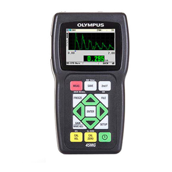
45MG
Ultrasonic Thickness Gage
User's Manual
This instruction manual contains essential information on how to use this Olympus product safely and effectively.
Before using this product, thoroughly review this instruction manual. Use the product as instructed.
Keep this instruction manual in a safe, accessible location.
DMTA-10022-01EN — Rev. C
January 2015
Advertisement
Chapters
Table of Contents
Troubleshooting

Related Manuals for Olympus 45MG


Summary of Contents for Olympus 45MG
- Page 1 DMTA-10022-01EN — Rev. C January 2015 This instruction manual contains essential information on how to use this Olympus product safely and effectively. Before using this product, thoroughly review this instruction manual. Use the product as instructed. Keep this instruction manual in a safe, accessible location.
- Page 2 Olympus Scientific Solutions Americas, 48 Woerd Avenue, Waltham, MA 02453, Copyright © 2012, 2013, 2015 by Olympus. All rights reserved. No part of this publication may be reproduced, translated, or distributed without the express written permission of Olympus. This document was prepared with particular attention to usage to ensure the accuracy of the information contained therein, and corresponds to the version of the product manufactured prior to the date appearing on the title page.
-
Page 3: Table Of Contents
DMTA-10022-01EN, Rev. C, January 2015 Table of Contents List of Abbreviations ..................ix Labels and Symbols ................... 1 Important Information — Please Read Before Use ........5 Intended Use .......................... 5 Instruction Manual ........................ 5 Instrument Compatibility ..................... 6 Repair and Modification ....................... 7 Safety Symbols ........................ - Page 4 DMTA-10022-01EN, Rev. C, January 2015 Environmental Ratings ..................... 19 Instrument Hardware Components ............... 19 Connectors ......................... 20 Keypad Functions ..................... 22 2. Powering the 45MG ................... 27 Power Indicator ......................27 Battery Power ......................28 2.2.1 Battery Operating Time ................. 28 2.2.2...
- Page 5 DMTA-10022-01EN, Rev. C, January 2015 Saving Data ........................ 65 6. Software Options ..................67 Activating Software Options ................... 68 Echo Detection Modes with Dual Element Transducers ........70 6.2.1 Blanking Adjustments in Manual Echo-to-Echo Detection Mode ..73 6.2.2 Dual Element Transducer Selection in Echo-to-Echo Modes ....74 Measurements with Optional THRU-COAT, D7906, and D7908 Transducers 76 6.3.1 Enabling the THRU-COAT Function ............
- Page 6 DMTA-10022-01EN, Rev. C, January 2015 6.7.5 Setting the ID Overwrite Protection ............115 6.7.6 ID Review Screen ..................115 6.7.6.1 Reviewing Stored Data and Changing the Active ID ....117 6.7.6.2 Editing the ID ..................117 6.7.6.3 Erasing Data in the Active File ............119 6.7.7 Generating Reports ..................
- Page 7 11.4.2 Sending a Screen Capture to the External microSD Card ...... 195 11.5 Resetting the Communication Parameters ............196 12. Maintaining and Troubleshooting the 45MG ........199 12.1 Routine Gage Handling ..................199 12.2 Cleaning the Instrument ..................200 12.3 Maintaining Transducers ..................200 12.4 Using Instrument Resets ..................
-
Page 8: Dmta-10022-01En, Rev. C, January
DMTA-10022-01EN, Rev. C, January 2015 List of Tables ....................227 Index ......................... 229 viii Table of Contents... -
Page 9: List Of Abbreviations
DMTA-10022-01EN, Rev. C, January 2015 List of Abbreviations two-dimensional AEtoE automatic Echo-to-Echo automatic gain control comma separated variables database DIAG diagnostic DIFF differential EFUP environment-friendly use period electronic stress screening extended fiber-reinforced polymer gigabytes green HDPE high-density polyethylene high identification LDPE low-density polyethylene loss-of-signal... - Page 10 DMTA-10022-01EN, Rev. C, January 2015 portable document format pulse repetition frequency polyvinyl chloride RoHS restriction of hazardous substances single element standard software time-dependent gain thin-film transistor (liquid crystal display technology) time-of-flight universal serial bus WEEE waste electrical and electronics equipment yellow List of Abbreviations...
-
Page 11: Labels And Symbols
T/R 2 connectors. Up to 200 V can be present on the inner conductor. The warning symbol between the Transmit/Receive (T/R) connector markings warns of this electric shock risk. Warning symbol USB symbol Figure i-1 The symbols on the top of the 45MG Labels and Symbols... -
Page 12: Figure I-2 Labels Attached To The Back Of The Instrument
DMTA-10022-01EN, Rev. C, January 2015 Instruction label Serial number labels (see Table 1 on page 3) (two locations) Figure i-2 Labels attached to the back of the instrument Labels and Symbols... -
Page 13: Table 1 Label Contents
DMTA-10022-01EN, Rev. C, January 2015 Table 1 Label contents Serial number yynnnnnmm label Where: yy: last two digits of the production year nnnnn: five-digit non-duplicated incrementing number representing the n production unit of this product mm: production month Instruction label Labels and Symbols... - Page 14 Seller and user shall be noticed that this equipment is suitable for electromagnetic equipment for office work (class A) and it can be used outside home. The MSIP code for the 45MG is the following: MSIP-REM-OYN-45MG. The regulatory compliance mark (RCM) label indicates that...
-
Page 15: Important Information - Please Read Before Use
The 45MG instrument is designed to measure thicknesses of industrial and commercial materials. WARNING Do not use the 45MG for any purpose other than its intended use. It must never be used to inspect or examine human or animal body parts. Instruction Manual This instruction manual contains essential information on how to use this Olympus product safely and effectively. -
Page 16: Instrument Compatibility
The 45MG documents are: 45MG Ultrasonic Thickness Gage — Getting Started (P/N: DMTA-10024-01EN [U8778520]) A short leaflet containing essential information for quick start-up of the 45MG instrument. 45MG Ultrasonic Thickness Gage — User’s Manual (P/N: DMTA-10022-01EN) This document is in PDF format, and contains a detailed description of the instrument, in addition to the setup and operating procedures for all the instrument features. -
Page 17: Repair And Modification
DMTA-10022-01EN, Rev. C, January 2015 Repair and Modification Apart from the batteries, the 45MG instrument does not contain any user-serviceable parts. CAUTION In order to prevent human injury and/or equipment damage, do not disassemble, modify, or attempt to repair the instrument. -
Page 18: Safety Signal Words
DMTA-10022-01EN, Rev. C, January 2015 Safety Signal Words The following safety symbols might appear in the documentation of the instrument: DANGER The DANGER signal word indicates an imminently hazardous situation. It calls attention to a procedure, practice, or the like, which, if not correctly performed or adhered to, will result in death or serious personal injury. -
Page 19: Safety
DMTA-10022-01EN, Rev. C, January 2015 NOTE The NOTE signal word calls attention to an operating procedure, practice, or the like, which requires special attention. A note also denotes related parenthetical information that is useful, but not imperative. The TIP signal word calls attention to a type of note that helps you apply the techniques and procedures described in the manual to your specific needs, or provides hints on how to effectively use the capabilities of the product. -
Page 20: Battery Precautions
For any problem or question regarding this instrument, contact Olympus or an authorized Olympus representative. • Do not touch the connectors directly by hand. Otherwise, a malfunction or electric shock may result. -
Page 21: Equipment Disposal
• Do not leave batteries in the 45MG unit during instrument storage. Equipment Disposal Before disposing of the 45MG, check your local laws, rules, and regulations, and follow them accordingly. WEEE Directive In accordance with European Directive 2012/19/EU on Waste Electrical... -
Page 22: Emc Directive Compliance
This equipment generates and uses radio-frequency energy and, if not installed and used properly (that is, in strict accordance with the manufacturer’s instructions), may cause interference. The 45MG has been tested and found to comply with the limits for an industrial device in accordance with the specifications of the EMC directive. -
Page 23: Regulatory Information
DMTA-10022-01EN, Rev. C, January 2015 Regulatory Information The 45MG may display a regulatory screen that lists the specific regulation with which it complies. To view the REGULATORY screen In the measurement screen, press [SETUP], and then select SP MENU. In the SP MENU (see Figure 4-2 on page 45), select REGULATORY to display the REGULATORY screen (see Figure i-3 on page 13). -
Page 24: Technical Support
Retain packing materials, waybills, and other shipping documentation needed in order to file a damage claim. After notifying the carrier, contact Olympus for assistance with the damage claim and equipment replacement, if necessary. -
Page 25: Introduction
DMTA-10022-01EN, Rev. C, January 2015 Introduction This user’s manual provides operating instruction for the 45MG ultrasonic thickness gage. The information in this manual is organized to explain the technology, safety details, hardware, and software. Practical measurement examples help the user become familiar with the instrument’s capabilities. - Page 26 DMTA-10022-01EN, Rev. C, January 2015 Introduction...
-
Page 27: Instrument Description
An optional advanced internal datalogger can store up to 475000 thickness measurements and 20000 waveforms. With the Single Element option, the 45MG operates with a full line of single element transducers. Operation with dual element transducers is a standard feature. -
Page 28: Dmta-10022-01En, Rev. C, January
DMTA-10022-01EN, Rev. C, January 2015 • Automatic probe recognition for the standard D79X and MTD705 series transducers • Warning against calibration doubling (for dual element transducers) • Calibration for unknown material sound velocity and/or transducer zero • Fast scan mode with 20 readings per second •... -
Page 29: Environmental Ratings
— Erase selected data or all stored data — Standard USB directional communication Environmental Ratings The 45MG is a rugged and durable instrument that can be used in harsh environments. The 45MG was designed to meet the requirement of the IP67 rating (Ingress Protection rating). -
Page 30: Connectors
Keypad Stand Power key Figure 1-1 The 45MG hardware components — Front, top, and side views Connectors Figure 1-2 on page 20 illustrates the possible connections between the 45MG and external devices. Transducer USB connector microSD memory card... -
Page 31: Figure 1-3 The Top End Connectors
DMTA-10022-01EN, Rev. C, January 2015 The USB and Transmit/Receive transducer connectors are located on the top of the 45MG (see Figure 1-3 on page 21). Transmit/Receive transducer connector 2 Transmit/Receive USB communication transducer connector 1 connector Figure 1-3 The top end connectors The external microSD memory card slot is located behind the battery door (see Figure 1-4 on page 21). -
Page 32: Keypad Functions
The yellow keys are related to calibration. Table 2 on page 23 lists the key functions available on the 45MG keypad. Many functions are optional, and may not be available depending on which software options have been purchased. -
Page 33: Table 2 Keypad Functions
DMTA-10022-01EN, Rev. C, January 2015 Table 2 Keypad functions English International Functions Measurement — Completes the current operation and returns to the measurement screen. Identification number — Accesses several functions related to the ID numbers for the thickness-measurement location. File — Opens the file menu to access file commands (open, review, create, copy, edit, delete, send, import, export, memory, and report). - Page 34 DMTA-10022-01EN, Rev. C, January 2015 Table 2 Keypad functions (continued) English International Functions Down arrow • In a screen or a list, moves to the next element. • For some parameters, a numerical entry decreases the value. Left arrow • Selects the previous available value for the selected parameter.
- Page 35 DMTA-10022-01EN, Rev. C, January 2015 Table 2 Keypad functions (continued) English International Functions Zero calibration • Compensates for transducer zero, or enables the step block zero calibration. • With the traditional text edit mode only, inserts a character at the cursor position. Do ZERO —...
- Page 36 DMTA-10022-01EN, Rev. C, January 2015 Chapter 1...
-
Page 37: Powering The 45Mg
The power indicator is always present on the left side of the screen, and it shows the type of power source used. The 45MG can be powered by three AA-size batteries, by a computer through its USB connector, or by a commercially available 5-volt USB power supply. -
Page 38: Battery Power
The battery operating time depends on the type of batteries being used, the age of the batteries, and the instrument settings. To provide realistic battery operating times, the 45MG has been tested with mid-level operating parameters (update rate set to 4 Hz and display brightness set to 20 %). -
Page 39: Battery Level And Storage
Avoid long-term storage under sunlight, or in other excessively hot places such as the trunk of an automobile. 2.2.3 Replacing the Batteries The batteries are located in a compartment that is accessible from the back of the 45MG (see Figure 2-3 on page 29). Batteries Battery compartment door Battery compartment... - Page 40 Do not disassemble, heat above 50 °C, or incinerate the batteries. To replace the batteries Ensure that the power to the 45MG is turned off. Disconnect any other cables connected to the 45MG. Remove the optional protective rubber boot, if installed.
-
Page 41: Figure 2-4 Selecting The Battery Type
DMTA-10022-01EN, Rev. C, January 2015 Figure 2-4 Selecting the battery type NOTE When replacing batteries, make sure that they are full in order to ensure the accuracy of the estimated remaining battery life shown by the power indicator. Powering the 45MG... - Page 42 DMTA-10022-01EN, Rev. C, January 2015 Chapter 2...
-
Page 43: Software User Interface Elements
DMTA-10022-01EN, Rev. C, January 2015 3. Software User Interface Elements The following sections describe the main elements of the 45MG software screens and menus. Measurement Screen The 45MG has two different main measurement screens: The first screen (see Figure 3-1 on page 33) displays when the Waveform option is not activated, or when the Waveform option feature is turned off. -
Page 44: Figure 3-2 The Measurement Screen - Waveform Option Enabled
The measurement screen is the main screen of the 45MG software. From anywhere in the 45MG software, simply press [MEAS] to return to the measurement screen. The power indicator is always present on the left side of the 45MG screen (see “Power Indicator” on page 27 for details). -
Page 45: Figure 3-4 Other Elements - No Waveform Option Enabled
(see Figure 1-4 on page 21). The 45MG will recognize an external microSD memory card, with a maximum capacity of 2 GB, upon instrument start-up. -
Page 46: Figure 3-5 Other Elements - Waveform Option Enabled
Alarm indicator Gain Figure 3-5 Other elements — Waveform option enabled The loss of signal (LOS) appears and the thickness value is cleared when the 45MG no longer detects ultrasonic echoes (see Figure 3-6 on page 36). No thickness value found... -
Page 47: Menus And Submenus
DMTA-10022-01EN, Rev. C, January 2015 Menus and Submenus The 45MG displays menus and submenus when you press certain front panel keys. The menu appears at the top-left corner of the screen (see Figure 3-7 on page 37). If applicable, a submenu conveniently showing the parameters available for the highlighted menu command also appears. -
Page 48: Parameter Screens
DMTA-10022-01EN, Rev. C, January 2015 Parameter Screens The 45MG parameters are logically grouped in parameter screens that can be accessed using front panel keys or menu commands. Figure 3-8 on page 38 shows the MEAS parameter screen as an example. -
Page 49: Selecting The Text Edit Mode
“In the MEAS screen, set MEAS MODE to THICKNESS.” Selecting the Text Edit Mode The 45MG offers two methods of editing the value of alphanumeric parameters. Either the virtual keyboard or traditional method can be used. The virtual keyboard appears on the screen to display all the available characters that can be used (see “Editing Text Parameters Using the Virtual Keyboard”... -
Page 50: Figure 3-9 Example Of The Virtual Keyboard
DMTA-10022-01EN, Rev. C, January 2015 Title bar Parameter value text Virtual keyboard Help text bars Figure 3-9 Example of the virtual keyboard To edit an alphanumeric parameter value using the virtual keyboard Select an alphanumeric parameter. The virtual keyboard appears. Use the [], [], [], and [] keys to highlight the character that you wish to enter, and then press [ENTER]. -
Page 51: Editing Text Parameters Using The Traditional Method
DMTA-10022-01EN, Rev. C, January 2015 To complete editing of the parameter value, highlight DONE on the virtual keyboard, and then press [ENTER]. NOTE When editing a multiple line parameter value, highlight DONE and press [ENTER] to move the cursor to the next line. You can also press [2nd F], [] to accept the text and move the cursor to the next line. - Page 52 DMTA-10022-01EN, Rev. C, January 2015 Use the [] and [] keys to select the character you want to enter. Hold down the key to quickly cycle through the letters, numbers, and special characters. Use the [] keys to move to the next character. Repeat step 2 and step 3 to enter other characters.
-
Page 53: Initial Setup
Norwegian, Portuguese, or Czech. You can also set the character delimiting the radix of a number. The 45MG includes a beep tone generator that confirms when a key is pressed and notifies you of an alarm condition. The beeper can be set to On or Off. -
Page 54: Selecting The Measurement Units
Press [MEAS] to return to the measurement screen. Setting the Clock The 45MG has a built-in date and time clock. You can set the date and the time and select their format. The 45MG saves all measurement values with their acquisition date. -
Page 55: Changing Display Settings
DMTA-10022-01EN, Rev. C, January 2015 Figure 4-2 The SP MENU screen In the CLOCK screen (see Figure 4-3 on page 45), set the parameters to the current date and time. Set the desired DATE MODE and HOUR MODE, and then select SET. Figure 4-3 The CLOCK screen Changing Display Settings The appearance of certain display elements, such as colors, brightness, waveform... -
Page 56: Figure 4-4 The Display Screen
DMTA-10022-01EN, Rev. C, January 2015 To change the display settings In the measurement screen, press [SETUP], and then select DISPLAY. NOTE Many of the display parameters are only visible when the Waveform or Datalogger options have been activated. In the DISPLAY screen (see Figure 4-4 on page 46), select the desired parameter and value for the following parameters: •... -
Page 57: Color Schemes
Press [MEAS] to return to the measurement screen. 4.4.1 Color Schemes The 45MG offers two standard color schemes designed to provide the best display visibility in indoor or outdoor lighting conditions (see Figure 4-5 on page 47). To set the color scheme In the measurement screen, press [SETUP], and then select DISPLAY. -
Page 58: Display Brightness
4.4.2 Display Brightness The 45MG display brightness can be adjusted by selecting the backlight intensity. The display brightness can be set in 5 % increments from 0 % to 100 %. Choosing a high percentage increases the brightness of the display. By default, the display brightness is set to 20 %. -
Page 59: Figure 4-6 The Measurement Update Rate Indicator
NOTE The 45MG automatically uses the fastest update rate when put into the Minimum or Maximum mode (see “Using the Minimum, Maximum, or Min/Max Thickness Mode” on page 129). -
Page 60: Changing The Thickness Resolution
The Single Element including High Resolution software option (P/N: 45MG-SE [U8147022]) makes it possible to increase the resolution to 0.001 mm (or 0.0001 in.). -
Page 61: Basic Operation
The following sections describe the basic operation for the 45MG ultrasonic thickness gage. Setting Up the Transducer The 45MG operates with a full line of single element (optional software) and dual element transducers. The 45MG automatically recognizes standard D79X dual element transducers, and automatically loads the appropriate predefined setup. The predefined setup contains ultrasonic velocity for the stainless steel step block supplied with the instrument. -
Page 62: Figure 5-1 Plugging In The Transducer
DMTA-10022-01EN, Rev. C, January 2015 Standard dual element transducer connector T/R 1 connector for a single element transducer Figure 5-1 Plugging in the transducer Press to start the instrument. The measurement screen appears. With a standard D79X dual element transducer, the “Do--” message appears in the measurement screen (see Figure 5-2 on page 52). -
Page 63: Figure 5-3 Selecting A Default Single Element Transducer Setup
DMTA-10022-01EN, Rev. C, January 2015 For the Single Element software option and a single element transducer, load an appropriate setup: a) Press [2nd F], [FREEZE] (XDCR RECALL). b) In the menu, select the default choice for the probe type that you use (ex.: DEFAULT SINGLE ELEMENT). -
Page 64: Calibration
DMTA-10022-01EN, Rev. C, January 2015 d) Press [MEAS] to automatically recall the setup parameters for the chosen setup and return to the measurement screen. Calibration Calibration is the process of adjusting the instrument to perform accurate measurements on a particular material at a given temperature using a known transducer. -
Page 65: Calibrating The Instrument
DMTA-10022-01EN, Rev. C, January 2015 5.2.1 Calibrating the Instrument To make accurate measurements, you need to perform the following calibrations: • Material sound velocity calibration • Zero calibration The calibrations must be performed using a thick and a thin sample of precisely known thicknesses. -
Page 66: Figure 5-5 Performing The Sound Velocity Calibration On A Five-Step Test Block
DMTA-10022-01EN, Rev. C, January 2015 With Waveform option Without Waveform option Figure 5-5 Performing the sound velocity calibration on a five-step test block To perform the zero calibration using an instrument with or without the Waveform option (see Figure 5-7 on page 57): a) Place a drop of couplant on the surface of the thin part of the test block. -
Page 67: Figure 5-7 Performing The Zero Calibration On A Five-Step Test Block
Instead, the instrument retains the previous value. NOTE When the 45MG detects an error in the calibration procedure, it successively displays the following messages in the help text bar before returning to the measurement screen: “Potential wrong echo detected!”... -
Page 68: Test Blocks
DMTA-10022-01EN, Rev. C, January 2015 5.2.2 Test Blocks The 45MG comes with a cylindrical stainless steel test block with two thicknesses. Two precisely known test-block thicknesses can be used to perform the material sound velocity and the zero calibrations. Precision step test blocks are also often used when more than two known thicknesses are needed (see Figure 5-8 on page 58). -
Page 69: Material Sound Velocity And The Zero Calibrations
The 45MG compares the measured time of flight to the expected time of flight based on the current sound velocity. The 45MG displays a warning message if doubling is suspected. -
Page 70: Entering A Known Material Sound Velocity
5.2.6 Locked Calibrations The 45MG includes a password-protected locking function to prevent changes to setups, and prevent access to certain functions. A change to the calibration is one action that can be locked. In such case, the message shown in Figure 5-10 on page 61 appears momentarily on the help text bar (see “Locking the Instrument”... -
Page 71: Factors Affecting Performance And Accuracy
Calibration The accuracy of any ultrasonic measurement is only as good as the accuracy and care with which you calibrate the instrument. The 45MG ships from the factory with standard setups for a number of transducers and applications. In certain cases, it may be desirable to optimize these setups for specific measurement situations. - Page 72 DMTA-10022-01EN, Rev. C, January 2015 couplant than larger-diameter transducers. In all modes, tilting the transducer distorts echoes, and causes inaccurate readings, as noted below. Curvature of the test piece A related issue involves the alignment of the transducer with respect to the test piece.
-
Page 73: Measuring Thicknesses
Phase reversal or phase distortion The phase or polarity of a returning echo is determined by the relative acoustic impedances (density × velocity) of the boundary materials. The 45MG performs computation based on the customary situation, where the test piece is backed by air or a liquid, both of which have a lower acoustic impedance than metals, ceramics, or plastics. -
Page 74: Figure 5-11 Coupling A Dual Element Transducer
DMTA-10022-01EN, Rev. C, January 2015 NOTE In general, use a thinner couplant (such as propylene glycol, glycerin, or water) for smooth material surfaces. Rough surfaces require a more viscous couplant, such as gel or grease. Special couplants are required for high-temperature applications. Using moderate to firm pressure, couple the tip of the transducer to the surface of the test material, and keep the transducer as flat as possible on the material surface (see Figure 5-11 on page 64). -
Page 75: Saving Data
Figure 5-12 Reading the measured thickness Saving Data The 45MG optional datalogger is a file-based system, in which one file is opened at a time. The active file stores a measurement at a thickness-measurement location ID. Each time you press [SAVE], the displayed value is saved to the active file at the current ID. - Page 76 The NONAME00 increment-type file, starting with the 001 ID, is the active file by default when you first use the 45MG, or after resetting the instrument memory. Various types of files can be created, and IDs can be defined to represent various 1-D, 2-D, or 3-D thickness-measurement locations.
-
Page 77: Software Options
DMTA-10022-01EN, Rev. C, January 2015 6. Software Options The available software options can be used to increase the capability of the already versatile 45MG (see Table 3 on page 67). Table 3 45MG software options Part Option Description number Echo-to-Echo &... -
Page 78: Activating Software Options
Refer to Table 3 on page 67 for the software-option part numbers. Activating Software Options Each 45MG has a unique serial number code. A provided option key specific to a particular 45MG activates the purchased software options only on that specific 45MG unit. -
Page 79: Figure 6-1 The Options Screen
Option key text box Figure 6-1 The OPTIONS screen To purchase one or more software options, contact your local Olympus representative and provide the alphanumeric serial number (E-S/N). Your Olympus representative will provide you with the corresponding option key. -
Page 80: Echo Detection Modes With Dual Element Transducers
DMTA-10022-01EN, Rev. C, January 2015 Echo Detection Modes with Dual Element Transducers With dual element transducers, the 45MG offers three echo detection modes that allow you to measure thicknesses in various material conditions. A description of each of the three echo detection modes (STANDARD, optional AUTO E-TO-E, and... -
Page 81: Figure 6-3 Measuring With The Automatic Echo-To-Echo Detection Mode
DMTA-10022-01EN, Rev. C, January 2015 by an Echo-to-Echo detection bar that indicates the exact pair of back-wall echoes used to determine the thickness (see Figure 6-3 on page 71). The echo height is automatically adjusted to a preset level. Dual element (DE) automatic Echo-to-Echo (AEtoE) Echo-to-echo detection mode detection bar... -
Page 82: Figure 6-4 Measuring With The Manual Echo-To-Echo Detection Mode
DMTA-10022-01EN, Rev. C, January 2015 E1 blank bar [WAVE ADJ] parameter Echo-to-Echo detection Dual element (DE) manual Echo-to-Echo (MEtoE) detection mode Figure 6-4 Measuring with the manual Echo-to-Echo detection mode NOTE In severe corrosion situations where valid multiple echoes are not present, you must use either the standard or optional THRU-COAT mode in order to be able to measure thicknesses. -
Page 83: Blanking Adjustments In Manual Echo-To-Echo Detection Mode
6.2.1 Blanking Adjustments in Manual Echo-to-Echo Detection Mode The 45MG offers two blanking functions to help detect valid echoes in situations where material conditions generate unwanted signals: EXT BLANK The extended blank creates a blanked zone that begins at the left edge of the waveform display, and in which no signals are detected. -
Page 84: Dual Element Transducer Selection In Echo-To-Echo Modes
6.2.2 Dual Element Transducer Selection in Echo-to-Echo Modes Although the optional Echo-to-Echo modes work with all the 45MG dual element transducers, Olympus recommends using specific transducers for particular thickness ranges in steel parts (see Table 4 on page 75). -
Page 85: Table 4 Recommended Transducers For Various Steel Thickness Ranges
Echo-to-Echo detection mode, or by moving the extended blank beyond the previously detected first echo. When the 45MG cannot make an echo-to-echo reading, the LOS flag appears on the screen. In this case, the waveform display shows that either no echoes are large enough to be detected, or that only one echo is detectable. -
Page 86: Measurements With Optional Thru-Coat, D7906, And D7908 Transducers
6.3.1 Enabling the THRU-COAT Function The THRU-COAT function is only available when you connect a THRU-COAT transducer (P/N: D7906 [U8450005] or D7908 [U8450008]) to the 45MG. To enable the THRU-COAT function Connect a THRU-COAT transducer to the 45MG. Turn on the instrument. -
Page 87: Performing A Thru-Coat Calibration
DMTA-10022-01EN, Rev. C, January 2015 Figure 6-6 Opening the THRU-COAT setup dialog box Select YES to answer the Enable THRU COAT? prompt. 6.3.2 Performing a THRU-COAT Calibration The calibration procedure for a THRU-COAT probe is similar to the procedure for other probes. -
Page 88: Waveform Software Option
Waveform Software Option The live Waveform option for the 45MG allows the user to view the live ultrasonic waveform in order to aid alignment of the transducer during difficult applications. When this option is activated, the user can switch between the standard thickness display (see Figure 6-7 on page 79) and the optional waveform thickness display (see Figure 6-8 on page 80). -
Page 89: Figure 6-7 Standard Display
DMTA-10022-01EN, Rev. C, January 2015 • Adjust the waveform range and delay. — With the Single Element transducer option (see “Custom Setups for Single Element Transducers” on page 165): • Adjust the pulse-receive parameters (TVG gain and blanks) • Create custom single element transducer setups. •... -
Page 90: Waveform Rectification
DMTA-10022-01EN, Rev. C, January 2015 Figure 6-8 Waveform display To activate the waveform In the measurement screen, press [SETUP], and then select DISPLAY. Set WAVEFORM ENABLE to ON. 6.4.1 Waveform Rectification The rectification mode determines the way in which the ultrasonic echoes are represented on the waveform display (see Figure 6-9 on page 81). -
Page 91: Figure 6-9 Examples Of The Rectification Modes
DMTA-10022-01EN, Rev. C, January 2015 Full Half− Half+ Figure 6-9 Examples of the rectification modes The available rectification modes are: FULL This mode shows the negative portion of the echo folded around the baseline, so that both positive and negative waveform lobes are displayed. This mode provides the best overall representation of position and magnitude for most thickness-measurement applications. -
Page 92: Waveform Trace
6.4.2 Waveform Trace The 45MG can display the waveform trace as a line (OUTLINE), or as a FILLED area (see Figure 6-10 on page 82). In the measurement screen, press [SETUP], and then select DISPLAY to access the WAVEFORM TRACE parameter. -
Page 93: Selecting The Range Value
DMTA-10022-01EN, Rev. C, January 2015 Selectable range value Adjustable delay value Units Figure 6-11 The range of the waveform display 6.4.3.1 Selecting the Range Value There are fixed ranges available for each transducer frequency. The available ranges are also dependent on material sound velocity. These selectable ranges let you adjust the thickness span of the waveform display to show only the thickness range being measured, and thus obtain maximum waveform resolution for each application. -
Page 94: Adjusting The Delay Value
DMTA-10022-01EN, Rev. C, January 2015 NOTE When the [GAIN/WAVE ADJ] parameters are active, the range and delay become items in the parameter list. Use the [] and [] keys to highlight the range parameter, and the [] and [] keys to adjust the range. Press [MEAS] to stop adjusting the range. -
Page 95: Figure 6-12 Comparing The Normal And Zoomed Display In Mode 1
DMTA-10022-01EN, Rev. C, January 2015 The resulting zoomed waveform depends on the current measurement mode. The zoom for D79X dual element transducers and mode 1 single element transducers centers the first back-wall echo on the screen (see Figure 6-12 on page 85). Normal display Zoomed display Figure 6-12 Comparing the normal and zoomed display in mode 1... -
Page 96: Single Element And High Resolution Option
In the DISPLAY screen, set the ZOOM OPTION to OFF. Single Element and High Resolution Option The optional Single Element High Resolution software allows the 45MG to use single element direct contact, delay line, and immersion transducers. This enables the 45MG to be used for precision thickness gaging applications. -
Page 97: Recalling Single Element Transducer Setups
0.001 mm (or 0.0001 in.). High resolution is not available for all transducers and measurement modes, and is also limited to the maximum thickness. Although the 45MG is able to display thickness readings in high resolution, the measurement accuracy is highly dependent on the material, geometry, surface condition, and temperature, and also needs to be determined on a case-by-case sample evaluation basis. -
Page 98: High-Penetration Software Option
Ensure that the high-penetration software option is activated (see “Activating Software Options” on page 68 for details). Connect the M2008 transducer to the T/R 1 connector at the top of the 45MG. Press [2nd F], [FREEZE] (XDCR RECALL). In the menu, select DEFAULT HP SINGLE ELEMENT. -
Page 99: Datalogger
6.7.1 Datalogger The 45MG datalogger is a file-based system, in which one file is opened at a time. The active file stores a measurement at a thickness-measurement location ID. Each time you press [SAVE], the displayed value is saved to the active file at the current ID. The ID is automatically incremented for the next measurement. -
Page 100: Figure 6-16 Identifying Datalogger Parameters
Previous thickness ID number Figure 6-16 Identifying datalogger parameters With each measurement, the 45MG also stores a complete description of the measurement conditions. Table 6 on page 91 describes the additional data stored with each thickness measurement and with each waveform. -
Page 101: Table 6 Additional Information Stored With The Data
20000 thickness values with waveforms. You can double the storage capacity by using an optional external microSD memory card. The maximum capacity of the external microSD card that can be used on the 45MG is 2 GB. -
Page 102: Creating A Data File
The following procedure describes how to create a data file in the 45MG. NOTE It is also possible to create a 45MG data file from a computer using the GageView interface program. Refer to the GageView Interface Program — User’s Manual (P/N: 910-259-EN [U8778347]) for details. -
Page 103: Data File Types
DMTA-10022-01EN, Rev. C, January 2015 • 2D GRID see “2-D Grid Data File Type” on page 98 • BOILER see “Boiler Data File Type” on page 102 Figure 6-17 Example of the CREATE screen At any time, you can press [2nd F], [] or [2nd F], [] to scroll between parameters on the screen. -
Page 104: Incremental Data File Type
DMTA-10022-01EN, Rev. C, January 2015 6.7.2.2 Incremental Data File Type The incremental data file type uses the alphanumeric start ID value (up to 20 characters), and automatically increments to the subsequent ID value using the following incrementation rules: • Increments only digits and letters, not punctuation marks or other special characters. -
Page 105: Figure 6-18 The Create Screen For The Incremental Data File Type
DMTA-10022-01EN, Rev. C, January 2015 Table 7 Resulting ID examples for the INCREMENTAL file type (continued) START ID Resulting IDs ..ABC*12*34 ABC*12*34 ABC*12*35 ABC*12*36 ABC*12*99 To create an incremental data file In the measurement screen, press [FILE], and then select CREATE (see “Creating a Data File”... -
Page 106: Sequential Data File Type
DMTA-10022-01EN, Rev. C, January 2015 6.7.2.3 Sequential Data File Type The sequential data file type is similar to the incremental type, although it also allows you to define both starting and ending ID numbers. The resulting file is inclusive of the starting and ending points, and all incremental points in between (see the examples in Table 8 on page 96). -
Page 107: Sequential With Custom Point Data File Type
DMTA-10022-01EN, Rev. C, January 2015 Figure 6-19 Selecting the ID range for the sequential file type 6.7.2.4 Sequential with Custom Point Data File Type The sequential with custom point (SEQ+CUSTOM PT) data file type is defined by a starting and an ending ID number, plus a series of custom points. The resulting file is inclusive of the start and end points, and all points in between. -
Page 108: 2-D Grid Data File Type
DMTA-10022-01EN, Rev. C, January 2015 The allowable number of characters for each custom point depends on the number of ID characters defined in the start and end ID values. The total number of characters of the ID value plus the custom points cannot exceed 20. For example, when the start and end ID values are seven characters long, as shown in the example in Table 9 on page 97, the maximum allowable length for each custom point is thirteen (20 −... -
Page 109: Figure 6-21 General 2-D Grid Example
DMTA-10022-01EN, Rev. C, January 2015 A 2-D (two-dimensional) sequence begins with the ID number that refers to the first column and the first row (see Figure 6-21 on page 99). The column (or row) then increments one value at a time until the sequence reaches the last column (or row) value, while the other dimension value stays constant. -
Page 110: Figure 6-22 One Grid For 75 Identical Parts
DMTA-10022-01EN, Rev. C, January 2015 Measurement location Column Figure 6-22 One grid for 75 identical parts Alternatively, the rows and columns of a grid may refer to a two-dimensional map of measurement points on the surface of one part. In this case, a different grid is created for each part (see the examples in Figure 6-23 on page 101). -
Page 111: Figure 6-23 Differently Named Grid For Each Part
DMTA-10022-01EN, Rev. C, January 2015 Name: Elbow Rows: 01 through 10 Columns: A through E IDs: Elbow/A0 through Elbow/E10 Name: Tee Rows: 1 through 4 Columns: 1 through 3 IDs: Tee/11 through Tee/34 Figure 6-23 Differently named grid for each part To create a 2-D grid data file In the measurement screen, press [FILE], and then select CREATE (see “Creating a Data File”... -
Page 112: Boiler Data File Type
Figure 6-24 Configuring the ID range for a 2-D grid data file type NOTE The 45MG has the capability to add a row or a column, and to change the incrementation direction after a grid file is created (see “Editing a File” on page 108 for details). -
Page 113: Table 10 Resulting Id Example For The Boiler File Type
DMTA-10022-01EN, Rev. C, January 2015 Tube number The second dimension refers to the number of the specific boiler tube to be inspected. Custom points The third dimension refers to the actual thickness reading location at the specified elevation on the specified tube. The three dimensions are combined in a single ID number to precisely identify the exact location of each thickness reading. -
Page 114: File Data Modes
6.7.3 File Data Modes When you create a data file on the 45MG, the file data mode must be selected in order to determine which measured values are stored in the file (see step 2.f in “Creating a Data File” on page 92). Table 11 on page 104 describes the available file data-mode options. -
Page 115: Performing File Operations
DMTA-10022-01EN, Rev. C, January 2015 Table 11 File data-mode stored measurements (continued) File data mode Stored measurements When to use MIN/MAX Minimum thickness When using the MIN/MAX mode Maximum thickness (see “Using the Minimum, Maximum, or Min/Max Thickness Mode” on page 129). TIME OF FLT Time of flight When measuring time of flight... -
Page 116: Opening A File
DMTA-10022-01EN, Rev. C, January 2015 Figure 6-26 The FILE menu 6.7.4.1 Opening a File You can open an existing file to make it the active file in which new measurements are saved. To open a file Press [FILE], and then select OPEN. In the OPEN screen (see Figure 6-27 on page 107): a) In SORT BY, select the order in which the files appearing on-screen are sorted (by NAME or by DATE CREATED). -
Page 117: Reviewing A File
DMTA-10022-01EN, Rev. C, January 2015 Figure 6-27 Opening a file 6.7.4.2 Reviewing a File There are two ways to review the contents of a file stored in the internal datalogger: by using OPEN or REVIEW in the FILE menu. To review a file using OPEN Press [FILE], and then select OPEN. -
Page 118: Editing A File
DMTA-10022-01EN, Rev. C, January 2015 The file copy function can only be used to copy an existing file in the internal memory to the internal memory. Use the file import and export functions to copy data to and from the internal memory and the external microSD card. To copy a file In the measurement screen, press [FILE], and then select COPY. - Page 119 DMTA-10022-01EN, Rev. C, January 2015 • Location note • Delete protection (on/off) • End row, column, or point of a grid file • Incrementing order of a grid file • Incrementing direction (forwards or reverse) for rows, columns, points, tube numbers, and elevations The edit function does not allow you to edit the file type, and cannot be used to edit individual measurement identifiers (ID), or actual thickness readings.
-
Page 120: Figure 6-29 Entering New File Information
DMTA-10022-01EN, Rev. C, January 2015 Figure 6-29 Entering new file information For a grid file, select CONTINUE, and then perform the following actions in the second page of the EDIT screen (see Figure 6-30 on page 111): a) Increase the END COLUMN and END ROW values as needed. These values cannot be decreased. -
Page 121: Deleting A File Or Its Contents
Once a file is deleted, it is not possible to recover any information previously contained in that file. To delete a file stored in the 45MG In the measurement screen, press [FILE], and then select DELETE. In the DELETE screen (see Figure 6-31 on page 112): a) Set DELETE ON to FILE in order to delete an entire file. -
Page 122: Deleting A Range Of Ids
Figure 6-31 Deleting a file NOTE If you select multiple files for deletion, and some of those files are delete-protected, the 45MG will only delete the files that are not delete-protected. 6.7.4.6 Deleting a Range of IDs It is possible to delete a range of IDs in the active file by using the clear memory function. -
Page 123: Deleting All Data Files
Figure 6-32 Deleting the data of an ID range in the active file 6.7.4.7 Deleting All Data Files The reset function can be used to quickly erase all the files stored in the 45MG. CAUTION Using the internal memory reset or master reset erases all files, and the data contained in those files. -
Page 124: Viewing The Memory Status
DMTA-10022-01EN, Rev. C, January 2015 b) Select RESET to delete all the files. Select CANCEL, or press [MEAS] to abort the operation. Figure 6-33 Warning message when resetting measurements 6.7.4.8 Viewing the Memory Status To view the memory status Press [FILE], select MEMORY, and then press [ENTER] to display the MEMORY status screen (see Figure 6-34 on page 114). -
Page 125: Setting The Id Overwrite Protection
DMTA-10022-01EN, Rev. C, January 2015 6.7.5 Setting the ID Overwrite Protection The ID overwrite protection can be activated to warn you every time you attempt to overwrite an existing measurement in a file. This function can be enabled at any time. When the ID overwrite protection is enabled, a message appears (see Figure 6-35 on page 115) on the help text bar when you perform a save to inform you that the existing thickness readings/waveforms will be overwritten. -
Page 126: Figure 6-36 Identifying The Id Review Screen
DMTA-10022-01EN, Rev. C, January 2015 Communications and Data Transfer” on page 187). Active ID m: Minimum value M: Maximum value m: MIN / MAX Gain when using a dual element transducer Dual element transducer: LOS: Loss-of-signal indicator DE-STD: Standard DE-AEtoE: Automatic Echo-to- Differential mode: Echo D:X.XXXIN: Normal... -
Page 127: Reviewing Stored Data And Changing The Active Id
DMTA-10022-01EN, Rev. C, January 2015 To review stored data and change the active ID Open the file you want to review (see “Opening a File” on page 106). In the measurement screen, press [2nd F], [FILE] (ID#). While in the ID review screen (see Figure 6-36 on page 116), perform the following actions: a) Review the waveform, status flags, and measured values for the active ID. -
Page 128: Figure 6-37 Editing The Id # Edit Mode
DMTA-10022-01EN, Rev. C, January 2015 Press [2nd F], [FILE] (ID#) again, and then edit the ID value (see Figure 6-37 on page 118). Figure 6-37 Editing the ID # edit mode Press [MEAS] to return to the measurement screen with the new active ID. When the edited ID is not in the database, the help text bar message shown in Figure 6-38 on page 119 appears. -
Page 129: Erasing Data In The Active File
DMTA-10022-01EN, Rev. C, January 2015 Press [SAVE] with or without an active measurement to make the edited ID a permanent part of the database. The sequence resumes at the previous active ID. 6.7.6.3 Erasing Data in the Active File CAUTION Data erased using the following techniques CANNOT be recovered. -
Page 130: Generating Reports
DMTA-10022-01EN, Rev. C, January 2015 6.7.7 Generating Reports The 45MG can generate inspection data reports without having to be connected to a computer or printer. The following reports are available: File summary Shows basic statistics for the file (minimum thickness and location, maximum thickness and location, and high and low alarm conditions along with the mean, median, and standard deviation). -
Page 131: Figure 6-39 The File Summary Report Screen
DMTA-10022-01EN, Rev. C, January 2015 b) Select REPORT. The FILE SUMMARY report result screen opens (see Figure 6-40 on page 122). Figure 6-39 The FILE SUMMARY report screen Figure 6-40 The FILE SUMMARY report result screen Select CANCEL to return to the measurement screen, or NEW REPORT to generate another report. -
Page 132: Figure 6-41 The Min/Max Summary Report Screen
DMTA-10022-01EN, Rev. C, January 2015 highlighted (see Figure 6-41 on page 122). Figure 6-41 The MIN/MAX SUMMARY report screen Press [2nd F], [] or [2nd F], [] to move between the #MINS and #MAXS lists. d) Select CANCEL to return to the measurement screen, or NEW REPORT to generate another report. -
Page 133: Figure 6-42 The File Comparison Report Screen
DMTA-10022-01EN, Rev. C, January 2015 Figure 6-42 The FILE COMPARISON report screen Figure 6-43 The FILE COMPARISON report result screen d) Review the maximum wall-loss location list, and the maximum wall growth location list. Select CANCEL to return to the measurement screen, or NEW REPORT to generate another report. -
Page 134: Figure 6-44 The Alarm Summary Report Result Screen
DMTA-10022-01EN, Rev. C, January 2015 Figure 6-44 The ALARM SUMMARY report result screen Review the low and the high alarm location lists. d) Select CANCEL to return to the measurement screen, or NEW REPORT to generate another report. In the MIN REVIEW screen: a) Select the file for which you want to generate the report. -
Page 135: Figure 6-46 Returning To The Measurement Screen
DMTA-10022-01EN, Rev. C, January 2015 In the list, select an ID. The 45MG returns to the live measurement screen at the selected minimum ID in the file (see Figure 6-46 on page 125). Figure 6-46 Returning to the measurement screen d) Couple the probe back to the minimum ID location to verify the thickness, and then press [SAVE] to store the new measurement. - Page 136 DMTA-10022-01EN, Rev. C, January 2015 Chapter 6...
-
Page 137: Using Special Functions
Activating and Configuring a Differential Mode The 45MG includes differential modes that can be used to easily compare the actual measurement with an entered reference value. The actual thickness measurement appears on the thickness display, and the differential value appears in the differential display area (see Figure 7-1 on page 127). - Page 138 When you press [SAVE] (with the optional datalogger) while in the NORMAL or % RATIO differential modes, the 45MG saves the actual thickness value along with the “D” flag indicating that the Differential mode is active. To activate and configure a differential mode In the measurement screen, press [SETUP], and then select DIFF.
-
Page 139: Using The Minimum, Maximum, Or Min/Max Thickness Mode
DMTA-10022-01EN, Rev. C, January 2015 Figure 7-2 The DIFF screen When DIFF MODE is set to REDUCTION RT only: d) In the FORMER THICKNESS text box, enter the original thickness value, as measured before bending the metal. In the LARGE FONT text box, select which measurement is to appear at the bottom of the measurement screen with the large type font (THICKNESS or REDUCTION RT). -
Page 140: Figure 7-3 Displaying The Minimum And/Or Maximum Thickness (Shown With The Waveform Option Activated)
DMTA-10022-01EN, Rev. C, January 2015 Active reading Active reading Minimum thickness Maximum thickness Recalled maximum during LOS Active reading Minimum and maximum Maximum thickness thicknesses Figure 7-3 Displaying the minimum and/or maximum thickness (shown with the Waveform option activated) NOTE The fastest display update rate is automatically activated when entering the minimum or maximum thickness mode. -
Page 141: Preventing False Minimum/Maximum Thickness Readings
Using Alarms Any one of the 45MG alarm modes can be activated to help you identify when the actual thickness measurement is above or below editable reference values. When an alarm condition occurs, the 45MG warns you, as follows:... -
Page 142: Figure 7-4 Example Of A High Alarm Indicator (Shown With The Waveform Option Activated)
• When the beeper is active (see “Setting the User Interface Language and Other System Options” on page 43), the 45MG emits a long beep. NOTE The thickness value and alarm indicator only appear in color when the indoor color scheme is active (see “Color Schemes”... -
Page 143: Figure 7-5 Example Of A B-Scan Alarm Mode
DMTA-10022-01EN, Rev. C, January 2015 There are three different alarm modes (STANDARD, B-SCAN, and REDUCTION RT): STANDARD The standard alarm warns you when the actual measured thickness is below a low reference value, or above a high reference value. The reference values are thickness set points using the current instrument units and resolution. -
Page 144: Figure 7-6 Yel (Yellow) And Red Alarm Indicators (Shown With The Waveform Option Activated)
DMTA-10022-01EN, Rev. C, January 2015 NOTE The thickness value and the alarm indicator only appear in color when the indoor color scheme is active (see “Color Schemes” on page 47 to change the color scheme). REDUCTION RT The REDUCTION RT option only appears when the active file is configured with FILE DATA MODE set to REDUCTION RT. -
Page 145: Figure 7-7 Setting Up The Standard Alarm
DMTA-10022-01EN, Rev. C, January 2015 In the ALARM screen (see Figure 7-7 on page 135): a) Set ALARM ENABLE to ON to activate the alarm function. b) In ALARM MODE, select the desired alarm mode (STANDARD, B-SCAN, or REDUCTION RT [reduction rate]). The other parameters vary depending on the alarm mode selection. -
Page 146: Locking The Instrument
Locking the Instrument The 45MG is equipped with an instrument lock that can be used by a supervisor to restrict access to selected functions. The supervisor can also enter a password to prevent other users from unlocking the functions. -
Page 147: Figure 7-8 Example Of A Locked Function Message In The Help Bar
DMTA-10022-01EN, Rev. C, January 2015 Figure 7-8 Example of a locked function message in the help bar To set the password In the measurement screen, press [SETUP], and then select PASSWORD. In the PASSWORD screen (see Figure 7-9 on page 137), enter your password using up to eight alphanumeric characters. -
Page 148: Freezing The Measurement Or Optional Waveform
DMTA-10022-01EN, Rev. C, January 2015 To lock and unlock instrument functions In the measurement screen, press [SETUP], and then select LOCKS. In the LOCKS screen (see Figure 7-10 on page 138): a) If a password was set, enter the password in the ENTER PASSWORD text box. - Page 149 DMTA-10022-01EN, Rev. C, January 2015 To freeze the waveform and thickness display Press [FREEZE] while making a measurement. Press [FREEZE] again to unfreeze the waveform and the thickness display. NOTE Pressing [MEAS] or [SAVE] (when the Datalogger option has been activated) also unfreezes the display.
- Page 150 DMTA-10022-01EN, Rev. C, January 2015 Chapter 7...
-
Page 151: Configuring The Instrument
DMTA-10022-01EN, Rev. C, January 2015 8. Configuring the Instrument This chapter describes how to configure the instrument’s measurement, system, and communication parameters. Configuring Measurement Parameters The MEAS setup is the most commonly used setup menu screen, and is used to access global parameters concerning the instrument measurement features. -
Page 152: Figure 8-1 The Meas Screen
DMTA-10022-01EN, Rev. C, January 2015 For a single element transducer For a dual element transducer Figure 8-1 The MEAS screen In the MEAS screen for single element transducers, in the MEAS MODE text box, select the instrument measures and displays from the following options: •... - Page 153 DMTA-10022-01EN, Rev. C, January 2015 Thickness Mode” on page 129 for details). In the HOLD BLANK text box, configure the instrument to either continue to show (HOLD), or not hold (BLANK) the last measured thickness and waveform while a loss of signal (LOS) occurs. NOTE The MIN/MAX and HOLD BLANK functions are mutually exclusive.
-
Page 154: Configuring System Parameters
DMTA-10022-01EN, Rev. C, January 2015 Configuring System Parameters The SYSTEM screen, allows you to configure many 45MG system parameters. To configure system parameters In the measurement screen, press [SETUP], and then select SYSTEM. The SYSTEM screen appears (see Figure 8-2 on page 144). -
Page 155: Configuring Communications
(TRADITIONAL) [see “Selecting the Text Edit Mode” on page 39 for details]. Set SCR TO SD CARD to ON to enable the 45MG to create a BMP image file on the external microSD card for the actual screenshot when you press [2nd F], [SETUP] (see “Sending a Screen Capture to the External microSD Card”... - Page 156 B-scan data. This parameter only applies to files that have stored B-scan images. d) Set FTP OUTPUT to 45MG in order to use the 45MG file protocol. Set FTP OUTPUT to 38DLP in order to use the 38DL PLUS file protocol.
-
Page 157: Figure 8-3 The Comm Screen
DMTA-10022-01EN, Rev. C, January 2015 Figure 8-3 The COMM screen Configuring the Instrument... - Page 158 DMTA-10022-01EN, Rev. C, January 2015 Chapter 8...
-
Page 159: Using Advanced Gaging Features
Adjusting the Gain with Dual Element Transducers With D79X series dual element transducers, you can manually adjust the gain by pressing [GAIN/WAVE ADJ]. The 45MG offers two types of gain adjustments: • The standard feature allows the user to set the gain to HIGH (+10 dB), standard (default), and LOW ( 6 dB). -
Page 160: Figure 9-1 Manually Adjusting The Gain
DMTA-10022-01EN, Rev. C, January 2015 Echo must be above the 20 % Manually adjusted gain detection threshold of the waveform value display height in order to be detected. Figure 9-1 Manually adjusting the gain When activated, the manual gain adjustment also modifies the way in which echoes are shown on the waveform display (optional). -
Page 161: Adjusting The Extended Blank With Dual Element Transducers
Incorrect use of the extended blank can cause the gage to misread areas of thin material. Normally, the 45MG searches for echoes down to nearly zero thickness. However, some special circumstances, such as a high degree of near-surface corrosion, aluminum material, enclosed flaws, or laminations, can generate echoes that the instrument may falsely detect as the low thickness. -
Page 162: Figure 9-2 Adjusting The Extended Blank Length
DMTA-10022-01EN, Rev. C, January 2015 To use the extended blank Press [GAIN/WAVE ADJ] (only available when the waveform is active). The waveform adjustment parameter and its value appear on the measurement screen (see Figure 9-2 on page 152). If needed, use the [] and [] keys to select EXT BLANK. The extended blank becomes active, but initially, its value is zero. -
Page 163: B-Scan
NOTE If the measurement point changes when the extended blank is moved, echoes can change in height. This is because in the normal waveform display mode, the 45MG attempts to adjust the height. The instrument also attempts to make the most accurate measurement by identifying the beginning of an echo. -
Page 164: Figure 9-4 Changing B-Scan Parameters
DMTA-10022-01EN, Rev. C, January 2015 The B-scan can be actively configured from the B-SCAN screen (see Figure 9-4 on page 154), which is accessible by pressing [SETUP], and then selecting B-SCAN in the menu. Figure 9-4 Changing B-scan parameters The B-SCAN screen contains the following parameters: DIRECTION: Choose the B-scan direction to match the direction of transducer movement. -
Page 165: Figure 9-5 B-Scan Elements
DMTA-10022-01EN, Rev. C, January 2015 Loss-of-signal (LOS) indicator Data scrolls from right to left Scan direction B-scan range (left to right) Min/Max marker Figure 9-5 B-scan elements LOS MODE Determines how the B-scan behaves when a loss of signal (LOS) occurs. STOP ON LOS The B-scan stops scrolling when an LOS occurs. -
Page 166: Using The B-Scan
DMTA-10022-01EN, Rev. C, January 2015 page 156). The displayed thickness is either the minimum, maximum, or current thickness, depending on which B-SCAN FREEZE MODE option is selected. Use the [] and [] keys to move the review marker and read the thickness at the review marker location. -
Page 167: Using The B-Scan Alarm Mode
The horizontal red alarm lines appear on the B-scan (see Figure 7-5 on page 133). 9.3.3 Saving B-Scans or Thickness Readings (Optional Datalogger) The 45MG is capable of performing the following tasks while the B-scan is in use: Using Advanced Gaging Features... - Page 168 DMTA-10022-01EN, Rev. C, January 2015 • Save a live thickness reading while the B-scan is running. • Save any reviewed thickness reading on a frozen B-scan. • Save all thickness readings for one B-scan screen, along with the minimum or maximum thickness readings for a held B-scan.
-
Page 169: Db Grid
DMTA-10022-01EN, Rev. C, January 2015 NOTE When a B-scan screen is saved to the datalogger, the gage saves the thickness values for the data points appearing on the display. All thickness values on a saved B-scan can be reviewed during ID Review. Recall the saved B-scan, and use the [] and [] keys to review each thickness reading. -
Page 170: Activating And Configuring The Db Grid
DMTA-10022-01EN, Rev. C, January 2015 9.4.1 Activating and Configuring the DB Grid Activate and configure the DB grid options from the DB GRID screen. To activate and configure the DB grid In the measurement screen, press [SETUP], and then select DB GRID. In the DB GRID screen (see Figure 9-8 on page 160), perform the following steps. -
Page 171: Figure 9-10 Example Of A Linearized Db Grid
DMTA-10022-01EN, Rev. C, January 2015 NOTE The ID number increments in the order assigned when the file was initially set up independent of the TRANSPOSE GRID value. Set LINEARIZE GRID to ON to display the grid IDs in the linear form (see Figure 9-10 on page 161). -
Page 172: Changing The Highlighted Cell In The Db Grid
DMTA-10022-01EN, Rev. C, January 2015 10. Set HI RANGE COLOR to the desired cell background color (RED, YELLOW, or GREEN) when the cell thickness value is higher than the HI RANGE VALUE. 9.4.2 Changing the Highlighted Cell in the DB Grid Use the arrow keys to easily move the selected cell in the DB grid. -
Page 173: Saving Thickness Readings In The Db Grid
DMTA-10022-01EN, Rev. C, January 2015 9.4.3 Saving Thickness Readings in the DB Grid To save thickness readings in the DB grid Activate and configure the DB grid (see “Activating and Configuring the DB Grid” on page 160). Move to the desired DB grid cell (see “Changing the Highlighted Cell in the DB Grid”... -
Page 174: Figure 9-13 Example Of A Zoomed Inserted Cell
DMTA-10022-01EN, Rev. C, January 2015 Press [2nd F], [FILE] (ID#), and then use the arrow keys to move to the desired shaded grid cell. Press [ENTER] to change the grid to a linear view, following which the inserted or appended ID number is displayed (see Figure 9-13 on page 164). Inserted cell Figure 9-13 Example of a zoomed inserted cell Press [ENTER] again to return to the normal DB grid view. -
Page 175: 10. Custom Setups For Single Element Transducers
Once the Single Element High Resolution option has been activated, the 45MG includes predefined setups for standard single element transducers. In some cases, a 45MG ships from the factory preprogrammed with one or more custom setups to meet special customer requirements. You can create your own custom setups to meet the need of a particular single element transducer, or for a particular application. -
Page 176: Figure 10-1 The Active Screen For The Setup Of A Single Element Transducer
To create a custom setup for a single element transducer Connect the single element transducer to the 45MG (see “Setting Up the Transducer” on page 51). Press [2nd F], [FREEZE] (XDCR RECALL). - Page 177 DMTA-10022-01EN, Rev. C, January 2015 b) Enter a SETUP NAME that describes the transducer and/or the application to be used to create the setup. Set MEAS TYPE to the desired measurement type. The available choices are: • STANDARD: For normal mode 1, 2, or 3 positive or negative peak measurement.
-
Page 178: Quickly Adjusting Waveform Parameters For Single Element Transducers
[GAIN/WAVE ADJ] key. To quickly adjust individual waveform parameters Ensure that a single element transducer is connected to the 45MG. In the measurement screen, press [GAIN/WAVE ADJ]. The waveform adjustment parameter appears above the thickness value on the measurement screen (see Figure 10-2 on page 168). -
Page 179: 10.3 Detection Modes
DMTA-10022-01EN, Rev. C, January 2015 • IF BLANK in modes 2 and 3 only (see “Interface Blank” on page 180 for details) • ECHO 2 DETECT in modes 2 and 3 only (see “Detection of Echo 1 and Echo 2” on page 179 for details) •... -
Page 180: Figure 10-3 Mode 1 Detection Example
DMTA-10022-01EN, Rev. C, January 2015 First back-wall echo Main bang Detection marker Mode indicator Figure 10-3 Mode 1 detection example Mode 2 Measures the time of flight between the interface (or delay line) echo and first back-wall echo using a delay line or an immersion transducer (see Figure 10-4 on page 170). -
Page 181: 10.4 First Peak
Refer to “Echo Window” on page 177 for information on the modes in relation with the echo window. 10.4 First Peak With single element transducers, the 45MG normally detects peaks on either the highest positive or highest negative peak of the RF waveform. This feature works well for most precision thickness applications. -
Page 182: 10.5 Pulser Power
DMTA-10022-01EN, Rev. C, January 2015 Figure 10-6 Detection of the first or the second negative peak 10.5 Pulser Power The excitation pulse (main bang) voltage can be set to one of the following values: 60 V, 110 V, 150 V, and 200 V. Higher voltages may provide greater penetration at the expense of a lower near- surface resolution, especially in mode 1. -
Page 183: 10.6 Time-Dependent Gain Curve
Figure 10-7 Comparing pulser powers set to 60 V and 200 V NOTE When the 45MG displays the SAT flag below the thickness reading, the input voltage from the transducer is above the maximum range, and proper measurements cannot be made. This can normally be corrected by lowering the PULSER POWER until the SAT flag no longer appears. -
Page 184: Maximum Gain
DMTA-10022-01EN, Rev. C, January 2015 MB BLANK Time-dependent gain curve TDG SLOPE zone MAX GAIN INIT GAIN level zone level zone Figure 10-8 The TDG zones and parameters The TDG curve can be used to optimize near-surface resolution while providing a higher maximum gain for thicker samples. -
Page 185: Initial Gain
DMTA-10022-01EN, Rev. C, January 2015 10.6.2 Initial Gain The initial gain sets an upper limit on receiver gain in the vicinity of the excitation pulse (mode 1) or the interface echo (modes 2 and 3). By effectively making the excitation pulse or interface echo smaller, the TDG curve allows for detection of echoes occurring close to the pulse. -
Page 186: Figure 10-9 Main Bang Blank Position For Mode 1
DMTA-10022-01EN, Rev. C, January 2015 In general, set the main bang blank just beyond the point at which the gage hangs up, and then proceed to test with the transducer both coupled to and uncoupled from the test material in order to ensure accurate measurements. In mode 1, however, the length of the main bang blank determines the minimum thickness that can be measured, and must therefore be positioned with care after selecting the initial gain level (see Figure 10-9 on page 176). -
Page 187: 10.8 Echo Window
DMTA-10022-01EN, Rev. C, January 2015 Main bang blank Interface echo Figure 10-10 Main bang blank position for mode 2 and mode 3 10.8 Echo Window The echo window is the time interval after each main bang, during which the instrument is enabled to detect echoes. The echo window interval begins at the end of the main bang blank. -
Page 188: Figure 10-11 Echo Window Setting For Mode 1
DMTA-10022-01EN, Rev. C, January 2015 Echo window Figure 10-11 Echo window setting for mode 1 In mode 2 and mode 3, the echo window is limited to the time interval between successive interface echoes (see Figure 10-12 on page 178). The end of the echo window must be set ahead of the second interface echo in order to prevent an incorrect detection, which in turn determines a maximum measurable thickness. -
Page 189: Detection Of Echo 1 And Echo 2
(see Figure 10-13 on page 179). To measure thicknesses with the highest accuracy, it is important for the 45MG to detect the maximum amplitude peak in an echo. Negative maximum peak... -
Page 190: Interface Blank
DMTA-10022-01EN, Rev. C, January 2015 Table 12 Polarity of echoes Measurement Echo 1 Echo 2 mode Mode 1 The back-wall echo is Not applicable using contact normally negative, except transducer when measuring material of low acoustic impedance bonded to a material of high impedance (such as plastic or rubber over metal), where the echo is phase-reversed. -
Page 191: Figure 10-14 Examples Of The Interface Blank In Mode 2
DMTA-10022-01EN, Rev. C, January 2015 set as short as possible to avoid unnecessarily restricting minimum measurable thicknesses. The initial gain parameter often helps reduce the interface echo amplitude, and permits the use of a shorter interface blank. Check the interface blank settings with the transducer both coupled to and uncoupled from the test material. -
Page 192: Mode 3 Echo Blank
DMTA-10022-01EN, Rev. C, January 2015 Interface blank adjusted so the gage measures Gage reading between back- wall echoes 1 and 2 between back-wall echoes 2 and 3 Figure 10-15 Examples of the interface blank in mode 3 10.8.3 Mode 3 Echo Blank The echo blank in mode 3 (M3 BLANK) is similar to the interface blank in mode 2, or to the main bang blank in mode 1. -
Page 193: 10.9 Saving Setup Parameters
10.9 Saving Setup Parameters After adjusting selected waveform parameters, it is possible to store the settings for quick and easy recall. The 45MG can store up to 35 custom setups in its internal memory. To save setup parameters Make the appropriate changes to the waveform parameters. -
Page 194: 10.10 Quickly Recalling A Custom Setup For Single Element Transducers
DMTA-10022-01EN, Rev. C, January 2015 Figure 10-17 Saving custom setups In the ACTIVE screen, review the setup parameters. Press [MEAS] to return to the measurement screen. 10.10 Quickly Recalling a Custom Setup for Single Element Transducers Normally, you can change the setup for a custom application by pressing [RECALL XDCR] to select the appropriate setup in the list of available setups), and then pressing [MEAS]. - Page 195 Press [2nd F], [] to recall the fourth custom single element transducer setup. NOTE This feature only works when a single element transducer is plugged into the 45MG, and the single element transducer option has also been purchased. Custom Setups for Single Element Transducers...
- Page 196 DMTA-10022-01EN, Rev. C, January 2015 Chapter 10...
-
Page 197: 11. Managing Communications And Data Transfer
11. Managing Communications and Data Transfer This section describes the process through which the 45MG communicates with a computer to send, receive, import, and export files. The 45MG comes standard with a USB cable for communication using the USB 2.0 protocol. -
Page 198: Figure 11-1 Connecting The 45Mg To A Computer
Turn the 45MG on. Connect one end of a USB cable to the USB client connector on the top of the 45MG, and connect the other end to a USB port of the computer (see Figure 11-1 on page 188). -
Page 199: 11.3 Exchanging Data With A Remote Device
45MG (see Figure 1-4 on page 21). If you inserted the microSD memory card when the 45MG was already turned on, turn off and restart the 45MG to force it to recognize the presence of the memory card. -
Page 200: Importing Survey Files From The External Memory Card
GageView to a microSD card. This feature allows you to import files into the 45MG while the instrument is in the field and cannot be connected to a computer. -
Page 201: Figure 11-3 Example Of The Import Screen
If you inserted the microSD memory card while the 45MG was turned on, turn the 45MG off, and then back on so that it recognizes the presence of the memory card. In the measurement screen, press [FILE], and then select IMPORT. -
Page 202: Receiving Files From A Computer
The setup can be the gage default setups, or any other desired sequence of setups. The data downloaded to the 45MG must be in the exact same format as the data transmitted. Olympus recommends using the GageView interface program to handle all functions of interfacing, storing, and creating 45MG data. -
Page 203: 11.4 Capturing Screen Images
DMTA-10022-01EN, Rev. C, January 2015 11.4 Capturing Screen Images It is possible to save a screen capture of the full 45MG screen contents to an image file. This function is useful when you need an exact replica of the display for reporting or documentation purposes. -
Page 204: Figure 11-4 The Device Configuration Dialog Box
DMTA-10022-01EN, Rev. C, January 2015 Figure 11-4 The Device Configuration dialog box In GageView, perform the following tasks: a) On the menu, select Device > Tools. b) In the Device Tools dialog box (see Figure 11-5 on page 195), select Screen Capture, and then click Receive. -
Page 205: Sending A Screen Capture To The External Microsd Card
Sending a Screen Capture to the External microSD Card The 45MG has the capability to copy the contents of the current screen to the external microSD card. The resulting screenshot is saved as a bitmap (.bmp) file. You can then connect the microSD card to a computer and open the file in any program capable of viewing bitmap (.bmp) files. -
Page 206: 11.5 Resetting The Communication Parameters
To transfer the image file: a) Remove the microSD memory card from its slot in the 45MG. b) Using a microSD card reader, connect the memory card to a computer. -
Page 207: Figure 11-6 Selecting Communication Reset
DMTA-10022-01EN, Rev. C, January 2015 Figure 11-6 Selecting COMMUNICATION RESET Managing Communications and Data Transfer... - Page 208 DMTA-10022-01EN, Rev. C, January 2015 Chapter 11...
-
Page 209: 12. Maintaining And Troubleshooting The 45Mg
12.1 Routine Gage Handling The 45MG case is sealed to prevent ingress of environmental liquids and dust when the battery door is closed. However, the instrument should never be immersed in any fluid. -
Page 210: 12.2 Cleaning The Instrument
Take particular care with plastic delay line transducers; replace worn delay lines. 12.4 Using Instrument Resets The 45MG includes reset functions that can be used to quickly restore the gage to its default parameters. Resets are useful shortcuts to known configurations. The reset functions are as follows:... -
Page 211: Table 14 Measurement Default Settings
Resets the date to 01/01/2010 in the MM/DD/YYYY format, and the time to 12:00 A.M. in the 12-hour format. COMMUNICATION RESET Changes the communication settings to the default factory values listed in Table 15 on page 202. Maintaining and Troubleshooting the 45MG... -
Page 212: Table 15 Default Communication Settings
Performs the measurement reset and the internal memory reset in a single step. CAUTION The master reset permanently deletes all stored thickness readings/waveforms that are stored in the internal memory card of the 45MG. To activate a reset function In the measurement screen, press [SETUP], and then select RESETS. -
Page 213: 12.5 Performing Hardware Diagnostic Tests
Figure 12-1 Activating a reset function 12.5 Performing Hardware Diagnostic Tests The 45MG includes a function that can be used to perform several diagnostic self tests. The tests can help to localize a suspected hardware problem, or to verify correct hardware operation. -
Page 214: Figure 12-2 The Keypad Test Screen
FAIL: Indicates that there is a problem with the memory card. When the external card fails, reinstall or replace the card, and then restart the instrument. When the internal card fails, contact Olympus for service. b) Press [ENTER] to terminate the SD CARD test. -
Page 215: 12.6 Performing The Software Diagnostic Test
Figure 12-3 The DUAL XDCR TEST screen 12.6 Performing the Software Diagnostic Test The software diagnostic (SW DIAG) function generates an error log documenting all errors that occurred during instrument operation. Olympus uses this information to troubleshoot the 45MG operating software. To access the software diagnostic In the measurement screen, press [SETUP], and then select SP MENU. -
Page 216: 12.7 Viewing The Instrument Status
Software release date (build date) • Software version • Hardware version • Options code (S/N) to be communicated to Olympus for software option activation To view the instrument status In the measurement screen, press [SETUP], then select SP MENU. Chapter 12... -
Page 217: 12.8 Understanding Error Messages
If the gage turns off immediately after you turn it on, or if you are unable to turn it on, the batteries are probably depleted. Replace the batteries with three new AA-size batteries. Maintaining and Troubleshooting the 45MG... -
Page 218: 12.10 Resolving Measurement Problems
DMTA-10022-01EN, Rev. C, January 2015 12.10 Resolving Measurement Problems Table 16 Measurement troubleshooting Symptom Possible explanation No echoes or weak echoes, • There is insufficient couplant, especially on and no measurement (LOS) rough or curved surfaces. • The gain is set too low. •... -
Page 219: Appendix A: Technical Specifications
DMTA-10022-01EN, Rev. C, January 2015 Appendix A: Technical Specifications Table 17 General EN15317 specifications Parameter Value Size Height × Width × Depth (without protective boot): 162.0 mm × 91.1 mm × 41.1 mm (6.38 in. × 3.59 in. × 1.62 in.) Weight 430.9 g (0.95 lb) Power supply types... -
Page 220: Table 18 Display En15317 Specifications
DMTA-10022-01EN, Rev. C, January 2015 Table 18 Display EN15317 specifications Parameter Value Type Color graphical TFT, LCD, 320 × 240 pixels Size [Height] × [Width], [Diagonal] 41.15 mm × 54.61 mm, 68.58 mm (1.62 in. × 2.15 in., 2.70 in.) Table 19 Transmitter EN15317 specifications Parameter Value... -
Page 221: Table 22 Environmental Rating Specifications
DMTA-10022-01EN, Rev. C, January 2015 Table 21 Other EN15317 specifications (continued) Parameter Value Calibration Single or two-point calibration using a test block Velocity can be entered manually. Display response time Normal (4 Hz) or fast (up to 20 Hz) for dual element transducers Adjustable: 4 Hz, 8 Hz, 16 Hz, and Max (up to 20 Hz) for single element transducers... -
Page 222: Table 24 Datalogger Specifications
DMTA-10022-01EN, Rev. C, January 2015 Table 23 Measurement specifications (continued) Parameter Value Measurement resolution Selectable from the keypad: LOW: 0.1 mm (0.01 in.) STD: 0.01 mm (0.001 in.) HI: 0.001 mm (0.0001 in.) with the High Resolution option. Not all resolutions are available for all measurement modes. Material sound velocity range 0.508 mm/µs to 18.699 mm/µs (0.0200 in./µs to 0.7362 in./µs) Material sound velocity 0.001 mm/µs (0.0001 in./µs) - Page 223 DMTA-10022-01EN, Rev. C, January 2015 Table 25 Typical ranges and default setups for single element transducers (continued) Setup name Transducer Typical measurement range DEFM1-2.25-M1036 M1036 Steel: 2.00 mm to 635.00 mm (0.080 in. to 25.000 in.) DEFM3-20.0-M208 M208 Steel: 0.25 mm to 5.00 mm (0.008 in. to 0.200 in.) DEFP2-20.0-M208 M208 Plastic: 0.12 mm to 5 mm (0.005 in.
-
Page 224: Table 26 Setup Parameter Description
DMTA-10022-01EN, Rev. C, January 2015 Table 26 Setup parameter description (continued) Name Description Units/Resolutions/Range MEAS TYPE Special measurement modes Standard First Peak (with Single Element option) PROBE TYPE Transducer types Dual element Direct contact (with Single element option) Delay line Immersion PULSER Pulser power... -
Page 225: Table 27 General Specifications
Automatically identifies the transducer type and optimizes the gage for transducers that transducer. Non-Olympus transducers might work, but performance is not guaranteed. The following transducers are supported: D790, D790-SM, D791, D791- RM, D792, D793, D794, D797, D798, D7906-SM, D7908, D799, and MTD705. - Page 226 DMTA-10022-01EN, Rev. C, January 2015 Appendix A...
-
Page 227: Appendix B: Sound Velocities
DMTA-10022-01EN, Rev. C, January 2015 Appendix B: Sound Velocities The following table lists the sound velocities in a variety of common materials. Use this table only as a guide. The actual velocity in these materials may vary significantly due to a variety of causes, such as composition, preferred crystallographic orientation, porosity, and temperature. - Page 228 DMTA-10022-01EN, Rev. C, January 2015 Table 28 Sound velocities in common materials (continued) Material V (m/s) V (in./µs) Polyamide (slow) 2200 0.087 Nylon, fast 2600 0.102 Polyethylene, high-density (HDPE) 2460 0.097 Polyethylene, low-density (LDPE) 2080 0.082 Polystyrene 2340 0.092 Polyvinyl chloride, (PVC, hard) 2395 0.094 Rubber (polybutadiene)
-
Page 229: Appendix C: Accessories And Replacement Parts
Protective rubber boot 45MG-RPC [U8779676] Gage stand 45MG-GS [U8780044] Chest harness 441-087 [U8902895] Rectangular rubber boot rings 412-1061LF [U8907259] 45MG documentation CD 45MG-MAN-CD [U8147024] DMTA-10024-01EN [U8778520] 45MG Getting Started Guide Interface program CD-ROM (standard) GageView [U8147006] Accessories and Replacement Parts... -
Page 230: Table 31 Interface Cables And Power Accessories
DMTA-10022-01EN, Rev. C, January 2015 Table 30 Accessories and replacement parts (continued) Description Part number Batteries Alkaline, NiMH, or lithium Table 31 Interface cables and power accessories Description Part number 1.83 m (6 ft) USB cable (connection on top EPLTC-C-USB-A-6 [U8840031] of instrument) 2 GB external microSD memory card MICROSD-ADP-2GB [U8779307]... - Page 231 DMTA-10022-01EN, Rev. C, January 2015 Table 33 Test blocks (continued) Description Part number 2-step, 303 stainless steel 2218M [U8880024] Metric units: 1 mm, 15 mm 2-step, 303 stainless steel, 2219E [U8880026] English units: 0.200 in., 1.500 in. 2-step, 303 stainless steel, 2219M [U8880028] Metric units: 5 mm, 30 mm Accessories and Replacement Parts...
- Page 232 DMTA-10022-01EN, Rev. C, January 2015 Appendix C...
-
Page 233: List Of Figures
The REGULATORY screen ................13 Figure i-4 The 45MG instrument ..................15 Figure 1-1 The 45MG hardware components — Front, top, and side views ....20 Figure 1-2 The 45MG connections ..................20 Figure 1-3 The top end connectors ..................21 Figure 1-4 The microSD connector behind the battery door .......... - Page 234 DMTA-10022-01EN, Rev. C, January 2015 Figure 5-2 Initial screen with a standard D79X dual element transducer ....52 Figure 5-3 Selecting a default single element transducer setup ........53 Figure 5-4 Sound velocity calibration on a five-step test block — Thick part ..... 55 Figure 5-5 Performing the sound velocity calibration on a five-step test block ..
- Page 235 DMTA-10022-01EN, Rev. C, January 2015 Figure 6-31 Deleting a file ....................112 Figure 6-32 Deleting the data of an ID range in the active file ........113 Figure 6-33 Warning message when resetting measurements ........114 Figure 6-34 The MEMORY status screen ................114 Figure 6-35 The ID overwrite protection message ............
- Page 236 Figure 10-15 Examples of the interface blank in mode 3 ..........182 Figure 10-16 Examples of M3 Blank adjustment ..............182 Figure 10-17 Saving custom setups ..................184 Figure 11-1 Connecting the 45MG to a computer ............188 Figure 11-2 The EXPORT screen ..................190 Figure 11-3 Example of the IMPORT screen ..............
- Page 237 List of Tables Table 1 Label contents ......................3 Table 2 Keypad functions ....................23 Table 3 45MG software options ..................67 Table 4 Recommended transducers for various steel thickness ranges ...... 75 Table 5 File contents summary ..................89 Table 6 Additional information stored with the data ............
- Page 238 DMTA-10022-01EN, Rev. C, January 2015 Table 30 Accessories and replacement parts ..............219 Table 31 Interface cables and power accessories ............220 Table 32 Couplants ......................220 Table 33 Test blocks ......................220 List of Tables...
- Page 239 DMTA-10022-01EN, Rev. C, January 2015 Index Numerics using 28 arrow keys 22 2-D grid data file 98 Australia, RCM compliance 4 Auto E-to-E 70 accessories and replacement parts 219 automatic gain control (AGC) 143 acoustic properties of test material 62 activating basic operation 51 DB grid 160...
- Page 240 DMTA-10022-01EN, Rev. C, January 2015 scan direction 154 clock using 156 reset 201 using the alarm mode 157 setting 44 coated material 76 color scheme 47 calibration changing 46 error messages 57 communication factors related to performance 61 configuring 145 instrument 55 reset 196, 201 locked 60...
- Page 241 DMTA-10022-01EN, Rev. C, January 2015 creating 92 adjusting 73 incremental 94 description 73 sequential 96 eccentricity or taper 62 sequential with custom points 97 echo detection mode 70 datalogger changing 72 about the 89 echo window 177 file based system 89 Echo-to-Echo mode, blanking adjustments 73 file-based system 65 editing...
- Page 242 DMTA-10022-01EN, Rev. C, January 2015 waveforms 138 indoor color scheme 47 full rectification 81 initial gain 175 initial screen 52 inserting a character 42 GageView instruction label about 187 content 3 manual 6 location 2 gain instruction manual 5 initial 175 instrument maximum 174 calibrating 55...
- Page 243 DMTA-10022-01EN, Rev. C, January 2015 ducer 149, 151 master reset 202 Olympus technical support 14 material opening a file 106 coated or painted 76 options, software 67 entering sound velocity 60 outdoor color scheme 47 sound velocity calibration 54, 55, 59...
- Page 244 DMTA-10022-01EN, Rev. C, January 2015 renaming a file 109 ID overwrite protection 115 repair and modification 7 password 137 replacing the battery 30 transducer 51 report units 44 generating 121 USB communications 187 types, available 120 setups resets 200 create new setup using existing setup 166 resetting, communication 196 creating for SE transducers 166 resolution, changing 50...
- Page 245 DMTA-10022-01EN, Rev. C, January 2015 strap rings 19 submenus 37 units, setting 44 supervisor lock 136 unlocking, instrument 138 support information, technical 14 unwanted shear-wave echo 75 surface roughness of test piece 61 update rate 48 symbols adjusting 49 CE (Europe) 4 Korean standard 4 communications, setting 187 RCM (Australia) 4...
- Page 246 DMTA-10022-01EN, Rev. C, January 2015 rectification, changing 46 trace 82 zero calibration 54, 57 trace, changing 46 zero compensation 54 WEEE directive 4, 11 zoom wrist strap 19 activating 84 indicator 36 zoomed display 85 Index...
Need help?
Do you have a question about the 45MG and is the answer not in the manual?
Questions and answers