Table of Contents
Advertisement
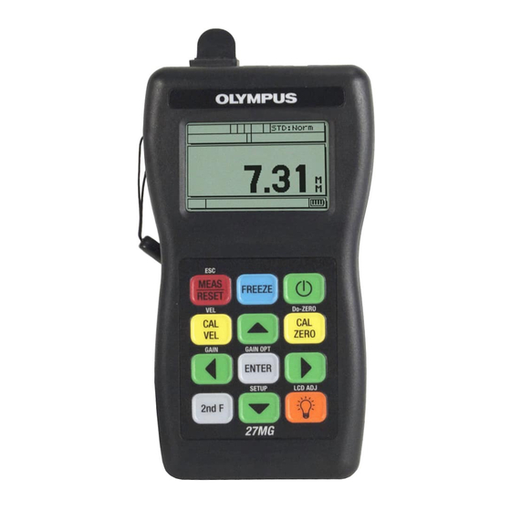
27MG
Ultrasonic Thickness Gage
User's Manual
This instruction manual contains essential information on how to use this Olympus product safely and effectively.
Before using this product, thoroughly review this instruction manual. Use the product as instructed.
Keep this instruction manual in a safe, accessible location.
DMTA-10043-01EN — Rev. C
July 2016
Advertisement
Chapters
Table of Contents

Related Manuals for Olympus 27MG


Summary of Contents for Olympus 27MG
- Page 1 DMTA-10043-01EN — Rev. C July 2016 This instruction manual contains essential information on how to use this Olympus product safely and effectively. Before using this product, thoroughly review this instruction manual. Use the product as instructed. Keep this instruction manual in a safe, accessible location.
- Page 2 Olympus Scientific Solutions Americas, 48 Woerd Avenue, Waltham, MA 02453, USA Copyright © 2013, 2014, 2016 by Olympus. All rights reserved. No part of this publication may be reproduced, translated, or distributed without the express written permission of Olympus. This document was prepared with particular attention to usage to ensure the accuracy of the information contained therein, and corresponds to the version of the product manufactured prior to the date appearing on the title page.
-
Page 3: Table Of Contents
DMTA-10043-01EN, Rev. C, July 2016 Table of Contents List of Abbreviations ..................vii Labels and Symbols ................... 1 Important Information — Please Read Before Use ........5 Intended Use .......................... 5 Instruction Manual ........................ 5 Instrument Compatibility ..................... 5 Repair and Modification ....................... 6 Safety Symbols ........................ - Page 4 Velocity and Zero Calibration ................. 36 Material Velocity Calibration .................. 37 Zero Calibration ......................39 6. Measurements ..................... 41 7. Additional 27MG Gaging Features ............43 Adjusting the Backlight .................... 44 Activating the Freeze Mode ..................45 Adjusting the Gain ....................45 Optimizing Material Gain Sensitivity ..............
- Page 5 DMTA-10043-01EN, Rev. C, July 2016 10.2 Transducer Selection ....................63 10.3 High Temperature Measurements ................. 66 11. Maintenance and Troubleshooting ............69 11.1 Routine Care and Maintenance ................69 11.2 Transducers Maintenance ..................69 11.3 Error Messages ......................70 11.4 Battery Problems ....................... 70 11.5 Setup (Do--) Problems ....................
-
Page 6: Dmta-10043-01En, Rev. C, July
DMTA-10043-01EN, Rev. C, July 2016 Table of Contents... -
Page 7: List Of Abbreviations
DMTA-10043-01EN, Rev. C, July 2016 List of Abbreviations DIAG diagnostic DIFF differential EFUP environment-friendly use period Ingress Protection loss-of-signal maximum minimum NiMH nickel-metal hydride portable document format transmit/receive universal serial bus List of Abbreviations... - Page 8 DMTA-10043-01EN, Rev. C, July 2016 viii List of Abbreviations...
-
Page 9: Labels And Symbols
Figure i-1 on page 1. The symbols are described in Table 1 on page 2 and Table 2 on page 3. If any or all of the labels or symbols are missing or illegible, please contact Olympus. Location of instruction and rating... -
Page 10: Table 1 Content Of The Instruction And Rating Label
The CE marking is a declaration that this product conforms to all the applicable directives of the European Community. See the Declaration of Conformity for details. Contact your Olympus representative for more information. The regulatory compliance mark (RCM) label indicates that... -
Page 11: Table 2 Content Of The Serial Number Label
The EFUP for the 27MG has been determined to be 15 years. Note: The Environment-Friendly Use Period (EFUP) is not meant to be interpreted as the period assuring functionality and product performance. - Page 12 DMTA-10043-01EN, Rev. C, July 2016 T/R1 and T/R2 connectors inner conductors Figure i‑2 Risk of electrical shock on T/R connectors inner conductors Labels and Symbols...
-
Page 13: Important Information - Please Read Before Use
The 27MG is designed to perform nondestructive inspections on industrial and commercial materials. Do not use the 27MG for any purpose other than its intended use. It must never be used to inspect or examine human or animal body parts. -
Page 14: Repair And Modification
Repair and Modification The 27MG does not contain any user-serviceable parts. Opening the instrument might void the warranty. In order to prevent human injury and/or equipment damage, do not disassemble, modify, or attempt to repair the instrument. -
Page 15: Safety Signal Words
DMTA-10043-01EN, Rev. C, July 2016 Safety Signal Words The following safety symbols might appear in the documentation of the instrument: The DANGER signal word indicates an imminently hazardous situation. It calls attention to a procedure, practice, or the like, which, if not correctly performed or adhered to, will result in death or serious personal injury. -
Page 16: Warnings
For any problem or question regarding this instrument, contact Olympus or an authorized Olympus representative. • Do not touch the connectors directly by hand. Otherwise, a malfunction or electric shock may result. -
Page 17: Battery Precautions
• Do not leave batteries in the 27MG unit during instrument storage. Equipment Disposal Before disposing of the 27MG, check your local laws, rules, and regulations, and follow them accordingly. CE (European Community) This device complies with the requirements of both directive 2004/108/EC concerning electromagnetic compatibility and directive 2006/95/EC concerning low voltage. -
Page 18: Weee Directive
Electronic Equipment (WEEE), this symbol indicates that the product must not be disposed of as unsorted municipal waste, but should be collected separately. Refer to your local Olympus distributor for return and/or collection systems available in your country. China RoHS China RoHS is the term used by industry generally to describe legislation implemented by the Ministry of Information Industry (MII) in the People’s Republic... -
Page 19: Korea Communications Commission (Kcc)
This equipment generates and uses radio-frequency energy and, if not installed and used properly (that is, in strict accordance with the manufacturer’s instructions), may cause interference. The 27MG has been tested and found to comply with the limits for an industrial device in accordance with the specifications of the EMC directive. -
Page 20: Ices-001 (Canada) Compliance
Retain packing materials, waybills, and other shipping documentation needed in order to file a damage claim. After notifying the carrier, contact Olympus for assistance with the damage claim and equipment replacement, if necessary. -
Page 21: Technical Support
Technical Support Olympus is firmly committed to providing the highest level of customer service and product support. If you experience any difficulties when using our product, or if it fails to operate as described in the documentation, first consult the user’s manual, and then, if you are still in need of assistance, contact our After-Sales Service. - Page 22 DMTA-10043-01EN, Rev. C, July 2016 Important Information — Please Read Before Use...
-
Page 23: Instrument Description
Ultrasonic Thickness Gage instrument. The portable document format (PDF) file for the 27MG Ultrasonic Thickness Gage — User’s Manual is included on the documentation CD that is shipped with the 27MG. Product Description The 27MG instrument is a handheld ultrasonic thickness gage designed for a wide variety of thickness-measurement applications. -
Page 24: Environmental Ratings
Instrument Hardware Components The 27MG front panel features a display and a keypad. The instrument comes with a wrist strap. An optional protective rubber boot includes strap rings at the four corners (see Figure 1-1 on page 17). -
Page 25: Connectors
Figure 1‑2 The 27MG connections The universal serial bus (USB) and Transmit/Receive transducer connectors are located on the top of the 27MG (see Figure 1-3 on page 18). The USB connector on the 27MG is only used for upgrading the internal operating software. -
Page 26: Keypad Functions
Figure 1‑3 The top end connectors Keypad Functions The 27MG comes either with the English or the international keypad (see Figure 1-4 on page 18). The functions are the same for both keypads. On the international keypad, the text labels on many keys are replaced by pictograms. In this document, keypad keys are referred to using the English label in bold and within brackets (ex.:... -
Page 27: Table 3 Keypad Functions
Use the [MEAS] key at any time to return to the measurement screen. The yellow keys are related to calibration. Table 3 on page 19 lists the key functions available on the 27MG keypad. Table 3 Keypad functions English... - Page 28 DMTA-10043-01EN, Rev. C, July 2016 Table 3 Keypad functions (continued) English International Functions Down arrow • In a screen or a list, moves to the next element. • For some parameters, decreases the value of a numerical entry. Left arrow •...
- Page 29 DMTA-10043-01EN, Rev. C, July 2016 Table 3 Keypad functions (continued) English International Functions Power — Turns the instrument power on or off. LCD Adjust — Turns on or off the backlight feature that internally illuminates the LCD screen. Instrument Description...
- Page 30 DMTA-10043-01EN, Rev. C, July 2016 Chapter 1...
-
Page 31: Mg Power Requirements
Power Indicator The battery indicator is always present on the bottom-right corner of the screen. The 27MG can be powered by three AA-sized batteries, by a computer through its USB connector, or by a commercially available 5-volt USB power supply. -
Page 32: Batteries
When the batteries are full (100 % level), the battery power indicator will show four bars (see Figure 2-1 on page 23). When the 27MG instrument is not being used for a prolonged period of time, remove the batteries and store them by doing the following: •... -
Page 33: Figure 2-2 Opening The Battery Compartment
To replace the batteries Ensure that the 27MG is turned off. Disconnect any cables that are connected to the 27MG. Remove the optional protective rubber boot, if installed. Unscrew the captive screw on the battery door screw by turning it counterclockwise. -
Page 34: Figure 2-3 Selecting The Battery Type
Reinstall the optional protective rubber boot, if required. 10. Press the power [ ] button to turn on the 27MG instrument. 11. To answer the battery type setup question displayed at the bottom of the screen, use the right or left arrow keys, and then press [ENTER] (see Figure 2-3 on page 26): —... -
Page 35: Software User Interface Elements
Battery power indicator Figure 3‑1 The measurement screen The measurement screen is the main screen of the 27MG software. From anywhere in the 27MG software, simply press [MEAS] to return to the measurement screen. The power indicator is always present on the bottom-right corner of the 27MG screen (see “Power Indicator”... -
Page 36: Parameter Screens
Figure 3‑2 Other elements of the measurement screen Parameter Screens The 27MG setup parameters are logically grouped in tabs that can be accessed using the [2 F] and down arrow [] (SETUP) front panel keys. Figure 3-3 on page 29 shows the MEAS tab as an example. -
Page 37: Figure 3-3 Parameter Screen Example
DMTA-10043-01EN, Rev. C, July 2016 Tab from which the screen Title bar is accessed Parameters Help messages Figure 3‑3 Parameter screen example In the remainder of this document, the above procedure is summarized by the simple instruction to select a specific parameter or list, and its value. For example: In the MEAS tab, set UNITS to INCHES. - Page 38 DMTA-10043-01EN, Rev. C, July 2016 Chapter 3...
-
Page 39: Initial Setup
DMTA-10043-01EN, Rev. C, July 2016 4. Initial Setup This chapter demonstrates basic 27MG setup techniques. The unit is shipped from the factory, setup with the default conditions provided in Table 4 on page 31. Table 4 Default conditions Condition Comment Standard 0.01 mm (0.001 in.) -
Page 40: Figure 4-1 Transducer Zero Compensation
5.740 mm/µs (0.2260 in./µs). Therefore, if you find the default value gives inaccurate results on your material, refer to the calibration instructions. To operate the 27MG Ultrasonic Thickness Gage for the first time, the initial setup must be completed. -
Page 41: Figure 4-2 The Zero Screen
DMTA-10043-01EN, Rev. C, July 2016 This means that the gage requires the following transducer zero compensation step. Wipe any couplant from the tip of the transducer. Press [2 F], [CAL ZERO] (Do‑ZERO). The gage displays a zero value and then displays the measurement screen (see Figure 4-2 on page 33). - Page 42 DMTA-10043-01EN, Rev. C, July 2016 Chapter 4...
-
Page 43: Standard Calibration Measurement
27MG Ultrasonic Thickness Gage must be properly calibrated. Introduction The 27MG calibration procedure adjusts the gage so that it measures accurately on a particular material, using a particular transducer at a particular temperature. Calibration procedures include: •... -
Page 44: Transducer Zero Compensation
DMTA-10043-01EN, Rev. C, July 2016 Transducer Zero Compensation This step must be done whenever the message Do‑‑ and the DO ZERO flag are displayed (see Figure 5-1 on page 36). Figure 5‑1 The Do‑‑ screen To do the transducer zero compensation, wipe any couplant from the transducer face, and press [2 F], [CAL ZERO] (Do‑ZERO). -
Page 45: Material Velocity Calibration
DMTA-10043-01EN, Rev. C, July 2016 Uncouple the transducer from the block and use the [], [], [], and [] arrow keys to enter the thickness of the thick block. Couple the transducer to the thin block and press [CAL ZERO] or [Cal Ø]. When the reading is stable, press [ENTER] or []. -
Page 46: Figure 5-2 The Unknown Sound Material Do-- Screen
DMTA-10043-01EN, Rev. C, July 2016 5.4.1 When Material Sound Velocity Is Unknown To perform the material velocity calibration, a calibration block made from the material to be measured must be used. The block should be approximately as thick as the thickest section to be measured and have flat, smooth, and parallel front and back surfaces. -
Page 47: Zero Calibration
DMTA-10043-01EN, Rev. C, July 2016 F], [CAL VEL] (VEL) may be pressed following velocity calibration (or at any time in measurement mode) in order to read and record the material velocity for this particular material. When measuring this material in the future, this velocity may be entered by means of the arrow keys, without using the block. - Page 48 DMTA-10043-01EN, Rev. C, July 2016 To perform the zero calibration Update the transducer zero compensation by wiping the transducer face clean of all couplant and pressing [2 F], [CAL ZERO] (Do‑ZERO) while in measurement mode. Couple the transducer to the standard. Press the [CAL ZERO] key.
-
Page 49: Measurements
DMTA-10043-01EN, Rev. C, July 2016 6. Measurements Once the initial setup of the 27MG Ultrasonic Thickness Gage has been performed (see chapter “Initial Setup” on page 31) and a standard calibration has been completed (see “Standard Calibration Measurement” on page 35), measurements can be made. - Page 50 DMTA-10043-01EN, Rev. C, July 2016 Chapter 6...
-
Page 51: Additional 27Mg Gaging Features
DMTA-10043-01EN, Rev. C, July 2016 7. Additional 27MG Gaging Features The 27MG Ultrasonic Thickness Gage has several additional convenient features. The use of these features is not required for basic operation. However, they make the gage a more versatile instrument. -
Page 52: Adjusting The Backlight
Use the [] and [] keys to change between NORMAL and AUTO. Press [MEAS] to return to measurement mode with the new settings. To adjust contrast The contrast adjustment feature allows the 27MG Ultrasonic Thickness Gage to adjust the contrast (light or dark) of the display. To adjust the display contrast... -
Page 53: Activating The Freeze Mode
The material gain sensitivity optimization feature allows the normal measurement sensitivity to be increased or decreased by an amount related to the measured peak noise in a specific transducer and material combination. Normally, the 27MG Ultrasonic Thickness Gage adjusts the receiver gain and detection level depending on both the transducer type and the received echo characteristics. -
Page 54: Restoring The Default Gain
F], [] (GAIN). Configuring the Measurement Setup The measurement setup menu allows the user to turn on or off many of the additional measurement features of the 27MG Ultrasonic Thickness Gage. Measurement setup features include the following functions: • Units •... - Page 55 The Min/Max mode allows the user to put the gage in minimum (MIN) or maximum (MAX) scanning mode. This feature allows the user to scan over an area and quickly determine the minimum or maximum thickness. Additional 27MG Gaging Features...
- Page 56 The minimum values are retained in a temporary memory until new minimum thickness values replace them or until the [MEAS] key is pressed to reset the minimum. When MIN is selected, the 27MG automatically changes to 20 Hz fast update mode.
- Page 57 The Measure Rate parameter allows the user to display the measurement update rate. The user can select between NORMAL (4 Hz) and FAST (20 Hz). Changing to the fast update rate will greatly affect the battery life of the 27MG Ultrasonic Thickness Gage.
-
Page 58: Configuring The System Setup
DMTA-10043-01EN, Rev. C, July 2016 Configuring the System Setup The System Setup functions allow the user to turn on or off many 27MG Ultrasonic Thickness Gage configurations. They are available on the SYSTEM tab. The SYSTEM tab gives access to the following functions: •... - Page 59 When BACKLIGHT mode is set to AUTO and the backlight is turned on, it will stay on while a thickness measurement is being displayed and automatically turn off five seconds after a loss-of-signal (LOS) has occurred. To change the Backlight mode Press [2 F] [] (SETUP) to display the setup tabs. Additional 27MG Gaging Features...
-
Page 60: Activating High/Low Alarms
DMTA-10043-01EN, Rev. C, July 2016 Use the [, ] keys to highlight the SYSTEM tab. Use the [] key to highlight BACKLIGHT mode and [, ] to select between NORMAL and AUTO. Press [MEAS] to return to measurement mode. Activating High/Low Alarms The High/Low alarm allows the user to establish high and low alarm set points. -
Page 61: Activating Diff Mode
Press [MEAS] to return to measurement mode. 7.10 Resetting the Instrument Parameters Resets are used to reset the operating software of the 27MG Ultrasonic Thickness Gage to their factory default settings. Three resets can be performed: Measurement, Master, and Database. - Page 62 DMTA-10043-01EN, Rev. C, July 2016 7.10.1 Resetting Measurement Parameters The Measurement Reset function resets the measurement parameters to their default values. The parameters that are reset and their reset values are as follow: • Material Velocity (0.5740 mm/µs [0.2260 in/µs]) •...
- Page 63 Use the [, ] keys to highlight the RESET tab. Use the [] key to highlight MASTER RESET and press [ENTER]. Use the [, ] keys to highlight RESET or CANCEL and press [ENTER]. Press [MEAS] to return to measurement mode. Additional 27MG Gaging Features...
- Page 64 DMTA-10043-01EN, Rev. C, July 2016 Chapter 7...
-
Page 65: Specifications
DMTA-10043-01EN, Rev. C, July 2016 8. Specifications Table 5 on page 57 contains the general specifications for the 27MG Ultrasonic Thickness Gage. Table 5 Specifications Parameter Value Measurements Dual element transducer Time interval from a precision delay after the excitation measurement mode pulse to the first echo. - Page 66 DMTA-10043-01EN, Rev. C, July 2016 Table 5 Specifications (continued) Parameter Value Battery operating time 150 h of typical battery life 30 h continuous use with backlight. Explosive Atmosphere Safe operation as defined by Class I, Division 2, Group D, as found in the National Fire Protection Association Code (NFPA 70), Article 500, and tested using MIL-STD-810F 511.4 Procedure I.
-
Page 67: Theory Of Operation
DMTA-10043-01EN, Rev. C, July 2016 9. Theory of Operation The 27MG Ultrasonic Thickness Gage operates on the dual transducer pulse-echo principal, timing the reflection of high-frequency sound waves from the back wall of the test piece. This technique, derived from sonar, has been widely applied to nondestructive testing. -
Page 68: Figure 9-1 27Mg Block Diagram
RAM (random access memory). The keyboard informs the microprocessor of user-entered changes of mode, values, and so on. Power Battery supply Control and Detector Pulser amplifier Measure Keyboard Transducer For software upgrade only Figure 9‑1 27MG block diagram Chapter 9... -
Page 69: Application Notes
10.1 Factors Affecting Performance and Accuracy The following factors can affect the performance and the accuracy of the 27MG Ultrasonic Thickness Gage: • Surface Condition Severe pitting on the outside surface of a pipe or tank can be a problem. -
Page 70: Figure 10-1 Perpendicular To Center Axis Alignment On Pipe
DMTA-10043-01EN, Rev. C, July 2016 so that the sound barrier material visible on the probe face is aligned perpendicularly to the center axis of the pipe (see Figure 10-1 on page 62). Figure 10‑1 Perpendicular to center axis alignment on pipe It is possible that on some severely corroded or pitted materials there will be spots where readings cannot be obtained. -
Page 71: Transducer Selection
Table 6 on page 64 lists approximate minimum measurable thicknesses in steel for the standard transducers used with the 27MG Ultrasonic Thickness Gage. Note that these numbers are approximate. The exact measurable minimum in a given application depends on material velocity, surface condition, temperature, and geometry, and it should be determined experimentally by the user. -
Page 72: Table 6 Transducer Selection
DMTA-10043-01EN, Rev. C, July 2016 Table 6 Transducer selection Range Temperature Probe Connector diameter (steel) range D7910 Right angle 12.7 mm 1 mm to 0 °C to 50 °C (0.50 in.) 254 mm (32 °F to (0.040 in. to 122 °F) 10 in.) D790 Straight... - Page 73 Not all duals are designed for high temperature measurements. The chart above lists recommended temperature ranges for the duals used with the 27MG Ultrasonic Thickness Gage. For other transducers, consult the manufacturer. Using a transducer on materials whose temperature is beyond the specified range can damage or destroy the transducer.
-
Page 74: High Temperature Measurements
Olympus Couplant (H-2) can be used at temperatures up to 398 °C (750 °F), although it will boil as the upper limit is reached. - Page 75 Gain Adjust procedure or the Material Sensitivity Optimization procedure. High temperature couplants are generally less efficient than those used at lower temperatures, so the 27MG will work better when sensitivity is adjusted or optimized to accommodate high temperature conditions.
- Page 76 DMTA-10043-01EN, Rev. C, July 2016 Chapter 10...
-
Page 77: Maintenance And Troubleshooting
This chapter describes how to maintain your 27MG instrument by carrying out routine care and maintenance. 11.1 Routine Care and Maintenance The 27MG case is sealed to prevent intrusion of environmental liquids and dust. However, it is not completely waterproof. Therefore, the unit should never be immersed in any fluid. -
Page 78: Error Messages
Consult Olympus for further information. 11.4 Battery Problems The bars on the batteries symbol show operating time remaining. If the 27MG Ultrasonic Thickness Gage turns off immediately after it is turned on, or if it does not turn on at all, then the battery is probably completely discharged. The batteries should be replaced. -
Page 79: Self Diagnostics
If the above tests indicate that there is a problem with the gage or transducer, then the unit(s) may be returned to Olympus for repair or replacement. If the above tests indicate that the gage and transducer are good, the test material itself probably cannot be measured due to: —... -
Page 80: Table 8 Diag1 Results
(RCVR2) Highlighted parameters indicate that the specific self-test failed based on the expected values. To view the Diagnostic 2 screen, which shows information about your 27MG instrument Press [2 F] [] (SETUP) to display the setup tabs. Use the [, ] keys to highlight the DIAG2 tab. -
Page 81: Gage Performance Tests
If PR TX displays N/A, then either the cable is broken or there is a problem with the transducer. 11.8 Gage Performance Tests The 27MG Ultrasonic Thickness Gage TESTS screen includes two test functions of gage performance (see Figure 11-1 on page 73): •... -
Page 82: Figure 11-2 Keypad Test
DMTA-10043-01EN, Rev. C, July 2016 Figure 11‑2 Keypad test To test the keypad From the measurement (MEAS) screen, press [2 F] [] and use the [] arrow to move across the top of the screen to the TESTS tab. Press the [] arrow to select KEYPAD TEST and then press [ENTER] to start the test, or press [2 F] [] to abort the test. -
Page 83: Repair Service
Olympus will repair any 27MG Ultrasonic Thickness Gage at its Waltham, Massachusetts, USA factory. In addition, some local Olympus dealers can perform repairs. 11.10 Replacement Parts, Optional Parts, and Equipment Replacement parts for the 27MG as well as additional related equipment are available from Olympus. Maintenance and Troubleshooting... - Page 84 DMTA-10043-01EN, Rev. C, July 2016 Chapter 11...
-
Page 85: Appendix: Sound Velocities
DMTA-10043-01EN, Rev. C, July 2016 Appendix: Sound Velocities Table 10 on page 77 presents a tabulation of the ultrasonic velocity in a variety of common materials. It is provided only as a guide. The actual velocity in these materials may vary significantly for a variety of reasons, such as: composition, preferred crystallographic orientation, porosity, and temperature. - Page 86 DMTA-10043-01EN, Rev. C, July 2016 Table 10 Ultrasonic velocities (continued) Material V (in./µs) V (m/s) Lucite 0.106 2680 Molybdenum 0.246 6250 Motor oil (SAE 20/30) 0.069 1740 Nickel, pure 0.222 5630 Polyamide (slow) 0.087 2200 Nylon, fast 0.102 2600 Polyethylene, high 0.097 2460 density (HDPE)
- Page 87 DMTA-10043-01EN, Rev. C, July 2016 Table 10 Ultrasonic velocities (continued) Material V (in./µs) V (m/s) Tungsten 0.204 5180 Water (20 °C [68 °F]) 0.0580 1480 Zinc 0.164 4170 Zirconium 0.183 4650 References W.P. Mason, Physical Acoustics and the Properties of Solids, D. Van Nostrand Co., New York, 1958.
- Page 88 DMTA-10043-01EN, Rev. C, July 2016 Appendix...
-
Page 89: List Of Figures
DMTA-10043-01EN, Rev. C, July 2016 List of Figures Figure 1-1 The 27MG hardware components — Front and top views ......17 Figure 1-2 The 27MG connections ..................17 Figure 1-3 The top end connectors ..................18 Figure 1-4 The 27MG keypads .................... 18 Figure 2-1 The power indicator when using batteries ............ - Page 90 DMTA-10043-01EN, Rev. C, July 2016 List of Figures...
-
Page 91: List Of Tables
DMTA-10043-01EN, Rev. C, July 2016 List of Tables Table 1 Content of the instruction and rating label ............2 Table 2 Content of the serial number label ............... 3 Table 3 Keypad functions ....................19 Table 4 Default conditions ....................31 Table 5 Specifications ...................... - Page 92 DMTA-10043-01EN, Rev. C, July 2016 List of Tables...
-
Page 93: Index
DMTA-10043-01EN, Rev. C, July 2016 Index Numerics NiMH rechargeable 24 using 24 F key 19 beeper, audio alarm 50 Blank mode, LCD display 31 acoustic properties, material 62 boot, protective rubber 16 additional features 43 alarm mode, programmable 58 CAL LOCK See calibration lock function alkaline batteries See batteries CAL VEL key 20 arrow keys 19... - Page 94 DMTA-10043-01EN, Rev. C, July 2016 EMC directive 11 environmental rating 16 FCC (USA) 11 equipment disposal 9 ICES-001 (Canada) 12 error messages 70 RCM (Australia) 2 ESC secondary key 19 connections 17 explosive atmosphere, safe operation connectors (NFPA 70) 58 conventional transducer 4 Transmit/Receive 4, 17 FCC (USA) compliance 11...
- Page 95 DMTA-10043-01EN, Rev. C, July 2016 display resolution 57 Korea Communications Commission (KCC) changing 47 marking 3 intended use 5 symbol 11 measurement techniques 31 Korean standard See Korea Communications modification prohibited 6 Commission (KCC) power requirements 23 repair 6 labels 1 strap ring 17 instruction and rating turning on or off 17...
- Page 96 (NFPA 70) 58 NOTE signal word 8 safety notes, information, signal words 7 instrument compatibility 6 misuse of instrument 5 Olympus technical support 13 signal words 7 on/off key See keys, power symbols 6 operating temperature range, instrument 57 screens...
- Page 97 DMTA-10043-01EN, Rev. C, July 2016 NOTE 8 dual element ~, measurement mode 57 TIP 8 frequency range 57 safety 7 high temperature measurements 65 CAUTION 7 maintenance 69 DANGER 7 positioning/alignment 61 WARNING 7 selection 63 sound attenuation 63 zero compensation 35 sound scattering 62 Transmit/Receive connectors 4, 17 sound velocity 77...
- Page 98 DMTA-10043-01EN, Rev. C, July 2016 Index...
Need help?
Do you have a question about the 27MG and is the answer not in the manual?
Questions and answers
After cal zero display showing somwe number inated os zero
When the Olympus 27MG displays a number after calibrating to zero, it is showing the zero calibration value. This value appears momentarily after performing the transducer zero compensation using the CAL ZERO procedure.
This answer is automatically generated