Table of Contents
Advertisement
Quick Links
38DL PLUS
Ultrasonic Thickness Gage
Basic Operation Manual
This instruction manual contains essential information on how to use this Olympus product safely and effectively.
Before using this product, thoroughly review this instruction manual. Use the product as instructed.
Keep this instruction manual in a safe, accessible location.
DMTA-10009-01EN [U8778346] — Rev. D
November 2016
Advertisement
Chapters
Table of Contents

Related Manuals for Olympus 38DL PLUS


Summary of Contents for Olympus 38DL PLUS
- Page 1 DMTA-10009-01EN [U8778346] — Rev. D November 2016 This instruction manual contains essential information on how to use this Olympus product safely and effectively. Before using this product, thoroughly review this instruction manual. Use the product as instructed. Keep this instruction manual in a safe, accessible location.
- Page 2 Olympus Scientific Solutions Americas, 48 Woerd Avenue, Waltham, MA 02453, USA Copyright © 2010, 2011, 2016 by Olympus. All rights reserved. No part of this publication may be reproduced, translated, or distributed without the express written permission of Olympus. This document was prepared with particular attention to usage to ensure the accuracy of the information contained therein, and corresponds to the version of the product manufactured prior to the date appearing on the title page.
-
Page 3: Table Of Contents
DMTA-10009-01EN [U8778346], Rev. D, November 2016 Table of Contents List of Abbreviations ..................vii Labels and Symbols ................... 1 Important Information — Please Read Before Use ........5 Intended Use .......................... 5 Instruction Manual ........................ 5 Instrument Compatibility ..................... 6 Repair and Modification ....................... - Page 4 Product Description ....................19 Environmental Ratings ..................... 22 Instrument Hardware Components ............... 23 Connectors ......................... 24 Keypad Functions ..................... 26 2. Powering the 38DL PLUS ................. 31 Power Indicator ......................31 Using the AC Power ....................32 Using Battery Power ....................33 2.3.1 Battery Operating Time .................
- Page 5 DMTA-10009-01EN [U8778346], Rev. D, November 2016 5.2.1 Calibrating the Instrument ................67 5.2.2 Test Blocks ....................... 70 5.2.3 Transducer Zero Compensation ..............70 5.2.4 Material Sound Velocity and the Zero Calibrations ......... 71 5.2.5 Entering a Known Material Sound Velocity ..........72 5.2.6 Locked Calibrations ..................
-
Page 6: Dmta-10009-01En [U8778346], Rev. D, November
DMTA-10009-01EN [U8778346], Rev. D, November 2016 Table of Contents... -
Page 7: List Of Abbreviations
DMTA-10009-01EN [U8778346], Rev. D, November 2016 List of Abbreviations alternative current AEtoE automatic echo-to-echo average database direct current EFUP environment-friendly use period EMAT electromagnetic acoustic transducer high identification Li-ion lithium-ion loss-of-signal main bang MEtoE manual echo-to-echo military NiMH nickel metal hydride part number portable document format pulse repetition frequency... - Page 8 DMTA-10009-01EN [U8778346], Rev. D, November 2016 viii List of Abbreviations...
-
Page 9: Labels And Symbols
Safety-related labels and symbols are attached to the instrument at the locations shown in Figure i-1 on page 1 and Figure i-2 on page 2. If any or all of the labels or symbols are missing or illegible, please contact Olympus. CAUTION Do not touch the inner conductor of the T/R 1 and T/R 2 connectors to avoid risks of an electric shock. -
Page 10: Figure I-2 Labels And Symbols Are Attached To The Instrument
DMTA-10009-01EN [U8778346], Rev. D, November 2016 Side view Back view Patent label Serial number label Instruction label (see Table 1 on page 3) Serial number label Figure i‑2 Labels and symbols are attached to the instrument Labels and Symbols... -
Page 11: Table 1 Label Contents
DMTA-10009-01EN [U8778346], Rev. D, November 2016 Table 1 Label contents Serial number yynnnnnmm label Where: yy: last two digits of the production year nnnnn: 5-digit nonduplicated incrementing number representing the n production unit of this product mm: production month Instruction label Labels and Symbols... - Page 12 The EFUP for the 38DL PLUS has been determined to be 15 years. Note: The Environment-Friendly Use Period (EFUP) is not meant to be interpreted as the period assuring functionality and product performance.
-
Page 13: Important Information - Please Read Before Use
The 38DL PLUS instrument has been designed to measure thicknesses of industrial and commercial materials. WARNING Do not use the 38DL PLUS for any purpose other than its intended use. It must never be used to inspect or examine human or animal body parts. Instruction Manual This instruction manual contains essential information on how to use this Olympus product safely and effectively. -
Page 14: Instrument Compatibility
PDF file can be found on the GageView CD (P/N: Gageview [U8147006]). GageView Interface Program — User’s Manual (P/N: 910-259-EN [U8778347]) The 38DL PLUS also works with the GageView interface program. Refer to this document for detailed information on GageView. The document is available in PDF format on the GageView CD and as online help in GageView. -
Page 15: Repair And Modification
DMTA-10009-01EN [U8778346], Rev. D, November 2016 Repair and Modification Apart from the battery, the 38DL PLUS does not contain any user-serviceable parts. Opening the instrument might void the warranty. CAUTION In order to prevent human injury and/or equipment damage, do not disassemble, modify, or attempt to repair the instrument. -
Page 16: Note Signal Words
DMTA-10009-01EN [U8778346], Rev. D, November 2016 DANGER The DANGER signal word indicates an imminently hazardous situation. It calls attention to a procedure, practice, or the like that if not correctly performed or adhered to will result in death or serious personal injury. Do not proceed beyond a DANGER signal word until the indicated conditions are fully understood and met. -
Page 17: Safety
For any problem or question regarding this instrument, contact Olympus or an authorized Olympus representative. • Do not touch the connectors directly by hand. Otherwise, a malfunction or electric shock may result. -
Page 18: Battery Precautions
The instrument must only be connected to a power source corresponding to the type indicated on the rating label. CAUTION If an unauthorized power supply cord is used to power the instrument or charge the batteries, Olympus cannot guarantee the electrical safety of the equipment. Battery Precautions CAUTION •... -
Page 19: Equipment Disposal
Do not expose a battery to moisture or rain; doing so could cause an electric shock. • Only use the 38DL PLUS unit or an external charger approved by Olympus to charge the batteries. • Only use batteries supplied by Olympus. -
Page 20: Weee Directive
Electronic Equipment (WEEE), this symbol indicates that the product must not be disposed of as unsorted municipal waste, but should be collected separately. Refer to your local Olympus distributor for return and/or collection systems available in your country. China RoHS China RoHS is the term used by industry generally to describe legislation implemented by the Ministry of Information Industry (MII) in the People’s Republic... -
Page 21: Emc Directive Compliance
This equipment generates and uses radio-frequency energy and, if not installed and used properly (that is, in strict accordance with the manufacturer’s instructions), may cause interference. The 38DL PLUS has been tested and found to comply with the limits for an industrial device in accordance with the specifications of the EMC directive. -
Page 22: Ices-001 (Canada) Compliance
This Class A digital apparatus complies with Canadian ICES-001. Cet appareil numérique de la classe A est conforme à la norme NMB-001 du Canada. Regulatory Information The 38DL PLUS may display a regulatory screen that lists the specific regulation with which it complies. To view the REGULATORY screen In the measurement screen, press [2nd F], [SETUP MENU] (SP MENU). -
Page 23: Technical Support
Retain packing materials, waybills, and other shipping documentation needed in order to file a damage claim. After notifying the carrier, contact Olympus for assistance with the damage claim and equipment replacement, if necessary. - Page 24 DMTA-10009-01EN [U8778346], Rev. D, November 2016 Important Information — Please Read Before Use...
-
Page 25: Introduction
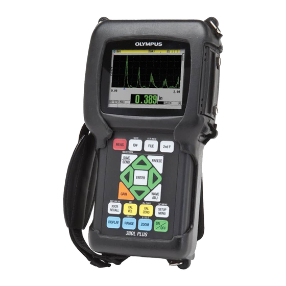
IMPORTANT For advanced instructions on instrument configuration, use, troubleshooting, and maintenance, refer to the 38DL PLUS User’s Manual. The list of other 38DL PLUS documents is provided in “Instruction Manual” on page 5. Figure i‑3 The 38DL PLUS instrument... - Page 26 DMTA-10009-01EN [U8778346], Rev. D, November 2016 Introduction...
-
Page 27: Instrument Description
You can find the PDF file of the 38DL PLUS Ultrasonic Thickness Gage — User’s Manual (P/N: DMTA-10004-01EN) on the GageView CD (P/N: Gageview [U8147006]) that is included with the 38DL PLUS kit. -
Page 28: Figure 1-1 Measuring Thicknesses With The 38Dl Plus
You can also use single element or dual element transducers for echo-to-echo measurements. You can connect the 38DL PLUS to a printer and to a computer using the bidirectional serial USB/RS-232 communication ports. Advanced Measurement Features •... - Page 29 DMTA-10009-01EN [U8778346], Rev. D, November 2016 • EMAT transducer capability • Measurement-related status flags and alarms • Full VGA color transflective LED back-lite display • Automatic probe recognition for the standard D79X and MTD705 series transducers • Dynamic default gain optimization •...
-
Page 30: Environmental Ratings
• Standard USB and RS-232 directional communication Environmental Ratings The 38DL PLUS is a rugged and durable instrument that you may use in harsh environments. The 38DL PLUS was designed to meet the requirement of the IP67 standard (Ingress Protection). -
Page 31: Instrument Hardware Components
Instrument Hardware Components The 38DL PLUS front panel features a color display and a keypad. The instrument comes with a hand strap. A protective rubber boot includes a dust flap seal for the DC power and serial communication connectors, strap rings at the four corners, and a stand at the back (see Figure 1-2 on page 23). -
Page 32: Connectors
38DL PLUS. Do not use this AC power cord with other products. The DC power, USB/RS-232 communication, and Transmit/Receive probe connectors are located on the top end of the 38DL PLUS (see Figure 1-4 on page 25). Chapter 1... -
Page 33: Figure 1-4 The Top End Connectors
DMTA-10009-01EN [U8778346], Rev. D, November 2016 USB/RS-232 serial Transmit/Receive communication connector transducer connector 2 DC power connector Transmit/Receive transducer connector 1 Figure 1‑4 The top end connectors The USB client connector, the VGA output connector, and the external microSD memory card slot are located on the right side of the instrument, hidden behind the I/O door (see Figure 1-5 on page 25). -
Page 34: Keypad Functions
DMTA-10009-01EN [U8778346], Rev. D, November 2016 Keypad Functions The 38DL PLUS comes either with the English, international, Chinese, or Japanese keypad (see Figure 1-6 on page 26). The functions are the same for all keypads. On the international keypad, the text labels on many keys are replaced by pictograms. In this document, keypad keys are referred to using the English label in bold and within brackets (ex.: [MEAS]). -
Page 35: Table 2 Keypad Functions
The yellow keys are related to calibration. The blue keys are related to the display configuration. Table 2 on page 27 lists the key functions available from the 38DL PLUS keypad. Table 2 Keypad functions... - Page 36 DMTA-10009-01EN [U8778346], Rev. D, November 2016 Table 2 Keypad functions (continued) English International Functions Save waveform — Stores a measurement and the corresponding waveform in the datalogger at the current ID number. Freeze — Causes the displayed waveform to immediately hold until the key is pressed again. Gain —...
- Page 37 DMTA-10009-01EN [U8778346], Rev. D, November 2016 Table 2 Keypad functions (continued) English International Functions Right arrow • Selects the next available value for the selected parameter. • In text edit mode, moves the cursor one character position to the right. Transducer recall —...
- Page 38 DMTA-10009-01EN [U8778346], Rev. D, November 2016 Table 2 Keypad functions (continued) English International Functions Setup menu — Provides access to instrument parameters (measurement, system, alarm, differential mode, communication, B-scan, DB grid, avg/min, temperature correction, multilayer [optional], oxide [optional], password set, instrument lock).
-
Page 39: Powering The 38Dl Plus
DMTA-10009-01EN [U8778346], Rev. D, November 2016 2. Powering the 38DL PLUS This chapter describes how to operate the 38DL PLUS using different power supply options. Power Indicator The power indicator is always present on the right side of the screen. It shows the level of the battery charge and on which type of power the instrument operates (see Figure 2-1 on page 31). -
Page 40: Using The Ac Power
(see Figure 2-2 on page 32). CAUTION To avoid the risk of injuries or equipment damage, use only the AC power cord supplied with the 38DL PLUS. Do not use this AC power cord with other products. DC power plug... -
Page 41: Using Battery Power
[U8780290]). The 38DL PLUS does not recharge NiMH batteries. You must recharge AA batteries with an external battery charger (not included). NOTE The 38DL PLUS battery is not fully charged when shipped. You must fully charge the battery before operating the instrument from the battery power. Powering the 38DL PLUS... -
Page 42: Battery Operating Time
To charge the internal battery Connect the 38DL PLUS using the AC power (see “Using the AC Power” on page 32). The battery charges when the instrument is ON or OFF, but the rate of charge is slower when the instrument is ON. - Page 43 Store batteries in a cool, dry environment. • Avoid long-term storage under sunlight or in other excessively hot places such as the trunk of an automobile. • While in storage, fully recharge batteries at least once every two (2) months. Powering the 38DL PLUS...
-
Page 44: Replacing The Battery
Olympus battery (P/N: 38-BAT [U8760054]). To replace the battery Disconnect the instrument from the charger/adaptor. Ensure that the 38DL PLUS power is off. Disconnect any other cable connected to the 38DL PLUS. Remove the hand strap. Remove the protective rubber boot. Chapter 2... -
Page 45: Figure 2-5 Selecting The New Battery Type
12. Reinstall the protective rubber boot and the hand strap. 13. Press [ON/OFF] to turn on the 38DL PLUS. 14. To answer the question appearing at the bottom of the screen (see Figure 2-5 on page 37): ... - Page 46 DMTA-10009-01EN [U8778346], Rev. D, November 2016 Chapter 2...
-
Page 47: Software User Interface Elements
(see Figure 3-1 on page 39). The measurement screen is the main screen of the 38DL PLUS software. From anywhere in the 38DL PLUS software, simply press [MEAS] to return to the measurement screen. -
Page 48: Figure 3-2 The Id Bar
I/O door on the right side of the instrument (see Figure 1-5 on page 25). The 38DL PLUS recognizes an external microSD memory card when you start the instrument. -
Page 49: Menus And Submenus
Figure 3‑4 The loss‑of‑signal (LOS) indicator Menus and Submenus The 38DL PLUS displays menus and submenus when you press some of the front panel keys. The menu appears at the top-left corner of the screen (see Figure 3-5 on page 42). If applicable, a submenu also appears, conveniently showing the parameters available for the highlighted menu command. -
Page 50: Parameter Screens
For example: “In the menu, select MEAS.” Parameter Screens The 38DL PLUS parameters are logically grouped in parameter screens that you access using front panel keys or menu commands. Figure 3-6 on page 43 shows the MEAS parameter screen as an example. -
Page 51: Figure 3-6 Parameter Screen Example
DMTA-10009-01EN [U8778346], Rev. D, November 2016 Title bar Menu from which the screen is accessed Parameters Help text bars Figure 3‑6 Parameter screen example The title bar, located at the top of the parameter screen, indicates the parameter subject. When you access a parameter screen from a menu, a menu button appears on the left side of the title bar. -
Page 52: Selecting The Text Edit Mode
“In the MEAS screen, set MEASUREMENT MODE to THICKNESS.” Selecting the Text Edit Mode The 38DL PLUS offers two methods to edit the value of alphanumeric parameters. You can either use the virtual keyboard or the traditional method. The virtual keyboard appears on the screen to show all the available characters that you can use (see “Editing Text Parameters Using the Virtual Keyboard”... -
Page 53: Figure 3-7 Example Of The Virtual Keyboard
DMTA-10009-01EN [U8778346], Rev. D, November 2016 Title bar Parameter value text Selected alphanumeric parameter Virtual keyboard Help text bars Figure 3‑7 Example of the virtual keyboard To edit an alphanumeric parameter value using the virtual keyboard Select an alphanumeric parameter. The virtual keyboard appears. -
Page 54: Editing Text Parameters Using The Traditional Method
DMTA-10009-01EN [U8778346], Rev. D, November 2016 If you want to cancel the editing operation and return to the original parameter value, on the virtual keyboard, highlight CANCEL, and then press [ENTER]. To complete the editing of the parameter value, on the virtual keyboard, highlight DONE, and then press [ENTER]. - Page 55 DMTA-10009-01EN [U8778346], Rev. D, November 2016 To edit an alphanumeric parameter value using the traditional method Select an alphanumeric parameter. Use the [] and [] keys to select the character that you wish to enter. Hold down the key to quickly cycle through the letters, numbers, and special characters. Use the [] keys to move to the next character.
- Page 56 DMTA-10009-01EN [U8778346], Rev. D, November 2016 Chapter 3...
-
Page 57: Initial Setup
Italian, Norwegian, Portuguese, Czech, and a customized interface. You can also set the character delimiting the radix of a number. The 38DL PLUS includes a beep tone generator to confirm when a key is pressed and to notify you of an alarm condition. You can set the beeper on or off. -
Page 58: Selecting The Measurement Units
Press [MEAS] to return to the measurement screen. Setting the Clock The 38DL PLUS has a built-in date and time clock. You can set the date and the time and select their format. The 38DL PLUS saves all measurements value with their acquisition date. -
Page 59: Changing Display Settings
DMTA-10009-01EN [U8778346], Rev. D, November 2016 To set the clock Press [2nd F], [SETUP MENU] (SP MENU). In the menu, select CLOCK. In the CLOCK screen (see Figure 4-2 on page 51): a) Set parameters to the current date and time and to the desired date and hour modes. -
Page 60: Color Schemes
4.4.1 Color Schemes The 38DL PLUS offers two standard color schemes designed to provide best display visibility in indoor or outdoor lighting conditions (see Figure 4-4 on page 53). From the measurement screen, press [DISPLAY] to access the COLOR SCHEME parameter. -
Page 61: Display Brightness
4.4.2 Display Brightness You can adjust the 38DL PLUS display brightness by selecting the backlight intensity. The display brightness can be set at 0 %, 25 %, 50 %, 75 %, and 100 %. Choosing a high percentage increases the brightness of the display. By default, the display brightness is set to 25 %. -
Page 62: Waveform Rectification
DMTA-10009-01EN [U8778346], Rev. D, November 2016 The 38DL PLUS uses a transflective color display that reflects ambient light and becomes brighter in direct light. With brighter ambient conditions, you can set the display brightness to a lower percentage. NOTE Reducing the display brightness percentage increases the battery life. Battery life specifications are based on backlight brightness set to 50 %. -
Page 63: Waveform Trace
4.4.4 Waveform Trace The 38DL PLUS can display the waveform trace as a line (OUTLINE) or as a FILLED area (see Figure 4-6 on page 56). From the measurement screen, press [DISPLAY] to access the WAVEFORM TRACE parameter. -
Page 64: Range Of The Waveform Display
DMTA-10009-01EN [U8778346], Rev. D, November 2016 Filled waveform Outline waveform Figure 4‑6 Examples of waveform trace modes Range of the Waveform Display The range of the waveform display is the distance spanned by the horizontal axis of the waveform display. The left end of the horizontal axis, the delay, is generally set to zero. -
Page 65: Selecting The Range Value
DMTA-10009-01EN [U8778346], Rev. D, November 2016 Selectable range value Adjustable delay value Units Figure 4‑7 The range of the waveform display 4.5.1 Selecting the Range Value There are fixed ranges available for each transducer frequency. The available ranges are also dependent on material sound velocity. These selectable ranges let you adjust the thickness span of the waveform display to only show the thickness range being measured and thus, obtain maximum waveform resolution for each application. -
Page 66: Adjusting The Delay Value
DMTA-10009-01EN [U8778346], Rev. D, November 2016 4.5.2 Adjusting the Delay Value The delay of the waveform display adjusts the beginning of the horizontal span. You can adjust the delay to display the waveform of interest in the center of the waveform display. -
Page 67: Figure 4-8 Comparing Normal And Zoomed Display In Mode 1
DMTA-10009-01EN [U8778346], Rev. D, November 2016 Normal display Zoomed display Figure 4‑8 Comparing normal and zoomed display in mode 1 The zoom with single element transducers in mode 2 adjusts the waveform range and delay so that the interface echo and the first back-wall echo appear on the waveform display (see Figure 4-9 on page 59). -
Page 68: Adjusting The Measurement Update Rate
DMTA-10009-01EN [U8778346], Rev. D, November 2016 Normal display Zoomed display Figure 4‑10 Comparing normal and zoomed display in mode 3 Adjusting the Measurement Update Rate You can select a predefined measurement update rate (4 Hz, 8 Hz, 16 Hz, 20 Hz, or MAX). -
Page 69: Changing The Thickness Resolution
DMTA-10009-01EN [U8778346], Rev. D, November 2016 NOTE The 38DL PLUS automatically uses the fastest update rate when entering the Minimum or Maximum mode. To adjust the measurement update rate From the measurement screen, press [SETUP MENU]. In the menu, select MEAS. - Page 70 DMTA-10009-01EN [U8778346], Rev. D, November 2016 — Optional HIGH: 0.001 mm or 0.0001 in. Press [MEAS] to return to the measurement screen. Chapter 4...
-
Page 71: Basic Operation
The following sections describe the basic operation for the 38DL PLUS ultrasonic thickness gage. Setting Up the Transducer The 38DL PLUS operates with a full line of single element and dual element transducers. The 38DL PLUS automatically recognizes standard D79X dual element transducers and automatically loads the appropriate predefined setup. The predefined setup contains ultrasonic velocity for the stainless steel step block supplied with the instrument. -
Page 72: Figure 5-1 Plugging The Transducer
DMTA-10009-01EN [U8778346], Rev. D, November 2016 Standard dual element transducer connector T/R 1 connector for a single element transducer Figure 5‑1 Plugging the transducer Press [ON/OFF] to start the instrument. The measurement screen appears. With a standard D79X dual element transducer, the “Do‑‑”... -
Page 73: Figure 5-3 Selecting A Default Single Element Transducer Setup
DMTA-10009-01EN [U8778346], Rev. D, November 2016 b) Press [2nd F], [CAL ZERO] (Do ZERO). For a single element transducer, or other dual element transducers, load an appropriate setup: a) Press [XDCR RECALL]. b) In the menu, select the default choice for the probe type that you use (ex.: DEFAULT SINGLE ELEMENT). -
Page 74: Calibration
DMTA-10009-01EN [U8778346], Rev. D, November 2016 NOTE You can rename the setups listed as USER-1 through USER-35 for special applications. d) Press [MEAS] to automatically recall the setup parameters for the chosen setup and return to the measurement screen. Calibration The calibration is the process of adjusting the instrument to accurately measure on a particular material, using a known transducer at a given temperature. -
Page 75: Calibrating The Instrument
DMTA-10009-01EN [U8778346], Rev. D, November 2016 5.2.1 Calibrating the Instrument When you want to make accurate measurements, you need to perform the following calibrations: • Material sound velocity calibration • Zero calibration You must perform the calibrations using a thick and a thin sample of precisely known thicknesses. -
Page 76: Figure 5-4 Performing The Material Sound Velocity Calibration On A 5-Step Test Block
DMTA-10009-01EN [U8778346], Rev. D, November 2016 12.7 mm (0.500 in.) Figure 5‑4 Performing the material sound velocity calibration on a 5‑step test block To perform the zero calibration (see Figure 5-5 on page 69): a) Place a drop of couplant on the surface of the thin part of the test block. b) Couple the transducer to the thin part of the test block, and then press [CAL ZERO]. -
Page 77: Figure 5-5 Performing The Zero Calibration On A 5-Step Test Block
If you turn off the instrument before pressing [MEAS], the velocity is not updated to the new value; instead the instrument retains the previous value. NOTE When the 38DL PLUS detects an error in the calibration procedure, it successively displays the following messages in the help text bar before returning to the measurement screen: “Potential wrong echo detected!”... -
Page 78: Test Blocks
DMTA-10009-01EN [U8778346], Rev. D, November 2016 5.2.2 Test Blocks The 38DL PLUS comes with a cylindrical stainless steel test block with two thicknesses. You can use the two precisely known test block thicknesses to perform the material sound velocity and the zero calibrations. -
Page 79: Material Sound Velocity And The Zero Calibrations
The 38DL PLUS compares the measured time of flight to the expected time of flight based on the current sound velocity. The 38DL PLUS displays a warning message if doubling is suspected. -
Page 80: Entering A Known Material Sound Velocity
DMTA-10009-01EN [U8778346], Rev. D, November 2016 NOTE You can also achieve a material sound velocity and zero calibration procedure by performing the operations in the reverse order, starting with the zero calibration, followed by the material sound velocity calibration. 5.2.5 Entering a Known Material Sound Velocity When preparing to measure thicknesses on parts made of a different material, if you know the sound velocity for the material, you can directly enter the velocity without... -
Page 81: Locked Calibrations
Calibration The accuracy of any ultrasonic measurement is only as good as the accuracy and care with which you calibrate the instrument. The 38DL PLUS ships from the factory with standard setups for a number of transducers and applications. In some cases, it may be desirable to optimize these setups for specific measurement situations. - Page 82 DMTA-10009-01EN [U8778346], Rev. D, November 2016 consistent. In order to accomplish consistent measurements, use a couplant of reasonably low viscosity; employ only enough couplant to achieve a reasonable reading; and apply the transducer with uniform pressure. Practice will show the degree of moderate to firm pressure that produces repeatable readings.
-
Page 83: Measuring Thicknesses
The phase or polarity of a returning echo is determined by the relative acoustic impedances (density × velocity) of the boundary materials. The 38DL PLUS assumes the customary situation where the test piece is backed by air or a liquid, both of which have a lower acoustic impedance than metals, ceramics, or plastics. -
Page 84: Saving Data
Read the measured thickness value for the tested part. Saving Data The 38DL PLUS datalogger is a file based system where one file is opened at a time. The active file stores a measurement at a thickness measurement location ID. Each time you press [SAVE/SEND], the displayed value is saved to the active file at the current ID. -
Page 85: Figure 5-10 The Active File Name Appearing In The Id Bar
The NONAME00 increment type file, starting with the 001 ID, is the active file by default when you first use the 38DL PLUS or after resetting the instrument memory. You can create various types of files and define IDs to represent various 1-D, 2-D, or 3-D thickness measurement locations. -
Page 86: Measurements With Thru-Coat D7906 And D7908 Transducers
5.5.1 Enabling the THRU-COAT Function The THRU-COAT function is only available when you connect a THRU-COAT transducer (P/N: D7906 [U8450005] or D7908 [U8450008]) to the 38DL PLUS. To enable the THRU-COAT function Connect a THRU-COAT transducer to the 38DL PLUS. -
Page 87: Performing A Thru-Coat Calibration
DMTA-10009-01EN [U8778346], Rev. D, November 2016 5.5.2 Performing a THRU-COAT Calibration The calibration procedure for a THRU-COAT probe is similar to the procedure for other probes. As for a normal calibration, you need two uncoated samples with accurately known thin and thick thicknesses to perform the following calibration procedure. -
Page 88: Echo Detection Modes With Dual Element Transducers
VELOCITY screen for the calibrated sound velocity through the coating. Echo Detection Modes with Dual Element Transducers With dual element transducers, the 38DL PLUS offers three echo detection modes allowing you to measure thicknesses in various material conditions. A description of each of the three echo detection modes (STANDARD, AUTO E‑TO‑E, and MANUAL... -
Page 89: Figure 5-13 Measuring With The Automatic Echo-To-Echo Detection Mode
DMTA-10009-01EN [U8778346], Rev. D, November 2016 AUTO E‑TO‑E The automatic echo-to-echo detection mode measures the thickness using the time of flight between two consecutive back-wall echoes. Use this mode for painted or coated materials since the time interval between consecutive back-wall echoes excludes the time of flight through a paint, resin, or coating layer. -
Page 90: Figure 5-14 Measuring With The Manual Echo-To-Echo Detection Mode
DMTA-10009-01EN [U8778346], Rev. D, November 2016 [WAVE ADJ] parameter E1 blank bar Dual element (DE) manual echo-to-echo Echo-to-echo detection (MEtoE) detection mode Figure 5‑14 Measuring with the manual echo‑to‑echo detection mode NOTE In severe corrosion situations where valid multiple echoes are not present, you must use the standard mode to be able to measure thicknesses. -
Page 91: Blanking Adjustments In Manual Echo-To-Echo Detection Mode
5.6.1 Blanking Adjustments in Manual Echo-to-Echo Detection Mode The 38DL PLUS offers two blanking functions to help detect valid echoes in situations where material conditions generate unwanted signals: EXT BLANK The extended blank creates a blanked zone that begins at the left edge of the waveform display and in which no signals are detected. -
Page 92: Dual Element Transducer Selection In Echo-To-Echo Modes
5.6.2 Dual Element Transducer Selection in Echo-to-Echo Modes Although the echo-to-echo modes work with all of the 38DL PLUS dual element transducers, Olympus recommends using particular transducers for specific thickness ranges in steel parts (see Table 3 on page 84). -
Page 93: Echo-To-Echo Mode Datalogger Flags
When the 38DL PLUS cannot make an echo-to-echo reading, the LOS flag appears on the screen. In this case, the waveform display shows that either no echoes are large enough to be detected or that only one echo is detectable. -
Page 94: Using The Vga Output
L: LOS in standard echo detection mode Using the VGA Output You can connect the 38DL PLUS to an external screen or projector to more easily show the content of the 38DL PLUS screen to other people. This feature is particularly useful when you need to train other 38DL PLUS users. -
Page 95: Appendix: Technical Specifications
DMTA-10009-01EN [U8778346], Rev. D, November 2016 Appendix: Technical Specifications Table 4 General EN15317 specifications Parameter Value Size Height × Width × Depth Without protective boot: • 211.6 mm × 128.1 mm × 46.2 mm (8.33 in. × 5.04 in. × 1.82 in.) With the rubber protective boot: •... -
Page 96: Table 5 Display En15317 Specifications
DMTA-10009-01EN [U8778346], Rev. D, November 2016 Table 4 General EN15317 specifications (continued) Parameter Value Minimum and maximum Single element: 0.1 mm to 635.0 mm (0.004 in. to 25 in.) thickness Dual element: 0.5 mm to 635.0 mm (0.020 in. to 25 in.) Table 5 Display EN15317 specifications Parameter Value... -
Page 97: Table 9 Environmental Rating Specifications
DMTA-10009-01EN [U8778346], Rev. D, November 2016 Table 8 Other EN15317 specifications (continued) Parameter Value Data output types 2.0 USB client RS-232 Removable microSD memory card Calibration setting storage Default single and dual element transducer setups 35 custom single element and 10 custom dual element storage locations Calibration Single or two-point calibration test block... -
Page 98: Table 10 Measurement Specifications
DMTA-10009-01EN [U8778346], Rev. D, November 2016 Table 10 Measurement specifications Parameter Value Measurement modes Standard dual element: Time between excitation pulse and first back-wall echo using dual element transducer. Dual echo‑to‑echo: Time between successive back-wall echoes using dual element transducers. Thru‑coat: Time between excitation pulse and first back-wall echo while ignoring or displaying a coating thickness. - Page 99 DMTA-10009-01EN [U8778346], Rev. D, November 2016 Table 11 Datalogger specifications (continued) Parameter Value File formats Incremental Sequential (defined by starting and ending ID number) Sequential with custom points 2-D grid 2-D grid with custom points 3-D grid 3-D custom Boiler External memory card microSD memory card 2 GB maximum capacity...
-
Page 100: Table 12 Typical Measurement Ranges And Default Setups For A Single Element Transducer
DMTA-10009-01EN [U8778346], Rev. D, November 2016 Table 12 Typical measurement ranges and default setups for a single element transducer (continued) Setup name Transducer Typical measurement range DEFM2-2.25-M207 M207 Steel: 2.00 mm to 19.00 mm (0.080 in. to 0.750 in.) DEFP2-2.25-M207 M207 Plastic: 2 mm to 12.5 mm (0.080 in. -
Page 101: Table 14 General Specifications
Automatically identifies the transducer type and optimizes the gage for transducers that transducer. Non-Olympus transducers might work, but performance is not guaranteed. Following transducers are supported: D790, D790-SM, D791, D791-RM, D792, D793, D794, D795, D797, D798, D7906-SM, D7908, D799, D7912,... - Page 102 DMTA-10009-01EN [U8778346], Rev. D, November 2016 Appendix...
-
Page 103: List Of Figures
Labels and symbols are attached to the instrument ........2 Figure i-3 The 38DL PLUS instrument ................17 Figure 1-1 Measuring thicknesses with the 38DL PLUS ..........20 Figure 1-2 The 38DL PLUS hardware components ............23 Figure 1-3 The 38DL PLUS connections ................24 Figure 1-4 The top end connectors .................. - Page 104 DMTA-10009-01EN [U8778346], Rev. D, November 2016 Figure 4-9 Comparing normal and zoomed display in mode 2 ........59 Figure 4-10 Comparing normal and zoomed display in mode 3 ........60 Figure 4-11 The measurement update rate indicator ............60 Figure 5-1 Plugging the transducer ..................
-
Page 105: List Of Tables
DMTA-10009-01EN [U8778346], Rev. D, November 2016 List of Tables Table 1 Label contents ......................3 Table 2 Keypad functions ....................27 Table 3 Recommended transducers for various steel thickness ranges ...... 84 Table 4 General EN15317 specifications ................87 Table 5 Display EN15317 specifications ................ - Page 106 DMTA-10009-01EN [U8778346], Rev. D, November 2016 List of Tables...
-
Page 107: Index
DMTA-10009-01EN [U8778346], Rev. D, November 2016 Index replacement 36 storage instructions 35 AA battery holder 33 usage instructions 35 AC power 32 beeper 49 cord 24 blank using 32 adjusting 83 acoustic properties of test material 74 thickness value 77 activating brightness, display 52 zoom 58... - Page 108 DMTA-10009-01EN [U8778346], Rev. D, November 2016 cycle in traditional method 46 DE-STD indicator 80 deleting 47 direct current symbol 4 inserting 47 display charging batteries 34 brightness 52, 53 China RoHS 4, 12 changing settings 51 Chinese keypad 26 options 21 clock disposal, equipment 11 setting 51...
- Page 109 DMTA-10009-01EN [U8778346], Rev. D, November 2016 file name 77 content 3 filled waveform 56 location 2 flags, echo-to-echo 85 instruction manual 5 freeze indicator 41 instrument full rectification 54 calibrating 67 international keypad 26 IP67 ingress protection 22 GageView manual 6 getting started manual 6 Japanese keypad 26 half–...
- Page 110 66 instrument compatibility 6 notes, information labels and symbols 1 signal words 8 misuse of instrument 5 precautions 9 Olympus technical support 15 signal words 7 outdoor color scheme 53 symbols 7 outline waveform 56 saving data 77...
- Page 111 DMTA-10009-01EN [U8778346], Rev. D, November 2016 transducer 63 traditional method 46 units 50 virtual keyboard 44 setups thickness loading 65 measuring 75 shear-wave, unwanted 85 resolution 61 signal words THRU-COAT information notes 8 enabling 78 IMPORTANT 8 measurement 78 NOTE 8 performing calibration 79 TIP 9 time, setting 51...
- Page 112 DMTA-10009-01EN [U8778346], Rev. D, November 2016 range 56 rectification 54 warning notes rectification, changing 52 charger/adapter usage 34 trace 40, 55 WARNING signal word 8 trace, changing 52 warning symbols WEEE directive 12 general 7 symbol 4 shock hazard 7 warnings electrical 10 zero calibration 66, 69...
Need help?
Do you have a question about the 38DL PLUS and is the answer not in the manual?
Questions and answers