Table of Contents
Advertisement
Quick Links
EPOCH 650
Ultrasonic Flaw Detector
User's Manual
This instruction manual contains essential information on how to use this Olympus product safely and effectively.
Before using this product, thoroughly review this instruction manual. Use the product as instructed.
Keep this instruction manual in a safe, accessible location.
DMTA-10055-01EN — Rev. A
February 2015
Advertisement
Chapters
Table of Contents
Troubleshooting

Related Manuals for Olympus EPOCH 650


Summary of Contents for Olympus EPOCH 650
- Page 1 DMTA-10055-01EN — Rev. A February 2015 This instruction manual contains essential information on how to use this Olympus product safely and effectively. Before using this product, thoroughly review this instruction manual. Use the product as instructed. Keep this instruction manual in a safe, accessible location.
- Page 2 Olympus Scientific Solutions Americas, 48 Woerd Avenue, Waltham, MA 02453, Copyright © 2015 by Olympus. All rights reserved. No part of this publication may be reproduced, translated, or distributed without the express written permission of Olympus. This document was prepared with particular attention to usage to ensure the accuracy of the information contained therein, and corresponds to the version of the product manufactured prior to the date appearing on the title page.
-
Page 3: Table Of Contents
DMTA-10055-01EN, Rev. A, February 2015 Table of Contents List of Abbreviations ..................xi Labels and Symbols ................... 1 Important Information — Please Read Before Use ........5 Intended Use .......................... 5 Instruction Manual ........................ 5 Instrument Compatibility ..................... 6 Repair and Modification ....................... 6 Safety Symbols ........................ - Page 4 USB Client Port ..................38 1.2.4.2 microSD Card Slot ................39 Battery Compartment ....................40 Instrument Stand ....................... 41 2. Powering the EPOCH 650 ................. 43 Lithium-Ion Battery ....................44 AC Charger/Adaptor ....................45 Standalone Battery Charger ..................47 Power Status Indicators .................... 47 3.
- Page 5 DMTA-10055-01EN, Rev. A, February 2015 3.9.4 Receiver ......................56 3.10 Gates ........................... 58 3.10.1 Quickly Adjusting Basic Gate Parameters ..........58 3.10.2 Gate 1 and Gate 2 ................... 59 3.10.3 Gate Setup ....................... 59 3.10.4 Gate Alarm Indications ................. 61 3.11 Calibration .........................
- Page 6 DMTA-10055-01EN, Rev. A, February 2015 5.4.3 Damping ......................109 5.4.4 Test Mode ...................... 109 5.4.5 Pulser Type ....................110 5.4.6 Pulser Frequency Selection (Pulse Width) ..........111 Receiver Adjustments ..................... 111 5.5.1 Digital Receiver Filters ................111 5.5.2 Waveform Rectification ................113 6.
- Page 7 DMTA-10055-01EN, Rev. A, February 2015 9.2.2 Angle Beam Modes ..................145 Calibrating with a Straight Beam Transducer ............ 146 Calibrating with a Delay Line Transducer ............150 Calibrating on a Single Test Block of Known Thickness ........156 Calibrating with a Dual Element Transducer ............. 156 Calibrating in Echo-to-Echo Mode ...............
- Page 8 DMTA-10055-01EN, Rev. A, February 2015 10.4.2.6 Delete ....................215 10.4.2.7 Import Memo ..................216 10.5 Grid View ......................... 217 10.5.1 Activating Grid View ................... 217 10.5.2 Configuring the Grid View ................. 217 10.5.3 Using the Grid ....................218 10.6 Screen Capture ......................221 10.7 Video Record ......................
- Page 9 DMTA-10055-01EN, Rev. A, February 2015 11.5.3.2 Crack Sizing ..................264 11.6 Waveform Averaging ..................... 265 11.6.1 Waveform Averaging Setup ............... 266 11.6.2 Using Waveform Averaging ............... 266 11.7 Back Wall Echo Attenuator ..................268 11.8 Interface Gate ......................271 11.8.1 Activating the Interface Gate ..............
- Page 10 DMTA-10055-01EN, Rev. A, February 2015 Appendix A: Sound Velocities ..............307 Appendix B: Data File Types ............... 309 Calibration file type ....................309 Incremental file type ....................309 Advanced File Types ....................312 B.3.1 Sequential ...................... 312 B.3.2 2-D Matrix Grid .................... 314 B.3.3 2-D EPRI ......................
-
Page 11: List Of Abbreviations
DMTA-10055-01EN, Rev. A, February 2015 List of Abbreviations alternating current amplitude comparison technique ADDT amplitude-distance differential technique automatic gain compensation American Petroleum Institute ASME American Society of Mechanical Engineers abstand verstärkung größe American Welding Society back wall echo attenuator beam index point curved surface correction distance amplitude correction direct current... -
Page 12: Dmta-10055-01En, Rev. A, February
DMTA-10055-01EN, Rev. A, February 2015 List of Abbreviations... -
Page 13: Labels And Symbols
Safety-related labels and symbols are attached to the instrument at the locations shown in Figure i-1 on page 1, Figure i-2 on page 2, and Figure i-3 on page 2. If any or all of the labels or symbols are missing or illegible, please contact Olympus. Location of rating label... -
Page 14: Figure I-2 Location Of The Serial Number
DMTA-10055-01EN, Rev. A, February 2015 Serial number location (see Table 2 on page 4) Figure i-2 Location of the serial number CAUTION To avoid the risk of electric shock, do not touch the inner conductor of the BNC (or LEMO) connectors. Up to 400 V can be present on the inner conductors. The warning symbol shown in Figure i-3 on page 2 warns of this electric shock risk. -
Page 15: Table 1 Rating Label And Regulatory Screen Content
Seller and user shall be noticed that this equipment is suitable for electromagnetic equipment for office work (class A) and it can be used outside home. The MSIP code for the EPOCH 650 is the following: MSIP- REM-OYN-EP650. Labels and Symbols... -
Page 16: Table 2 Serial Number Label Content
The EFUP for the EPOCH 650 has been determined to be 15 years. Note: The Environment-Friendly Use Period (EFUP) is not meant to be interpreted as the period assuring functionality and product performance. -
Page 17: Important Information - Please Read Before Use
The EPOCH 650 ultrasonic flaw detector is designed to perform nondestructive inspections on industrial and commercial materials. WARNING Do not use the EPOCH 650 for any purpose other than its intended use. It must never be used to inspect or examine human or animal body parts. Instruction Manual This instruction manual contains essential information on how to use this Olympus product safely and effectively. -
Page 18: Instrument Compatibility
Always use equipment and accessories that meet Olympus specifications. Using incompatible equipment could cause equipment malfunction and/or damage, or human injury. Repair and Modification The EPOCH 650 does not contain any user-serviceable parts. Opening the instrument might void the warranty. Important Information — Please Read Before Use... -
Page 19: Safety Symbols
DMTA-10055-01EN, Rev. A, February 2015 CAUTION In order to prevent human injury and/or equipment damage, do not disassemble, modify, or attempt to repair the instrument. Safety Symbols The following safety symbols might appear on the instrument and in the instruction manual: General warning symbol This symbol is used to alert the user to potential hazards. -
Page 20: Note Signal Words
DMTA-10055-01EN, Rev. A, February 2015 WARNING The WARNING signal word indicates a potentially hazardous situation. It calls attention to a procedure, practice, or the like, which, if not correctly performed or adhered to, could result in death or serious personal injury. Do not proceed beyond a WARNING signal word until the indicated conditions are fully understood and met. -
Page 21: Safety
For any problem or question regarding this instrument, contact Olympus or an authorized Olympus representative. • Do not touch the connectors directly by hand. Otherwise, a malfunction or electric shock may result. -
Page 22: Battery Precautions
The instrument must only be connected to a power source corresponding to the type indicated on the rating label. CAUTION If a non-approved power supply cord not dedicated to Olympus products is used, Olympus will not be able to ensure the electrical safety of the equipment. Battery Precautions CAUTION •... -
Page 23: Equipment Disposal
Do not expose a battery to moisture or rain; doing so could cause an electric shock. • Only use the EPOCH 650 unit with an external charger approved by Olympus to charge the batteries. • Only use batteries supplied by Olympus. -
Page 24: China Rohs
This equipment generates and uses radio-frequency energy and, if not installed and used properly (that is, in strict accordance with the manufacturer’s instructions), may cause interference. The EPOCH 650 has been tested and found to comply with the limits for an industrial device in accordance with the specifications of the EMC directive. -
Page 25: Ices-001 (Canada) Compliance
Retain packing materials, waybills, and other shipping documentation needed in order to file a damage claim. After notifying the carrier, contact Olympus for assistance with the damage claim and equipment replacement, if necessary. -
Page 26: Technical Support
Technical Support Olympus is firmly committed to providing the highest level of customer service and product support. If you experience any difficulties when using our product, or if it fails to operate as described in the documentation, first consult the user’s manual, and then, if you are still in need of assistance, contact our After-Sales Service. -
Page 27: Introduction
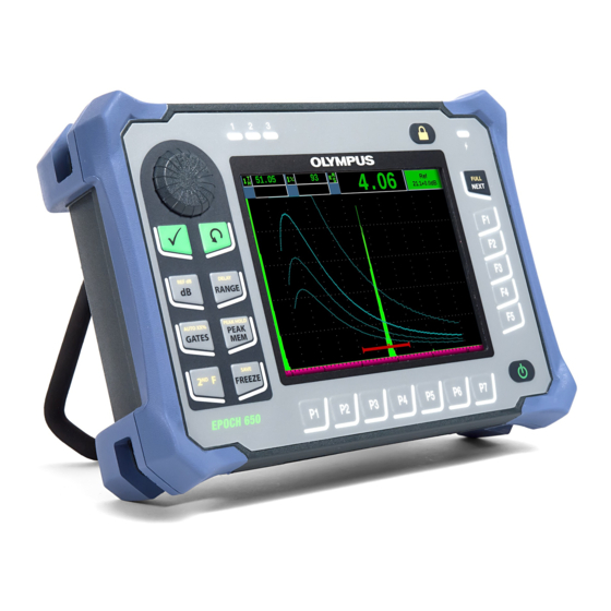
DMTA-10055-01EN, Rev. A, February 2015 Introduction The EPOCH 650 is a portable ultrasonic nondestructive test (NDT) instrument used to detect flaw conditions in welds, pipes, and many other structural and/or industrial materials. The instrument may be used in indoor and outdoor environments. This flaw detector offers advanced conventional ultrasonic performance. -
Page 28: Package Content
DMTA-10055-01EN, Rev. A, February 2015 Please thoroughly review this document with your EPOCH 650 in hand so that you can become familiar with the actual use of the instrument. Olympus recommends that all operators have a thorough understanding of the principles and limitations of ultrasonic nondestructive testing. -
Page 29: Figure I-4 Transport Case Contents
DMTA-10055-01EN, Rev. A, February 2015 Lock Figure i-4 Transport case contents For a list of optional accessories, see the parts list on page 331. Introduction... - Page 30 DMTA-10055-01EN, Rev. A, February 2015 Introduction...
-
Page 31: Hardware Overview
DMTA-10055-01EN, Rev. A, February 2015 1. Hardware Overview Figure 1-1 on page 19 and Figure 1-2 on page 20 show the EPOCH 650 ultrasonic flaw detector and identify its main components. D-rings (4) to attach the optional chest harness Protective rubber bumpers (4) -
Page 32: Front Panel
Figure 1-2 EPOCH 650 rear view Front Panel The EPOCH 650 front panel features a combination of direct-access keys, navigation arrows, dynamic function, and parameter access keys to optimize the usability of the instrument in any mode. The layout of the front panel provides direct access to common inspection parameters, and easy adjustment of values from either side of the instrument without obstructing the view of the display. -
Page 33: Figure 1-3 The Epoch 650 - Adjustment Knob Configuration
Adjustment knob Display window Check and Escape keys Function keys Direct access keys Power key Parameter keys Figure 1-3 The EPOCH 650 — Adjustment knob configuration Alarm indicators Power indicator Arrow keys Check and Display window Escape keys Direct access keys... -
Page 34: Adjustment Knob Configuration
DMTA-10055-01EN, Rev. A, February 2015 1.1.1 Adjustment Knob Configuration The adjustment knob configuration provides smooth value slewing (see Figure 1-6 on page 23). The adjustment knob is used along with the check key to adjust parameter values in either coarse or fine increments. The adjustment knob ( ) increases or decreases the value of a highlighted adjustable parameter. -
Page 35: Figure 1-6 The Epoch 650 - Adjustment Knob Configuration
DMTA-10055-01EN, Rev. A, February 2015 Adjustment knob Check and Escape keys Direct access keys Figure 1-6 The EPOCH 650 — Adjustment knob configuration Hardware Overview... -
Page 36: Figure 1-7 Knob Configuration (English And International Versions)
DMTA-10055-01EN, Rev. A, February 2015 In addition to the English, the EPOCH 650 is also offered with an international- symbol version of the adjustment knob configuration (see Figure 1-7 on page 24). Adjustment knob Check and Escape keys Direct access keys... -
Page 37: Navigation Pad Configuration
DMTA-10055-01EN, Rev. A, February 2015 The EPOCH 650 is also offered in Chinese and Japanese versions of the adjustment knob configuration (see Figure 1-8 on page 25). Adjustment knob Check and Escape keys Direct access keys NEXT/FULL key Figure 1-8 Knob configuration (Chinese and Japanese versions) 1.1.2... -
Page 38: Figure 1-9 The Epoch 650 - Navigation Pad Configuration
The direct access keys cause the software interface to jump directly to the associated parameter or activate a function (see “Direct-Access Keys” on page 28). Arrow keys Check and Escape keys Direct access keys Direct access keys Figure 1-9 The EPOCH 650 — Navigation pad configuration Chapter 1... -
Page 39: Figure 1-10 Pad Configuration (English And International Versions)
DMTA-10055-01EN, Rev. A, February 2015 The EPOCH 650 is also offered with an international-symbol version of the navigation pad configuration (see Figure 1-10 on page 27). Arrow keys Check and Escape keys Direct access keys Direct access keys NEXT/FULL key... -
Page 40: Direct-Access Keys
DMTA-10055-01EN, Rev. A, February 2015 The EPOCH 650 is also offered with Chinese and Japanese versions of the navigation pad configuration (see Figure 1-11 on page 28). Arrow keys Check and Escape keys Direct access keys Direct access keys NEXT/FULL key Figure 1-11 Pad configuration (Chinese and Japanese versions) 1.1.3... -
Page 41: Table 3 English Direct-Access Key Descriptions
DMTA-10055-01EN, Rev. A, February 2015 Table 3 English direct-access key descriptions Navpad Knob Function config. config. Adjusts system sensitivity. F, (REF dB) Locks the reference gain level and allows the scanning gain to be used. SAVE Saves to the selected File and ID (navigation pad configuration only). -
Page 42: Function And Parameter Keys
The function and parameter keys are identical in both appearance and function on both configurations of the EPOCH 650. Five function keys (F1 through F5) and seven parameter keys (P1 through P7) are located around the display (see Figure 1-12 on page 31). -
Page 43: Figure 1-12 Function And Parameter Keys
DMTA-10055-01EN, Rev. A, February 2015 Parameter lock key Function keys Parameter keys Figure 1-12 Function and parameter keys Hardware Overview... -
Page 44: Power Indicator
1.1.6 Alarm Indicators The EPOCH 650 ultrasonic flaw detector provides three alarm indicator lights (see Figure 1-15 on page 33). The indicators are located on the front panel above the display window (see Figure 1-3 on page 21 and Figure 1-4 on page 21). -
Page 45: Connectors
Olympus service center for a small charge. Selection of these transducer connections is based on operator preference. Both the BNC and LEMO 01 series connectors available are rated to IP67 for use in most inspection environments. The EPOCH 650 is illustrated with BNC connectors in this document. -
Page 46: Digital Out Connector
See “Input/Output Specifications” on page 305 for the complete specifications of the supported I/O signals. The Digital Out connector is located at the back of the EPOCH 650 (see Figure 1-17 on page 37). A rubber cover protects the connector. -
Page 47: Alarm Output Connector Pins
1.2.2.1 Alarm Output Connector Pins The EPOCH 650 includes three dedicated alarm outputs that allow you to control an external device based on an alarm condition. These outputs are combined with the Digital Out signals on the same connector (see Table 23 on page 305). Each alarm output is a 5V TTL digital signal that corresponds to the current alarm condition for each gate. -
Page 48: Trigger Input And Output Pins
The VGA Out connector is located at the back of the EPOCH 650 ultrasonic flaw detector (see Figure 1-17 on page 37). A rubber cover protects the connector. Using the VGA output, you can display the full contents of the EPOCH 650 screen on any device that accepts VGA input. -
Page 49: Usb Client Port And Microsd Card Slot
1.2.4 USB Client Port and microSD Card Slot The microSD card slot and USB port are located on the right side of the EPOCH 650 ultrasonic flaw detector. A protective cover has an integral membrane seal to keep out liquids (see Figure 1-18 on page 38). Two thumb screws on the protective cover allow quick access to the microSD slot and USB port without the need for tools. -
Page 50: Usb Client Port
1.2.4.1 USB Client Port The EPOCH 650 ultrasonic flaw detector comes standard with one USB port currently used for PC client communication. The USB client port allows one-way communication only. A peripheral device can pass commands to the EPOCH 650, but the EPOCH 650 cannot pass commands to a peripheral device. -
Page 51: Microsd Card Slot
DMTA-10055-01EN, Rev. A, February 2015 1.2.4.2 microSD Card Slot A 2 GB microSD card is included with every EPOCH 650, but most types and capacities of microSD cards can be used. To install the microSD memory card Remove the card from its packaging. -
Page 52: Battery Compartment
Membrane vent hole Figure 1-20 The battery compartment The EPOCH 650 ultrasonic flaw detector accepts one rechargeable lithium-ion battery pack (P/N: 600-BAT-L-3 [U8051431]) that can be recharged inside the instrument or on the optional external charging base (P/N: EPXT-EC-X). Chapter 1... -
Page 53: Instrument Stand
DMTA-10055-01EN, Rev. A, February 2015 Instrument Stand The EPOCH 650 ultrasonic flaw detector features an articulating pipe stand for variable viewing angles (see Figure 1-21 on page 41). The stand is attached to the back of the instrument with two hard pivot blocks, and has a high friction coating for resistance to sliding during use. - Page 54 DMTA-10055-01EN, Rev. A, February 2015 Chapter 1...
-
Page 55: Powering The Epoch 650
Whatever source is selected, the power on/off procedure is the same. To power on or off the EPOCH 650 Press the Power button to turn on the EPOCH 650 (see Figure 2-1 on page 43). Pressing this key once causes an initial beep, followed by the instrument startup screen. -
Page 56: Lithium-Ion Battery
The system beeps, then immediately shuts down. Lithium-Ion Battery The lithium-ion (Li-ion) battery is the primary method for powering the EPOCH 650. This battery comes installed in every instrument. When properly maintained, and when the instrument is operated under typical inspection conditions, the lithium-ion battery should provide between 15 and 16 hours of continuous operation. -
Page 57: Ac Charger/Adaptor
Connect the power cord to the charger/adaptor unit and to an appropriate power outlet (see Figure 2-2 on page 46). Use only the AC power cord supplied with the EPOCH 650. Do not use the supplied AC power cord with other products. -
Page 58: Figure 2-2 Connecting The Charger/Adaptor
AC power cord Figure 2-2 Connecting the charger/adaptor Lift the rubber seal that covers the AC charger/adaptor connector on top of the EPOCH 650 instrument. Connect the DC power plug to the DC adaptor connector (see Figure 2-3 on page 46). -
Page 59: Standalone Battery Charger
DMTA-10055-01EN, Rev. A, February 2015 Standalone Battery Charger The EPOCH 650 ultrasonic flaw detector battery can also be charged externally using the optional standalone battery charger (P/N: EPXT-EC-X). Charging a battery externally allows you to charge one battery while using another in the instrument. For more information about the external charger, contact Olympus or your local sales representative. - Page 60 DMTA-10055-01EN, Rev. A, February 2015 Table 4 EPOCH 650 power status indicators(continued) AC charger/adaptor AC power Battery/AC power indicator connected? Status indicator Green Li-ion b attery level as indicated by the black horizontal bar Chapter 2...
-
Page 61: Software Overview
Parameter buttons Figure 3-1 Software main display elements There are five groups of menus on the EPOCH 650. Each menu group is identified with a number (1/5, 2/5, 3/5, 4/5, and 5/5). The menu indicator, located in the lower- right corner of the software main display, shows which menu is currently selected (see Figure 3-1 on page 49). -
Page 62: Choosing A Function Menu Item
DMTA-10055-01EN, Rev. A, February 2015 NEXT key Figure 3-2 The menu groups and their level numbers Choosing a Function Menu Item The function menu item with a green background is the function that is selected. At startup, the first function menu item in each of the five menu groups is the default selection (see Figure 3-2 on page 50). -
Page 63: Parameter Selection
DMTA-10055-01EN, Rev. A, February 2015 Parameter Selection When a parameter button has a green background it is selected, and the corresponding function button remains green (see Figure 3-4 on page 51). Currently selected function Currently selected parameter Figure 3-4 The focus is on the selected parameter (green) To select a parameter ... -
Page 64: Convention For Identifying Menu Items And Parameters
DMTA-10055-01EN, Rev. A, February 2015 Figure 3-5 P3 key selecting the Range parameter Convention for Identifying Menu Items and Parameters The following convention is used to concisely refer to an element in the menu structure: Menu > Parameter = value where: Menu represents the name of the menu item (example: Meas Setup) Parameter represents the name of the parameter (example: Unit) -
Page 65: Escape Key
DMTA-10055-01EN, Rev. A, February 2015 • The Up and Down arrow keys ( ) make coarse adjustments to the value of a highlighted adjustable parameter. The Left and Right arrow keys ( ) make fine adjustments. • The adjustment knob turns clockwise or counterclockwise to increase or decrease a parameter value. -
Page 66: Auto Xx% Feature
DMTA-10055-01EN, Rev. A, February 2015 Lock Figure 3-6 Adjustment knob configuration — Lock key AUTO XX% Feature Pressing 2 F, (AUTO XX%) activates the AUTO XX% feature, which automatically adjusts the gain in order to set the gated echo amplitude to XX% of full screen height (the default XX value is 80 %). -
Page 67: Pulser And Receiver Settings
DMTA-10055-01EN, Rev. A, February 2015 Pulser and Receiver Settings The EPOCH 650 allows access to most of its pulser and receiver settings through the Pulser and the Rcvr menus. System sensitivity (gain) and reference gain are controlled exclusively using the direct-access keys. -
Page 68: Pulser
Figure 3-8 The reference and scanning gains 3.9.3 Pulser The EPOCH 650 main pulser functions are accessible by choosing the Pulser menu. Each individual pulser parameter is displayed above the parameter keys, and can be adjusted by pressing the corresponding parameter key. -
Page 69: Table 5 Filter Cutoffs
• Reject: Percent reject (from 0 % to 80 %) The 30 filters available on the EPOCH 650 allow broadband or narrowband settings to match the requirements of a given application. Each filter is a fully digital filter set. Table 5 on page 57 lists the low-pass and high-pass cutoffs for each available filter. -
Page 70: 3.10 Gates
DMTA-10055-01EN, Rev. A, February 2015 3.10 Gates The EPOCH 650 features two standard independent measurement gates and one optional independent measurement gate. Gate 1 and gate 2 are the standard measurement gates. The Interface Gate is an optional measurement gate principally used in immersion applications (see “Interface Gate”... -
Page 71: Gate 1 And Gate 2
DMTA-10055-01EN, Rev. A, February 2015 3.10.2 Gate 1 and Gate 2 Both Gate 1 and Gate 2 menus allow access to specific gate positioning and alarm functions. When either menu is selected, the following parameters become visible above the parameter keys. •... -
Page 72: Figure 3-10 Trigger In Edge And Peak Modes
DMTA-10055-01EN, Rev. A, February 2015 • G2 Mode/G2 RF/G2 %Amp: Same settings as above, but for gate 2 only. • G2 Tracks: Toggles tracking mode of gate 2 with respect to gate 1 on or off. Tracking ON is considered true echo-to-echo measurement mode. Gate measurement modes, selected by G1 Mode or G2 Mode, determine which gated echo or echo parameters triggers a digital measurement. -
Page 73: Gate Alarm Indications
Whenever an alarm is triggered on either measurement gate, you are alerted in two different ways: • The EPOCH 650 emits an audible tone • One of two alarm indicators (LEDs) is illuminated on the instrument front panel (see Figure 3-12 on page 61). -
Page 74: 3.11 Calibration
(see “Alarm Outputs” on page 137). 3.11 Calibration The EPOCH 650 can be easily calibrated for both zero offset and velocity in order to provide accurate thickness (sound path) measurements from indications. The EPOCH 650 utilizes an auto-calibration system for a simple, two-point approach. -
Page 75: Figure 3-13 The Auto Cal Menu
DMTA-10055-01EN, Rev. A, February 2015 Figure 3-13 The Auto Cal menu Select the Type parameter, then select the appropriate calibration type (Thickness for straight beam or Soundpath for angle beam are the most common). Select Cal-Zero. Adjust the displayed value to the appropriate thickness. For this example, the transducer is coupled to a 5 mm (0.200 in.) step (see Figure 3-14 on page 64). -
Page 76: Figure 3-14 The Cal-Zero Value
DMTA-10055-01EN, Rev. A, February 2015 Figure 3-14 The Cal-Zero value Select Continue to accept the adjusted value, and then move on to the second calibration step. Couple the transducer to the thick step of material. 10. Position gate 1 around the resulting indication on screen. 11. -
Page 77: Figure 3-15 The Gate 1 Start
DMTA-10055-01EN, Rev. A, February 2015 Figure 3-15 The gate 1 start 12. Select Cal-Vel. 13. Use the knob or arrow keys to adjust the displayed value to the appropriate thickness. For this example, the transducer is coupled to a 12.5 mm (0.500 in.) step (see Figure 3-16 on page 66). -
Page 78: Figure 3-16 The Velocity Cal Value
DMTA-10055-01EN, Rev. A, February 2015 Figure 3-16 The Velocity Cal value 14. Select Done to accept the adjusted value and complete the calibration process. 15. Press RANGE, and then adjust the screen range to the desired setting (see Figure 3-17 on page 66). Figure 3-17 The Range value Chapter 3... -
Page 79: Angle Beam Calibration
DMTA-10055-01EN, Rev. A, February 2015 3.11.2 Angle Beam Calibration Angle beam calibrations typically require four steps. To perform an angle beam calibration Locate the Beam Index Point (see “Locating the Beam Index Point” on page 165). Verify the refracted angle of wedge (see “Verifying the Refracted Angle” on page 167). -
Page 80: 3.12 Data Logger
“Data Logger” on page 187. 3.12.1 Calibration Files To setup and save a calibration file on the EPOCH 650, first complete all ultrasonic and software setups that will be saved within the calibration. To create and store a calibration file Select the File menu item. -
Page 81: Figure 3-19 The Create Screen With Virtual Keypad
DMTA-10055-01EN, Rev. A, February 2015 Figure 3-19 The Create screen with virtual keypad Press NEXT to complete the file naming process. For creation of an incremental (Inc) file, you must first create a Start Point. Press NEXT until the Create button is highlighted. 10. -
Page 82: Resetting The Instrument
3.12.2 Resetting the Instrument The EPOCH 650 allows you to reset its current settings to default values. This capability is useful if you want to reset the instrument parameters, delete all the data logger files, or reset the instrument back to its factory settings. -
Page 83: Figure 3-21 The Resets Page
DMTA-10055-01EN, Rev. A, February 2015 Use the arrow keys or the adjustment knob to highlight a reset type and press Select (P1 key). Available reset types are: • Parameters reset Resets only the current on-screen parameters to system default values (does not affect saved files). - Page 84 DMTA-10055-01EN, Rev. A, February 2015 Chapter 3...
-
Page 85: Software Interface
DMTA-10055-01EN, Rev. A, February 2015 4. Software Interface The EPOCH 650 software main display is shown in Figure 4-1 on page 73. File name File ID number Measurement Basic parameters reading boxes Flag Live A-scan view Menu buttons Gate 2 (blue) -
Page 86: Button Types
Measurement reading boxes Gain setting Figure 4-2 Software display elements in full screen mode Button Types Table 6 on page 74 shows the various types of buttons found in the EPOCH 650 ultrasonic flaw detector interface. Table 6 Button types Type... -
Page 87: File Identifier And Message Bars
DMTA-10055-01EN, Rev. A, February 2015 Table 6 Button types (continued) Type Example Description Submenu Function menu item that opens a dialog box or a screen with more parameters. Editable value Parameter with an editable value. Turn the adjustment knob or press the arrow keys to change the value. -
Page 88: Direct-Access Parameters
DMTA-10055-01EN, Rev. A, February 2015 Direct-Access Parameters Direct-access parameters always appear at the top right corner of the display window. This allows you to view these parameters from the main screen regardless of which menu or parameter you are currently accessing. These parameters include Gain, Range, Delay, and Gates. -
Page 89: Measurement Reading Boxes
DMTA-10055-01EN, Rev. A, February 2015 RANGE direct access key is active RANGE preset values displayed over parameter keys Figure 4-6 Direct access preset values Measurement Reading Boxes The measurement reading boxes at the top-left corner of the software main display present the icons and digital values for up to five selectable measurements (see Figure 4-7 on page 77). -
Page 90: Live-Scan Area
Figure 4-8 Example of an A-scan waveform with gates Flags The EPOCH 650 ultrasonic flaw detector indicates when particular functions are active by displaying a set of flags, in a thin vertical area on the right of the live-scan area (see Figure 4-9 on page 79). Table 7 on page 79 provides a description of the possible flags. -
Page 91: Figure 4-9 The Area Displaying Flags
DMTA-10055-01EN, Rev. A, February 2015 Flag area Figure 4-9 The area displaying flags Table 7 Flag description Flag Description Length units are inches Length units are millimeters Length units are microseconds Indicates that the 2 F key has been pressed. Gate 1 is in peak measurement mode. - Page 92 DMTA-10055-01EN, Rev. A, February 2015 Table 7 Flag description (continued) Flag Description Gate 1 is in edge (or flank) measurement mode. Gate 2 is in edge (or flank) measurement mode. Gate 1 is in first-peak measurement mode. Gate 2 is in first-peak measurement mode. The IF gate is in J-Flank measurement mode.
- Page 93 DMTA-10055-01EN, Rev. A, February 2015 Table 7 Flag description (continued) Flag Description Calibration is active. Curved surface correction (CSC) is active. B-scan is active. Gate tracking (Echo-to-Echo) is active. Zoom is active. FREEZE is active. Auto FREEZE is active. PEAK MEM is active. (PEAK HOLD) reference echo is active.
-
Page 94: Menu Contents
Indicates that the instrument is running off of battery power. Indicates that video record mode is actively acquiring a video. Menu Contents The EPOCH 650 ultrasonic flaw detector uses menus to categorize similar functions. It includes five menu groups shown in Figure 4-10 on page 83. Chapter 4... -
Page 95: Figure 4-10 Standard Menu Groups
DMTA-10055-01EN, Rev. A, February 2015 Figure 4-10 Standard menu groups Table 8 on page 83 to Table 12 on page 85 provides a quick reference of available menus and parameters for each menu group. Table 8 Content of the first menu group Menus Parameters Basic... -
Page 96: Table 9 Content Of The Second Menu Group
DMTA-10055-01EN, Rev. A, February 2015 Table 9 Content of the second menu group Menus Parameters Gate 1 Zoom Start Width Level Alarm Min Depth Status (only when Alarm is set to Min Depth) Gate 2 Zoom Start Width Level Alarm Min Depth Status (only when... -
Page 97: Table 12 Content Of The Fifth Menu Group
DMTA-10055-01EN, Rev. A, February 2015 Table 11 Content of the fourth menu group (continued) Menus Parameters DGS/AVG Ref (setup Reg Level ACV Spec G1Start Setup mode) (inspect (inspect Delta VT mode) mode) (inspect mode) Ref B Scan dB Ref Level G1Start Setup (inspect... -
Page 98: Setup
Setup Pages The EPOCH 650 ultrasonic flaw detector software includes a number of setup pages allowing you to adjust instrument features and parameters to your preferences. The Display setup page shown in Figure 4-11 on page 87, is an example of a setup page. -
Page 99: Entering An Alphanumeric Value Using The Virtual Keyboard
DMTA-10055-01EN, Rev. A, February 2015 Title bar Currently selected parameter Available values for the selected parameter Figure 4-11 The Display setup page and its elements A title bar identifies the type of setup page. Parameters appear with the parameter label on the left and its current value and units (if applicable) on the right. Seven button fields at the bottom of the page may contain available values for the currently selected parameter. -
Page 100: Figure 4-12 The Edit Page With Its Virtual Keyboard
DMTA-10055-01EN, Rev. A, February 2015 To enter an alphanumeric value using the virtual keyboard Access a setup page that contains parameters with alphanumeric values (see the example of Figure 4-12 on page 88). Figure 4-12 The Edit page with its virtual keyboard Select the field that you want to edit using the NEXT button, and then choose Edit. -
Page 101: Display Setup Page
DMTA-10055-01EN, Rev. A, February 2015 4.8.2 Display Setup Page The Display setup page allows you to set parameters that control aspects of the display (see Figure 4-13 on page 89). Figure 4-13 The Display setup page To use the Display setup page Choose Display Setup (group 3/5). - Page 102 DMTA-10055-01EN, Rev. A, February 2015 NOTE Envelope drawing mode is always opposite the selected Live A-Scan drawing mode. • X-Axis Grid Mode Sets the horizontal X-axis grid display mode — Off: no grid — Standard: 10 divisions spaced evenly and labeled 1 to 10 —...
-
Page 103: Grid Setup Page
DMTA-10055-01EN, Rev. A, February 2015 — Outdoor Y: yellow background, blue text — Mono: Black background, white text Press to return to the live screen. 4.8.3 Grid Setup Page The Grid setup page allows you to activate and set up the Grid View feature for visualization of data collection in the live A-scan screen. -
Page 104: Figure 4-15 Example Of Measurement Reading Boxes With Icons
DMTA-10055-01EN, Rev. A, February 2015 To use the Reading setup page Choose Meas Setup (group 3/5). Press Reading Setup (P1 key). Select the parameter you want to set up. • Reading Selection Sets the measurement reading box mode. — Auto: Automatically makes the selection based on instrument function —... -
Page 105: Table 13 Available Measurement Readings
DMTA-10055-01EN, Rev. A, February 2015 Table 13 Available measurement readings (continued) Icon Measurement reading Description Gate 1 Depth to Reflector Depth to reflector in gate 1. Used with Angle. Gate 2 Depth to Reflector Depth to reflector in gate 2. Used with Angle. - Page 106 DMTA-10055-01EN, Rev. A, February 2015 Table 13 Available measurement readings (continued) Icon Measurement reading Description Gate 2 Maximum Amplitude Maximum amplitude in gate 2. Resets on gate adjustment and on most pulser/receiver adjustments. Gate 1 Minimum Amplitude Minimum amplitude in gate 1. Resets on gate adjustment and on most pulser/receiver adjustments.
-
Page 107: General Setup Page
DMTA-10055-01EN, Rev. A, February 2015 Table 13 Available measurement readings (continued) Icon Measurement reading Description AWS B AWS reference indication value B. AWS C AWS sound path correction value C. Gate1 Ref dB-Current Amp Comparison value in dB measuring the difference between the gate 1 echo height and the reference gain. -
Page 108: Figure 4-16 The General Setup Page
DMTA-10055-01EN, Rev. A, February 2015 Figure 4-16 The General Setup page To use the General setup page Choose Inst Setup (group 3/5). Press General (P1 key). Select the parameter you want to set up: • Language Used to select the user interface language (English, Japanese, German, French, Spanish, Russian, and Chinese). - Page 109 • Communications Protocol Used to select command type for remote/PC communication with the instrument (Multi Char or Single Char). When communication with the Olympus GageView Pro PC software, Multi Character mode must be selected. • Communications Device Used to select the type of remote/PC communication (USB or RS-232). When communication with the Olympus GageView Pro PC software, USB mode must be selected.
-
Page 110: About Page
DMTA-10055-01EN, Rev. A, February 2015 — Off Press to return to the live screen. 4.8.6 About Page The About page provides information about the instrument hardware and software identification data (see Figure 4-17 on page 98). Figure 4-17 The Status setup page The About page has four sub-pages: •... -
Page 111: Clock Setup Page
DMTA-10055-01EN, Rev. A, February 2015 Allows you to upgrade the EPOCH 650 system software. See “Maintenance and Troubleshooting” on page 297 for more information on upgrading your EPOCH 650 instrument software. 4.8.7 Clock Setup Page The Clock setup page, shown in Figure 4-18 on page 99, allows you to configure the date and time settings for the instrument. -
Page 112: Software Options Setup Page
The Software Options page allows you to enter an activate code to allow access to a software option not included with the standard package of instrument features. This is provided by an Olympus representative after the purchase of a particular software option. See “Defining Licensed and Unlicensed Software Features” on page 225 for details on software option activation. - Page 113 Restores all data logger files and live instrument settings from the microSD card to internal memory from a previously backed up file. IMPORTANT Restore permanently overwrites all existing data on the EPOCH 650 with data from the microSD card. Software Interface...
-
Page 114: Editable Parameters Page
DMTA-10055-01EN, Rev. A, February 2015 Figure 4-19 Misc setup page NOTE The Debug button (P6 key) is intended for use by an authorized Olympus service center or customer service representative only. 4.8.10 Editable Parameters Page The Editable Parameters page allows you to customize preset values for direct access keys or coarse adjustment lists (see Figure 4-20 on page 103). -
Page 115: Figure 4-20 Editable Parameters Setup Page
DMTA-10055-01EN, Rev. A, February 2015 • Pulser Frequency • Trigger Angle • Basic Velocity • Trigger Thickness • Trigger X value See “Parameter Adjustment” on page 52 for information on using the navigation pad or adjustment knob. The Editable Parameters setup page displays all the system parameters that can be edited. -
Page 116: Analog Output Setup Page
DMTA-10055-01EN, Rev. A, February 2015 Use the adjustment knob or arrow keys to change the value of the selected parameter value. To erase the value of a selected parameter, press Clear (P1 key). 4.8.11 Analog Output Setup Page The analog output setup parameters are located in the A-Out setup page. See “Analog Output”... -
Page 117: Adjusting The Pulser/Receiver
The AUTO XX% feature was formerly known as the AUTO-80 % in the EPOCH 4 Series. The default setting for AUTO XX% in the EPOCH 650 ultrasonic flaw detector is 80 % full-screen height (FSH). You can adjust the FSH target value to meet the demands of the application. -
Page 118: Setting Reference Gain And Scanning Gain
DMTA-10055-01EN, Rev. A, February 2015 You can use the AUTO XX% feature to bring an echo to XX% FSH in any gate. To use AUTO XX% feature Press GATES to select the gate that measures the echo to be adjusted. Press 2 F, (AUTO XX%) to activate the AUTO XX% feature. -
Page 119: Pulser Adjustments
PRF rate to assure that small defects are detected as the probe moves along the part. The EPOCH 650 allows you to manually adjust the PRF from 10 Hz to 2000 Hz in 50 Hz (coarse) or 10 Hz (fine) increments. The instrument also has two Auto-PRF settings to automatically adjust the PRF based on screen range. -
Page 120: Pulse Energy (Voltage)
5.4.2 Pulse Energy (Voltage) The EPOCH 650 ultrasonic flaw detector can adjust the pulse energy from 0 V to 400 V in increments of 100 V. With this flexibility, you can set the pulse energy from to a minimum when you want to extend the battery life, or provide a very high power pulser for the most difficult materials. -
Page 121: Damping
The damping control allows you to optimize the waveform shape for high resolution measurements using an internal resistive circuit. There are four damping settings on the EPOCH 650 ultrasonic flaw detector: 50 Ω, 100 Ω, 200 Ω, or 400 Ω. To adjust the Damping ... -
Page 122: Pulser Type
Choose Pulser > Mode, and then vary the setting. 5.4.5 Pulser Type The EPOCH 650 operates in two pulser modes that you can select using the Pulser parameter of the Pulser mode: Spike Used to mimic a traditional spike pulse by using a narrow-width pulse to excite the transducer. -
Page 123: Pulser Frequency Selection (Pulse Width)
DMTA-10055-01EN, Rev. A, February 2015 5.4.6 Pulser Frequency Selection (Pulse Width) The pulser frequency selection sets the pulse width when Pulser > Pulser = Square. This frequency selection allows you to tune the shape and duration of each pulse to obtain the best performance from the transducer being used. -
Page 124: Table 14 Advanced Filters
1.5 MHz–8.5 MHz • 5.0 MHz–15.0 MHz • 8.0 MHz–26.5 MHz The EPOCH 650 contains the following 23 Advanced filters which are not tested in accordance with EN12668-1:2010 (see Table 14 on page 112). Table 14 Advanced filters 10 MHz 1.2 MHz 4.0 MHz... -
Page 125: Waveform Rectification
DMTA-10055-01EN, Rev. A, February 2015 5.5.2 Waveform Rectification The EPOCH 650 ultrasonic flaw detector can operate in one of four different rectification modes that you can select using the Rcvr > Rect parameter: Full, Half+, Half-, or RF (unrectified). The RF mode is not active while operating in special software feature modes, such as DAC mode or Peak Memory. - Page 126 DMTA-10055-01EN, Rev. A, February 2015 Chapter 5...
-
Page 127: Managing Special Waveform Functions
DMTA-10055-01EN, Rev. A, February 2015 6. Managing Special Waveform Functions This chapter describes how to manage special waveform functions of the EPOCH 650 ultrasonic flaw detector. Reject The Rcvr > Reject parameter allows you to eliminate unwanted, low-level signals from the display. The reject function is linear and adjustable from 0 % to 80 % FSH. -
Page 128: Peak Memory
DMTA-10055-01EN, Rev. A, February 2015 Reject level line Figure 6-1 Horizontal line indicating the reject level Peak Memory The peak memory function enables the display to capture and store on the screen the amplitude of each A-scan acquisition. The display updates each pixel if a signal of greater amplitude is acquired. -
Page 129: Figure 6-2 Peak Memory Signal Envelope Example
DMTA-10055-01EN, Rev. A, February 2015 Current live waveform (green line) Peak memory signal envelope (blue area) Peak memory flag Figure 6-2 Peak memory signal envelope example This function is useful when it is necessary to find the peak from an indication during an angle beam inspection. -
Page 130: Peak Hold
The freeze function holds, or freezes, the information on the screen at the moment at the moment it is activated. Once the freeze function is activated, the pulser/receiver of the EPOCH 650 ultrasonic flaw detector becomes inactive and does not acquire any further data. A freeze ( ) symbol appears on the right side of the screen indicating that the function is active. -
Page 131: Grid Modes
Range (cannot be increased) • Pulser/Receiver settings such as PRF, Energy, Mode, pulser waveform, and Filter Grid Modes The EPOCH 650 ultrasonic flaw detector provides multiple grid modes for easy A- scan interpretation, depending on the application. Managing Special Waveform Functions... -
Page 132: Figure 6-3 Selecting The X-Axis Grid Mode
DMTA-10055-01EN, Rev. A, February 2015 To adjust the grid modes Select Display Setup > Display Setup to open the Display setup menu. Press NEXT to move the focus to the X-Axis Grid Mode parameter (see Figure 6-3 on page 120). Figure 6-3 Selecting the x-axis grid mode Use the adjustment knob or keypad to select the desired x-axis grid mode (see Figure 6-4 on page 121). -
Page 133: Figure 6-4 The X-Axis Grid Modes
DMTA-10055-01EN, Rev. A, February 2015 Standard grid: traditional flaw detector view with 10 divisions equally spaced across the screen range, and the numbers 1–10 appearing below each division. Sound Path grid: displaying actual sound path measurements at equally spaced increments along the horizontal axis. -
Page 134: Baseline Break
DMTA-10055-01EN, Rev. A, February 2015 100 % (zero % to 100 % (zero % to 100 % scale) 110 % scale) Figure 6-5 The y-axis grid modes: 100 % (left), 110 % (right) Baseline Break The baseline break feature modifies the appearance of the A-scan in full wave rectified mode. -
Page 135: Gates
In the EPOCH 650, gate 1 appears as a solid red line while gate 2 appears as a hollow blue line. -
Page 136: Figure 7-2 The Gate 1 Menu
DMTA-10055-01EN, Rev. A, February 2015 Both gates can be used to take thickness measurements with straight-beam transducers, sound path and depth measurements with angle beam transducers, measure signal amplitude, measure time-of-flight in microseconds, or to trigger threshold and minimum-depth alarms. The gates can also be used together to take echo-to-echo thickness measurements. -
Page 137: Quickly Adjusting Basic Gate Parameters
DMTA-10055-01EN, Rev. A, February 2015 Alarm Used to select a gate alarm condition (see “Gate Alarms” on page 133 for details). AFreeze Visible only when Alarm is Positive or Negative. Activates or deactivates the Auto Freeze function (for more information, see “Freeze” on page 118). Min Depth Used to adjust the minimum depth value which triggers a minimum depth alarm. -
Page 138: Gate Measurement Modes
Gate Measurement Modes The EPOCH 650 ultrasonic flaw detector’s two gates provide measurements of a gated indication based on one of four possible measurements modes. You can define the measurement mode of each gate in the Gate Setup menu (shown in Figure 7-4 on page 127). -
Page 139: Figure 7-4 The Gate Setup Menu
DMTA-10055-01EN, Rev. A, February 2015 Figure 7-4 The Gate Setup menu When a measurement is in progress using one of the measurement gates, a small triangle appears on the gate to indicate from which echo/point the measurement is being acquired (see Figure 7-5 on page 128 and Figure 7-6 on page 129). The available parameters are: G(1,2) Mode Each gate can make measurements using the following modes:... -
Page 140: Figure 7-5 Trigger Indicator On Gate In Edge And Peak Modes
DMTA-10055-01EN, Rev. A, February 2015 J-Flank Acquires thickness measurement readings based on the position of the first crossing point of a gated signal and amplitude measurement readings from the highest peak of the first echo in the gated region (see Figure 7-6 on page 129) Peak Edge... -
Page 141: Figure 7-6 Trigger Indicator On Gate In 1Stpeak, And J-Flank Modes
DMTA-10055-01EN, Rev. A, February 2015 1st Peak J-Flank Figure 7-6 Trigger indicator on gate in 1stPeak, and J-Flank modes G(1,2) RF In unrectified (RF) mode, used to choose the polarity of the gate. Options include: Dual The gate appears in the positive and negative side of the X-axis. Position and width are identical, and the gate level mirrors across the X-axis (example: 25 % and –25 %). -
Page 142: Viewing Measurement Readings
“Reading Setup Page” on page 91. Gate Tracking and Echo-to-Echo Measurements The gate tracking feature of the EPOCH 650 ultrasonic flaw detector allows you to make echo-to-echo measurements whenever this feature is required by an application. Echo-to-echo measurements can be made between gate 2 —gate 1. -
Page 143: Figure 7-7 Echo-To-Echo Measurement Example
DMTA-10055-01EN, Rev. A, February 2015 Gate tracking maintains a constant separation between the position of the indication in the first gate and the start position of the second gate. With this dynamic mobility, the tracking gate is always positioned where you want to measure other indications. When gate tracking is active, the start position value of the tracking gate (the second gate involved in the measurement) defines the separation between the gates, not a fixed start position. -
Page 144: Operating In Time-Of-Flight Mode
Zooming on a Gate The EPOCH 650 ultrasonic flaw detector allows you to quickly zoom the screen range to provide fine resolution of a particular inspection zone. Using zoom, the instrument automatically uses screen delay to bring the point that corresponds to the gate start to the left side of the screen and adjusts the displayed range to match the gate width. -
Page 145: Gate Alarms
(see Figure 7-8 on page 134). All alarm conditions are stored in the EPOCH 650 data logger when the gate alarm is active and triggered at the time of file storage. All saved IDs with an active alarm display A1 for gate 1 alarm, A2 for gate 2 alarm, or AIF for interface gate alarm. -
Page 146: Minimum Depth Alarm
7.8.2 Minimum Depth Alarm The EPOCH 650 ultrasonic flaw detector is equipped with a minimum depth alarm that is triggered whenever the current thickness measurement reading falls below an operator-defined level. The minimum depth alarm can be used either with a single gate or in echo-to-echo measurement mode. -
Page 147: Minimum Depth Alarm With Gate Tracking
7.8.4 Minimum Depth Alarm with Gate Tracking The EPOCH 650 ultrasonic flaw detector can use the minimum-depth alarm when making echo-to-echo thickness measurements with gate tracking. When gate tracking is active, the tracking gate moves side-to-side, tracking the position of the echo in the non-tracking (first) gate. - Page 148 DMTA-10055-01EN, Rev. A, February 2015 Chapter 7...
-
Page 149: Programmable Inputs And Outputs
Alarm Outputs The EPOCH 650 includes three dedicated alarm outputs that allow you to control an external device based on an alarm condition (see Table 23 on page 305). Each alarm output is a 5 V TTL digital signal that corresponds to the current alarm condition for each gate. -
Page 150: Trigger Inputs And Outputs
Choose the Meas Setup > Special (group 3/5) menu, and select Trigger Mode. Adjust the trigger mode to the desired setting. When in Single mode, the EPOCH 650 does not send a pulse to the connected transducer(s) until the Check key ( ) is pressed (or through remote commands via the Digital Out or USB connector). -
Page 151: Encoder Inputs
The information is output as a scaled voltage, on either a 0–1 V or 0–10 V scale. The EPOCH 650 is connected to the external device by means of the analog output LEMO 00 connector on the top of the instrument. Each scaled voltage is output at full PRF rate up to 2 kHz. - Page 152 Used to select the value for the impedance of the peripheral device measuring the analog output of the EPOCH 650 instrument. Matching the impedance of the output from the EPOCH 650 with the impedance of the input to the peripheral device allows the instrument to properly offset the analog output to produce predictable output voltages based on screen measurements.
-
Page 153: Figure 8-1 The A-Out Setup Page
DMTA-10055-01EN, Rev. A, February 2015 Figure 8-1 The A-Out setup page Programmable Inputs and Outputs... - Page 154 DMTA-10055-01EN, Rev. A, February 2015 Chapter 8...
-
Page 155: Calibration
DMTA-10055-01EN, Rev. A, February 2015 9. Calibration Calibrating the EPOCH 650 ultrasonic flaw detector is the process of adjusting the unit so that it measures accurately on a particular material, using a particular transducer at a particular temperature. In calibrating the instrument, you set the zero offset and velocity parameters. The zero offset (sometimes referred to as probe delay) is set to compensate for the dead time between the firing of the main pulse and the entry of the sound into the test piece. -
Page 156: Calibration Modes
For more information on pulser and receiver adjustments, see “Pulser Adjustments” on page 107 and “Receiver Adjustments” on page 111. Use the auto measurement reading selection feature so that the EPOCH 650 automatically displays relevant thickness/sound path measurements during calibration based on the instrument settings. For more information, see “Reading Setup Page”... -
Page 157: Straight Beam Modes
Typically, these depth measurements are made from side-drilled holes of equal size. For accurate measurements, you must first verify the refracted angle of the transducer, as the EPOCH 650 calculates depth values based on sound path and known refracted Calibration... -
Page 158: Calibrating With A Straight Beam Transducer
0.100 in., 0.200 in., 0.300 in., 0.400 in., and 0.500 in. If the EPOCH 650 is set to work in metric units, the calibration process is exactly the same, except that the entries are in millimeters rather than inches. -
Page 159: Figure 9-1 Example Of A Gated Signal For Zero Calibration
DMTA-10055-01EN, Rev. A, February 2015 Press dB, and then adjust the gain value so that the echo amplitude is at approximately 80 %. The AUTO XX% feature automatically adjusts the gain to set the gated echo amplitude to XX% of full screen height (the default XX value is 80 %). To activate this feature, press 2 F, (AUTO XX%). -
Page 160: Figure 9-2 Entering The Zero Cal Thickness Value
DMTA-10055-01EN, Rev. A, February 2015 Figure 9-2 Entering the Zero Cal thickness value Adjust the value to match the known thickness of the gated indication (0.200 in. in this example), and then press Continue (P3 key) to continue to the second calibration step (see Figure 9-3 on page 149). -
Page 161: Figure 9-3 Example Of A Gated Signal For Velocity Calibration
DMTA-10055-01EN, Rev. A, February 2015 Figure 9-3 Example of a gated signal for velocity calibration Couple the transducer to the thick calibration block step. In this example, the transducer is coupled to the 0.500 in. step. 10. Use the GATES key to position gate 1 so that the first back-wall echo from the known thickness step exceeds the gate threshold. -
Page 162: Calibrating With A Delay Line Transducer
(the appropriate multiple of the first back-wall echo) during the velocity portion of the calibration. Calibrating with a Delay Line Transducer The sample delay line calibration described below is performed using Olympus transducer part number V202-RM, with a frequency of 10.0 MHz and an element diameter of 6 mm (0.25 in.). - Page 163 0.100 in., 0.200 in., 0.300 in., 0.400 in., and 0.500 in. If the EPOCH 650 is set to work in metric units, the calibration process is exactly the same, except that the entries are in millimeters rather than inches.
-
Page 164: Figure 9-5 Adjusting Zero Offset For The First Delay Line Echo
DMTA-10055-01EN, Rev. A, February 2015 Figure 9-5 Adjusting zero offset for the first delay line echo Select Auto Cal > Type = Thickness. Couple the transducer to the thin calibration block step. For this example, the transducer is coupled to the 0.100 in. step. Use the G1Start button (P5 key) to position gate 1 so that the first back-wall echo from the known thickness step exceeds the gate threshold. -
Page 165: Figure 9-6 Example Of A Gated Signal For Zero Calibration
DMTA-10055-01EN, Rev. A, February 2015 Thickness measurement Figure 9-6 Example of a gated signal for zero calibration Ensure that it is the first back-wall echo being gated, not a multiple echo from the end of the delay line tip. 10. Once a steady reading is achieved, choose Auto cal > Cal-Zero. The screen freezes and the Cal-Zero box appears (see Figure 9-2 on page 148). -
Page 166: Figure 9-7 Entering The Zero Cal Thickness Value
DMTA-10055-01EN, Rev. A, February 2015 Figure 9-7 Entering the Zero Cal thickness value 11. Adjust the value to match the known thickness of the gated indication (0.100 in. in this example), and then press Continue (P3 key) to continue to the second calibration step (see Figure 9-8 on page 155). -
Page 167: Figure 9-8 Example Of A Gated Signal For Velocity Calibration
DMTA-10055-01EN, Rev. A, February 2015 Figure 9-8 Example of a gated signal for velocity calibration 12. Couple the transducer to the thick calibration block step. In this example, the transducer is coupled to the 0.500 in. step. 13. Use the G1Start button (P5 key) to position gate 1 so that the first back-wall echo from the known thickness step exceeds the gate threshold. -
Page 168: Calibrating On A Single Test Block Of Known Thickness
(2, 3, 4, etc. multiple of the first back-wall echo) during the velocity portion of the calibration. Calibrating with a Dual Element Transducer The sample dual element calibration described below is performed using an Olympus transducer part number DHC711-RM with a frequency of 5.0 MHz and an element diameter of 6 mm (0.25 in.). - Page 169 It has steps measuring 0.100 in., 0.200 in., 0.300 in., 0.400 in., and 0.500 in. If the EPOCH 650 is set to work in metric units, the calibration process is exactly the same, except that the entries are in millimeters rather than inches.
-
Page 170: Figure 9-10 Example Of A Gated Signal For Zero Calibration
DMTA-10055-01EN, Rev. A, February 2015 Select Auto Cal > Type = Thickness. Couple the transducer to the thin calibration block step. For this example, the transducer is coupled to the 0.100 in. step. As noted above, a higher gain setting is required to produce a clean leading edge of the signal. Do not be concerned with the jagged peaks of the echo. -
Page 171: Figure 9-11 Entering The Zero Cal Thickness Value
DMTA-10055-01EN, Rev. A, February 2015 Figure 9-11 Entering the Zero Cal thickness value 11. Adjust the value to match the known thickness of the gated indication (0.100 in. in this example), and then choose Continue to continue to the second calibration step. -
Page 172: Figure 9-12 Example Of A Gated Signal For Velocity Calibration
DMTA-10055-01EN, Rev. A, February 2015 Figure 9-12 Example of a gated signal for velocity calibration 12. Couple the transducer to the thick calibration block step. In this example, the transducer is coupled to the 0.500 in. step. 13. Use the G1Start button (P5 key) to position gate 1 so that the first back-wall echo from the known thickness step exceeds the gate threshold. -
Page 173: Calibrating In Echo-To-Echo Mode
For this example, we are using Olympus standard 5-step steel-test block, part number 2214E. The steps measure 0.100 in., 0.200 in., 0.300 in., 0.400 in., and 0.500 in. - Page 174 DMTA-10055-01EN, Rev. A, February 2015 If the EPOCH 650 is set to work in metric units, the calibration process is exactly the same, except that the entries are in millimeters rather than inches. To calibrate in echo-to-echo mode using a delay line transducer Follow the initial setup procedure outlined in “Basic Setup”...
-
Page 175: Figure 9-14 Example Of Gated Signals For Velocity Calibration
DMTA-10055-01EN, Rev. A, February 2015 12. Adjust the gain so that neither signal is saturated, and so that the echo amplitude in gate 2 is above 50 %. A thickness measurement reading appears in large text above the A-scan, labeled 2-1. -
Page 176: Figure 9-15 Entering The Velocity Cal Thickness Value
DMTA-10055-01EN, Rev. A, February 2015 13. Once a steady reading is achieved, choose Auto Cal > Cal-Vel. The screen freezes and the Cal-Vel box appears (see Figure 9-15 on page 164. Figure 9-15 Entering the Velocity Cal thickness value 14. Adjust the value to match the known thickness of the gated indication (0.300 in. in this example), and then choose Done to complete the calibration process. -
Page 177: Calibrating To Known Sound Path Values With An Angle Beam Transducer
The following sample angle beam calibration procedure is performed using an Olympus transducer part number A430S-SB with a frequency of 2.25 MHz and an element size of 15.88 mm × 15.88 mm (0.625 in. × 0.625 in.). The transducer is mounted on a 45°... -
Page 178: Figure 9-16 Iiw Block With Probe At 0 Mark
DMTA-10055-01EN, Rev. A, February 2015 Figure 9-16 IIW block with probe at 0 mark Manipulate the probe until a high-amplitude signal appears on the screen after the excitation pulse. This is the reflection from the large arc of the block that is located on the Type I block at 100 mm (4.00 in.). -
Page 179: Verifying The Refracted Angle
The expected refracted angle of the probe should already have been entered in the EPOCH 650 in the initial steps of the calibration procedure. Although the wedge may be marked 45°, for example, the actual refracted angle could be slightly different due to the properties of the test material or the amount of wear on the wedge. -
Page 180: Figure 9-18 The Iiw Block With Probe At The 45° Mark
DMTA-10055-01EN, Rev. A, February 2015 Figure 9-18 The IIW block with probe at the 45° mark Move the probe backward and forward to maximize the amplitude of the echo coming from the large circular hole in the side of the block. The circular hole may be filled with Plexiglas, but the procedure is the same. -
Page 181: Calibrating For Distance
“Common Angle Beam Calibration Block Diagrams” on page 181. If the EPOCH 650 is set to work in metric units, the calibration process is exactly the same, except that the entries are in millimeters rather than inches. -
Page 182: Figure 9-20 Example Of A Gated Signal For Zero Calibration
DMTA-10055-01EN, Rev. A, February 2015 Select Auto Cal > Type = Soundpath. Couple the transducer to the calibration block so that the BIP is directly over the 0 mark on the ASTM test block. Do not move the transducer from this point during the distance calibration step. -
Page 183: Figure 9-21 Entering The Zero Cal Thickness Value
DMTA-10055-01EN, Rev. A, February 2015 Once a steady reading is achieved, choose Auto Cal > Cal-Zero. The screen freezes and the Cal-Zero box appears. Figure 9-21 Entering the Zero Cal thickness value Adjust the value to match the known thickness of the gated indication (4.000 in. in this example), and then choose Continue to continue to the second calibration step. -
Page 184: Figure 9-22 Example Of A Gated Signal For Velocity Calibration
DMTA-10055-01EN, Rev. A, February 2015 Figure 9-22 Example of a gated signal for velocity calibration Another echo might be present on the screen at approximately the 200 mm (8 in.) point. Disregard this echo as it is usually the result of beam spreading and sound bouncing off the side of the block. -
Page 185: Calibrating For Sensitivity
DMTA-10055-01EN, Rev. A, February 2015 Figure 9-23 Entering the Velocity Cal thickness value 10. Adjust the value to match the known thickness of the gated indication (9.000 in. in this example), and then press Done to complete the calibration process. 9.8.4 Calibrating for Sensitivity The final step in the angle beam calibration is to calibrate for sensitivity. -
Page 186: Figure 9-24 The Iiw Block With Probe Facing Sensitivity Hole
DMTA-10055-01EN, Rev. A, February 2015 Side-drilled hole used sensitivity calibration Figure 9-24 The IIW block with probe facing sensitivity hole Move the probe backward and forward to maximize the amplitude of the echo from the hole. Do not confuse the reference-reflector echo from the side of the block. -
Page 187: Calibrating To Known Depth Values With An Angle Beam Transducer
The following procedure describes only the depth distance calibration process for the EPOCH 650. To verify the BIP and the refracted angle, and to calibrate for sensitivity, see “Calibrating to Known Sound Path Values with an Angle Beam Transducer” on page 165. - Page 188 For information on distance calibration with other standard calibration blocks, see “Common Angle Beam Calibration Block Diagrams” on page 181. If the EPOCH 650 is set to work in metric units, the calibration process is exactly the same, except that the entries are in millimeters rather than inches.
-
Page 189: Figure 9-26 Example Of A Gated Signal For Zero Calibration
DMTA-10055-01EN, Rev. A, February 2015 Use the G1Start button (P5 key) to position gate 1 so that the reflection from the first side-drilled hole is exceeding the gate threshold. This reflection should be close to 12.5 mm (0.5 in.) (see Figure 9-26 on page 177). Thickness measurement Figure 9-26 Example of a gated signal for zero calibration Press dB, and then adjust the gain so that the echo amplitude is at approximately... -
Page 190: Figure 9-27 Entering The Zero Cal Thickness Value
DMTA-10055-01EN, Rev. A, February 2015 Figure 9-27 Entering the Zero Cal thickness value Adjust the value to match the known thickness of the gated indication (0.500 in. in this example), and then choose Continue to continue to the second calibration step (see Figure 9-28 on page 179). -
Page 191: Figure 9-28 Example Of A Gated Signal For Velocity Calibration
DMTA-10055-01EN, Rev. A, February 2015 Figure 9-28 Example of a gated signal for velocity calibration Press the G1Start button (P5 key) to position gate 1 so that the reflection from the second side-drilled hole is within the gated region. This reflection should be close to 38.1 mm (1.5 in.). Press dB and adjust the gain so that the echo amplitude is at approximately 80 %. -
Page 192: 9.10 Curved Surface Correction
12. Choose Done to complete the calibration process. 9.10 Curved Surface Correction The EPOCH 650 ultrasonic flaw detector provides for surface distance correction when inspecting pipes, cylinders, and other curved surfaces using an angle beam transducer. This applies only to inspections where the surface of the test piece is curved in the direction of the sound path of the transducer. -
Page 193: 9.11 Common Angle Beam Calibration Block Diagrams
DMTA-10055-01EN, Rev. A, February 2015 Choose Trig > Diameter, and then enter the outer diameter of the inspection piece. If using Trig > CSC = Outer Dia, choose Trig > Thick and then enter the wall thickness of the inspection piece. 9.11 Common Angle Beam Calibration Block Diagrams Figure 9-30 on page 181 to Figure 9-36 on page 186 illustrate calibration blocks commonly used with angle beam probes. -
Page 194: Figure 9-31 The Iiw Type 2 Reference Block (P/N: Tb5939-1)
DMTA-10055-01EN, Rev. A, February 2015 0.060 HOLE .906” LUCITE 0.046 THRU 2” 0.078 THRU LUCITE 0.125 THRU PLUG Figure 9-31 The IIW type 2 reference block (P/N: TB5939-1) Chapter 9... -
Page 195: Figure 9-32 The Distance And Sensitivity Calibration (Dsc) Test Block (P/N: Tb7549-1)
DMTA-10055-01EN, Rev. A, February 2015 4.000 1.000 1 in.2.54 cm. 17.78 cm(7 i 7.62 cm(3 in.) (5 in.)12.7 R1.000 2.500 Ø.125 R2.625 45°0’ R3.000 .032 Figure 9-32 The distance and sensitivity calibration (DSC) test block (P/N: TB7549- Calibration... -
Page 196: Figure 9-33 The Astm E164 Iiw Type Metric Calibration Block (P/N: Tb1054-2)
DMTA-10055-01EN, Rev. A, February 2015 MM REF O LUCITE PLUG 225 mm 100 mm MM REF R100 MM REF MM REF MM REF 15.24 MM REF Figure 9-33 The ASTM E164 IIW type metric calibration block (P/N: TB1054-2) Chapter 9... -
Page 197: Figure 9-34 The Iso 7963 Mab Calibration Block (P/N: Tb1065-1)
DMTA-10055-01EN, Rev. A, February 2015 MM REF MM REF 30°0’ Ø5 R 50 MM THRU REF MM REF Figure 9-34 The ISO 7963 MAB calibration block (P/N: TB1065-1) 12.00 1.25 3.00 Figure 9-35 The Navships cylindrical reflector block (P/N: TB7567-1) Calibration... -
Page 198: Figure 9-36 The 5-Step Precision Thickness Calibration Block (P/N: 2214E)
DMTA-10055-01EN, Rev. A, February 2015 3.75 Figure 9-36 The 5-step precision thickness calibration block (P/N: 2214E) Chapter 9... -
Page 199: 10. Data Logger
DMTA-10055-01EN, Rev. A, February 2015 10. Data Logger Olympus has designed the data logger for ease of use, with a wide range of features. The data logger serves two basic purposes: • To manage test and setup data • To display certain data in a graphical format, as a screen snapshot, or as full-... -
Page 200: 10.1 Data File Types
Record the live screen to a file, review the recording, export and import video files to a microSD card. 10.1 Data File Types EPOCH 650 ultrasonic flaw detectors enable you to create several file types based on application requirements. There are two standard file types, calibration and incremental, and seven advanced file types. -
Page 201: Sequential
DMTA-10055-01EN, Rev. A, February 2015 10.1.3.1 Sequential A sequential (SEQ) file is defined by a starting and an ending ID number. The resulting file includes the starting and ending points and all points in between. 10.1.3.2 Sequential with Custom Points A sequential file with custom points (SEQ + CPT) is defined by a starting and ending ID number plus a series of custom points. -
Page 202: Boiler
10.3 Saving Data to Files The EPOCH 650 allows you to save data whenever there is an active file open with an active ID. If there is no active ID and you try to save, the instrument displays the error message “No active ID”... -
Page 203: 10.4 Data Logger Menus
DMTA-10055-01EN, Rev. A, February 2015 • Up to five measurement reading box values (all active user-selected measurements on the instrument screen). • A-scan waveform • Peak memory envelope or peak hold waveform, if active • Complete setup parameters • Flag status (FREEZE, zoom, PEAK MEM, etc.) •... -
Page 204: Create
Although the Create parameter is the second item in the File menu, you must first create a file before you can save file data (the EPOCH 650 does create a default file: NONAME00). Files can be created on the instrument, or in the GageView Pro software and transferred to the instrument. -
Page 205: Figure 10-2 The Create Setup Page
DMTA-10055-01EN, Rev. A, February 2015 NOTE Required fields in the Create setup page are marked with an asterisk (*). Figure 10-2 The Create setup page In the Create setup page, use the arrow keys or adjustment knob to select the file type (INC or CAL). -
Page 206: Figure 10-3 File Name Edit
DMTA-10055-01EN, Rev. A, February 2015 Figure 10-3 File name edit Special characters such as spaces, decimals, slashes, and punctuation are not permitted in the Filename field. For each of the next three optional fields (Description, Inspector ID, Location Note) press NEXT, then Edit (P1 key) to enter information. If the File Type is INC: a) Press NEXT, then Edit (P1 key) to enter an optional ID Prefix. -
Page 207: Figure 10-4 Creating Advanced File Type
DMTA-10055-01EN, Rev. A, February 2015 You can also choose &Open (P2 key) to create and open the file in a single step, or &Save (P3 key) to create, open, and save the current settings to the current file in a single step. Once a file is created, you must open the file before trying to save information. -
Page 208: Figure 10-5 Advanced (Create
DMTA-10055-01EN, Rev. A, February 2015 Press NEXT to highlight the Setup field. Press Ok (P1 key). In Create page two, press a parameter key (P1–P7) to select a type (see Figure 10-5 on page 196): • • SEQ+CP • • 2DEPR •... -
Page 209: Open
Selecting a File as the Active Storage Location. The EPOCH 650 maintains a list of all files that have been created or downloaded to the instrument. To save information to a file, you must first open that file to select it as the active storage location. -
Page 210: Figure 10-6 The Open Page
DMTA-10055-01EN, Rev. A, February 2015 Figure 10-6 The Open page Press Open (P2 key) to open the selected file and return to the live screen. The ID of the opened file is displayed at the top of the screen (see Figure 10-7 on page 198). -
Page 211: Figure 10-8 The Details Page
DMTA-10055-01EN, Rev. A, February 2015 Figure 10-8 The Details page Press Done (P1 key) to return to the Open page or press to return to the main screen. Viewing Setup and Waveform Data for Saved IDs in a File Once data has been saved into a file, you are able to view contents of the saved data. The waveform and basic setup parameters are stored on one screen, and the complete setup information on another screen. -
Page 212: Figure 10-9 Viewing File Content (Waveform)
DMTA-10055-01EN, Rev. A, February 2015 Figure 10-9 Viewing file content (waveform) Press Setup to view the complete setup parameters for the current ID (see Figure 10-10 on page 201). Chapter 10... -
Page 213: Figure 10-10 Viewing File Content (Setup)
DMTA-10055-01EN, Rev. A, February 2015 Figure 10-10 Viewing file content (setup) To switch to a different ID, use the knob or arrow keys to scroll through the saved IDs in the file. Press to return to the File > Open menu. To choose from a large number of IDs Choose File >... -
Page 214: Figure 10-11 Select Id Page
DMTA-10055-01EN, Rev. A, February 2015 Recalling a File ID To bring saved data to the live screen, you must recall that particular file ID. For incremental (INC) files, you must select the specific ID to be recalled. For calibration (CAL) files, recalling the file automatically recalls the parameters in the single ID saved in that file. -
Page 215: Figure 10-12 File Measurement Summary
DMTA-10055-01EN, Rev. A, February 2015 Viewing a Summary of all Saved Data After you have completed saving data to a file, you may want to view a summary of the different measurements saved in the different IDs within the file. (The measurement parameters displayed are selected from Meas Setup >... -
Page 216: Quick Recall
DMTA-10055-01EN, Rev. A, February 2015 10.4.1.3 Quick Recall Quickly recalls a saved setup from a calibration file. Only files created using the CAL file type are displayed in the quick recall setup window. To quickly recall a file using the recall setup Select File >... -
Page 217: Memo
DMTA-10055-01EN, Rev. A, February 2015 Press to return to the live screen. 10.4.1.4 Memo The Memo parameter allows you to enter descriptive comments to include with stored data. Memos can be used to provide further details about a measurement condition or calibration. Memos can only be entered from the live screen. To add a memo to a particular data file, open that file before creating the memo. -
Page 218: Figure 10-15 Memo Dictionary Page
DMTA-10055-01EN, Rev. A, February 2015 In the Dictionary page, use NEXT to select one of the Custom labels (see Figure 10-15 on page 206). Figure 10-15 Memo Dictionary page Press INS (P2 key) to insert the custom label into the memo and return to Memo setup page one (see Figure 10-15 on page 206). -
Page 219: Last Id And Select Id
DMTA-10055-01EN, Rev. A, February 2015 Figure 10-16 Populated Memo setup page To erase all the editable text in the Memo setup page Press Clear. 10.4.1.5 Last ID and Select ID When a file is opened, it defaults to the first open ID (displayed in the ID field at the top of the screen). -
Page 220: Manage Menu
DMTA-10055-01EN, Rev. A, February 2015 Figure 10-17 The Select ID menu 10.4.2 Manage Menu This section presents the Manage menu (see Figure 10-18 on page 209). Chapter 10... -
Page 221: Reset
• Delete • Import Memo 10.4.2.1 Reset The EPOCH 650 ultrasonic flaw detector allows you to reset its current settings to default values when necessary. See “Resetting the Instrument” on page 70 for details on resetting the instrument. Data Logger... -
Page 222: Export
Rather than require manual copying of the measurements to the reports, the EPOCH 650 has the capability to export saved file data to a microSD card. Data can be saved as in the following formats: •... -
Page 223: Import
DMTA-10055-01EN, Rev. A, February 2015 Figure 10-19 Export setup page 10.4.2.3 Import The Import parameter imports .svy file data from the external microSD Card. To import file data from the microSD card Choose Import, (P3 key) to display the Import page (see Figure 10-20 on page 212). -
Page 224: Figure 10-20 Import Page
DMTA-10055-01EN, Rev. A, February 2015 Figure 10-20 Import page To import memo data from the microSD card Press Import Memo, (P7 key) to display the Import page (see Figure 10-21 on page 213). Use the arrow keys or adjustment knob to select the file that you want to import. Press Import (P1 key) to import the memo data from the microSD card. -
Page 225: Edit
DMTA-10055-01EN, Rev. A, February 2015 Figure 10-21 Import (memo) page 10.4.2.4 Edit The Edit parameter is used to edit file names and descriptions once a file has been saved. To edit file creation parameters Choose Manage > Edit (group 5/5) to display the edit page (see Figure 10-22 on page 214). -
Page 226: Copy
DMTA-10055-01EN, Rev. A, February 2015 Figure 10-22 The Edit setup menu Select a file from the available list. The CAL, INC, and SEQ file types are listed. Press NEXT to highlight the field you want to edit. Press Edit (P1 key) to add or change information in the field. Press NEXT to select Apply. -
Page 227: Figure 10-23 The Copy Setup Menu
DMTA-10055-01EN, Rev. A, February 2015 Figure 10-23 The Copy setup menu Select a file from the list. The CAL, INC, and SEQ file types are listed. In the Filename field, enter name to give to the copied file. (The same rules mentioned previously for file names apply to this field.) Select Copy and press Ok to confirm the changes. -
Page 228: Figure 10-24 The Delete Setup Menu
DMTA-10055-01EN, Rev. A, February 2015 Figure 10-24 The Delete setup menu Select from the list the file you want to delete. Press Details (P1 key) to view the details of a file before you continue. Press Clear (P3 key) to clear the contents of a file. Press Delete (P6 key) to erase the selected file from the instrument. -
Page 229: Grid View
DMTA-10055-01EN, Rev. A, February 2015 10.5 Grid View Grid View is a feature of the EPOCH 650 ultrasonic flaw detector data logger. With Grid View, you can observe the measurements saved in multiple IDs of the active file displayed on the live screen. This feature can be used for any file or file type, but it is most often used when conducting a thickness survey using a predefined inspection pattern. -
Page 230: Using The Grid
DMTA-10055-01EN, Rev. A, February 2015 — High Range Thickness All measurements above this value are colored green. All measurements between the Low Range Thickness value and the High Range Thickness value are colored yellow. To configure the grid size and color In the Grid setup page, press NEXT to highlight the Grid Size field. -
Page 231: Figure 10-25 Grid Controls In The Live Screen
DMTA-10055-01EN, Rev. A, February 2015 • In an advanced file type, the data is saved to the current location if the ID is empty. If the ID is populated, a pop up asks if you want to overwrite the ID. If you press No (P2 key) the next ID is selected. -
Page 232: Figure 10-26 Grid Controls In Contents Screen
DMTA-10055-01EN, Rev. A, February 2015 Use Select ID (P2 key) to select and highlight a specific ID for viewing (see Figure 10-26 on page 220). Figure 10-26 Grid controls in Contents screen To use the arrow buttons Use the Left arrow button (P1 key) to move the focus to the left of the highlighted cell and change the active file ID to the new highlighted cell. -
Page 233: Screen Capture
EPOCH 650 ultrasonic flaw detectors. 10.7.1 Activating the video recorder Before activating the video recorder, set up the EPOCH 650 to display the events you want to record. To activate the video recorder Choose Video Record > Setup (group 5/5). - Page 234 DMTA-10055-01EN, Rev. A, February 2015 To record video Press Record (P1 key). Press Pause (P2 key) to pause recording and return to the previous screen. Press Flag (P3 key) to mark individual frames for fast review during playback. NOTE While recording a live video, Gate and Gain adjustment are available. No other parameters can be adjusted during live recording.
- Page 235 DMTA-10055-01EN, Rev. A, February 2015 Press to return to the live screen and video recorder controls. To import a recording Choose Video Record > Video Files. Use the adjustment knob or arrow keys to select a file. Press Import (P3 key) to import the file from the microSD card. Press to return to the live screen and video recorder controls.
- Page 236 DMTA-10055-01EN, Rev. A, February 2015 Chapter 10...
-
Page 237: Software Features And Options
• AWS D1.1/D1.5 The EPOCH 650 also has several software options available. These options are not standard inclusions of the base instrument, and must be purchased and added to the unit. These options (Template Storage, API 5UE, Waveform Averaging, Interface Gate, Corrosion Module, and BEA), can be activated at the time of purchase of the instrument, or can be activated remotely after purchase of the instrument. -
Page 238: Figure 11-1 The Option Key Entry Dialog Box
Figure 11-1 The Option key entry dialog box Note the 16-character software serial number for your instrument that appears in the S/N parameter. Contact Olympus to purchase the software option, providing the software serial number. Once Olympus provides the remote activation code, open the Software Options setup page (Inst Setup >... -
Page 239: Feature Activation And Reference Correct
Similarly, reflectors that are smaller than those used to create the curve fall below the level, while larger reflectors exceed the curve level. When a DAC curve is created in the EPOCH 650 ultrasonic flaw detector, the instrument also creates a time-corrected gain (TCG) setup. TCG is used to compensate for the same factors as DAC, but the presentation is different. -
Page 240: Figure 11-2 The Dac/Tcg Setup Page
DMTA-10055-01EN, Rev. A, February 2015 To activate the DAC/TCG feature Choose DAC/TCG (group 4/5). Press Setup (P7 key) to display the DAC/TCG setup page (see Figure 11-2 on page 228). Press one of the parameter keys (P2 –P6) to select a DAC/TCG Mode. You can also apply the Ref Correct (reference correction) option to the digital analysis of the live A-scan and DAC/TCG mode. -
Page 241: Figure 11-3 First Dac Setup Step
DMTA-10055-01EN, Rev. A, February 2015 To deactivate the DAC/TCG feature Choose DAC/TCG > Setup. Select Off (P1 key). 11.2.2 Standard/ASME III DAC/TCG The Standard DAC mode is a single DAC curve drawn from peak-to-peak on reference-reflectors. The ASME III (or ASME-3) mode draws three DAC curves: one main curve from peak-to-peak on the reference-reflectors and two warning curves at −6 dB and −14 dB compared to the main curve. -
Page 242: Figure 11-4 Dac Setup One Point
DMTA-10055-01EN, Rev. A, February 2015 To build a DAC curve Move the probe to the first echo. Press G1 Start (P5 key) and center gate 1 over the echo. Press Add (P1 key). Press 2 F, (AUTO XX%) to activate AUTO 80 % for the indication. You can press Delete (P2 key) to delete a point that is incorrectly acquired. -
Page 243: Figure 11-5 Partial Dac Curve With Each Echo Set To 80 % Fsh
DMTA-10055-01EN, Rev. A, February 2015 Figure 11-5 Partial DAC curve with each echo set to 80 % FSH In the example above (Figure 11-5 on page 231), the instrument has drawn a DAC curve with three levels from the first point to the second. You have used the AUTO 80 % function to bring the second point to 80 % full-screen height. -
Page 244: Figure 11-6 The Completed Dac Curve
DMTA-10055-01EN, Rev. A, February 2015 If you need to continue capturing points, you can increase the instrument range or increase the display delay to view echoes further out in time. Once the correct number of points have been captured, choose DAC/TCG > Done to complete the DAC curve and switch to the DAC inspection mode. -
Page 245: Figure 11-7 Completed Dac Curves In Tcg View Mode
DMTA-10055-01EN, Rev. A, February 2015 • Next DAC This parameter cycles through the available DAC curves (if more than one is available) for amplitude comparison with on-screen echoes. • Gain Step This parameter controls the steps by which Curve Gain is adjusted. Possible steps are 0.1, 1.0, 2.0, 3.0, 6.0, 12.0 dB. -
Page 246: Figure 11-8 A Small Range Dac
Scanning Gain In order to quickly find and identify potential defects, it is commonly required by code to increase the gain (scanning gain) on the EPOCH 650 from the reference (calibration) gain for scanning purposes. However, once a potential defect is identified, this gain is usually removed to view the reflector at Ref gain level, set at calibration. -
Page 247: Figure 11-9 Standard Dac With 3 Db Scanning Gain
DMTA-10055-01EN, Rev. A, February 2015 Adjust the gain in either coarse or fine increments, or use the +6 dB and –6 dB keys (P4 and P5 keys) to increase or decrease scanning gain. Press dB to access the Gain menu. Press Scan dB (P2 key) to toggle between the base (reference) gain and the adjusted scanning gain. -
Page 248: Figure 11-10 Dac With 3 Db Scan Gain - Reference Correction Active
A-scan and the DAC curve to continue the inspection. This is accomplished on the EPOCH 650 using the curve gain (DAC curve adjustment gain). To adjust the curve gain Choose DAC/TCG >... -
Page 249: Figure 11-11 Dac Curves With Adjusted Gain
DAC curve, which results in inaccurate comparisons of the test reflectors with the calibrated DAC curve. The EPOCH 650 can be easily adjusted for this potential difference by adding transfer correction to the calibrated base gain after completing the DAC curve setup. -
Page 250: Jis Dac
11.2.5 Custom DAC Curves The DAC/TCG software option for the EPOCH 650 ultrasonic flaw detector features a DAC curve setup that allows you to define up to six additional reference curves from the primary curve at varying levels from –24 dB to +24 dB. The Custom DAC Curves option is ideal for unique sizing inspections and procedure development. -
Page 251: Figure 11-12 Custom Dac Setup
DMTA-10055-01EN, Rev. A, February 2015 Figure 11-12 Custom DAC setup The custom DAC setup and functionality are the same as the Standard and ASME III discussed earlier in this section. Figure 11-13 on page 240 shows a completed custom DAC setup. Software Features and Options... -
Page 252: Figure 11-13 Completed Custom Dac
11.3 DGS/AVG The Onboard DGS/AVG option in the EPOCH 650 ultrasonic flaw detector permits complete DGS/AVG setups to be performed on the instrument. With the DGS/AVG method, you can size defects based upon a calculated DGS/AVG curve for a given transducer, material, and reflector size. -
Page 253: Option Activation And Setup
If you want to use a probe that is not in the default library, you can enter the required transducer characteristics in the GageView Pro computer interface program and download them to the EPOCH 650. Probes that are downloaded to the instrument appear in the custom transducers section of the transducer library. -
Page 254: Figure 11-14 Dgs/Avg Setup Page
DMTA-10055-01EN, Rev. A, February 2015 Figure 11-14 DGS/AVG setup page The DGS/AVG setup page allows you to define the exact probe being used for the inspection, and to set up the DGS/AVG curve to be drawn. There are several adjustments that can be made from this setup page: —... - Page 255 DMTA-10055-01EN, Rev. A, February 2015 For angle beam probes, the available reflectors are: • Side-drilled hole (SDH) • K1-IIW block arc • K2-DSC block • Flat-bottom hole (FBH) — Reflector Dia. Used for angle beam inspections only. This allows you to define the diameter of the flat-bottom hole (FBH) or side-drilled hole (SDH) used as a reference- reflector.
- Page 256 DMTA-10055-01EN, Rev. A, February 2015 Used for angle beam inspections only. This is the length of the transducer wedge from the BIP to the front of the wedge, and is used to remove the wedge length from the surface distance measurements. You must be aware of when it is necessary to apply values to ACV Specimen and ACV Cal Block.
-
Page 257: Figure 11-15 Reference-Reflector Before Capture
DMTA-10055-01EN, Rev. A, February 2015 Figure 11-15 Reference-reflector before capture After capturing the reference-reflector, the EPOCH 650 automatically calculates the DGS/AVG curve(s) and displays them at the correct registration level amplitude on the screen (see Figure 11-16 on page 246). -
Page 258: Figure 11-16 Dgs/Avg Curves On Screen
Figure 11-16 DGS/AVG curves on screen 11.3.2 Curve Adjustment Options Once a DGS/AVG curve has been calculated on the EPOCH 650, you can make adjustments to that curve during an inspection. These adjustments include gain adjustments allowing proper defect scanning and code-compliant defect sizing, as well as reference-reflector adjustments. -
Page 259: Dgs/Avg Curve Gain
20 % FSH. Therefore, to inspect beyond a certain depth/sound path time within a part, it is necessary to raise the gain of both the live A-scan and the DGS/AVG curve to continue the inspection. This is accomplished on the EPOCH 650 using DGS/AVG curve-adjustment gain. -
Page 260: Figure 11-17 Gain Curve Adjusted Dgs
This curve-height adjustment is possible because the DGS/AVG curves are calculated based on a captured reference-reflector and mathematical probe data. This allows the EPOCH 650 to plot the attenuation curve (in steel) for a particular size reflector without having to acquire individual data points, as is required in a DAC/TCG setup. -
Page 261: Relative Attenuation Measurement
α = ∆ Vs / 2d * 1000 [dB/m] 11.4 AWS D1.1/D1.5 Weld Rating Software The AWS D1.1 software feature for the EPOCH 650 ultrasonic flaw detector has been created to assist you in performing inspections covered under the American Welding Society D1.1 (or D1.5) Structural Welding code for steel. -
Page 262: Activating The Aws D1.1 Software Option
It also by permits the inspector to document discontinuities in the data logger for reporting purposes. The EPOCH 650 can also transfer inspection data through GageView Pro to aid in report generation. This program allows an inspector to view the instrument’s setup parameters, the waveform generated by a discontinuity, the sound path and location information of the discontinuity, and all values for the AWS D1.1 formula variables. -
Page 263: Figure 11-18 Aws Setup Page
11.4.2 Adjusting the AWS Reference Level The EPOCH 650 ultrasonic flaw detector allows you to define the reference level to adhere to best practices and procedures. The reference-reflector is often a side-drilled hole in the calibration block used for the angle beam calibration. Other reference- reflectors can be used provided that they meet AWS requirements for these inspections. -
Page 264: Figure 11-19 Reference B Value Before Storage
DMTA-10055-01EN, Rev. A, February 2015 11.4.3 Storing the Gated Reflector You can store the gated reflector as the Ref B value. To store a Ref B value Use the GATES key to gate the echo from the reference-reflector. Move the probe forward and backward to bring the echo to its maximum amplitude (peak), using Peak Memory if necessary. -
Page 265: Figure 11-20 Active Aws With D Rating
DMTA-10055-01EN, Rev. A, February 2015 Figure 11-20 Active AWS with D rating 11.4.4 Scanning Gain AWS codes require that you enter a certain amount of scanning gain to the Ref B gain value. This allows you to locate flaws that might be smaller or deeper in the test piece than the reference flaw. -
Page 266: Calculating A And C Values
11.4.5 Calculating A and C Values When a gated echo whose peak is below 100 % FSH is present, the EPOCH 650 ultrasonic flaw detector automatically calculates the A and C values necessary to provide a D indication rating value. For A, the EPOCH 650 automatically calculates the required dB value to bring the gated echo to reference height. - Page 267 DMTA-10055-01EN, Rev. A, February 2015 characterize ID cracking: the Amplitude Comparison Technique (ACT) and the Amplitude-Distance Differential Technique (ADDT). The software developed for the EPOCH 650 aids in performing the ADDT method, which uses the following formula to determine ID crack size: ×...
-
Page 268: Figure 11-21 Completed Api 5Ue Sizing
DMTA-10055-01EN, Rev. A, February 2015 Figure 11-21 Completed API 5UE sizing 11.5.1 Option Activation and Setup If the API 5UE software option has been licensed on the instrument, it can be activated at any time during standard operation. To activate the API 5UE software option Select API5UE >... -
Page 269: Figure 11-22 Waveform Averaging Option Setup
DMTA-10055-01EN, Rev. A, February 2015 Figure 11-22 Waveform averaging option setup When API 5UE is activated, the function keys on the EPOCH 650 aid the inspector in collecting calibration and inspection data. Also, the AUTO XX% feature allows you to... -
Page 270: Envelope Mode
DMTA-10055-01EN, Rev. A, February 2015 11.5.2 Envelope Mode The simplest method for inspection of crack depth is using API 5UE in Envelope Mode. This method allows the operator to collect all pertinent data with the press of a single key and size potential defects in the most efficient manner. 11.5.2.1 Envelope Mode Calibration Calibrating for API 5UE inspection in Envelope mode requires the activation of the... -
Page 271: Figure 11-23 Calibration Data In Collect Mode
DMTA-10055-01EN, Rev. A, February 2015 Figure 11-23 Calibration data in collect mode 11.5.2.2 Crack Sizing The EPOCH 650 automatically collects A , and T and calculates a “k factor” from the known reference height d . These three collected values (A , and T are displayed on the screen in their respective positions using “□”... -
Page 272: Figure 11-24 The Inspect Mode
Crack sizes are displayed under the “Di” measurement (see “Reading Setup Page” on page 91). With the Peak Memory function active, the EPOCH 650 defaults to Envelope mode for crack sizing. Use the following steps to size a crack using Envelope mode. -
Page 273: Manual Mode
DMTA-10055-01EN, Rev. A, February 2015 The crack size indication (di) appears at the top right corner of the live A-Scan display. Find the reflection from the calibration notch and press 2 F, (AUTO XX%) to bring this indication to 80 % FSH Adjust gate 1 so that it surrounds the indication. -
Page 274: Figure 11-25 Storing The A Max Point
DMTA-10055-01EN, Rev. A, February 2015 Figure 11-25 Storing the A point Move the transducer forward over the notch until the peak drops to 40 % FSH on the leading edge of the signal. Press RefT1 (P2) to collect the 6 dB drop position of the leading peak and assign this value as T (see Figure 11-26 on page 263). -
Page 275: Figure 11-26 Storing The T 1 Point
DMTA-10055-01EN, Rev. A, February 2015 Figure 11-26 Storing the T point Move the transducer backward over the notch until the peak drops rises to 80 % and then falls back to 40 % FSH on the trailing edge of the signal. 10. -
Page 276: Figure 11-27 Storing The T 2 Point
DMTA-10055-01EN, Rev. A, February 2015 Figure 11-27 Storing the T point 11. Press Clear (P5) to complete the calibration and move to the Inspect mode. 12. If you are not satisfied with the collected points, you can overwrite a particular point using the previous parameter keys (P1, P2, or P3), or press Clear (P5) to clear the entire calibration and begin again. -
Page 277: Waveform Averaging
DMTA-10055-01EN, Rev. A, February 2015 Move the transducer towards the potential defect until the peak has dropped to ½ the value of A (in % FSH) on the leading edge of the signal. Press the T key (P2) to collect the 6dB drop position of the leading peak and assign this value as T Move the transducer away from the potential defect until the peak has dropped to ½... -
Page 278: Figure 11-28 Waveform Averaging Option Setup
DMTA-10055-01EN, Rev. A, February 2015 11.6.1 Waveform Averaging Setup If the Waveform Averaging software option has been licensed on the instrument, it can be activated at any time during standard operation. To activate the Waveform Averaging software feature Select Meas Setup > Special (group 3/5). The Special screen appears (see Figure 11-28 on page 266). -
Page 279: Figure 11-29 The Waveform Averaging Screen
DMTA-10055-01EN, Rev. A, February 2015 xAv flag on screen Figure 11-29 The Waveform Averaging screen It is important to note that the effective measurement rate when using the averaging software is not equal to the PRF as it is in standard mode. The effective measurement rate when using the averaging option is equal to the total PRF divided by the averaging factor. -
Page 280: Figure 11-30 Update Rate Less Than 60 Hz
DMTA-10055-01EN, Rev. A, February 2015 Flag indicating screen update rate is less than 60 Hz Figure 11-30 Update rate less than 60 Hz 11.7 Back Wall Echo Attenuator The back wall echo attenuator (BEA) option allows you to apply an independent gain level to the A-scan defined by the gate 2 start position and width. -
Page 281: Figure 11-31 Activating The Bea
DMTA-10055-01EN, Rev. A, February 2015 lower gain setting for any signal loss, while still scanning the remainder of the test piece at a high gain level for small defects. • In the second form of inspection (similar to the first), the BEA is used in porosity inspections. -
Page 282: Figure 11-32 Adjusting Back Wall Gain
DMTA-10055-01EN, Rev. A, February 2015 Initially, this base gain level is activated to show the same gain level as the primary gain control. If the primary gain control consists of a reference gain setting and scanning dB, the base gain level of the BEA will be the sum of the reference and scanning gain levels. -
Page 283: Interface Gate
DMTA-10055-01EN, Rev. A, February 2015 11.8 Interface Gate The EPOCH 650 interface gate (a third gate) is intended for immersion applications where the water path distance between the front surface of the test material and the transducer face is continuously changing. The application may involve an “on-line”... -
Page 284: Figure 11-33 Setting The Material Velocity
Since the interface gate is often measuring the water path distance from the initial pulse of the instrument to the interface surface of the test material, the EPOCH 650 allows the thickness measurement from the interface gate to be made using a different material velocity than Gate 1 or Gate 2 measurements. -
Page 285: Figure 11-34 Setting The Gate Interface Run Mode
DMTA-10055-01EN, Rev. A, February 2015 Run mode is also useful when the sound path from the initial pulse to the reflection in the interface echo varies because of transducer or test piece movement or other factors. In run mode, any variation in the position of the echo inside the interface gate is not visible, as this echo is actively held to the left side of the display. -
Page 286: Figure 11-35 Interface Gate And Tcg
DMTA-10055-01EN, Rev. A, February 2015 11.8.5 Interface Gate Compatibility The interface gate can be used with other software features, such as TCG and Template Storage. This allows these features to operate during immersion inspections in addition to manual inspections. You must activate the interface gate before activating any additional software feature. Once the additional feature is activated and properly set up, it will track to the position of the reflection in the interface gate. -
Page 287: Gate Measurements And Alarms
“Gate Alarms” on page 133. 11.9 Corrosion Module The EPOCH 650 ultrasonic flaw detector Corrosion Module provides a rapid and simple solution for flaw detector users to perform basic corrosion inspections. This feature provides simplified instrument operation for corrosion applications, requiring less set up time and more efficient data collection. -
Page 288: Corrosion Module Screen
• V-Path Correction The EPOCH 650 Corrosion Module includes V-path correction for all dual probes in its standard probe library. Dual transducers are typically constructed with a small angle of incidence in both the transmit and receive crystals. This small angle is known as the “roof angle.”... -
Page 289: Figure 11-36 Corrosion Module Screen
DMTA-10055-01EN, Rev. A, February 2015 Measurement Indicator – The measurement indicator is located at the bottom of the A-scan window to show more accurately where the zero cross measurement is being acquired. Measurement indicator Figure 11-36 Corrosion Module screen A common visual tool used in Corrosion Module is the Grid View. For more information, see “Grid View”... -
Page 290: Figure 11-37 Corrosion Module Grid View
Highlight the Corrosion Gage row at the bottom of this menu and select On (P2 key). Press to finish the activation and display the Transducer Setup page (see Figure 11-38 on page 279). To set up the dual transducer Connect an appropriate dual transducer to the EPOCH 650. Chapter 11... -
Page 291: Figure 11-38 Corrosion Module Transducer Setup Menu
Follow the prompt to wipe the couplant off the probe, then press Continue (P1 key). The Corrosion Module automatically measures the zero offset of the probe delay line (Do-Zero). The EPOCH 650 is now zeroed and ready to make measurements. Software Features and Options... -
Page 292: Basic Measurement Adjustments
DMTA-10055-01EN, Rev. A, February 2015 11.9.4 Basic Measurement Adjustments The accuracy of measurements can be enhanced by performing a two-point calibration (see “Measurement calibration” on page 62), but the combination of default settings from the Transducer Setup menu and the Do-Zero function allows immediate measurements with a reasonable amount of accuracy. -
Page 293: Figure 11-39 Incorrectly Triggered Measurement
DMTA-10055-01EN, Rev. A, February 2015 Figure 11-39 Incorrectly triggered measurement If this situation occurs, you can adjust the start position in time of the measurement window by adjusting the start position of Gate 1. To adjust the measurement window start position ... -
Page 294: Figure 11-40 Corrosion Module Agc Set To Off
DMTA-10055-01EN, Rev. A, February 2015 Use the knob or arrow keys to set AGC to Off (see Figure 11-40 on page 282). Figure 11-40 Corrosion Module AGC set to Off Press dB and press a parameter key (P1–P7) to set a gain range, then use the knob or arrow keys to adjust the gain value (see Figure 11-40 on page 282). -
Page 295: Figure 11-41 Adjusting The Corrosion Module Gain Value
For additional measurement accuracy, you can perform a two point calibration while the Corrosion Module is active. See “Calibration” on page 62 for instructions on performing a two point calibration. Remember that the calibration must be performed using an Olympus dual transducer. 11.9.6 Echo-to-Echo Measurements The Echo-to-Echo function measures the distance between an echo in Gate 2 and an echo in Gate 1. -
Page 296: Figure 11-42 Corrosion Module Echo Measurement
DMTA-10055-01EN, Rev. A, February 2015 Use the knob or arrow keys to change the Status parameter (P7) to On. The measurement box automatically changes to measure Gate 2 – Gate 1. Choose the Rcvr menu item (group 1/4). Use the knob or arrow keys to change the Rect parameter (P1) to RF so you can view the positive and negative amplitude values. -
Page 297: Figure 11-43 Echo Measurement Error
DMTA-10055-01EN, Rev. A, February 2015 Figure 11-43 Echo measurement error If this situation occurs, you can adjust the start position in time of the second back wall measurement window by adjusting the start position of Gate 2. To adjust the measurement window start position Press the Gates key until G2Start is highlighted. -
Page 298: Activating The B-Scan
DMTA-10055-01EN, Rev. A, February 2015 A scanner equipped with an internal encoder mechanism can provide transducer location information (distance traveled) in addition to the thickness reading. This feature increases the functional value of the B-scan as relative location in the material is directly correlated with a thickness measurement at that location. -
Page 299: Figure 11-44 B-Scan Menu Item
DMTA-10055-01EN, Rev. A, February 2015 Figure 11-44 B-scan menu item 11.9.7.2 B-Scan Setup Page The B-Scan setup screen displays fields that allow you to enter or modify the following information. • B-scan Enable (On, Off) Activates or deactivates the B-scan function. •... - Page 300 DMTA-10055-01EN, Rev. A, February 2015 When Display Color is set to Color all thickness values between the Low Range Thickness value and the High Range Thickness value are drawn using the color yellow. — Low Range Thickness Sets the thickness value below which the B-scan is drawn using the color red (Color scan only).
-
Page 301: Figure 11-45 B-Scan Setup Page
DMTA-10055-01EN, Rev. A, February 2015 Figure 11-45 B-Scan setup page 11.9.7.3 B-Scan Acquisition and Control In the live screen, use the B-scan controls (displayed over the parameter keys) to acquire your B-scan image. • Start (Stop) Use this control to start or stop the acquisition of your B-scan image NOTE In Bi-Directional or Uni-Directional Encoder Modes, acquisition of the B-scan does not begin until the attached encoder is moved. -
Page 302: Figure 11-46 B-Scan Position Indicator
DMTA-10055-01EN, Rev. A, February 2015 Saves the entire collected B-scan to the active file ID including one compressed A- scan representing the minimum thickness reading of the collected B-scan (excluding A-scan for LOS conditions). • Save Saves the entire collected B-scan to the active file ID including the last acquired compressed A-scan (excluding A-scan for LOS conditions). -
Page 303: Figure 11-47 B-Scan Display In The Data Logger
DMTA-10055-01EN, Rev. A, February 2015 Ensure that the B-scan is active (see “Activating the B-Scan” on page 286). View the Contents of the file ID with the saved B-scan (see “Viewing Setup and Waveform Data for Saved IDs in a File” on page 199). A vertical cursor on the B-scan image indicates the position of the saved compressed A-scan. -
Page 304: Template Storage
DMTA-10055-01EN, Rev. A, February 2015 11.10 Template Storage Template storage provides a means of making a reference template of a scan, then comparing template to the live A-scan. This option can be very useful for spot weld inspection, and also for condition monitoring over time. As all of UT testing is in some way a comparative test, template storage can be used in many different applications to compare known conditions to unknown samples. -
Page 305: Figure 11-48 Template Setup Page
DMTA-10055-01EN, Rev. A, February 2015 Figure 11-48 Template setup page To store and activate a template With the Template menu active, press 2 F, then select one of the templates (P1– P5 keys) to store the template. The template name is displayed with the symbol -A- below the name. This indicates that the template is stored and active (see Figure 11-49 on page 294). -
Page 306: Figure 11-49 -A- Indicates An Active Template
DMTA-10055-01EN, Rev. A, February 2015 NOTE When a template is stored, but not active, template name is displayed with a * symbol below the name. Figure 11-49 -A- indicates an active template To display a stored template Press one of the parameter keys (P1–P5) that appears with a * symbol below the template name (see Figure 11-50 on page 295). -
Page 307: Figure 11-50 Stored Template Display In Live Screen
DMTA-10055-01EN, Rev. A, February 2015 Figure 11-50 Stored template display in live screen To order and delete templates Choose Template > Setup to display the Template setup page (see Figure 11-51 on page 296). Press NEXT until Template Names is highlighted, then use the adjustment knob or arrow keys to select a template. -
Page 308: Figure 11-51 Template Setup Page
DMTA-10055-01EN, Rev. A, February 2015 Figure 11-51 Template setup page To customize the live A-scan display Choose Display Setup > Display Setup to display the Display setup page. In the Live A-Scan Display field: • Select Outline to display the live A-scan as an outline, and the template as filled. -
Page 309: Maintenance And Troubleshooting
DMTA-10055-01EN, Rev. A, February 2015 12. Maintenance and Troubleshooting This chapter details the maintenance tasks to be performed on the EPOCH 650 ultrasonic flaw detector and provides a troubleshooting guide. 12.1 Replacing the Battery The lithium-ion (Li-ion) battery is the primary method for powering the EPOCH 650 ultrasonic flaw detector. -
Page 310: Figure 12-1 Removing The Lithium-Ion Battery
When needed, wash the instrument only with mild soap and water on a damp cloth. 12.3 Verifying O-Ring Gaskets and Seals The EPOCH 650 ultrasonic flaw detector contains seals that are used to protect the instrument’s internal hardware from the environment. These include: •... -
Page 311: Troubleshooting
If the display window is damaged, the entire upper-half of the instrument case and the direct-access keypad must be replaced. 12.5 Annual Calibration Olympus recommends that you send your EPOCH 650 once a year to an Olympus service center for annual calibration. Contact Olympus for details. 12.6 Troubleshooting Symptom The front panel keys appear to be frozen. - Page 312 The instrument does not start when pressing the On/Off power key (following a software update). Possible cause Interrupted, incomplete, or corrupted software update. Solution Remove the battery from the EPOCH 650 as well as the AC line power. Replace the battery in the EPOCH 650. Start the unit. Chapter 12...
-
Page 313: Table 15 General Specifications
DMTA-10055-01EN, Rev. A, February 2015 13. Specifications This chapter describes the EPOCH 650 ultrasonic flaw detector specifications. 13.1 General and Environmental Specifications Table 15 General specifications Parameter Value Overall dimensions 236 mm × 167 mm × 70 mm (W × H × D) (9.3 in. -
Page 314: Table 16 Environmental Ratings Specifications
DMTA-10055-01EN, Rev. A, February 2015 Table 16 Environmental ratings specifications Parameter Value IP rating Designed to meet requirements of IP66 (knob configuration) or IP67 (navigation pad configuration) Explosive atmosphere MIL-STD-810F Procedure 1, NFPA 70E, Section 500, Class 1, Div. 2, Group D Shock tested IEC 60068-2-27, 60 g, 6 µs H.S., multiple axes, 18 total Vibration tested... -
Page 315: Table 17 Pulser Specifications
DMTA-10055-01EN, Rev. A, February 2015 13.2 Channel Specifications Table 17 Pulser specifications Parameter Value Pulser Tunable Square Wave 10 Hz to 2000 Hz in 10 Hz increments Energy settings 100 V, 200 V, 300 V, or 400 V Pulse width Adjustable from 20 to 10,000 ns (0.1 MHz) with PerfectSquare Technology Damping... -
Page 316: Table 20 Gate Specifications
DMTA-10055-01EN, Rev. A, February 2015 Table 19 Calibration specifications (continued) Parameter Value Range 6.67 mm to 26,628 mm (0.262 in. to 1054.3 in.) Velocity 635 m/s to 15240 m/s (0.0250 in./µsec to 0.6000 in/µsec) Zero Offset 0 µsec to 750 µsec Display Delay –65.02 mm to 5,080.75 mm (–560 in. -
Page 317: Table 22 Input/Output Specifications
Table 23 on page 305 describes all the connections available on the Digital Out 15-pin D-sub connector. Table 24 on page 306 describes all the connections available on the VGA Out 15-pin connector. Table 23 EPOCH 650 15-pin digital port output Signal Description... -
Page 318: Table 24 Epoch 650 15-Pin Vga Port Output
DMTA-10055-01EN, Rev. A, February 2015 Table 23 EPOCH 650 15-pin digital port output (continued) Signal Description ALARM GATE 1 Gate 1 Alarm TRIG IN Trigger Sync Input ALARM GATE IF Interface Gate Alarm EXT BEEPER External Beeper (PWM) Table 24 EPOCH 650 15-pin VGA port output... -
Page 319: Table 25 Ultrasonic Velocities In A Variety Of Common Materials
DMTA-10055-01EN, Rev. A, February 2015 Appendix A: Sound Velocities Table 25 on page 307 lists the ultrasonic velocity in a variety of common materials. This is only a guide. The actual velocity in these materials might vary significantly due to a variety of causes, such as, composition, preferred crystallographic orientation, porosity, and temperature. - Page 320 DMTA-10055-01EN, Rev. A, February 2015 Table 25 Ultrasonic velocities in a variety of common materials (continued) Material V (in./µs) V (m/s) Nickel, pure 0.222 5630 Polyamide (slow) 0.087 2200 Nylon, fast 0.102 2600 Polyethylene, high density (HDPE) 0.097 2460 Polyethylene, low density (LDPE) 0.082 2080 Polystyrene...
-
Page 321: Appendix B: Data File Types
DMTA-10055-01EN, Rev. A, February 2015 Appendix B: Data File Types EPOCH 650 ultrasonic flaw detectors enable you to create several file types based on application requirements. There are two standard file types, calibration and incremental, and advanced file types for corrosion-style data logging. - Page 322 DMTA-10055-01EN, Rev. A, February 2015 • If an ID number cannot increment, then after a measurement reading is saved, an error beep sounds, and the momentary message “Cannot Increment ID” is shown on the display above the function keys. Subsequent saves overwrite measurement readings if you do not manually change the ID number first.
- Page 323 DMTA-10055-01EN, Rev. A, February 2015 Example of automatically generated incremented ID number series Initial Limit Initial Limit Initial ABC*12*34 ABC*12*35 ABC*12*36 Limit ABC*12*99 Initial 0001 0002 0003 0009 0010 Limit 9999 Data File Types...
-
Page 324: Table 26 Example Of Start Id# = Abc123
DMTA-10055-01EN, Rev. A, February 2015 Initial Limit Advanced File Types The EPOCH 650 features a full corrosion-style data logger with its advanced file types. These files have specific configurations of IDs, which are designed for use in many corrosion applications. B.3.1 Sequential A sequential (SEQ) file is defined by a starting and an ending ID number. -
Page 325: Table 28 Example Of Starting Id# = Xyz1267
DMTA-10055-01EN, Rev. A, February 2015 Table 27 Example of start ID# = XY-GY Start ID# = XY-GY End ID# = XY-IB Resulting file would contain the following list of ID numbers: XY-GY XY-GZ XY-HA XY-IB A sequential file with custom points (SEQ + CPT) is defined by a starting and ending ID number plus a series of custom points. -
Page 326: Figure 13-1 2-D Matrix Grid
DMTA-10055-01EN, Rev. A, February 2015 B.3.2 2-D Matrix Grid A two dimensional (2D) file sequence begins with the ID number that refers to the first column and the first row. Then the column (or row) increments one value at a time until the sequence reaches the last column (or row) value while the other dimension stays constant. -
Page 327: Figure 13-2 One Grid For 75 Identical Parts
DMTA-10055-01EN, Rev. A, February 2015 Measurement location ID number Column Figure 13-2 One grid for 75 identical parts Alternatively, the rows and columns of a grid can refer to a 2-D map of measurement points on the surface of one part. In this case, a different grid is made for each part (see Figure 13-3 on page 316). -
Page 328: Figure 13-3 Different Named Grid For Each Part
DMTA-10055-01EN, Rev. A, February 2015 Name: Elbow Rows: 01 through 10 Columns: A through E ID’s: Elbow/A0 through Elbow/E10 Name: Tee Rows: 1 through 4 Columns: 1 through 3 ID’s: Tee/11 through Tee/34 Figure 13-3 Different named grid for each part Appendix B... -
Page 329: Table 29 Example Of 2-D Matrix Grid With Custom Point
DMTA-10055-01EN, Rev. A, February 2015 B.3.3 2-D EPRI The 2-D EPRI file (2DEPR) is the same as the standard 2-D grid file type except for a minor change in the way alpha characters increment: • Standard 2-D grid file: Refers to the standard incrementing columns that start at A and extend past Z. -
Page 330: Table 30 Example Of 3-D Grid
DMTA-10055-01EN, Rev. A, February 2015 B.3.5 3-D Matrix Grid A three-dimensional (3D) grid file sequence begins with the ID number that refers to the first column, the first row, and the first point. Then the point (or column, or row) increments one value at a time until the sequence reaches the last point (or column, or row) value while the other two dimension values stay constant. -
Page 331: Table 31 Example Of A Boiler File
DMTA-10055-01EN, Rev. A, February 2015 B.3.6 Boiler A boiler (BOILER) file is a special file type designed specifically for boiler applications. A common method for identifying a thickness measurement location is by a 3-D approach. The first dimension is Elevation, which refers to the physical distance from the bottom to the top of the boiler. - Page 332 DMTA-10055-01EN, Rev. A, February 2015 Appendix B...
-
Page 333: Table 32 Glossary
DMTA-10055-01EN, Rev. A, February 2015 Appendix C: Glossary Table 32 Glossary Term Definition Acoustic impedance A material property defined as the product of sound velocity (C) and material density (d). Acoustic interface The boundary between two media of different acoustic impedance. - Page 334 DMTA-10055-01EN, Rev. A, February 2015 Table 32 Glossary (continued) Term Definition A-scan The most common waveform display format, plotting signal amplitude versus distance. An A-Scan shows the pulse travel time in the horizontal direction (left to right), representing the corresponding sound paths, and the echo amplitude in the vertical direction.
- Page 335 DMTA-10055-01EN, Rev. A, February 2015 Table 32 Glossary (continued) Term Definition Damping material Any epoxy or other high attenuation material used in the transducer to shorten the ringing time of the piezoelectric element. Decibel (dB) A unit which compares levels of power, commonly used to express relative sound intensities in ultrasonic testing.
- Page 336 DMTA-10055-01EN, Rev. A, February 2015 Table 32 Glossary (continued) Term Definition Excitation pulse The pulse of electrical energy sent by the pulser to the transducer, sometimes known informally as the main bang. Both spike (broadband) and square wave (tuned) excitation pulses are commonly used. Filter Receiver function that passes selected frequency components of a signal and rejects others, used to improve...
- Page 337 DMTA-10055-01EN, Rev. A, February 2015 Table 32 Glossary (continued) Term Definition Immersion testing A test method in which a water bath or a water column is used to couple sound energy from the transducer to the test piece. It is commonly used in automated scanning applications.
- Page 338 DMTA-10055-01EN, Rev. A, February 2015 Table 32 Glossary (continued) Term Definition Peaking Memory A software function that records an echo envelope as the transducer scans across a test piece by capturing and storing on the screen the peak echo amplitude at each pixel location Peaking up Maximizing the height of a displayed indication by...
- Page 339 DMTA-10055-01EN, Rev. A, February 2015 Table 32 Glossary (continued) Term Definition Rectification Receiver function that selects display of waveforms as an RF signal with both positive and negative deflections, a full wave rectified signal in which all deflections are displayed as positive, or half wave negative and positive in which only one side of the RF signal is displayed as a positive deflection.
- Page 340 DMTA-10055-01EN, Rev. A, February 2015 Table 32 Glossary (continued) Term Definition Sensitivity The ability of the test system (instrument and transducer) to detect a given size reflector at a given distance. Signal-to-noise ratio The amplitude ratio between the echo from a given indication and background indications such as grain scattering or instrument noise.
- Page 341 DMTA-10055-01EN, Rev. A, February 2015 Table 32 Glossary (continued) Term Definition Transmitter Circuit of the flaw detector that sends the initial pulse voltage to the transducer. Ultrasonic Frequencies above the human audible range (above 20 kHz). V-path The angular distance sound travels, measured from the top surface of the material to the bottom, and reflecting back up to the top surface.
- Page 342 DMTA-10055-01EN, Rev. A, February 2015 Appendix C...
-
Page 343: Table 33 Epoch 650 Basic Kit (Spares Can Be Purchased)
DMTA-10055-01EN, Rev. A, February 2015 Appendix D: Parts List Table 33 EPOCH 650 basic kit (spares can be purchased) Part Number U8 Number Description EP600-BA-UEE-K U8051216 EPOCH 650 instrument NOTE: The part number vary according to the instrument configuration. The... -
Page 344: Table 34 Epoch 650 Software Options
DMTA-10055-01EN, Rev. A, February 2015 Table 34 EPOCH 650 software options Part Number U8 Number Description EP600-DGS-AVG U8140146 EPOCH 650 onboard DGS/AVG software option EP600-AWS U8140147 EPOCH 650 AWS D1.1/D1.5 software option EP600-TEMPLATE U8140148 EPOCH 600 template storage software option... - Page 345 DMTA-10055-01EN, Rev. A, February 2015 Table 35 EPOCH 650 optional accessories (continued) Part Number U8 Number Description EPLTC-C-USB-A-6 U8840031 EPOCH LTC USB communication cable (mini-AB to TYPE-A/HOST) EPLTC-C-USB-B-6 U8840033 EPOCH LTC USB communication cable (mini-AB to TYPE-B/CLIENT) 600-C-VGA-5 U8780298 5-feet EPOCH 600 VGA cable (1.5 meter)
- Page 346 DMTA-10055-01EN, Rev. A, February 2015 Appendix D...
-
Page 347: List Of Figures
The battery compartment ................. 40 Figure 1-21 Instrument resting on stand ................41 Figure 2-1 Location of the EPOCH 650 power key and indicator ......... 43 Figure 2-2 Connecting the charger/adaptor ..............46 Figure 2-3 Connecting the DC power plug ............... 46 Figure 2-4 Front panel AC charger/adaptor power indicator ........ - Page 348 DMTA-10055-01EN, Rev. A, February 2015 Figure 3-2 The menu groups and their level numbers ............ 50 Figure 3-3 F1 key selecting the Basic function ..............50 Figure 3-4 The focus is on the selected parameter (green) ..........51 Figure 3-5 P3 key selecting the Range parameter ............
- Page 349 DMTA-10055-01EN, Rev. A, February 2015 Figure 6-3 Selecting the x-axis grid mode ............... 120 Figure 6-4 The x-axis grid modes ..................121 Figure 6-5 The y-axis grid modes: 100 % (left), 110 % (right) ........122 Figure 7-1 Gate 1 and gate 2 (with echo-to-echo turned on) ........123 Figure 7-2 The Gate 1 menu ....................
- Page 350 DMTA-10055-01EN, Rev. A, February 2015 Figure 9-30 The ASTM E164 IIW type calibration block (P/N: TB7541-1) ....181 Figure 9-31 The IIW type 2 reference block (P/N: TB5939-1) ......... 182 Figure 9-32 The distance and sensitivity calibration (DSC) test block (P/N: TB7549-1) ..........................
- Page 351 DMTA-10055-01EN, Rev. A, February 2015 Figure 11-9 Standard DAC with 3 dB scanning gain ............235 Figure 11-10 DAC with 3 dB scan gain - reference correction active ......236 Figure 11-11 DAC curves with adjusted gain ..............237 Figure 11-12 Custom DAC setup ..................239 Figure 11-13 Completed custom DAC ................
- Page 352 DMTA-10055-01EN, Rev. A, February 2015 Figure 11-50 Stored template display in live screen ............295 Figure 11-51 Template setup page ..................296 Figure 12-1 Removing the lithium-ion battery ..............298 Figure 13-1 2-D matrix grid ....................314 Figure 13-2 One grid for 75 identical parts ............... 315 Figure 13-3 Different named grid for each part ...............
-
Page 353: List Of Tables
Measurement specifications ................304 Table 22 Input/output specifications ................305 Table 23 EPOCH 650 15-pin digital port output ............305 Table 24 EPOCH 650 15-pin VGA port output ............... 306 Table 25 Ultrasonic velocities in a variety of common materials ......... 307 Table 26 Example of start ID# = ABC123 ................. - Page 354 Example of a BOILER file ................... 319 Table 32 Glossary ........................ 321 Table 33 EPOCH 650 basic kit (spares can be purchased) ..........331 Table 34 EPOCH 650 software options ................332 Table 35 EPOCH 650 optional accessories ............... 332...
-
Page 355: Index
DMTA-10055-01EN, Rev. A, February 2015 Index Numerics envelope mode 258 manual mode 261 2-D matrix grid 314 ASTM E164 IIW Type calibration block 181 attenuator, back wall echo 268 about page 98 Australia, RCM compliance 3 auto measurement reading use 144 charger/adaptor 45 AUTO XX% feature 54, 62, 105, 106, 152, 170 power connector 20... -
Page 356: Dmta-10055-01En, Rev. A, February
DMTA-10055-01EN, Rev. A, February 2015 using a dual element transducer 157 curved surface correction 180 using an angle beam transducer (UT) 165 calibration 62 DAC/TCG software option 226 angle beam 67 activating 227 annual 299 curve adjustment gain 236 basic setup 143 custom DAC curves 238 blocks 181 gain adjustment 234... - Page 357 DMTA-10055-01EN, Rev. A, February 2015 relative attenuation 249 basic parameters 58 transfer correction 246 conventional UT mode 123 digital measurements, viewing 130 measurement 1 and 2 123 digital out connector 34 measurement modes 126 digital receiver filters 111 specifications 304 direct current symbol 3 tracking measurements 130 direct-access keypad 21...
- Page 358 146 lithium-ion battery 40, 44, 297 minimum depth alarm availability 135 locating beam index point (BIP) 165 overwriting EPOCH 650 data 101 LOCK key 54 peak memory and RF mode 117 PerfectSquare technology 110 managing special waveform functions 115...
- Page 359 110 RCM mark 3 zoom on/off 59 Rcvr menu 56 NOTE signal word 8 Reading setup page 91 receiver 56 Olympus technical support 14 adjustment 111 ON/OFF key 43 settings 55 optional accessories 332 specifications 303 options, software 332...
- Page 360 DMTA-10055-01EN, Rev. A, February 2015 serial number label 4 RCM (Australia) 3 serial number location 2 RoHS 4, 12 settings WEEE 3, 11 pulser 55 system sensitivity adjustment 55, 105 receiver 55 setup page 89 technical support 14 side door 20 test block 181, 184 signal words test mode, adjusting 110...
- Page 361 DMTA-10055-01EN, Rev. A, February 2015 Waveform Averaging software option 265 waveform rectification 113 zoom, activating 132 WEEE symbol 3, 11 Index...
- Page 362 DMTA-10055-01EN, Rev. A, February 2015 Index...
Need help?
Do you have a question about the EPOCH 650 and is the answer not in the manual?
Questions and answers