
Related Manuals for Thales Z-Max


Summary of Contents for Thales Z-Max
- Page 1 THALES NAVIGATION Z-Max ™ Operation and Applications Manual www.thalesnavigation.com...
- Page 2 Z-Max Surveying System Operation and Applications Manual Thales Navigation, Inc. Corporate Headquarters, Santa Clara, CA, USA +1 408 615 5100 * Fax +1 408 615 5200 Toll Free (Sales in USA/Canada) 1 800 922 2401 Email professionalsales@thalesnavigation.com In Washington, DC...
- Page 3 Thales Navigation. Your rights with regard to this publication and the computer programs are subject to the restrictions and limitations imposed by the copyright laws of the United States of America (“U.S.A.”) and/or the jurisdiction in...
- Page 4 PURCHASER OF THIS PRODUCT. In the event of a defect, Thales Navigation will, at its option, repair or replace the hardware product with no charge to the purchaser for parts or labor. The repaired or replaced product will be warranted for 90 days from the date of return shipment, or for the balance of the original warranty, whichever is longer.
- Page 5 Thales Navigation, Inc., 471 El Camino Real, Santa Clara, California 95050, Phone: +1 408-615- 5100, Fax: +1 408-615-5200 or Thales Navigation SA - ZAC La Fleuriaye - BP 433 - 44474 Carquefou Cedex - France Phone: +33 (0)2 28 09 38 00, Fax: +33 (0)2 28 09 39 39...
- Page 6 WARRANTY APPLIES ONLY TO THE ORIGINAL PURCHASER OF THIS PRODUCT. In the event of a defect, Thales Navigation will, at its option, repair or replace the hardware product with no charge to the purchaser for parts or labor. The repaired or replaced product will be warranted for 90 days from the date of return shipment, or for the balance of the original warranty, whichever is longer.
- Page 7 GPS. (Note: Thales Navigation GPS receivers use GPS or GPS+GLONASS to obtain position, velocity and time information.
- Page 8 For further information concerning this limited warranty, please call or write: Thales Navigation SA - ZAC La Fleuriaye - BP 433 - 44474 Carquefou Cedex - France. Phone: +33 (0)2 28 09 38 00, Fax: +33 (0)2 28 09 39 39...
- Page 9 Personal Computer (IBM compatible) GNSS Global Navigation Satellite System Global System for Mobile Communication Low-Noise Amplifier Personal Identification Number Power Real-time Kinematic Secure Digital (memory card) Subscriber Identification Module Universal Serial Bus Coordinated Universal Time viii Z-Max Surveying System Operation and Applications Manual...
-
Page 10: Table Of Contents
CONTENTS SECTION 1 - Operation and Reference Guide Chapter 1 Introduction ............... 1 Functional Description ..................3 Receiver Memory ....................4 Technical Specifications ..................4 Receiver Options ....................5 Chapter 2 Equipment Description ..........9 GPS Receiver Module ..................9 Front Panel..................... - Page 11 Chapter 3 Connecting System Hardware ......113 GPS Receiver - GPS Antenna Module .............113 GPS Receiver - Receiver Power System ............114 Handheld Computer - GPS Receiver ..............116 Z-Max System - Tripod/Survey Pole/Backpack ..........118 Z-Max Surveying System Operation and Applications Manual...
- Page 12 The Global Positioning System (GPS) ............. 154 Real-Time Kinematic Surveying ............... 155 Applications ...................... 156 Limitations ......................157 Thales Navigation Z-Max ................. 158 About The Guide to RTK Surveying ..............158 Chapter 2 System Components ..........159 GPS Receiver and Antenna ................. 160 Data Link ......................
- Page 13 UHF Radio Antenna..................210 GPS Antenna....................211 GPS Receiver - Range Pole RF Adapter............212 Handheld Computer - GPS Receiver............213 Fully Connected Z-Max Backpack Rover System ........215 Chapter 4 RTK Survey Preparation ........217 RTK Parameters ....................217 Data Formats ....................217 RTK Positioning Modes ................
- Page 14 Power Up Rover System ................234 Configure the Rover GPS Receiver to Function as an RTK Rover ....234 Configure the Rover Data Link ..............235 Verify Function ..................... 237 Chapter 5 Executing an RTK Survey ........241 RTK Rover Initialization................241 Performing an RTK Survey ................
- Page 15 Z-Max Surveying System Operation and Applications Manual...
- Page 16 SECTION 1 - Operation and Reference Guide Figure 1.1 Z-Max Surveying System.............. 2 Figure 2.1 GPS Receiver Module ..............10 Figure 2.2 Z-Max Front Panel ..............11 Figure 2.3 LED Indicator Lights..............12 Figure 2.4 Front Panel Display and Control Keys ........13 Figure 2.5 SD Memory Card Slot and USB Port ..........
- Page 17 Conventional and Fixed-Height Tripods ........127 Figure 4.4 Measuring HI (Height of Instrument) of GPS Antenna ....128 Figure 4.5 Z-Max Survey System Performing a Static Survey ....131 Figure 4.6 Pole-Mounted Rover System ............ 134 Figure 4.7 Backpack-mounted Rover System with Survey Pole ....135 Figure 4.8...
- Page 18 Figure 3.11 Connecting PDL 35-W Radio & Z-Max GPS Receiver Module ..191 Figure 3.12 Connecting PDL 2-W LPB Radio & Z-Max GPS Receiver Module . 192 Figure 3.13 Connecting Thales U-Link Radio & Z-Max GPS Receiver Module . 193 Figure 3.14...
- Page 19 Backpack Rover System Ready to Survey........ 238 Figure 4.7 Pole-Mounted Rover System Ready to Survey ......239 APPENDICES Figure A.1. Power Receptacle Front View ........... 269 Figure A.2. Serial Port Pin Layout..............270 xviii Z-Max Surveying System Operation and Applications Manual...
- Page 20 LIST OF TABLES SECTION 1 - Operation and Reference Guide Table 1.1 Technical Specifications ..............4 Table 1.2 Receiver Firmware Options ............. 5 Table 1.3. Option 3 Observables..............7 Table 4.1. Display Mode Control Buttons ............45 Table 4.2 Edit Mode Control Buttons............. 46 Table 4.3.
- Page 21 Z-Max Surveying System Operation and Applications Manual...
-
Page 22: Section 1 - Operation And Reference Guide
SECTION 1 Operation and Reference Guide... - Page 23 Z-Max Surveying System Operation and Applications Manual...
-
Page 24: Chapter 1 Introduction
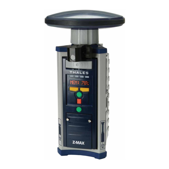
We did, and then we built it! Thales Navigation is proud to introduce the Z-Max Surveying System (Figure 1.1). Because we're surveyors too, we understand how frustrating it is to get out to a job site only to find that a failed, missing, or incorrect part of the system causes down- time. -
Page 25: Figure 1.1 Z-Max Surveying System
Battery issues won't slow you down either. The Z-Max Power Module containing Lithium Ion battery cells can power the receiver for over 13 hours. The Z-Max also includes the latest in wireless technology to eliminate cables when transferring data between devices. -
Page 26: Functional Description
SV, and collects almanac data for all SVs in the constellation. The Z-Max will begin recording satellites automatically as soon as 3 satellites are tracked and will be computing a position when 4 satellites are tracked. -
Page 27: Receiver Memory
A receiver with a 64 MB SD card recording data at 20 second intervals with an average of 8 satellites tracked could log about 28 days worth of continuous data. Standard Z-Max SD memory cards have a capacity of 64Mb. For intensive data storage requirements, higher capacities are available. -
Page 28: Receiver Options
(all options have plug-in internal connectors for power and serial connection to GPS Receiver Module) Vortex UHF Antenna Module • Antenna for Thales U-Link Radio or PDL Radio Power Module • Lithium Ion 'smart' battery module • Max-Run = 13+ hours of operation •... - Page 29 NMEA-format TTT message. OPTION M - GSM Modem The GSM Modem option allows you to set the GSM modem’s data link parameters, dial, and display transmit/receive status of the GSM communication link. Z-Max Surveying System Operation and Applications Manual...
-
Page 30: Table 1.3. Option 3 Observables
OPTION F - Fast Data Output When this option is enabled, the receiver can be set to output NMEA messages and raw data from the serial port at rates up to 10 Hz (0.1 second intervals). Without this option, frequencies up to 5 Hz (0.2 second intervals) are available. OPTION T - Point Positioning When this option is enabled, the receiver can be put into point positioning mode using the $PASHS,PPO command. - Page 31 RTK positions at rate of up to 5 Hz (5 positions per second). 5 Hz Synchronized RTK allows the user to attain the better accuracy of matched time-tagged RTK with nearly the same productivity of Fast CPD. This feature is not available when using RTCM format data. Z-Max Surveying System Operation and Applications Manual...
-
Page 32: Chapter 2 Equipment Description
GPS Receiver Module The Z-Max GPS Receiver Module is the main receiver module (Figure 2.1). The GPS Receiver Module contains the GPS receiver, the memory card, front panel display, external serial ports, USB port, and power port. The GPS Receiver Module also contains the internal Bluetooth module that allows the receiver to wirelessly communicate with external devices. -
Page 33: Figure 2.1 Gps Receiver Module
Figure 2.1 GPS Receiver Module Z-Max Surveying System Operation and Applications Manual... -
Page 34: Front Panel
Front Panel The Z-Max GPS Receiver Module front panel, Figure 2.2, allows you to power on/off the receiver, monitor basic receiver functions, control many receiver parameters, configure surveying parameters and collect survey data. Figure 2.2 Z-Max Front Panel At the top of the front panel are the four tri-colored status LEDs. The LEDs from left to right are the RTK SOLUTION, COMMUNICATION, Data Log, and the Satellite/Power. -
Page 35: Figure 2.3 Led Indicator Lights
Status LEDs The Z-Max GPS Receiver Module front panel has four status LEDs located at the top of the front panel (Figure 2.3). The 3-color LEDs allow you to quickly monitor several receiver functions at a glance. From left to right, the four LEDs are RTK SOLUTION, COMMUNICATION, DATA LOG, and SV/Power. -
Page 36: Figure 2.4 Front Panel Display And Control Keys
Data Log LED The Data Log LED will blink green each time GPS measurement data is recorded to memory. The LED will blink at the frequency of the Recording Interval setting (20 seconds by default). If the SD card fills up and is unable to log any more data to memory, the LED will go to constant red. - Page 37 If the user releases the power key at any time prior to starting the initialization, the receiver will simply power up normally with no reset. Z-Max Surveying System Operation and Applications Manual...
-
Page 38: Figure 2.5 Sd Memory Card Slot And Usb Port
The USB port is a type-B connector. With the USB connection, the Z-Max can establish a bi-directional link to a host computer for transferring data from the SD memory card, or data being streamed in real-time from the Z-Max. -
Page 39: Figure 2.6 Sd Memory Card
SD Memory Card All data recording in the Z-Max is done on an SD (Secure Digital) memory card (Figure 2.6). The SD memory card is a highly-sophisticated memory device about the size of a postage stamp. The SD card slot is located inside the small panel door on the front panel of the receiver (Figure 2.5). -
Page 40: Rear Panel
Figure 2.7 Z-Max Rear Panel Serial Ports The serial ports are used for connecting the Z-Max GPS Receiver Module by cable to external equipment including a PC or handheld computers, external radios, timing devices, and event logging devices. These ports can be used to transfer data or NMEA messages to another device, send receiver commands or queries, receive or transmit RTK or code phase corrections. -
Page 41: Gps Antenna Module
The GPS Antenna Module is designed to either connect directly to the GPS Receiver Module, or to the top of the UHF Antenna Module if the Z-Max is intended for real- time operation. The GPS Antenna Module connects without cables. The base of the... -
Page 42: Power Module
Power Module are rechargeable lithium ion battery cells. The Max-Run Power Module has a capacity of 8.8 amp-hours and should power the Z-Max for over 13 hours in typical user scenarios . The Max-Lite Power Module is a lighter configuration that provides 4.4 amp-hours of power. -
Page 43: Charging
If you require additional or backup battery power, an external power source can be used. An external DC power source connects to the Z-Max external power port via a dedicated power cable. Voltage must be between 10-28 VDC. The external power source can be connected at any time without concern for damage to the Power Module. -
Page 44: Conditioning
charger. The Power Module’s lithium-ion batteries do not have a memory effect, meaning that they can be recharged without being fully discharged with no effect on the battery capacity. In other words, recharge the Power Module whenever it’s convenient. To extend the life span of the batteries in the Power Module, it is best not to always fully discharge them. - Page 45 The key is consistent and steady discharge over a short period of time (1-3 days). This method requires a little more attention, but allows you to use the receiver as you are simultaneously conditioning it. Z-Max Surveying System Operation and Applications Manual...
-
Page 46: Disposition
If the Power Module fails to hold an adequate charge, either due to damage or because it has outlived its useful life, the Power Module can be returned to Thales Navigation for refurbishing. Refer to the hardware limited warranty information for specifics regarding warranty repairs. - Page 47 (or link rate). Configuring the radios is most commonly accomplished using field application software running on the handheld computer. Communication Modules can also be configured using the front panel display of the Z-Max. Instructions for configuring Communications modules using field application software can be found in the software user manuals.
-
Page 48: Figure 2.13 Connecting Communication Module To Gps Receiver Module
The GSM Communications Module supports the use of a SIM card and the Z-Max supports the use of a PIN number. The GSM Communication Module has 2 additional hardware features: a built-in GSM antenna, and a slot to hold the SIM card (Figure 2.14). -
Page 49: Uhf Antenna Module
Figure 2.14 GSM Antenna and SIM Card Slot UHF Antenna Module The Vortex UHF Antenna Module (Figure 2.15) is the UHF antenna for all UHF Communication Modules. The UHF Antenna Module is connected between the GPS Z-Max Surveying System Operation and Applications Manual... -
Page 50: Figure 2.15 Vortex Uhf Antenna Module
Antenna Module and the GPS Receiver Module and routes the radio signal to the radio inside the Communication Module. Figure 2.15 Vortex UHF Antenna Module The UHF Antenna Module connects without cables.The base of the Antenna Module is circular except for a flattened area. Insert the Antenna Module into the antenna receptacle at the top of the GPS Receiver Module. -
Page 51: Handheld Computer/Field Application Software
10 meters away without cables, or may choose to use a cable. FAST Terminal The standard handheld computer used by the Z-Max Survey system is the FAST Terminal (Figure 2.16). Figure 2.16 FAST Portable Data Terminal... - Page 52 Running on the handheld is the field application software, Fast Survey™. Fast Survey has been designed by Thales Navigation specifically for use with the Z-Max Surveying System and emphasizes ease of use and flexibility. For more information on using the FAST Terminal and the Fast Survey software for GPS surveying, refer to the Fast Survey user’s manual.
- Page 53 Z-Max Surveying System Operation and Applications Manual...
-
Page 54: Chapter 3 Getting Started
The purpose of this chapter is to help you become comfortable with the different modules that comprise the Z-Max System and how to operate them. Therefore, this chapter will focus on the basic system setup and will not cover surveying applications. -
Page 55: Figure 3.1. Charging The Power Module
To attach the module, insert the small ledge of the Power Module into the rear of the housing first as shown in Figure 3.2. This will correctly align the module. Using the ledge like a hinge, swing the module Z-Max Surveying System Operation and Applications Manual... -
Page 56: Figure 3.2 Connecting Power Module To Gps Receiver Module
V- Module. While operating the Z- Max in a basic configuration does not require the Communication Module, the module is needed to maintain a weather-tight seal of the Z-Max GPS Module. As you are facing the front panel of the GPS Receiver Module, the Communication Module attaches to the left-hand side. -
Page 57: Figure 3.3 Connecting Communication Module To Gps Receiver Module
The GPS Antenna Module is designed to either connect directly to the GPS Receiver Module, or to the top of the UHF Antenna Module. In order to verify that the Z-Max tracks satellites and records data we will connect the GPS Antenna Module directly to the GPS Receiver Module. Attaching the GPS... -
Page 58: Figure 3.4 Connecting Gps Antenna Module To Gps Receiver Module
Figure 3.4 Connecting GPS Antenna Module to GPS Receiver Module Step 5: Insert the SD Memory Card All data recording in the receiver is done on a removable SD Memory Card that is installed in the GPS Receiver Module. The SD Memory Card slot is located inside the small compartment found on the front panel. -
Page 59: Figure 3.5 Sd Memory Card Installation
During the 2-second period, the LEDs will be solid (not blinking) green. Once the Power button is released, the SV/Power LED should begin to blink red once per second to indicate that the receiver is powered up. Z-Max Surveying System Operation and Applications Manual... - Page 60 CAUTION It is important to power off the receiver using the Power key on the Front Panel before removing the SD card. Step 7: Initialize the Receiver It is a good practice to initialize the receiver prior to operating it for the first time.
- Page 61 GREEN several times between each RED blink. It will blink once for each satellite that is being tracked. With the knowledge of how many satellites are visible, verify that all available satellites are being tracked. The number Z-Max Surveying System Operation and Applications Manual...
- Page 62 of satellites visible can be determined with the Mission Planning module of the GNSS Studio software. Data Recording To verify that data is being recorded to the SD Memory Card: 1. Check the Data Log LED. 2. Within 5 minutes of the completion of an initialization, the Data Log LED should blink green once every 20 seconds, indicating that data is being recorded to the SD Memory Card at the default rate of once every 20 seconds.
- Page 63 ) until the following scrolls across the screen: LAT:N/S ** ** **.***** LON: E/W *** ** **.***** ALT: ***.*** . 7. This position is the current computed position of the Z-Max in degrees/ minutes/seconds of latitude and longitude, and the height above the ellipsoid in meters.
- Page 64 along with many others. A list of the most common parameters may be seen in Appendix B. Ordinarily, receiver parameters that have been changed will return to their default status after a power cycle. However, the front panel display has a function that allows you to save changed receiver settings so that they will remain at their new values even after a power cycle.
- Page 65 Earth is impressive.Tracking satellites and recording measurements is the first step in the process of learning about GPS and the first step in learning how the Z-Max system can be used to dramatically improve the efficiency and profitability of surveying work.
-
Page 66: Chapter 4 Operation
4 control keys (Figure 4.1). The functions in the menu tree are covered in great detail in the Menus section, page 47. Note that although the Z-Max is powered on, the display may not be active. If no keys are pressed for more than 20 seconds, the front panel user interface will shut down to save power. -
Page 67: Figure 4.1 Control Keys
Figure 4.1 Control Keys When GPS measurements are being collected or when surveys are being performed, data is automatically stored in the Z-Max memory. Therefore, there are no additional steps required to save information collected during a survey. Operational parameters control how the Z-Max operates and collects data. -
Page 68: Control Keys
Control Keys The Front Panel User Interface is accessed using the 4 control keys located on the front panel of the Z-Max GPS Receiver Module: the G (up arrow), the H (down arrow), (enter), and M (cancel). The UP and DOWN arrow key are yellow, the ENTER key is green, and the CANCEL key is red. -
Page 69: Table 4.2 Edit Mode Control Buttons
If you backspace when the cursor is at the first character, the Display will cancel any changes to the field, leave Edit mode, and will display the original value of the parameter. Z-Max Surveying System Operation and Applications Manual... -
Page 70: Menus
Menus All of the functionality of the Front Panel User Interface is organized into a multiple- level menu tree. The menu tree is used to access all the available functionality. Use the control keys described above to move around inside the menu tree and to set and enter parameters. -
Page 71: Figure 4.2 Front Panel User Interface Main Menu Tree
See Fig. 4.3 See Fig. 4.4 DELETE BEEP Symbology: Thin arrow - Enter or Cancel Key SAVE Thick Arrow - Up or Down Key Figure 4.2 Front Panel User Interface Main Menu Tree Z-Max Surveying System Operation and Applications Manual... -
Page 72: Table 4.3. Main Menu Submenus
Table 4.3. Main Menu Submenus Submenu Category Description Page Name SYSINFO System Information Basic information about the receiver and bat- tery/memory status SURVEY:mode Survey parameters and status Site parameter settings and survey status information for static, kinematic, RTK base and rover survey modes. SURVCONF Survey Configuration Select survey type and set general parame-... -
Page 73: System Information (Sysinfo)
This process takes several minutes and the field MEM will display xx%. NOTE: The firmware version number, the receiver serial number and the firmware options are needed when contacting Technical Support. Z-Max Surveying System Operation and Applications Manual... -
Page 74: Survey Parameters And Status (Survey:mode)
Survey Parameters and Status (Survey:mode) The SURVEY: mode menu is used to set site-specific survey parameters, execute surveys and view survey status parameters. This menu tree is mode-dependent, meaning that the parameters displayed in this submenu are dependent on the type or mode of survey selected in the Survey Configuration (SURVCONF) screen. - Page 75 Valid range is from 0.00 - 64.0000 meters. Survey Status (Status) This is the entry point to the submenu that displays the kinematic survey status parameters. To enter this submenu, press the ENTER key and the following parameters are accessible: Z-Max Surveying System Operation and Applications Manual...
- Page 76 Current Position (LAT: N/S ** ** **.***** LON:E/W *** ** **.***** ALT: *****.*** m) This field displays the computed latitude and longitude in degrees, minutes, and seconds, and the computed height above the ellipsoid in meters. PDOP (PDOP: **.*) Displays the PDOP value for the current satellite constellation. Number of Satellites Used (#USED: **) Displays the number of satellites used in the position computation.
- Page 77 GPS is GPS time and is displayed between locking onto a satellite and until receiving UTC time corrections. UTC is UTC time. Z-Max Surveying System Operation and Applications Manual...
-
Page 78: Figure 4.3 Survey: Rtk Rover Menu
SURVEY: RTK ROVER The menu tree for the RTK rover is shown in Figure 4.3. FIRST LEVEL THIRD LEVEL SECOND LEVEL TIME ELAPSED ENTER ENTER SURVEY: SITE ANT HT RTK ROVER HRMS CANCEL START VRMS ANT RAD ENTER CANCEL STOP? MANUAL LOGGING POINT... - Page 79 To enter this level, press the ENTER key. Automatic Logging (AUTO POINT) Entry point to the submenus to set automatic logging parameters and to execute an AUTO POINT RTK survey. In an AUTO POINT survey, the user Z-Max Surveying System Operation and Applications Manual...
- Page 80 sets an initial site name and a 'time to stay;' parameter in the Survey Configuration menu (SURVCONF). The receiver will collect data on each point based on the 'time to stay' parameter and automatically increments the Site ID by 1 at the end of the occupation. To enter this level, press the ENTER key.
- Page 81 SD card is inserted. HRMS (HRMS: *.***m) Displays the horizontal RMS value (in meters) computed during data logging. RMS is an estimate of the 1-sigma position accuracy. This field will display up to 99.999 meters. Z-Max Surveying System Operation and Applications Manual...
- Page 82 VRMS (VRMS: *.***m) Displays the vertical RMS value (in meters) computed during data logging. RMS is an estimate of the 1-sigma position accuracy. This field will display up to 99.999 meters. TRAJECTORY Site ID (SITE: ****) Displays and sets the 4-character Site ID. To log data, press ENTER and input a Site ID.
-
Page 83: Survey Configuration (Survconf)
Displays and sets the selected survey mode. Change the survey type by pressing the ENTER key and use the UP/DOWN control keys to choose the desired survey mode. Press ENTER to select it. The mode selected will determine the parameters displayed. Z-Max Surveying System Operation and Applications Manual... - Page 84 SURVCONF: KINEMATIC Epoch Counter (EPOCH COUNTER: ***) Displays and sets the value of the epoch counter. The epoch counter is the number of epochs that will be recorded at each point every recording interval. When the epoch counter counts down to 0, the Site ID (SITE) is automatically reset to question marks ("????").
- Page 85 The Survey Configuration RTK Rover submenu provides access to the more general RTK parameters such as data port, data type and the RTK positioning algorithm. Parameters selected in this menu will affect what parameters are available in the SURVEY: RTK Rover menu. Z-Max Surveying System Operation and Applications Manual...
-
Page 86: Figure 4.4 Survconf: Rtk Rover Menu
ENTER ENTER SURVCONF TYPE RTK ROVER CANCEL CANCEL AUTO POSITIONING LOGGING RTCM A RAW DATA RTCM B LOG TYPE TIME RTCM D TO STAY DISTANCE INTERVAL RECORDING Symbology: INTERVAL Thin arrow - Enter or Cancel Key Thick Arrow - Up or Down Key RECORDING INTERVAL RECORDING... - Page 87 10 seconds. To change this parameter, press the ENTER key. Distance interval (DISTANCE INTERVAL: *.** m) Visible only if LOG TYPE is set to TRAJECT. This parameter sets the distance interval between point computation during a trajectory survey. Valid Z-Max Surveying System Operation and Applications Manual...
- Page 88 range is 0.0 - 999.9 meters. The default is 0.0 meters. To change this parameter, press the ENTER key. Recording Interval (REC INI: ***.*s) Displays and sets the data recording interval. To change this parameter press the ENTER key and use the control keys to enter the desired value in seconds.
-
Page 89: Session Control (Sessions)
Deletes all of the session files on the memory card. To delete all data files, press the ENTER key. The query "Delete ALL sessions?" will appear on the display. Press ENTER to confirm or CANCEL to cancel. Z-Max Surveying System Operation and Applications Manual... -
Page 90: Receiver Parameters Settings (Settings)
Receiver Parameters Settings (SETTINGS) The SETTINGS menu allows you to configure miscellaneous receiver settings such as baud rate, the beep, and the screen language, and perform receiver operations such as memory reset, restore factory defaults, and save set parameters. To get into SETTINGS from the top level, use the UP/DOWN keys until 'SETTINGS' is displayed, then press the ENTER key. -
Page 91: Communication Options (Com Optn)
Enter each submenu by pressing the ENTER key. COM OPTN: THALES RADIO The Thales Radio menu is shown in Figure 4.5. To access the Thales radio menu from COM OPTN, use the UP/DOWN control keys until THALES RADIO is displayed, and press the ENTER key. -
Page 92: Figure 4.5 Thales Radio Menu
ENTER PORT BAUD RATE LOAD THALES RADIO CANCEL PROGRAM Symbology: Thin arrow - Enter or Cancel Key PWR OFF Thick Arrow - Up or Down Key Figure 4.5 Thales Radio Menu Operation... - Page 93 B. When this parameter is set to port B, the port protocol will be switched to RS-422 (required for Thales radios). Any other port selection will change the port B protocol to RS-232. To select a port, press ENTER to access the submenu, scroll to the desired port setting and press ENTER to select it.
- Page 94 Communication Module. It is required that the port needs to be set to D before entering this field. Press the ENTER key to power off the Thales radio. COM OPTN: PDL RADIO The PDL Radio menu is shown in Figure 4.6.
-
Page 95: Figure 4.6 Pdl Radio Menu
ENTER PORT BAUD RATE LOAD RADIO CANCEL SENSITIVITY LINK SPEED Symbology: Thin arrow - Enter or Cancel Key PROGRAM Thick Arrow - Up or Down Key Figure 4.6 PDL Radio Menu Z-Max Surveying System Operation and Applications Manual... - Page 96 The PDL radio parameters are described in order as follows: Radio serial port setting. (PORT) The PORT submenu sets the serial port to which the radio is connected. Port options are A, B, or D. The default is port D (the internal radio port) and should not be changed if using the Communication Module.
-
Page 97: Figure 4.7 Gsm Rover Menu
The GSM Rover menu is shown in Figure 4.7. ENTER SETUP MODE DIAL BAND HANG UP PHONE ROVER CANCEL STATE RETRY Symbology: Thin arrow - Enter or Cancel Key Thick Arrow - Up or Down Key Figure 4.7 GSM Rover Menu Z-Max Surveying System Operation and Applications Manual... - Page 98 To access the GSM ROVER menu from COM OPTN, press ENTER and use the UP/ DOWN keys until GSM ROVER is displayed. Press the ENTER key to enter the submenu. When the GSM Rover menu is entered, the SETUP submenu is the first submenu displayed.
- Page 99 GSM ON = power on GSM OFF = powered off GSM INITIALIZED = modem has been initialized DIALING = dialing the base modem ONLINE = powered on and connected to the base modem. Z-Max Surveying System Operation and Applications Manual...
-
Page 100: Figure 4.8 Gsm Base Menu
COM OPTN: GSM BASE The GSM Base menu is shown in Figure 4.8. ENTER ENTER BAND SETUP BASE CANCEL CANCEL HANG UP Symbology: Thin arrow - Enter or Cancel Key Thick Arrow - Up or Down Key STATE Figure 4.8 GSM Base Menu To access the GSM BASE menu from COM OPTN, press ENTER and use the UP/ DOWN control keys until GSM BASE is displayed. - Page 101 Displays the current state of the GSM modem. Status values are: GSM ON = power on GSM OFF = powered off GSM INITIALIZED = modem has been initialized ONLINE = powered on and connected to the remote modem. Z-Max Surveying System Operation and Applications Manual...
-
Page 102: Data Recording
The Z-Max can be explicitly set to record in any data mode by entering text commands through the serial port (see Appendix B). -
Page 103: Table 4.4. Data Recording Modes
Almanac file ALMyy.ddd Raw data B-file Ephemeris data E-file Position data C-file Site data S-file Event marker data M-file Almanac data ALMyy.ddd RTK epoch solution records Vec- T file tor solution O file Z-Max Surveying System Operation and Applications Manual... -
Page 104: Downloading The Data
ALMyy.ddd Downloading the Data During survey operations data is stored in either the SD memory card in the Z-Max or in the memory of the handheld computer. Downloading data involves the transfer of this data to the PC for subsequent processing. During the downloading process, the session files are decoded and converted into the individual data files (B-file, E-files, etc) and stored onto the desired directory of the PC. - Page 105 7. A list of any available USB devices is displayed in the drop-down list. Select the correct port/device and press OK. Download will display the session files on the SD card in the left pane. Z-Max Surveying System Operation and Applications Manual...
- Page 106 8. In the right pane of the Download main window, change the destination directory to either the project directory or the directory where you want the data files to be stored. 9. Select the desired session data file(s) from the SD card pane that you want to download and drag them to the PC pane.
-
Page 107: Downloading The Handheld Computer Data
12. The selected files will be downloaded into the selected destination directory. A progress dialog box indicates the status of the download. Note that the files on the data collector will not be erased after download is complete. Z-Max Surveying System Operation and Applications Manual... -
Page 108: Data Files
Data Files During a data recording session, all the data for that session is stored on the SD memory card as a U-file. The U-file is a compressed file that contains the data that is converted to individual files during the download process. These files include: the raw data files (B-files) that store all carrier and code phase data, ephemeris files (E-files) that store satellite position and timing information, and a site information files (S-files) that store site occupation information. -
Page 109: Figure 4.9 File Naming Convention
The next 4 characters indicate the station location or site name. If the user has not entered a site name, then these 4 characters are underscores ("____") unless a previous location name is still in memory. If the site name Z-Max Surveying System Operation and Applications Manual... - Page 110 has been changed during the course of the session, then the last entered site name is used. The next character is the session identifier. This field automatically increments from A-Z with each new session on a given day. The next two characters indicate the last two digits of the year when the session was terminated (e.g.
-
Page 111: Warning Messages
Not Loaded Yet The LOAD function was not per- Load radio parameters (LOAD) sub- formed prior to programming user menu and then resend the user parameters. parameters (PROGRAM) submenu. Z-Max Surveying System Operation and Applications Manual... - Page 112 Table 4.6. Warning Messages (continued) Warning Definition Action GSM WARNINGS MODEM Not Detected GSM modem not detected Verify a GSM modem is in the Radio .Module, and verify that the module is securely connected. MODEM Not Responding Can not communicate with GSM Verify a GSM modem is in the Radio modem .Module, and verify that the module...
- Page 113 SD MEMORY CARD WARNINGS No Data Card Detected The SD memory card is either Insert or re-insert SD memory card. missing or not properly inserted and has not been detected; no data recording will be done. Z-Max Surveying System Operation and Applications Manual...
- Page 114 Table 4.6. Warning Messages (continued) Warning Definition Action Data Card Full There is no space left on the SD Delete data from the current card or memory card. replace current SD memory card with another SD memory card with available memory. †...
- Page 115 Download again to perform this time. proper shutdown routine. † - Indicates warning is permanent. The warning will NOT go away if the condition disappears, but only if it is acknowledged. Z-Max Surveying System Operation and Applications Manual...
-
Page 116: Section 2 - System Guide To Post-Process Surveying
SECTION 2 System Guide Post-process Surveying... - Page 117 Z-Max Surveying System Operation and Applications Manual...
-
Page 118: Chapter 1 Introduction
Introduction Although difficult to believe, it has been over 20 years since precise positioning using the Global Positioning System (GPS) was first demonstrated. In a relatively short time, this capability was put to commercial use with the introduction of the Macrometer V-1000 GPS receiver. -
Page 119: The Global Positioning System (Gps)
Z-Max Surveying System Operation and Applications Manual... -
Page 120: Surveying With Gps
Surveying with GPS A GPS surveying system consists of at least two GPS receivers. The receivers collect data simultaneously to determine the location of one receiver relative to the other(s). The positional relationship between the receivers is presented in the form of a vector, i.e. -
Page 121: Post-Processing Gps Data
Processing is accomplished by the GNSS Studio software included with the system. Processing normally occurs on a PC back at the office, but can also be performed on a laptop in the field. Z-Max Surveying System Operation and Applications Manual... -
Page 122: Applications
To accomplish the post-processing, data is downloaded from each GPS receiver into the computer. The processing software utilizes this data to calculate vectors between all GPS receivers operating simultaneously. The vectors define the 3-dimensional relationship between the GPS receivers. From these vectors, coordinates are determined for all points in the project, based on the coordinates of one or more known points. -
Page 123: Thales Navigation Z-Max System
GPS surveys. The Z-Max System is built around the Thales Z-Max dual- frequency GPS receiver. Being a dual-frequency receiver (utilizes satellite signals on both L1 and L2 frequencies), the Z-Max makes your GPS system more versatile and productive compared to a post-process GPS system based on a single-frequency GPS receiver. -
Page 124: Chapter 2 System Components
System Components The Z-Max GPS surveying system is made up of a number of modules. If setup is taken step by step, the process of assembling a system for collecting GPS data is simple. The trick is understanding the purpose of each module in the system and how they connect to each other. -
Page 125: Gps Antenna Module
GPS receiver antenna must be precisely centered over the point. The height of the GPS antenna above the point must also be measured. The vertical position of the point is determined by subtracting the Z-Max Surveying System Operation and Applications Manual... -
Page 126: Z-Max Power System
Each GPS receiver in the system will have one GPS receiver antenna. The GPS antenna for the Z-Max system is the GPS Antenna Module, Figure 2.2. The GPS Antenna Module contains highly sensitive antenna electronics housed in a durable, waterproof housing. -
Page 127: Communication Module
V-Module, Figure 2.4. Operating the Z-Max during a post-process survey does not require data links. The empty V-Module is needed to maintain a weather-tight seal of the Z-Max Z-Max Surveying System Operation and Applications Manual... -
Page 128: Mounting Accessories
It attaches to the Z-Max System between the bottom of the GPS Receiver Module and the tribrach. The HI Measurement Plate is only used when the Z-Max System is either a static receiver or a kinematic base station. -
Page 129: Figure 2.6 Range Pole Rf Adapter
Range Pole RF Adapter When the Z-Max System is operating as a backpack-mounted kinematic rover, a cable is required to connect the GPS Receiver Module in the backpack to the GPS Antenna Module on the survey pole. The Range Pole RF Adapter is the module where the cable physically connects to the survey pole and the GPS Antenna Module. -
Page 130: Figure 2.7 Max-Rf Adapter
Figure 2.7 Max-RF Adapter Pole Adapter The Pole Adapter is used when the Z-Max System is functioning as a kinematic post-processed rover. The Pole Adapter is used to raise the GPS Antenna Module high enough on the survey pole so that the antenna’s view to the satellites is not blocked by the user. -
Page 131: Handheld Computer
Figure 2.8 Pole Adapter Handheld Computer A handheld computer is an optional component of the Z-Max System. It serves as a graphical interface to the Z-Max GPS receiver. The Z-Max GPS Receiver Module has a Front Panel User Interface for configuring parameters and controlling surveys. For some types of post-processed surveys, a handheld computer with a graphical user interface is desireable. -
Page 132: Figure 2.9 Fast Terminal
wirelessly communicate with the receiver from up to 10 meters away. The FAST Terminal runs the FAST Survey Field Application software discussed below. Figure 2.9 FAST Terminal System Components... -
Page 133: Z-Max Application Software
Field Application Software The field application software resides in the handheld computer/data collector. As with the handheld computer, this is an optional component to the Z-Max System for post- processing. The field application software offers an enhanced interface to the Z-Max receiver, supporting additional status information and operational capabilities not available through the Front Panel User Interface of the receiver. - Page 134 Z-Max surveying system. Using GNSS Studio, you can plan field operations, prepare feature codes or stakeout files prior to the field work, transfer data between the office computer and field devices, process collected data, and create your choice of detail rich maps and reports. This is all accomplished through a user interface which is a rare mix of simplicity and power.
- Page 135 Z-Max Surveying System Operation and Applications Manual...
-
Page 136: Chapter 3 Connecting System Hardware
This requires that the modules be connected correctly. In the following sections, we will examine the connectivity of the Z-Max modules. Below is a list of module connections for a Z-Max post-processed survey system. -
Page 137: Gps Receiver - Receiver Power System
Figure 3.1 Connecting GPS Antenna Module to GPS Receiver Module GPS Receiver - Receiver Power System Supplying power to the Z-Max System can be accomplished by using the Power Module or by connecting a DC power source (10-28V) to the external power port. -
Page 138: Figure 3.2 Connecting Power Module To Gps Receiver Module
Power Module clicks into place. Figure 3.2 Connecting Power Module to GPS Receiver Module If the Z-Max System is to collect data unattended for a period of time exceeding the capability of the Power Module, an external power source can be used. External DC sources can be plugged in using a cable and the external power port. -
Page 139: Handheld Computer - Gps Receiver
When both the Power Module and external power source are used, the Z-Max will draw power from the external source first. If the voltage supplied to the external port is insufficient to power the receiver, the Z-Max will automatically switch over to the Power Module with no interruption in operation. -
Page 140: Figure 3.4 Fast Terminal
If you need to use a cable, the computer communication cable connects to the Z-Max via one of the two serial ports on the back panel of the receiver. These two ports are labeled SERIAL A and SERIAL B. -
Page 141: Z-Max System - Tripod/Survey Pole/Backpack
Since the GPS Antenna must be centered and leveled over the survey point to be able to achieve centimeter-level accuracy, it is important to understand how to connect the Z-Max to the survey mounting device. We will review the three basic types of setups and the equipment configuration for each. -
Page 142: Figure 3.5 Static Setup
Figure 3.5 Static Setup Rover - A rover setup is designed to be mobile and carried by a person. The Z- Max rover setup is used for post-processed kinematic data collection. A Z-Max rover may either be range-pole mounted or backpack mounted. -
Page 143: Figure 3.6 Pole-Mounted Rover Setup
1. Attach the GPS Antenna Module to the Pole Adapter. 2. Attach the GPS antenna and Pole Adapter assembly to the GPS Receiver Module. Z-Max Surveying System Operation and Applications Manual... -
Page 144: Figure 3.7 Z-Max Backpack Connectivity
3. Mount the Z-Max assembly in the backpack with the GPS Antenna Module pointing up. 4. Attach the handheld computer (if applicable) to SERIAL A on the GPS Receiver Module using the data collector cable. Figure 3.7 Z-Max Backpack Connectivity Before connecting the cables from the backpack to the pole assembly, put on the backpack. -
Page 145: Figure 3.8 Backpack-Mounted Rover Setup
Figure 3.8 Backpack-Mounted Rover Setup Congratulations! You have learned about the Z-Max modules, how they work and how they fit together to create a flexible, streamlined system for recording GPS data. In the following chapters you will learn about how to set up the equipment in the field and execute a post-processed GPS survey. -
Page 146: Chapter 4 Survey Preparation And Execution
The soft case (Figure 4.1 and Figure 4.2) not only contains the Z-Max system and all its various modules but has compartments for optional items for post-processing systems such as the handheld computer, cables, the Range Pole RF Adapter, the Pole Extender, and the HI measurement device. -
Page 147: Figure 4.1 Soft Case
Figure 4.1 Soft Case Figure 4.2 Inside View of Soft Case Z-Max Surveying System Operation and Applications Manual... -
Page 148: Static Surveys
With the previous checklist completed, field data collection can begin. When collecting data using the Static method, each Z-Max receiver will follow precisely the same steps in equipment setup and survey execution. These steps are presented below. - Page 149 GPS tripod (Figure 4.3). Either is sufficient for the task but the fixed height tripod is recommended since it eliminates the possibility of incorrectly determining the instrument height of the antenna. Z-Max Surveying System Operation and Applications Manual...
-
Page 150: Figure 4.3 Conventional And Fixed-Height Tripods
Insert the brass tribrach adapter through the hole in the HI Measurement Plate and screw the adapter/plate into the 5/8” threaded receptacle in the bottom of the Z-Max GPS Receiver Module. 5. Mount the GPS Receiver Module on the tripod... -
Page 151: Figure 4.4 Measuring Hi (Height Of Instrument) Of Gps Antenna
GPS receiver (Figure 4.4). Use the tape measure to measure from the center of the point to the measurement point of the Z-Max. The height from the bottom of the GPS Receiver Module to the GPS Antenna Module is printed on the outside of the Receiver Module housing. - Page 152 Both the Site ID and HI are required for each observation during data processing. These parameters can be entered either in the SURVEY:Static menu of the Z-Max front panel user interface or by using the handheld computer running field application software. The Site ID and the antenna HI should also be written down on the observation log.
- Page 153 A general guide for good conditions is five or more satellites tracked continuously during the occupation and PDOP less than 4. For dual-frequency receivers, a reasonable occupation time for the Z-Max system is 10 minutes plus 1 minute for every kilometer of vector length. For example, if three...
-
Page 154: Figure 4.5 Z-Max Survey System Performing A Static Survey
Once data collection is completed at a given location, the Z-Max receiver system can be moved to the next location for another data collection session. Remember that only common data between receivers is used. When the receiver is powered down the active measurement file is automatically closed, and when the receiver is powered back up a new measurement file is automatically created. -
Page 155: Kinematic Surveys
This requires that the rover system be set up in a portable configuration; either on a survey pole, or as part of a backpack. These two configurations are described below. Z-Max Surveying System Operation and Applications Manual... - Page 156 1. Connect system components Connect all the modules in the system as listed below. The pole-mounted configuration will have different connections than the backpack mounted configuration. Refer to the previous chapter on how to establish these connections. Check these connections to ensure the modules are secure and seated properly.
-
Page 157: Figure 4.6 Pole-Mounted Rover System
On a pole-mounted system, the HI is based on the known fixed length of the survey pole plus the height of Z-Max assembly. On a backpack mounted system, the HI is the known fixed length of the survey pole plus the height of the Range Pole RF Adapter, the Pole Extension and the GPS Antenna Module. -
Page 158: Figure 4.7 Backpack-Mounted Rover System With Survey Pole
Figure 4.7 Backpack-mounted Rover System with Survey Pole 4. Mount handheld computer For kinematic method of data collection, an optional handheld computer and application software add utility to the system. The handheld computer is mounted onto the survey pole, as shown in Figure 4.8. A special mounting bracket for the handheld is typically required when a handheld computer is used. -
Page 159: Figure 4.8 Fast Terminal Handheld Computer Mounted On Rover Pole
NOTE: It is very important that the recording interval on the rover is set to the same interval as the base. In addition, there are parameters that, while not required, can be very useful in executing a kinematic survey. Z-Max Surveying System Operation and Applications Manual... - Page 160 The Epoch Counter counts the time that each point is occupied in the kinematic survey. When the Site ID is entered, the epoch counter will automatically decrement with each epoch of GPS measurements recorded. When the counter gets to 0, an audible alarm is generated to indiate that data collection at that point is complete, and the Site ID is automatically set to question marks.
-
Page 161: Kinematic Survey Execution
This process involves two primary functions. These functions are Initialization and Point Observation. Each of these functions is discussed below. Z-Max Surveying System Operation and Applications Manual... - Page 162 Kinematic Initialization Prior to performing any feature location with the rover system, the receiver must first go through an initialization process. The initialization process is required to produce highly precise positions. Prior to initialization, the rover system will compute positions at a degraded level of accuracy.
- Page 163 1. Initialize on-the-fly When using a dual-frequency GPS system such as the Z-Max, there is no requirement that initializations be performed while standing still at one location. It is possible to initialize your kinematic survey while moving about the project site (thus the term on-the-fly).
- Page 164 You successfully continue to collect topo points for approximately 30 minutes without loss-of-lock. You now are in the perimeter areas were there are trees close to the edge of the landfill. While attempting to locate topo points right on the edge of the trees, the kinematic alarm in the receiver sounds indicating that you have lost your initialization.
- Page 165 You successfully position 10 points when you suddenly lose lock on satellites due to an obstruction (the Z-Max receiver will sound an alarm when fewer than 5 satellites are locked). You must now re-initialize your survey.
- Page 166 Continuous Kinematic The Continuous Kinematic mode of data collection is best used when positioning linear features such as roads. The idea is to trace the feature to be positioned or mapped. As you walk along this feature, positions are being determined at a specified interval, delineating the feature.
- Page 167 Congratulations! You have finished the section on data collection for Static and Kinematic GPS Surveying. Now you should have a basic understanding about how to setup a Z-Max System and collect GPS measurements in a number of different modes. Collecting GPS measurements is the first step to realizing the productivity that Z-Max surveying technology can offer.
-
Page 168: Chapter 5 Troubleshooting
Troubleshooting If you followed all the steps to prepare the Z-Max System to perform a survey and the system is not working, this section will provide a resource to help determine the cause of the problem. Problems usually fall into one of two categories, something was forgotten or a component was not installed properly. -
Page 169: Gps Receiver Does Not Track Satellites
Receiver not powered up 1. Turn on the receiver. Press and hold the power switch on the Z-Max front panel. The button must be held for two seconds since there is a delay in power on. You will see the power LED turn on and the display will begin to show text. - Page 170 Go to step C if the problem is not yet resolved. c.You may have a malfunctioning GPS receiver. Call your local dealer or Thales Navigation Technical Support for assistance. Receiver is powered up Go to step 3 below. Step 3. Is the GPS Antenna Module Connected to the Receiver? The GPS Antenna Module must be securely connected to the GPS Receiver Module for the receiver to track satellites.
-
Page 171: Gps Receiver Is Not Recording Data
Step 2. Is the SD memory card installed in the GPS Receiver Module? The Z-Max GPS receiver logs data to a removable SD data card. The data card must be installed in the Z-Max GPS Receiver Module for the receiver to log data. Check to ensure that the data card is properly installed. - Page 172 Step 3. Is the data card full? The Data log LED on the front panel of the Z-Max GPS Receiver Module will be solid red if the data card in the receiver is full. Check the LED to determine if the card is full.
- Page 173 Z-Max Surveying System Operation and Applications Manual...
-
Page 174: Section 3 - System Guide To Rtk Surveying
SECTION 3 System Guide RTK Surveying... - Page 175 Z-Max Surveying System Operation and Application Manual...
-
Page 176: Chapter 1 Introduction
Introduction In the early days of surveying with GPS, data collection time on a single point was measured in hours, few was the number of points established in a day, and completion of a large project could take weeks. The results of a day's work were not known until much later when the data was finally processed at the main office. -
Page 177: The Global Positioning System (Gps)
The more sophisticated receivers are capable of receiving raw data from a second GPS receiver collecting data simultaneously and combining this data with its own to compute a very accurate position of its location in real-time. This is how an RTK receiver functions. Z-Max Surveying System Operation and Applications Manual... -
Page 178: Real-Time Kinematic Surveying
Real-Time Kinematic Surveying RTK mode of GPS surveying requires that at least two GPS receiver systems are functioning simultaneously, as shown in Figure 1.1. In fact, this is true for any mode of GPS use where better than a few meters (SA disabled) of positional accuracy is required. -
Page 179: Applications
Given the coordinates of a point from another source such as an aerial photograph or a to-reach description, you are able to find the exact location on the ground that corresponds to those coordinates. Conventionally, this is Z-Max Surveying System Operation and Applications Manual... -
Page 180: Limitations
This does not mean that GPS RTK is only useful in areas with a wide-open view of the sky. Advanced RTK systems like the Z-Max can be used very effectively and accurately in partially obstructed areas. The critical factor is to be able to observe, at any given time, enough satellite signal to accurately and reliably compute a position. -
Page 181: Thales Navigation Z-Max
PC. With the Z-Max System, RTK surveying is more cost-effective than it's ever been. -
Page 182: Chapter 2 System Components
System Components In this chapter we will provide an overview of the components that make up the Z-Max RTK System for Surveying. The Z-Max RTK Surveying System is made up of a number of modules. If setup is taken step by step, the process of assembling a system for collecting GPS data is simple. -
Page 183: Gps Receiver And Antenna
RTK system and connect them to the specific modules of the Z-Max System. GPS Receiver and Antenna In the Z-Max System, the GPS receiver is part of the GPS Receiver Module. The GPS antenna is in the GPS Antenna Module. -
Page 184: Figure 2.1 Z-Max Gps Receiver Module
Figure 2.1 Z-Max GPS Receiver Module The GPS receiver processes and stores the satellite signals. An RTK system requires at least two GPS receivers; a base receiver and a rover receiver. The base receiver is usually mounted on a tripod over the known point. The rover receiver is either mounted on a pole (Figure 2.2) or mounted on a backpack... -
Page 185: Figure 2.2 Pole Mounted Z-Max Rtk Receiver
Figure 2.2 Pole Mounted Z-Max RTK Receiver Figure 2.3 Backpack Z-Max RTK Receiver Z-Max Surveying System Operation and Applications Manual... -
Page 186: Figure 2.4 Gps Antenna Module
The Z-Max GPS Receiver Module is a 12-channel, dual-frequency receiver. The receiver has a removable SD memory card for internal data storage and is designed to run on about 4 watts of power to maximize the amount of uninterrupted time that the receiver can be operated in the field. The receiver is capable of functioning as the base or the rover receiver in both RTK and post- processed surveys. -
Page 187: Data Link
Typical data links for mobile RTK systems are, UHF radio, VHF radio and cellular modem. Various different types of data links are available with the Z-Max RTK System. Distance requirements, regional regulatory statutes, local interference and available infrastructure will influence which data link to use. - Page 188 UHF Radios The Z-Max uses data links that operate in the UHF frequency range. UHF radios can communicate over long distances. Actual radio range depends on factors including the transmitter power, the height of the transmitting antenna, the topology over the transmission path and rover sensitivity. Although UHF radios...
-
Page 189: Figure 2.6 Thales U-Link Radio
Figure 2.6 Thales U-Link Radio NOTE: When using the Thales U-Link base radio, the radio must be connect to Serial B. Pacific Crest PDL Radio The Pacific Crest PDL radio, Figure 2.7, is a popular data link option because of its reliable performance and range of functional options. The PDL rover is housed in the Z-Max Communication Module. - Page 190 Cellular Modems Cellular communications is a relatively new option for RTK surveying. It is a system that operates using commercial cellular infrastructure and is independent of distance. Cellular communications are rarely affected by any kind of interference or movement and are robust for RTK systems. Cellular data links for RTK do have some disadvantages.
-
Page 191: Figure 2.8 Gsm Communication Module
The GSM modems used in the Z-Max RTK system are housed in the Communication Module, Figure 2.8. Dialing of the modem can be controlled by the Front Panel User Interface of the Z-Max or through application software running on a handheld computer. - Page 192 Therefore, the Z-Max RTK System will generally use one of the following data link configurations: • A Cellular modem at both the base and the rover. The cellular modem and antenna are inside the Communication Module for both the base and the rover receiver.
-
Page 193: Power Sources
The base system can use one of many possible power sources as the power supply including a Z-Max Power Module or an external DC power source such as a battery, an AC/DC converter, or an auto cigarette lighter. -
Page 194: Figure 2.10 Power Module
In the rover RTK system, weight and runtime are competing requirements. Since the rover is carried by the user, a heavy battery is undesirable. The Z-Max System offers the flexibility of a run-time optimized (13+ hours) and a weight optimized (6+hours) option. -
Page 195: Mounting Accessories
It attaches to the system between the bottom of the GPS Receiver Module and the tribrach. The HI Measurement Plate is only used when the Z-Max system is a base station receiver. The HI Measurement Plate is not necessary when using a fixed-height tripod. -
Page 196: Figure 2.12 Pole Adapter - Pole-Mounted System
Pole Adapter Figure 2.12 Pole Adapter - Pole-Mounted System Range Pole RF Adapter - When the Z-Max system is operating as a backpack- mounted RTK rover, a cable is required to connect the GPS Receiver Module in the backpack to the GPS Antenna Module on the survey pole. The Range Pole RF Adapter (Figure 2.13) is the module where the cable physically connects to... -
Page 197: Figure 2.13 Range Pole Rf Adapter - Backpack Mounted System
RF Adapter Figure 2.13 Range Pole RF Adapter - Backpack Mounted System Max-RF Adapter - When the Z-Max system is operating as a backpack-mounted RTK rover, a cable is required to connect the GPS Receiver Module in the backpack to the GPS Antenna Module on the survey pole. The Max-RF Adapter is the module where the cable physically connects to the GPS Receiver Module. -
Page 198: Handheld Computer/Field Application Software
Figure 2.14 Max-RF Adapter Handheld Computer/Field Application Software The user must interface with the receiver in order to configure and run an RTK survey. The device that is typically used to interface with the receiver is a handheld computer running field application software. While it is possible to configure and perform RTK surveys using the Front Panel User Interface, a handheld computer is more convenient and provides more capabilities. -
Page 199: Figure 2.15 Fast Terminal
FAST Terminal The standard handheld computer used by the Z-Max Survey system is the FAST Terminal (Figure 2.15). The FAST Terminal is a lightweight, rugged handheld computer developed especially for surveying applications. It is designed to withstand conditions encountered during a variety of field scenarios. The FAST Terminal uses Bluetooth wireless technology so that no cables are required between the handheld and the receiver. -
Page 200: Office Software
This concludes the description of individual hardware and software modules which make up the Z-Max System for RTK surveys. Next, we will examine how the individual Z-Max hardware and software modules fit together to build a powerful system for real- time navigation and data collection. - Page 201 Z-Max Surveying System Operation and Applications Manual...
-
Page 202: Chapter 3 Hardware Connectivity
Each of these configurations will be discussed separately. Lastly, remember that the Z-Max RTK system comes with a choice of data links and the data link used will have a big effect on the system configuration. Each type of data link will also be discussed separately where appropriate. -
Page 203: Figure 3.1 Gps Receiver - Power Module Connection
Module clicks into place. Figure 3.1 GPS Receiver - Power Module Connection If the Z-Max system is to collect data unattended for a period of time exceeding the capability of the Power Module, an external power source can be used. External power is applied to the Z-Max GPS Receiver Module by connecting the power source with a cable (Figure 3.2) to the external power port located on the rear panel of the... -
Page 204: Gps Receiver - Gps Antenna
In case both the Power Module and external power source are used, the Z-Max will draw power from the external source until the voltage drops or power is interrupted. If the power from the exteral power source is insufficient, the Z- Max will automatically switch over to the Power Module with no interruption in operation. -
Page 205: Gps Receiver - Communication Module
If the RTK base system is using UHF radios, then an empty Communication Module housing (called V-Module) is required to protect the Z-Max. If the RTK base system is using a cellular modem, then the Communication Module serves as the modem transmitter. -
Page 206: Gps Receiver - Tripod
SIM card. GPS Receiver - Tripod The Z-Max RTK base system is designed to attach directly to a tripod. Center and level the tripod over the ground mark prior to attaching the receiver. On the bottom of the GPS Receiver Module is a standard 5/8"... -
Page 207: Figure 3.5 Gps Receiver Module And Tripod Adapter
When fixed height tripods are being used, the vertical height of the tripod is known. It is not necessary to measure the HI as it can be computed. To determine the total vertical height (HI) of the setup, add the vertical height of the Z-Max system to the known height of the tripod. -
Page 208: Figure 3.6 Gps Receiver Module Fixed Height Tripod Installation
Carefully set the assembly (Z-Max, mounting plate, tribrach adapter) onto the tripod. Once the Z-Max is securely mounted to the tripod, the height of the GPS antenna must be measured. The HI measurement plate is used to measure a slant height from the receiver to the survey mark. -
Page 209: Radio - Radio Antenna
Thales U-Link Transmitter The transmitting antenna connects directly to the Thales U-Link radio without a cable. The advantage of a direct antenna connection is that there is little signal power loss between the transmitter and the antenna. -
Page 210: Figure 3.8 Thales U-Link Radio Antenna
Figure 3.9. The radio and the antenna together are raised as high as possible to maximize transmission distance. Figure 3.8 Thales U-Link Radio Antenna Hardware Connectivity... -
Page 211: Figure 3.9 Mounting The Thales U-Link Transmitter
Screw the antenna on to the top of the telescoping pole or tripod and connect the antenna cable to the radio antenna port. Z-Max Surveying System Operation and Applications Manual... -
Page 212: Gps Receiver - Radio
The radio is generally attached to the tripod. On the radio is a built-in tripod mounting bracket. Locate the mounting flange at the top portion of one of the tripod legs and hook the radio in place as shown in Figure 3.10. Figure 3.10 PDL Radio and Radio Antenna CAUTION It is important that the radio antenna be connected to the radio prior to applying... - Page 213 The RTK base configuration using a Pacific Crest 35 Watt base transmitter requires a Y-cable. The receiver end of the PDL radio data/power cable can connect to either serial port A or serial port B of the Z-Max but port B is recommended.
-
Page 214: Figure 3.11 Connecting Pdl 35-W Radio & Z-Max Gps Receiver Module
Y-cable. The receiver end of the PDL radio data/power cable can connect to either serial port A or serial port B of the Z-Max but port B is recommended. At the radio end of the PDL data/power cable is a 5-pin right angle Lemo connector. -
Page 215: Figure 3.12 Connecting Pdl 2-W Lpb Radio & Z-Max Gps Receiver Module
B of the Z-Max. When the U-Link radio is used, the Z-Max serial port B must be configured in RS-422. This is done in the radio configuration/port setup menu of the Front Panel User Interface. -
Page 216: Figure 3.13 Connecting Thales U-Link Radio & Z-Max Gps Receiver Module
Figure 3.13 Connecting Thales U-Link Radio & Z-Max GPS Receiver Module It is recommended that the radio be connected to the receiver and the external battery be connected to the Z-Max external power port prior to powering up the receiver. This will ensure a clean power-up of the radio. -
Page 217: Handheld Computer - Gps Receiver
A Bluetooth enabled handheld can wirelessly communicate with the receiver up to 10 meters away. The Z-Max can also use a serial cable to communicate with other devices such as handheld computers and a PC. Running on the FAST Terminal is specialized software for field surveying called, FAST Survey. -
Page 218: Figure 3.14 Z-Max Rtk Base With Cellular Modem
Module. When using the Thales U-Link radio, power is supplied from the Z- Max serial port. In this configuration, an external power source is required for the Z-Max. Plug the external power source into the external power port of the Z-Max GPS Receiver Module. -
Page 219: Figure 3.15 Thales U-Link Radio In Rtk Base Configuration
The Connection to the Z-Max: 1. External power cable plugged into the port labeled "POWER". This cable connects an external power source to the Z-Max GPS Receiver Module. This is an essential connection to power the radio 2. Radio data/power cable plugged into the port labeled "SERIAL B". This cable connects the Z-Max GPS Receiver Module to the radio. -
Page 220: Figure 3.16 Rtk Base With Thales U-Link Radio
The PDL connections are: 1. The radio data/power cable plugged into the radio's DATA/PWR port. This cable connects the radio to the Z-Max GPS Receiver Module and also connects the radio to an external power source. 2. The radio antenna cable plugged into the ANTENNA port that connects the radio to the radio antenna. -
Page 221: Rtk Rover System
The Connection to the Z-Max: 1. External power cable plugged into the port labeled "POWER". This cable connects an external power source to the Z-Max GPS Receiver Module. This is an optional connection and is only required if the power requirements will exceed the capacity of the Power Module. -
Page 222: Pole-Mounted Rover System
A common type of wireless modem used for GPS RTK is UHF radio. When using UHF radio, a UHF antenna is needed. The Z-Max rover system uses the UHF Antenna Module for receiving UHF signal. Some types of wireless modems, like cellular, use antennas that are attached directly to the Communication Module. -
Page 223: Gps Receiver - Gps Antenna
Module so that the flattened side of the Antenna Module base is lined up with the flattened area inside the top of the receiving module and insert the GPS Antenna Module into the antenna receptacle. If the modules are correctly aligned, the GPS Z-Max Surveying System Operation and Applications Manual... -
Page 224: Gps Receiver - Communication Module
The GPS antenna can be connected to the receiver at any time before or after the receiver is powered on. The attachments of the modules provide the water seal for the Z-Max so make sure that the connection is secure. GPS Receiver - Communication Module Just like the RTK base system, the Communication Module connects to the right-hand side of the GPS Receiver Module. -
Page 225: Gps Receiver - Receiver Power System
GPS Receiver Module. To connect the module, align the module and the housing and insert the small ledge of the module into the rear of the GPS Receiver Module housing as shown in Figure 3.22. Swing the module closed until the Z-Max Surveying System Operation and Applications Manual... -
Page 226: Handheld Computer - Gps Receiver
Bluetooth module is present in handheld terminal. If you need to use a cable, the computer communication cable connects to the Z-Max via one of the two serial ports on the back panel of the receiver. These two ports are located on the rear panel of the receiver and are labeled SERIAL A and SERIAL B. -
Page 227: Mounting The System To The Pole
Figure 3.23 FAST Terminal Handheld Computer FAST Terminal The FAST Terminal is offered as an option with the Z-Max system for RTK surveys. It is lightweight, durable and weather resistant for use in outdoor environments. The FAST Terminal allows both wireless and cabled connections from the Z-Max Receiver Module to the PC. -
Page 228: Fully Connected Z-Max Rover System
Fully Connected Z-Max Rover System The typical pole-mounted Z-Max Rover System will not have any cable connections. All the modules will be connected directly to the GPS Receiver Module. Even the handheld computer is wireless and may be mounted on the pole with a special mounting bracket.The fully connected pole-mounted system is shown in Figure 3.24. -
Page 229: Gps Receiver - Communication Module
GPS Receiver - Receiver Power System Under most operational conditions, the rover system will be powered solely by the Power Module. Make sure the Power Module is fully charged before leaving for the field. Z-Max Surveying System Operation and Applications Manual... -
Page 230: Gps Receiver - Max-Rf Adapter
Figure 3.26 GPS Receiver - Power Module Connection GPS Receiver - Max-RF Adapter To provide a path for GPS and UHF RF signals to enter the Z-Max from range pole mounted antennas, the Max-RF Adapter is used (Figure 3.27). The Max-RF Adapter has a connector for UHF and GPS signal (both TNC type). -
Page 231: Mount The Gps Receiver Module To The Backpack
Z-Max assembly can be secured inside the backpack. The Z-Max backpack is designed to allow Z-Max users to comfortably carry the unit in the pack while using a range pole to precisely center the GPS antenna over the survey point. -
Page 232: Range Pole Rf Adapter - Survey Pole
The Range Pole RF Adapter connects directly to the survey pole (Figure 3.29) and provides a cable interface for the cables that run between the Z-Max backpack and the survey range pole. The Range Pole RF Adapter is exactly the same height as the GPS Receiver Module in order to keep the same antenna HI as the Z- Max pole-mounted system. -
Page 233: Uhf Radio Antenna
The rover UHF radio requires the use of an antenna to receive the signals transmitted from the base radio. In the Z-Max, the radio antenna is called the UHF Antenna Module. The UHF Antenna Module connects directly to the Range Pole RF Adapter without cables. -
Page 234: Gps Antenna
Figure 3.30 UHF Antenna/Range Pole RF Adapter Connection GPS Antenna All GPS receivers require a GPS antenna to receive satellite signals. The rover uses the same GPS Antenna Module as the base station. The GPS Antenna Module attaches to the top of the UHF Antenna Module or the Pole Adapter (Figure 3.31). -
Page 235: Gps Receiver - Range Pole Rf Adapter
Max-RF cable between the Range Pole RF Adapter and the Max-RF Adapter as shown in Figure 3.32. Make sure that the correct cable is attached to the correct connection and check that the cable connections are secure. Z-Max Surveying System Operation and Applications Manual... -
Page 236: Handheld Computer - Gps Receiver
One end of the serial cable connects to the handheld computer and the other side connects to the Z-Max via one of the two serial ports on the back panel of the receiver. These two ports are located on the rear panel of the receiver and are labeled SERIAL A and SERIAL B (serial A is recommended). -
Page 237: Figure 3.33 Fast Terminal Handheld Computer
Figure 3.33 FAST Terminal Handheld Computer Z-Max Surveying System Operation and Applications Manual... -
Page 238: Fully Connected Z-Max Backpack Rover System
The fully connected backpack-mounted Z-Max Rover System is shown in Figure 3.34. Figure 3.34 Fully Connected Backpack-Mounted Rover Systems Depending on the type of wireless modem being used, a fully connected backpack-mounted Z-Max Rover will have one cable from the Range Pole RF Adapter to the Z-Max assembly. Hardware Connectivity... - Page 239 Z-Max Surveying System Operation and Applications Manual...
-
Page 240: Chapter 4 Rtk Survey Preparation
RTK Survey Preparation The previous two chapters laid the groundwork for understanding the purpose of each component of the Z-Max RTK System and the relationship between the components. This understanding of the functionality and connectivity of the RTK system components will prove invaluable during RTK survey preparation and execution. Let’s put this new found knowledge to good use. -
Page 241: Rtk Positioning Modes
FAST Survey handheld computer software or the PORT/TYPE submenu in the front panel display. NOTE: The Z-Max rover receiver will also accept DSNP format output by other Thales Navigation receivers. The Z-Max does not transmit DSNP format. - Page 242 using a single epoch of base station data to compute multiple rover RTK positions. The default is Coarse Positioning. Choosing between Fast RTK and Synchronized RTK Choosing between Fast (Coarse) and Synchronized (Fine) RTK can be confusing. This section will explain how Synchronized and Fast RTK work, and provide applications where you might choose one over the other.
-
Page 243: Rtk Logging Modes
Cycle slips are typically fixed at the next synchronized epoch. RTK Logging Modes The Z-Max RTK System is designed to operate in one of three logging modes: Manual, Auto Point, and Trajectory. The logging mode is set in the rover receiver using the Field Application software or the front panel display. -
Page 244: Rtk Position Output
logging, the user sets a ‘Time To Stay’ parameter in seconds. RTK data logging is initiated by entering a Site ID. The receiver will collect data at that point for the duration set in the ‘Time To Stay’ parameter. After data collection has stopped, the Site ID will automatically increment by 1, and RTK data logging continues upon confirmation of the Site ID. -
Page 245: Antenna Reduction
Antenna reduction is set using the handheld computer and the field application software. When using RTK and performing an antenna reduction, the antenna height of both the base and the rover must be entered (assuming that they are both over survey marks). Z-Max Surveying System Operation and Applications Manual... -
Page 246: Base System Setup
Base System Setup Now that we have covered some basic RTK concepts, keep them in mind as we set up and configure a base station. Prior to departing for the field, it is recommended that the base system is examined to ensure that all required components are indeed in the transport case. -
Page 247: Mount The Base Radio And Antenna
Set up the radio tripod on a stable site within the data cable distance of the GPS tripod. The Thales radio system comes with a mounting bracket. Use the mounting bracket to attach the radio to the telescoping pole on the radio tripod, as shown in Figure 4.2. -
Page 248: Figure 4.2 Mounted Thales Base Radio And Antenna
Figure 4.2 Mounted Thales Base Radio and Antenna RTK Survey Preparation... -
Page 249: Figure 4.3 Mounted Pdl Base Radio Antenna
Screw the radio antenna onto the telescoping survey pole. The radio tripod set up is shown in Figure 4.3. Connect the radio antenna cable to the radio. Figure 4.3 Mounted PDL Base Radio Antenna Z-Max Surveying System Operation and Applications Manual... -
Page 250: Connect System Components
Connect System Components Connect the base station modules and components as listed below. Some of these connections may have already been made. Remember that if you are using the GSM modem as your data link, then the radio components are not used. Likewise, if you are using a radio, then the Communication Module is not used, but remember to use the V-Module to protect the Communication Module interface. -
Page 251: Power Up Base System
If you are using the handheld computer to configure the base system, refer to the Field Application software documentation for specific steps. If using the front panel of the Z-Max, refer to Chapter 4 of the Operations and Reference section of this manual. -
Page 252: Enter Base Station Site Id, Coordinates, And Hi Into Base Receiver
Regardless of which method you choose, perform the following steps: 1. Set the receiver to RTK Base mode. 2. Set the port to which the radio is connected. This is the port out of which the base receiver will send the raw data to the radio. If you followed the connection procedures above, the UHF radio will be connected to serial port B of the receiver. - Page 253 Thales U-Link and PDL Radio The radios have several parameters that must be configured. While most of the parameters apply to both the Thales and the PDL radios, there are some differ- ences that are noted below. Perform the following steps: 1.
-
Page 254: Verify Base Receiver Function
Verify Base Receiver Function Determine if the base system is functioning properly as follows: • Determine if the base receiver is tracking satellites. This can be accomplished by either using the Power/SV LED on the front panel of the receiver, or by using the FAST Survey software •... -
Page 255: Rover System Setup
GPS Receiver Module. Make sure that the module is secure, and the latch is completely closed. The GSM modem or UHF radio is now installed and ready to be configured. Z-Max Surveying System Operation and Applications Manual... - Page 256 Attach Power Module The Power Module connects to the left-hand side of the GPS Receiver Mod- ule. Make sure that the module is secure, and the latch is completely closed Mount the System to the Pole Now that the Antenna, Communication and Power Modules are all connected to the GPS Receiver Module, the system is ready to be mounted on the pole Backpack Mounted Rover System Attach Communication Module...
-
Page 257: Compute The Gps Antenna Instrument Height (Hi)
(HI) is computed accurately. Because of the design of the Z-Max System the HI can always be a constant. This helps you completely eliminate antenna measurement error. To compute the HI with a fixed-height survey pole, simply add the height of the pole and the height of the components on the pole to get the total HI. -
Page 258: Configure The Rover Data Link
Thales U-Link and PDL Radio The radios have several parameters that must be configured. While most of the parameters apply to both the Thales and the PDL radios, there are some differences that are noted below. Perform the following steps: 1. - Page 259 This is the number of times the rover will attempt to call the base modem. The default is 2. 6. Once the setup parameters are entered, power on the modem using either the Field Application software or the front panel display. Z-Max Surveying System Operation and Applications Manual...
-
Page 260: Verify Function
7. Dial the base modem. From the Front Panel User Interface, perform the DIAL function from the COM OPTN/GSM Rover submenu. 8. Verify that the GSM state is ONLINE. From the Front Panel User Interface, check the STATE status in the COM OPTN/GSM Rover submenu Verify Function Perform the following observations to determine if the rover system is functioning properly. -
Page 261: Figure 4.6 Backpack Rover System Ready To Survey
With the pole-mounted configuration, all components of the rover system are mounted on the pole, removing the need for a backpack. Figure 4.7 shows the pole- mounted configuration. Figure 4.6 Backpack Rover System Ready to Survey Z-Max Surveying System Operation and Applications Manual... -
Page 262: Figure 4.7 Pole-Mounted Rover System Ready To Survey
Figure 4.7 Pole-Mounted Rover System Ready to Survey RTK Survey Preparation... - Page 263 Z-Max Surveying System Operation and Applications Manual...
-
Page 264: Chapter 5 Executing An Rtk Survey
Executing an RTK Survey After connecting the hardware and configuring the receivers as described in the previous two chapters, your Z-Max RTK System is now operational, and almost ready to execute an RTK survey. In this chapter we: • discuss the important concept of Rover Initialization, •... - Page 265 COMMUNICATION LED is blinking red, then the incoming data quality is not good. While there may be other reasons for poor quality transmitted data besides distance, before doing extensive troubleshooting ensure the receiver separation is within the range of the data link. Z-Max Surveying System Operation and Applications Manual...
-
Page 266: Performing An Rtk Survey
Lastly, be aware that the accuracy at which the rover system can position is adversely affected as the base-rover separation increases. The accuracy of the rover system degrades at a rate of about 1-2 parts-per-million of base-rover separation. This amounts to about an additional 0.001 m to 0.002 m per kilometer (0.005 ft to 0.010 ft per mile) of positional error. - Page 267 3. Set the logging method. From the SURVCONF menu, use the UP/DOWN control keys until the LOG TYPE is displayed. Select the logging method AUTO PT to do an Auto Point RTK survey. Z-Max Surveying System Operation and Applications Manual...
- Page 268 4. Set the Time to Stay parameter. From the SURVCONF menu, access the TIME TO STAY submenu. Enter the amount of time in seconds for which you intend to occupy each point. The range of this parameter is 0.0 to 999 seconds, but reasonable values are between 5 and 60 seconds.
- Page 269 The default is COARSE. To change this parameter, press the ENTER key and select the desired algorithm. 3. Set the logging method. From the SURVCONF menu, use the UP/DOWN control keys until the Z-Max Surveying System Operation and Applications Manual...
- Page 270 LOG TYPE is displayed. Press ENTER and use the UP/DOWN control keys until TRAJECT is displayed. Press ENTER to select the logging method TRAJECT to do a Trajectory RTK survey. 4. Set the Distance Interval parameter. From the SURVCONF menu, use the UP/DOWN control keys until DISTANCE INTERVAL is displayed.
- Page 271 1. At the first point to be surveyed, set and level the survey pole on the point. Verify that the RTK SOLUTION LED is blinking green. 2. Enter the antenna height. Access the SURVEY:RTK ROVER submenu and use the UP/DOWN Z-Max Surveying System Operation and Applications Manual...
-
Page 272: Downloading The Data
control keys until ANT HT is displayed. Press ENTER and input the accurate antenna height from the mark to the GPS Antenna Module. This parameter will stay constant for the duration of the survey. 3. Enter the Site ID. The Site ID submenu is in the 3rd level of the SURVEY:RTK ROVER menu. - Page 273 10. Select the desired session data file(s) from the SD card pane that you want to download and drag them to the PC pane. 11. The selected files will be downloaded and converted into individual data files and placed in the selected destination directory. A progress dialog box Z-Max Surveying System Operation and Applications Manual...
- Page 274 indicates the status of the download. The files on the SD card will not be erased after download is complete. If you need instructions on how to remove the SD card from the receiver, refer to Chapter 3 - Getting Started, Step 4. Executing an RTK Survey...
- Page 275 Z-Max Surveying System Operation and Applications Manual...
-
Page 276: Chapter 6 Troubleshooting
Troubleshooting So, you followed all the steps to prepare the Z-Max to perform an RTK survey and the system is not working. Why? The problem is usually due to one of two things, either one of the components in the system is malfunctioning, or the system was not set up properly. -
Page 277: Base System Troubleshooting
GPS Receiver Does Not Track Satellites One function of the display on the front panel of the Z-Max receiver is to inform the user of the number of healthy satellites being tracked and used by the receiver. This information is also available through the field application software running on the handheld computer. - Page 278 If available, try a different power cable. If the new cable works, the old cable is malfunctioning. Call your local dealer or Thales Navigation technical support for assistance.
-
Page 279: Base System Does Not Transmit Data
Thales radio does not have an LED. Base radio is not powered up 1. Both the Thales and the PDL radios automatically turn on once power is applied. a. If using one of the UHF radios, power is supplied by an external power source. - Page 280 Radio not connected to receiver 1. Connect the base radio to the GPS receiver. 2. On the back panel of the Z-Max, connect the radio cable to port B. 3. Connect the radio cable to the radio connector labeled DATA/PWR or SERIAL.
- Page 281 The base radio should currently be connected to the serial port labeled ‘B’ on the back of the Z-Max. Use the field application software or the front panel of the receiver to verify that port B is set as the output port for RTK base data.
- Page 282 Otherwise, contact your local dealer or Thales Navigation technical support for assistance. Your base GPS receiver may be malfunctioning. Follow these steps to determine if the base receiver is the problem.
-
Page 283: Rover System Troubleshooting
Rover System Troubleshooting The Z-Max rover system has three basic functions: track satellites in order to collect raw satellite data at its position, receive base position satellite data transmitted by the base system radio, and finally, process the rover satellite data and the base satellite data together to compute the precise position of the rover location. - Page 284 Step 2. Is the UHF Antenna Module connected to the rover radio? Although it is possible for the rover radio to receive transmissions from the base radio without an antenna, the range will be very limited. The rover radio antenna must be connected to the rover radio for proper operation.
- Page 285 There are two methods to determine if there is traffic on the frequencies you wish to use. The best method is to acquire a handheld scanner and to listen for traffic on the Z-Max Surveying System Operation and Applications Manual...
-
Page 286: Rover System Is Not Computing A Position
Your rover radio or UHF Antenna Module may be malfunctioning. There is no way to further isolate this problem unless you have spares for these components. Call your local dealer or Thales Navigation technical support for assistance. Rover System Is Not Computing A Position Once the rover GPS receiver is set to function as an RTK rover, it will only compute RTK quality positions. - Page 287 Ensure that the module is securely connected. Ensure the connections at the Commmunication Module and the GPS Receiver Module are fully seated. Go to step 3 if the problem is not yet resolved. Z-Max Surveying System Operation and Applications Manual...
- Page 288 Step 3. Is the Communication Module using the correct port? When setting up the rover GPS receiver, one of the parameters is the port through which the rover receiver should expect data from the radio. If the parameter setting does not match the port to which the radio is connected, the rover receiver will not find the base data.
-
Page 289: Rover Computing Positions With High Uncertainties
Go to step 6 below. Step 6. Your rover receiver may be malfunctioning Contact your local dealer or Thales Navigation technical support for assistance. Rover Computing Positions With High Uncertainties Using the field application software you find that the rover is computing a position but the uncertainties (HRMS, VRMS) assigned to the position are unacceptably high. - Page 290 Step 2. Are base and rover tracking at least 5 common satellites? Although the rover receiver is capable of computing a position with only 4 common healthy satellites with the base, the rover will not attempt to fix ambiguities unless 5 common healthy satellites are observed.
- Page 291 Contact your local dealer or Thales Navigation technical support for assistance. This concludes the troubleshooting section. If the tips given here did not help you to resolve your problem with your Z-Max System, please call your local dealer or Thales Navigation technical support for assistance.
-
Page 292: Appendix A Serial & Power Port Pinouts
Serial & Power Port Pinouts This appendix supplies the pinout specifications for the external power, USB, and serial ports in the GPS Receiver Module. Power Port The rear panel of the GPS Receiver Module has one connector for external power. External power is supplied through a 3-pin Fischer connector, Figure A.1. -
Page 293: Figure A.2. Serial Port Pin Layout
DC voltage +12V Ground CTSA Serial port A, clear to send RTSA Serial port A, request to send RXDA Serial port A, receive data TXDA Serial port A, transmit data 1PPS_OUT One-pulse-per-second output Z-Max Surveying System Operation and Applications Manual... -
Page 294: Table A.3 Pinout Of Serial Port B
Table A.3 Pinout of Serial Port B Signal Description +12V DC voltage +12V Ground CTSB/RX- Serial port B, clear to send/RS422 inverting input RTSB/TX+ Serial port B, request to send/RS422 non-inverting output RXDB/RX+ Serial port B, receive data/RS422 non-inverting input TXDB/TX- Serial port B, transmit data/RS422 inverting output EVENT... - Page 295 Z-Max Surveying System Operation and Applications Manual...
-
Page 296: Appendix B User Parameters
User Parameters Table B.1 lists the more common user parameters. This table also indicates where to change the parameter and if applicable, the default value. If the parameter is available from the front panel display, the Front Panel column indicates the submenu where the parameter can be found. - Page 297 Z-Max Surveying System Operation and Applications Manual...
-
Page 298: Appendix C Uploading New Firmware
New firmware is acquired in one of two ways: • - the new firmware file can be downloaded to your PC from the Thales Navigation FTP site. The firmware file must then be copied from your PC on to an SD card using an SD card reader attached to your PC. - Page 299 “No answer from the BATT Module stage #1 skipped” is displayed. If a Communication Module is not attached, Step 2 is skipped and the message “No answer from comm module stage #2 skipped” is displayed. Z-Max Surveying System Operation and Applications Manual...
- Page 300 The entire upload process should take around five minutes to complete. If all the active modules been upgraded successfully, the system will automatically reboot itself, and will power up in normal operating mode with the new firmware. If there is a problem with any stage of the upgrade, a warning message will appear on the front panel display in the form "Step X failed"...
- Page 301 Z-Max Surveying System Operation and Applications Manual...
-
Page 302: Appendix D Technical Support
Please refer to the documentation before contacting Technical Support. Many common problems are identified within the documentation and suggestions are offered for solving them. Thales Navigation Professional Products Technical Support Santa Clara CA USA (For North, Central, and South America plus International) 800 Number: 800-229-2400 (US only) - Page 303 Also visit the Thales Navigation ftp site at ftp://ftp.thalesnavigation.com for updates to current firmware, software, product release notices, PDF versions of manuals, training materials, and FAQs. Z-Max Surveying System Operation and Applications Manual...
-
Page 304: Index
INDEX Symbols elevation mask 52, 53, 54, 60, 61, 62, 65, 79, 128, 130 $PASHS,PPO .............7 ephemeris ..............14 Numerics ephemeris data ............80 1PPS ................17 epoch counter ..........61, 137 event marker data ............80 almanac ..............14 external almanac data ............80 communication ..........160 ALMyy.ddd ..............80 power port ............17 ambiguities ..............12... - Page 305 ............167 S-file ..............80, 249 SIM card ............25, 168 site data ..............80 site ID ... 51, 57, 89, 129, 137, 144, 220, 229, 249 stakeout point definition ........160 Z-Max Surveying System Operation and Applications Manual...
-
Page 306: Email Professionalsalesemea@Thalesnavigation.com
Thales Navigation, Inc. Corporate Headquarters, Santa Clara, CA, USA +1 408 615 5100 • Fax +1 408 615 5200 Toll Free (Sales in USA/Canada) 1 800 922 2401 Email professionalsales@thalesnavigation.com In South America +56 2 234 56 43 • Fax +56 2 234 56 47 In China +86 10 6566 9866 •...
Need help?
Do you have a question about the Z-Max and is the answer not in the manual?
Questions and answers