Sign In
Upload
Manuals
Brands
thales Manuals
GPS
Z-Max
thales Z-Max Manuals
Manuals and User Guides for thales Z-Max. We have
1
thales Z-Max manual available for free PDF download: Operation And Application Manual
thales Z-Max Operation And Application Manual (306 pages)
Brand:
thales
| Category:
GPS
| Size: 16 MB
Table of Contents
Table of Contents
10
SECTION 1 - Operation and Reference Guide
22
Chapter 1 Introduction
24
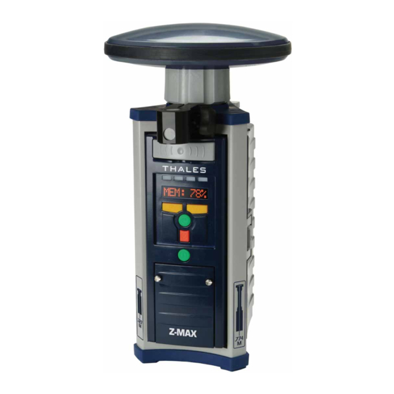
Figure 1.1 Z-Max Surveying System
25
Functional Description
26
Receiver Memory
27
Technical Specifications
27
Table 1.1 Technical Specifications
27
Receiver Options
28
Table 1.2 Receiver Firmware Options
28
Table 1.3. Option 3 Observables
30
Chapter 2 Equipment Description
32
GPS Receiver Module
32
Figure 2.1 GPS Receiver Module
33
Figure 2.2 Z-Max Front Panel
34
Front Panel
34
Figure 2.3 LED Indicator Lights
35
Figure 2.4 Front Panel Display and Control Keys
36
Figure 2.5 SD Memory Card Slot and USB Port
38
Figure 2.6 SD Memory Card
39
Figure 2.7 Z-Max Rear Panel
40
Rear Panel
40
GPS Antenna Module
41
Figure 2.8 GPS Antenna Module
41
Power Module
42
Figure 2.9 Z-Max Power Module
42
Charging
43
Figure 2.10 Connecting the Power Module to the GPS Receiver Module
43
Conditioning
44
Figure 2.11 Power Module and Battery Charger
44
Disposition
46
Communication Module
46
Figure 2.12 Communication Module
46
Figure 2.13 Connecting Communication Module to GPS Receiver Module
48
UHF Antenna Module
49
Figure 2.14 GSM Antenna and SIM Card Slot
49
Figure 2.15 Vortex UHF Antenna Module
50
Handheld Computer/Field Application Software
51
Figure 2.16 FAST Portable Data Terminal
51
Chapter 3 Getting Started
54
Figure 3.1. Charging the Power Module
55
Figure 3.2 Connecting Power Module to GPS Receiver Module
56
Figure 3.3 Connecting Communication Module to GPS Receiver Module
57
Figure 3.4 Connecting GPS Antenna Module to GPS Receiver Module
58
Figure 3.5 SD Memory Card Installation
59
Chapter 4 Operation
66
Front Panel User Interface
66
General
66
Figure 4.1 Control Keys
67
Control Keys
68
Table 4.1. Display Mode Control Buttons
68
Table 4.2 Edit Mode Control Buttons
69
Menus
70
Main Menu
70
Figure 4.2 Front Panel User Interface Main Menu Tree
71
Table 4.3. Main Menu Submenus
72
System Information (SYSINFO)
73
Survey Parameters and Status (Survey:mode)
74
Figure 4.3 Survey: RTK Rover Menu
78
Survey Configuration (SURVCONF)
83
Figure 4.4 SURVCONF: RTK Rover Menu
86
Session Control (SESSIONS)
89
Receiver Parameters Settings (SETTINGS)
90
Communication Options (COM OPTN)
91
Figure 4.5 Thales Radio Menu
92
Figure 4.6 PDL Radio Menu
95
Figure 4.7 GSM Rover Menu
97
Figure 4.8 GSM Base Menu
100
Data Recording
102
Setting the Data Recording Interval
102
Data Modes
102
Table 4.4. Data Recording Modes
103
Downloading the Data
104
Downloading the SD Memory Card Data
104
Downloading the Handheld Computer Data
107
Data Files
108
Table 4.5. File Types
108
Figure 4.9 File Naming Convention
109
Warning Messages
111
Table 4.6. Warning Messages
111
SECTION 2 - System Guide to Post-Process Surveying
116
Chapter 1 Introduction
118
The Global Positioning System (GPS)
119
Surveying with GPS
120
Post-Process GPS Surveying
120
Post-Processing GPS Data
121
Applications
122
Limitations
122
Thales Navigation Z-Max System
123
Chapter 2 System Components
124
Hardware
124
Z-Max GPS Receiver Module
124
GPS Antenna Module
125
Figure 2.1 Z-Max GPS Receiver Module
125
Z-Max Power System
126
Figure 2.2 Z-Max Antenna Module
126
Communication Module
127
Figure 2.3 Z-Max Power Module
127
Mounting Accessories
128
Figure 2.4 Z-Max V-Module
128
Figure 2.5 HI Measurement Plate
128
Figure 2.6 Range Pole RF Adapter
129
Figure 2.7 Max-RF Adapter
130
Handheld Computer
131
Figure 2.8 Pole Adapter
131
Figure 2.9 FAST Terminal
132
Z-Max Application Software
133
Field Application Software
133
Office Software
133
Chapter 3 Connecting System Hardware
136
GPS Receiver - GPS Antenna Module
136
GPS Receiver - Receiver Power System
137
Figure 3.1 Connecting GPS Antenna Module to GPS Receiver Module
137
Figure 3.2 Connecting Power Module to GPS Receiver Module
138
Handheld Computer - GPS Receiver
139
Figure 3.3 External Power Port Connection
139
Figure 3.4 FAST Terminal
140
Z-Max System - Tripod/Survey Pole/Backpack
141
Figure 3.5 Static Setup
142
Figure 3.6 Pole-Mounted Rover Setup
143
Figure 3.7 Z-Max Backpack Connectivity
144
Figure 3.8 Backpack-Mounted Rover Setup
145
Chapter 4 Survey Preparation and Execution
146
Figure 4.1 Soft Case
147
Figure 4.2 Inside View of Soft Case
147
Static Surveys
148
Figure 4.3 Conventional and Fixed-Height Tripods
150
Figure 4.4 Measuring HI (Height of Instrument) of GPS Antenna
151
Figure 4.5 Z-Max Survey System Performing a Static Survey
154
Kinematic Surveys
155
Kinematic Survey Setup
155
Figure 4.6 Pole-Mounted Rover System
157
Figure 4.7 Backpack-Mounted Rover System with Survey Pole
158
Figure 4.8 FAST Terminal Handheld Computer Mounted on Rover Pole
159
Kinematic Survey Execution
161
Figure 4.9 Pole-Mounted Rover System Ready to Survey
161
Chapter 5 Troubleshooting
168
GPS Receiver Does Not Track Satellites
169
GPS Receiver Is Not Recording Data
171
SECTION 3 - System Guide to RTK Surveying
174
Chapter 1 Introduction
176
The Global Positioning System (GPS)
177
Real-Time Kinematic Surveying
178
Figure 1.1 RTK Setup for GPS Surveying
178
Applications
179
Limitations
180
Thales Navigation Z-Max
181
About the Guide to RTK Surveying
181
Chapter 2 System Components
182
GPS Receiver and Antenna
183
Figure 2.1 Z-Max GPS Receiver Module
184
Figure 2.2 Pole Mounted Z-Max RTK Receiver
185
Figure 2.3 Backpack Z-Max RTK Receiver
185
Figure 2.4 GPS Antenna Module
186
Data Link
187
Figure 2.5 Z-Max Communications Module
187
Figure 2.6 Thales U-Link Radio
189
Figure 2.7 Pacific Crest PDL Base Transmitter
189
Figure 2.8 GSM Communication Module
191
Power Sources
193
Figure 2.9 UHF Antenna Module and GPS Antenna Module
193
Figure 2.10 Power Module
194
Mounting Accessories
195
Figure 2.11 HI Measurement Plate
195
Figure 2.12 Pole Adapter - Pole-Mounted System
196
Figure 2.13 Range Pole RF Adapter - Backpack Mounted System
197
Handheld Computer/Field Application Software
198
Figure 2.14 Max-RF Adapter
198
Figure 2.15 FAST Terminal
199
Office Software
200
Chapter 3 Hardware Connectivity
202
RTK Base System
202
GPS Receiver - Receiver Power System
202
Figure 3.1 GPS Receiver - Power Module Connection
203
GPS Receiver - GPS Antenna
204
Figure 3.2 External Power Connection
204
GPS Receiver - Communication Module
205
Figure 3.3 GPS Antenna Connection
205
GPS Receiver - Tripod
206
Figure 3.4 Connecting Communication Module to GPS Receiver Module
206
Figure 3.5 GPS Receiver Module and Tripod Adapter
207
Figure 3.6 GPS Receiver Module Fixed Height Tripod Installation
208
Radio - Radio Antenna
209
Figure 3.7 GPS Receiver Module Adjustable Tripod Installation
209
Figure 3.8 Thales U-Link Radio Antenna
210
Figure 3.9 Mounting the Thales U-Link Transmitter
211
GPS Receiver - Radio
212
Figure 3.10 PDL Radio and Radio Antenna
212
Figure 3.11 Connecting PDL 35-W Radio & Z-Max GPS Receiver Module
214
Figure 3.12 Connecting PDL 2-W LPB Radio & Z-Max GPS Receiver Module
215
Figure 3.13 Connecting Thales U-Link Radio & Z-Max GPS Receiver Module
216
Handheld Computer - GPS Receiver
217
Fully Connected RTK Base System
217
Figure 3.14 Z-Max RTK Base with Cellular Modem
218
Figure 3.15 Thales U-Link Radio in RTK Base Configuration
219
Figure 3.16 RTK Base with Thales U-Link Radio
220
RTK Rover System
221
Figure 3.17 Pacific Crest PDL Radio with All Cable Connections
221
Figure 3.18 UHF Antenna Module
222
GPS Receiver - Radio Antenna
222
Pole-Mounted Rover System
222
Figure 3.19 UHF Antenna Connection to GPS Receiver Module
223
GPS Receiver - GPS Antenna
223
Figure 3.20 GPS Antenna Module - UHF Antenna Module Connection
224
GPS Receiver - Communication Module
224
Figure 3.21 Connecting Communication Module to GPS Receiver Module
225
GPS Receiver - Receiver Power System
225
Figure 3.22 GPS Receiver - Power Module Connection
226
Handheld Computer - GPS Receiver
226
Figure 3.23 FAST Terminal Handheld Computer
227
Mounting the System to the Pole
227
Backpack-Mounted Rover System
228
Figure 3.24 Fully Connected Pole-Mounted Rover System
228
Fully Connected Z-Max Rover System
228
Figure 3.25 Connecting Communication Module to GPS Receiver Module
229
GPS Receiver - Communication Module
229
GPS Receiver - Receiver Power System
229
Figure 3.26 GPS Receiver - Power Module Connection
230
GPS Receiver - Max-RF Adapter
230
Figure 3.27 Max-RF Adapter and GPS Receiver Module
231
Mount the GPS Receiver Module to the Backpack
231
Figure 3.28 Mounting the Receiver on the Backpack
232
Range Pole RF Adapter - Survey Pole
232
Figure 3.29 Range Pole RF Adapter Connection
233
UHF Radio Antenna
233
Figure 3.30 UHF Antenna/Range Pole RF Adapter Connection
234
GPS Antenna
234
Figure 3.31 GPS Antenna Module - UHF Antenna Module Connection
235
GPS Receiver - Range Pole RF Adapter
235
Figure 3.32 GPS Receiver Module/Range Pole RF Adapter Cable Connection
236
Handheld Computer - GPS Receiver
236
Figure 3.33 FAST Terminal Handheld Computer
237
Figure 3.34 Fully Connected Backpack-Mounted Rover Systems
238
Fully Connected Z-Max Backpack Rover System
238
Chapter 4 RTK Survey Preparation
240
RTK Parameters
240
Data Formats
240
RTK Positioning Modes
241
RTK Logging Modes
243
RTK Position Output
244
Base Station Position
244
Antenna Reduction
245
Base System Setup
246
Select Appropriate Base System Site
246
Position Tripod over Base Point
246
Mount the Base Radio and Antenna
247
Figure 4.1 Conventional and GPS Tripods
247
Figure 4.2 Mounted Thales Base Radio and Antenna
248
Figure 4.3 Mounted PDL Base Radio Antenna
249
Connect System Components
250
Mount the Base System
250
Measure Instrument Height (HI) of GPS Antenna
250
Power up Base System
251
Configure Base GPS Receiver to Function as RTK Base
251
Figure 4.4 Measuring HI (Height of Instrument) of Base GPS Antenna
251
Enter Base Station Site ID, Coordinates, and HI into Base Receiver
252
Configure the Base Data Link
252
Verify Base Receiver Function
254
Figure 4.5 Base System Ready to Survey
254
Rover System Setup
255
Connect System Components
255
Compute the GPS Antenna Instrument Height (HI)
257
Power up Rover System
257
Configure the Rover GPS Receiver to Function as an RTK Rover
257
Configure the Rover Data Link
258
Verify Function
260
Figure 4.6 Backpack Rover System Ready to Survey
261
Figure 4.7 Pole-Mounted Rover System Ready to Survey
262
Chapter 5 Executing an RTK Survey
264
RTK Rover Initialization
264
Performing an RTK Survey
266
Downloading the Data
272
Chapter 6 Troubleshooting
276
Base System Troubleshooting
277
GPS Receiver Does Not Track Satellites
277
Base System Does Not Transmit Data
279
Rover System Troubleshooting
283
GPS Receiver Does Not Track Satellites
283
Radio Not Receiving Data Transmitted by Base
283
Rover System Is Not Computing a Position
286
Rover Computing Positions with High Uncertainties
289
Appendix A Serial & Power Port Pinouts
292
Figure A.1. Power Receptacle Front View
292
Figure A.2. Serial Port Pin Layout
293
Table A.2 Pinout of Serial Port a
293
Table A.3 Pinout of Serial Port B
294
Table A.4 Pinout of USB Connector
294
Table A.1 Power Connector Pinouts
292
Appendix B User Parameters
296
Table B.1User Parameters
296
Appendix C Uploading New Firmware
298
Appendix D Technical Support
302
Index
304
Email Professionalsalesemea@Thalesnavigation.com
306
Advertisement
Advertisement
Related Products
Thales Z-Max.Net
Thales C17004DA02
Thales C17004DA04
Thales C17004HA02
Thales C17004HA04
Thales C17004PA01
Thales C17004PA03
Thales CGRS
Thales DVOR 432
Thales F9111
thales Categories
Network Hardware
GPS
Turntable
Server
Security System
More thales Manuals
Login
Sign In
OR
Sign in with Facebook
Sign in with Google
Upload manual
Upload from disk
Upload from URL