
Related Manuals for Omron NX-SL3300


Summary of Contents for Omron NX-SL3300
- Page 1 Machine Automation Controller NX-series Safety Control Unit User's Manual NX-SL££££ NX-SI££££ NX-SO££££ Safety Control Unit Z930-E1-13...
- Page 2 Moreover, because OMRON is constantly striving to improve its high-quality products, the infor- mation contained in this manual is subject to change without notice. (3) Every precaution has been taken in the preparation of this manual. Nevertheless, OMRON as- sumes no responsibility for errors or omissions.
-
Page 3: Intended Audience
Introduction Introduction Thank you for purchasing an NX-series Safety Control Unit. This manual contains information that is necessary to use the NX-series Safety Control Unit. Please read this manual and make sure you understand the functionality and performance of the Unit before you attempt to use it in a control system. - Page 4 Introduction NX-series Safety Control Unit User's Manual (Z930)
-
Page 5: Sections In This Manual
Sections in this Manual Sections in this Manual Overview Safety Unit Restore Specifications Safety Data Logging Installation and Wiring Troubleshooting Inspection and Safety Control Unit Maintenance Operation System Configuration Appendices and Setup Index Programming Checking Operation and Actual Operation Calculating Safety Reaction Times Communications Load NX-series Safety Control Unit User's Manual (Z930) -
Page 6: Table Of Contents
CONTENTS CONTENTS Introduction ......................1 Intended Audience............................1 Applicable Products ............................1 Sections in this Manual ................... 3 Relevant Manuals....................11 Manual Structure....................13 Page Structure...............................13 Special Information ............................14 Precaution on Terminology ..........................14 Terms and Conditions Agreement................ 15 Warranty, Limitations of Liability ........................15 Application Considerations ..........................16 Disclaimers ..............................16 Safety Precautions.................... - Page 7 CONTENTS 1-2-4 Types of Safety Control Unit ....................1 - 11 Support Software .......................1 - 12 1-3-1 Applicable Support Software ....................1 - 12 1-3-2 Connection Method and Procedures for EtherCAT Coupler Units ..........1 - 12 1-3-3 Connection Method and Procedures for EtherNet/IP Coupler Units ........1 - 14 Commissioning Procedures .....................1 - 15 1-4-1 Overall Procedure ........................1 - 15...
- Page 8 CONTENTS Section 5 System Configuration and Setup Configuration and Setup Procedures ................5 - 2 Part Names and Functions of the Sysmac Studio Window ..........5 - 3 Controller Configuration and Setup of the Safety Control Units ........5 - 5 5-3-1 Procedures for Creating the Controller Configuration for Safety Control ........5 - 6 5-3-2 Setting and Viewing the Safety Control Unit Settings ...............5 - 9 5-3-3...
- Page 9 CONTENTS 6-5-2 Registering POUs ........................6 - 27 6-5-3 Registering Variables ......................6 - 36 6-5-4 FBD Programming ........................6 - 41 6-5-5 Function Block Conversion for Programs................6 - 60 6-5-6 Building ..........................6 - 61 6-5-7 Searching and Replacing ......................6 - 63 6-5-8 Safety Task Settings........................6 - 66 Automatic Programming ....................6 - 68 6-6-1...
- Page 10 CONTENTS 7-11 Uploading Configuration Information and Safety Application Data ......7 - 60 7-11-1 Outline .............................7 - 60 7-11-2 Uploading Data for a Connection to an NJ/NX-series CPU Unit ..........7 - 60 7-11-3 Uploading Data for a Connection to a Communications Coupler Unit ........7 - 61 7-12 Transferring Safety Application Data................7 - 63 7-13 Monitoring Controller Status ....................7 - 64 7-14 Restarting and Clearing All Memory ................7 - 66...
- Page 11 NX Objects........................... A - 5 A-2-1 Format of NX Object Descriptions.................... A - 5 A-2-2 Safety CPU Unit (NX-SL3300/NX-SL3500) ................A - 5 A-2-3 Safety CPU Unit (NX-SL5500/NX-SL5700) ................A - 7 A-2-4 NX-SID800 Safety Input Unit ....................A - 11 A-2-5 NX-SIH400 Safety Input Unit ....................
- Page 12 CONTENTS I/O Ports of Safety I/O Units ..................... A - 74 A-6-1 NX-SIH400 Safety Input Unit ....................A - 74 A-6-2 NX-SID800 Safety Input Unit ....................A - 76 A-6-3 NX-SOH200 Safety Output Unit ..................... A - 77 A-6-4 NX-SOD400 Safety Output Unit ..................... A - 78 CIP Response Codes......................
-
Page 13: Relevant Manuals
Relevant Manuals Relevant Manuals The following table provides the relevant manuals for this product. Read all of the manuals that are relevant to your system configuration and application before you use the product. Most operations on this product are performed from the Sysmac Studio Automation Software. For de- tails on the Sysmac Studio, refer to the Sysmac Studio Version 1 Operation Manual (Cat. - Page 14 Relevant Manuals Purpose of use NX-SL5£££ Safety CPU Unit NX-SL3£££ Safety CPU Unit NX-SI££££ and NX-SO££££ Safety I/O Units NX-CSG£££ Communication Control Unit NX-series Safety Control Unit User's Manual (Z930)
-
Page 15: Manual Structure
Manual Structure Manual Structure Page Structure The following page structure is used in this manual. Level 1 heading 4 Installation and Wiring Level 2 heading Mounting Units Level 3 heading Level 2 heading Gives the current Level 3 heading headings. 4-3-1 Connecting Controller Components The Units that make up an NJ-series Controller can be connected simply by pressing the Units together... -
Page 16: Special Information
Manual Structure Special Information Special information in this manual is classified as follows: Precautions for Safe Use Precautions on what to do and what not to do to ensure safe usage of the product. Precautions for Correct Use Precautions on what to do and what not to do to ensure proper operation and performance. Additional Information Additional information to read as required. -
Page 17: Terms And Conditions Agreement
Omron’s exclusive warranty is that the Products will be free from defects in materials and work- manship for a period of twelve months from the date of sale by Omron (or such other period ex- pressed in writing by Omron). Omron disclaims all other warranties, express or implied. -
Page 18: Application Considerations
WAY CONNECTED WITH THE PRODUCTS, WHETHER SUCH CLAIM IS BASED IN CONTRACT, WARRANTY, NEGLIGENCE OR STRICT LIABILITY. Further, in no event shall liability of Omron Companies exceed the individual price of the Product on which liability is asserted. Application Considerations... - Page 19 Product. Errors and Omissions Information presented by Omron Companies has been checked and is believed to be accurate; how- ever, no responsibility is assumed for clerical, typographical or proofreading errors or omissions. NX-series Safety Control Unit User's Manual (Z930)
-
Page 20: Safety Precautions
Safety Precautions Safety Precautions Definition of Precautionary Information The following notation is used in this manual to provide precautions required to ensure safe usage of the NX-series Safety Control Unit. The safety precautions that are provided are extremely important to safety. -
Page 21: Warnings
Safety Precautions Warnings Serious injury may possibly occur due to loss of required safety functions. When building the system, observe the following warnings to ensure the integrity of the safety-related components. WARNING Setting Up a Risk Assessment System The process of selecting these products should include the development and execu- tion of a risk assessment system early in the design development stage to help identify potential dangers in your equipment and optimize safety product selection. - Page 22 Safety Precautions Installing Safety Products Qualified engineers must develop your safety-related system and install safety prod- ucts in devices and equipment. Prior to machine commissioning verify through testing that the safety products works as expected. Related International Standards: • ISO 12100 General Principles for Design - Risk Assessment and Risk Reduction •...
- Page 23 Safety Precautions Confirm that the calculated reaction times meet the required specifications for all safety chains. Serious injury may possibly occur due to loss of required safety functions. All safety devices and components that are connected to an NX-series Safety Control Unit must be selected and used to meet the required level of safety and the relevant safety category.
- Page 24 Safety Precautions After you perform safety validation, check items for safety validation printed out to con- firm Safety Control Units are correctly configured. Although the Simulator and Simple Automatic Test simulate the operation of the Safety CPU Unit, there are differences from the Safety CPU Unit in operation and timing. Al- ways confirm operation on the actual equipment before you operate the equipment.
- Page 25 Safety Precautions Transferring Always confirm safety at the destination before you transfer the unit configuration infor- mation, parameters, set values, or other data from tools such as the Sysmac Studio. The devices or machines may perform unexpected operation regardless of the operat- ing mode of the Controller.
-
Page 26: Precautions For Safe Use
Precautions for Safe Use Precautions for Safe Use Transporting • Do not attempt to disassemble, repair, or modify any Units. Doing so may result in malfunction or fire. • Do not drop any Unit or subject it to abnormal vibration or shock. Doing so may result in Unit mal- function or burning. - Page 27 Precautions for Safe Use Restricted region (shaded portion) • For the installation orientations in the following figure, support the cables, e.g., with a duct, so that the End Plate on the bottom is not subjected to the weight of the cables. The weight of the cables may cause the bottom End Plate to slide downward so that the Slave Terminal is no longer secured to the DIN Track, which may result in malfunctions.
- Page 28 Precautions for Safe Use • When you insert a flat-blade screwdriver into a release hole on the screwless clamping terminal block, press the screwdriver down with a force of 30 N or less. Applying excessive force may dam- age the terminal block. •...
- Page 29 Precautions for Safe Use • Make sure that the voltages and currents that are input to the Units and slaves are within the speci- fied ranges. Inputting voltages or currents that are outside of the specified ranges may damage the Units or slaves or cause fire.
- Page 30 Precautions for Safe Use Unit Replacement • After you replace the Safety Control Unit, set the program and all configuration settings that are nec- essary to resume operation. Make sure that the safety functions operate normally before you start actual operation. •...
-
Page 31: Precautions For Correct Use
Precautions for Correct Use Precautions for Correct Use Storage and Installation • Follow the instructions in this manual to correctly perform installation and wiring. • Do not operate or store the Units in the following locations. Doing so may result in burning, in opera- tion stopping, or in malfunction. - Page 32 Safety CPU Unit. Take caution not to lose the password. If you want to reset the con- figured password, contact your OMRON representative. • For safety data logging, make sure to use the settings file generated from the same project file as the logging target.
-
Page 33: Regulations And Standards
NRAQ7 (CSA C22.2 No. 61010-1, and CSA C22.2 No. 61010-2-201) FSPC (IEC 61508 and EN ISO 13849) The FSoE protocol was certified for applications in which OMRON FSoE devices are connected to each oth- For compatibility with FSoE devices other than OMRON FSoE devices, the customer must validate FSoE communications. -
Page 34: Conformance To En Iso 13849-1 And En 62061
Use an SELV power supply that meets the requirements of IEC/EN 60950-1 and EN 50178. Do not allow the power supply cable length to exceed 3 m. We recommend that you use the OMRON S8VK-S-series Power Supplies. EMC standard com- pliance was confirmed for the recommended Power Supplies. -
Page 35: Conformance To Ul And Csa Standards
NX-series product must also comply with the standards, consult with your OMRON representative. Application conditions are defined according to the installation location. Application may not be possible for some installation locations. - Page 36 Regulations and Standards Usage Conditions for KC Certification Take the same measures as those described in Conformance to EU Directives on page 31. In addi- tion, attach a clamp core to the port side of the EtherNet/IP cable. The recommended clamp core is given below. Recommended Clamp Core Manufacturer Product...
-
Page 37: Unit Versions
Unit Versions Unit Versions This section describes the notation that is used for unit versions, the confirmation method for unit ver- sions, and the relationship between unit versions and Sysmac Studio versions. Unit Versions A “unit version” refers to a revision number of the respective NX-series Units. A “unit version” has been introduced to manage the Units in the NX Series according to differences in functionality accom- panying Unit upgrades. -
Page 38: Unit Versions Of Units And Sysmac Studio Versions
Gives the unit version of the Unit. Lot number Gives the lot number of the Unit. DDMYY£: Lot number, £: Used by OMRON. “M” gives the month (1 to 9: January to September, X: October, Y: November, Z: December) The following information is provided in the notched area on the Unit. -
Page 39: Related Manuals
Related Manuals Related Manuals The followings are the manuals related. Use these manuals for reference. Manual name Cat. No. Model numbers Application Description NX-series Z930 NX-SL££££ Learning how to use Describes the hardware, setup methods, Safety Control Unit NX-SI££££ NX-series Safety and functions of the NX-series Safety Con- User's Manual NX-SO££££... - Page 40 Related Manuals Manual name Cat. No. Model numbers Application Description NJ/NX-series W506 NX701-££££ Using the built-in Information on the built-in EtherNet/IP port CPU Unit NX102-££££ EtherNet/IP port on is provided. NX1P2-££££ an NJ/NX-series Information is provided on the basic setup, ™...
-
Page 41: Terminology
Terminology Terminology Term Description standard The generic term for devices, functions, and data that are used for general control purposes as opposed to those that are used for safety measures. safety function A function that is executed by the safety control system to achieve a safe state for a machine hazard. - Page 42 Terminology Term Description safety input device An input device that is designed with special safety measures for use in safety controls. The generic term for safety input devices, such as emergency stop pushbutton switches and safety switches. safety output device An output device that is designed with special safety measures for use in safety controls.
- Page 43 Terminology Term Description CPU Rack A Rack to which a CPU Unit or Communication Control Unit is mounted. For NX-series CPU Units to which NX Units can be connected, a CPU Rack has a CPU Unit with NX Units and an End Cover mounted to it.
-
Page 44: Revision History
Corrected mistakes. • July 2015 4-1-2 Calculating the Safety Reaction Time Corrected numeric values for OMRON Special Safety Input Devices that are used when calculating safety sensor/switch response time. • 4-1-2 Calculating the Safety Reaction Time Corrected the calculation method for safety input refresh time and safety out- put refresh time for safety I/O refresh time. - Page 45 Revision History Revision Date Revised content code • October 2016 Made revisions accompanying the upgrade to Sysmac Studio version 1.17. • 6-9-2 Exporting/Importing Data for the Entire NX Unit • 7-5-2 Registering POUs Added program import/export functions. • 8-5 Checking External Device Wiring •...
- Page 46 Revision History NX-series Safety Control Unit User's Manual (Z930)
-
Page 47: Overview
Overview This section introduces and describes the features, system configuration, and applica- tion procedure of the NX-series Safety Control Units. Introduction and Features ................1 - 2 1-1-1 Overview of Safety Control Unit..............1 - 2 1-1-2 Features of Safety Control Unit ..............1 - 5 System Configuration and Configuration Devices ........ -
Page 48: Introduction And Features
1 Overview Introduction and Features 1-1-1 Overview of Safety Control Unit The NX-series Safety Control Units are part of the lineup of Sysmac devices. They are used to exe- cute safety controls. Safety Control Units are classified as NX Units and they are used connected to an NX-seriess, EtherCAT Coupler Unit or EtherNet/IP Coupler Unit. - Page 49 1 Overview Sysmac Studio Setting, programming, and NJ/NX-series debugging the Safety Control Units EtherCAT master EtherCAT slaves Safety Control Units EtherCAT Coupler Unit EtherCAT EtherCAT Coupler Unit EtherCAT slaves, such as servos, vision systems, and I/O When you set up the Safety System configuration on the Sysmac Studio, you automatically achieve safety process data communications (Safety over EtherCAT) on any EtherCAT network that was in- stalled for standard process data communications.
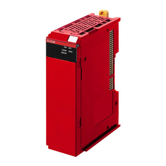
- Page 50 NX-SL3£££ Units. Standalone Safety Control System The NX-SL3300 Unit is used connected to an EtherNet/IP Coupler Unit to achieve safety controls in a Slave Terminal. The Safety Control Unit performs remote I/O communications with a standard controller through an EtherNet/IP Coupler Unit.
-
Page 51: Features Of Safety Control Unit
• Standalone safety control system does not support CIP Safety on EtherNet/IP communica- tions. • The EtherNet/IP Coupler Units support connection of NX-SL3300 Units, NX-SI££££ Units and NX-SO££££ Units. It does not support connection to NX-SL5£££ Units and NX- SL3500 Units. - Page 52 You can easily exchange data between Safety CPU Unit and standard I/O Units. Excellent Connectability with OMRON Safety I/O Devices You can directly connect OMRON’s wide lineup of Safety I/O Devices to Safety I/O Units without using any special units.
- Page 53 1 Overview l Checking Safety Programs and Safety Parameters You can verify beforehand whether your safety programs (user program for safety controls that runs on the Safety CPU Unit) and safety parameters (parameters that are used for safety controls) meet the validity and safety aspects that are outlined below. •...
-
Page 54: System Configuration And Configuration Devices
1 Overview System Configuration and Configura- tion Devices 1-2-1 Safety Control System Configuration on NX bus of CPU Unit or EtherCAT Network In this configuration, the safety control system operates on the NX bus of the NX-series CPU Unit and on the EtherCAT network. - Page 55 EtherCAT network. You can use only one Safety CPU Unit on each EtherCAT net- work. *1. The connectivity of FSoE communications between the OMRON NX-series Safety Control Unit is confirmed using the OMRON 1S-series Servo Driver. You can also mount just a Safety CPU Unit to an EtherCAT Coupler Unit without mounting Safety I/O Units, as shown in the following figure.
-
Page 56: Safety Control System Configuration On Ethernet/Ip Network
1 Overview l Applicable NJ/NX-series CPU Units and NX-series EtherCAT Coupler Unit Refer to A-17 Version Information on page A - 105 for the model numbers and unit versions of the NJ/NX-series CPU Units and the NX-series EtherCAT Coupler Units that can be used together. Precautions for Correct Use If you use an NX-series CPU Unit, you cannot set both the priority-5 periodic task and another task for an EtherCAT Coupler Unit that contains a Safety Control Unit. -
Page 57: Types Of Safety Control Unit
1 Overview Safety Control System in EtherNet/IP Slave Terminals Safety Control System The Safety CPU Unit Safety performs safety process data Coupler Standard Unit communications with the Unit CPU Unit Safety I/O Units in the Slave Terminal. Safety Coupler Coupler Unit Unit Unit... -
Page 58: Support Software
1 Overview Support Software You use the Support Software to set up the safety control system for the Safety Control Unit and to perform programming and debugging. 1-3-1 Applicable Support Software You use the Support Software to set up the safety control system for the Safety Control Unit, and to perform programming and debugging. - Page 59 1 Overview Sysmac Studio NJ/NX-series EtherCAT Communications System Safety control system USB or EtherNet/IP Safety Coupler NJ/NX-series Unit CPU Unit Unit Accessible EtherCAT Coupler Unit Accessible USB connection to the EtherCAT Coupler Unit You can connect the Sysmac Studio to the USB port on the EtherCAT Coupler Unit. This connection allows you to download, upload, and monitor the safety programs for only the Safety CPU Unit and Safety I/O Units that are under the EtherCAT Coupler Unit that the Sysmac Studio is online with.
-
Page 60: Connection Method And Procedures For Ethernet/Ip Coupler Units
1 Overview Functional Differences on the Sysmac Studio Based on the Con- nection Point The functions that you can use on the Sysmac Studio depend on what the Sysmac Studio is connect- ed to. Refer to the NX-series EtherCAT Coupler Unit User’s Manual (Cat. No. W519) for details. 1-3-3 Connection Method and Procedures for EtherNet/IP Coupler Units... -
Page 61: Commissioning Procedures
1 Overview Commissioning Procedures 1-4-1 Overall Procedure Use the following procedure to build a safety system. The procedure is divided into steps for standard control and safety control. Safety Control Standard Control Step 1. System Design Step 1-1 Determining Safety Measures by Performing Risk Assessment Step 1-2 Selecting Safety Devices Step 1-3 Designing the Interface between Standard Controls and Safety Controls Step 2. -
Page 62: Detailed Procedures
1 Overview 1-4-2 Detailed Procedures As described in the previous section, the standard controls and safety controls are linked with one an- other throughout the setup procedures. This section describes the detailed procedures for the safety controls. Refer to NJ/NX-series CPU Unit Software User’s Manual (Cat. No. W501)for the detailed procedures for using NJ/NX-series CPU Units for standard control. - Page 63 1 Overview Step Description Reference Step 2-2 Designing Safety Design the POUs (Program Organization Units). Section 6 Programming on • Programs Programs page 6 - 1 • Function blocks Design of Variables: • Design the data types of the variables (partic- ularly the design of safety data types and standard data types).
- Page 64 1 Overview Step Description Reference Step 4-3 Assigning Safety On the parameter setting tab page for the Safe- 5-5 Safety I/O Functions on I/O Terminals to the Con- ty I/O Units, select the safety I/O devices that page 5 - 23 nected Devices are connected to the safety I/O terminals.
- Page 65 1 Overview Step Description Reference Step 5-4 Connecting the Use one of the following connections. 1-3 Support Software on page • Computer That Runs the Connect a USB cable to the NJ/NX-series 1 - 12 Sysmac Studio Refer to the Sysmac Studio CPU Unit Version 1 Operation Manual •...
- Page 66 1 Overview Step Description Reference Step 7-2 Troubleshooting If an error occurs, use the troubleshooting func- Section 12 Troubleshooting on Errors If They Occur tion of the Sysmac Studio to check the error and page 12 - 1 determine the cause. Then, remove the error. Step 7-3 Inspection and Perform periodic maintenance.
-
Page 67: Specifications
Specifications This section provides the specifications of the Safety CPU Unit and the Safety I/O Units. Safety CPU Unit .................... 2 - 2 2-1-1 Models and Specifications ................2 - 2 2-1-2 Part Names and Functions ................2 - 8 2-1-3 Indicators .................... -
Page 68: Safety Cpu Unit
Maximum Number of number of Program ca- Model safety I/O con- I/O refreshing method safety I/O pacity nections points NX-SL3300 256 points 512 KB Free-Run refreshing NX-SL3500 1,024 points 2,048 KB Free-Run refreshing NX-SL5500 1,024 points 2,048 KB Free-Run refreshing... - Page 69 2 Specifications Item Specification Operating environment Ambient operating tem- 0 to 55°C perature Ambient operating hu- 10% to 95% (with no condensation or icing) midity Atmosphere Must be free from corrosive gases. Ambient storage temper- −25 to 70°C (with no condensation or icing) ature Altitude 2,000 m max.
- Page 70 The number of CIP Safety connections that can be actually set depends on the maximum number of routa- ble CIP Safety connections of the NX-series CPU Unit. For NX102 CPU Units, the maximum number of routable CIP Safety connections is 16. l NX-SL3300 Item Specification...
- Page 71 2 Specifications Item Specification • Connected to a CPU Unit NX Unit power consumption 1.25 W max. • Connected to a Communications Coupler Unit 0.90 W max. Current consumption from I/O power supply No consumption Weight 75 g max. Installation orientation and restrictions Installation orientation: •...
- Page 72 2 Specifications Item Specification Installation orientation and restrictions Installation orientation: • Connected to a CPU Unit Possible in the upright installation orientation. • Connected to a Communications Coupler Unit Six possible orientations. Restriction: None. The cable length for the Units that supply power to the corresponding Unit must be up to 20 m. Only NX102 CPU Units can be connected.
- Page 73 2 Specifications Item Specification Current capacity of I/O power supply No I/O power supply terminals terminal 3.35 W max. NX Unit power consumption Current consumption from I/O power No consumption supply Weight 130 g max. Installation orientation and restric- Installation orientation: Upright installation Restriction: None.
-
Page 74: Part Names And Functions
Only NX102 CPU Units and Communication Control Units can be connected. NX1P2 CPU Units or Commu- nications Coupler Units cannot be connected. 2-1-2 Part Names and Functions This section describes the names and functions of the Safety CPU Unit components. l NX-SL3300 or NX-SL3500 2 - 8 NX-series Safety Control Unit User's Manual (Z930) - Page 75 Letter Name Function Marker attachment loca- The locations where markers are attached. The markers made by OMRON tions are installed for the factory setting. Commercially available markers can also be installed. Refer to 3-1-2 Attaching Markers on page 3 - 4.
-
Page 76: Indicators
Do not use the status of the indicators on the NX-series Safety Control Units for safety operations. This will compromise the safety functions of the Unit and may cause serious injury in the event of an accident. NX-SL3300/SL3500 Letter Name Function Model number display Displays part of the model number of the Safety CPU Unit. - Page 77 2 Specifications Color Status Meaning Lit. A hardware error, WDT error, or other critical error has occurred. Flashing (at 1-s An NX bus communications error, I/O allocation information data error, or intervals) other recoverable minor error that is attributed to the NX bus has occurred. •...
- Page 78 2 Specifications Color Status Meaning Yellow Lit. Operation is in progress in DEBUG mode. Not lit. Operation is in progress in a mode other than DEBUG mode or a fatal fault has occur- red. l VALID Indicator The VALID indicator shows whether safety validation has been performed. The following table lists the possible states for this indicator and what they mean.
- Page 79 2 Specifications Color Status Meaning Green The Unit is operating normally. Flashing (at 2-s intervals) Initialization is in progress (from when the power supply is turned ON until RUN or PROGRAM mode is entered), or I/O allocation information data is being downloaded from the Sysmac Studio.
- Page 80 2 Specifications l P ERR Indicator The P ERR indicator shows the error status of the running program or settings of the Safety CPU Unit. The following table lists the possible states for this indicator and what they mean. Color Status Meaning The safety program, CIP Safety communications, and...
- Page 81 2 Specifications Color Status Meaning Yellow Safety application data from the execution of the safety vali- dation is stored in the non-volatile memory. Not lit Safety application data from the execution of the safety vali- dation is not stored in the non-volatile memory, or a fatal fault has occurred.
-
Page 82: Safety Input Unit
2-2-1 Models and Specifications The Safety Input Unit specifications are described below. Models The following table specifies the list of Safety Input Unit models. Number Number OMRON Number of Rated of safety of test Internal I/O Special I/O refresh-... - Page 83 Rated input voltage This is the rated input voltage of the Unit. OMRON Special Safety Input De- This tells whether the Unit supports the connection of OMRON Special vices Safety Input Devices (D40A Non-contact Door Switches, E3FS Single Beam Safety Sensors, etc.).
- Page 84 Number of test output points 2 points Internal I/O common PNP (sinking inputs) Rated input voltage 24 VDC (20.4 to 28.8 VDC) OMRON Special Safety Input De- Can be connected. vices Number of safety slave connec- tions 2 - 18...
- Page 85 2 Specifications Item Specification I/O refreshing method Free-Run refreshing External connection terminals Screwless clamping terminal block (8 terminals) Indicators [TS] indicator, [FS] indicator, [IN] indicator, [IN ERR] indicator [IN] indicator [IN ERR] indicator Safety input current 4.5 mA typical Safety input ON voltage 11 VDC min.
- Page 86 Number of test output points 2 points Internal I/O common PNP (sinking inputs) Rated input voltage 24 VDC (20.4 to 28.8 VDC) OMRON Special Safety Input De- Cannot be connected. vices Number of safety slave connec- tions I/O refreshing method...
- Page 87 2 Specifications Item Specification Safety input OFF voltage/OFF 5 VDC max./1 mA max. current Test output type Sourcing outputs (PNP) Test output rated current 50 mA max. Test output ON residual voltage 1.2 V max. (IOV and all output terminals) Test output leakage current 0.1 mA max.
-
Page 88: Part Names And Functions
Letter Name Function Marker attachment loca- The locations where markers are attached. The markers made by OMRON tion are installed for the factory setting. Commercially available markers can also be installed. Refer to 3-1-2 Attaching Markers on page 3 - 4. - Page 89 2 Specifications Terminal Blocks There are two models of screwless clamping terminal blocks: NX-TB£££2 and NX-TB£££1. The following models of Terminal Blocks can be mounted to Safety Input Units. NX-TB£££2 16-terminal type 8-terminal type NX-TB£££1 16-terminal type 8-terminal type 2 - 23 NX-series Safety Control Unit User's Manual (Z930)
-
Page 90: Indicators
2 Specifications Letter Name Function Terminal number The terminal numbers are given by column letters A and B, and row numbers 1 to 8. indications The combination of the "column" and "row" gives the terminal numbers from A1 to A8 and B1 to B8. The terminal number indicators are the same regardless of the number of terminals on the terminal block, as shown above. - Page 91 2 Specifications WARNING Do not use the status of the indicators on the NX-series Safety Control Units for safety operations. This will compromise the safety functions of the Unit and may cause serious injury in the event of an accident. The indicator pattern depends on the number of input points, as shown below.
- Page 92 2 Specifications The following table lists the possible states for this indicator and what they mean. Color Status Meaning Green The Unit is operating normally. Flashing (at 1-s intervals) Initializing, or I/O allocation information data is being down- loaded from the Sysmac Studio. A hardware error, WDT error, or other critical error has oc- curred.
- Page 93 2 Specifications Color Status Meaning Not lit An error has occurred in the safety input terminal. Refer to 12-2-1 Troubleshooting the Main Errors in the Safety CPU Unit on page 12 - 3 for details on the relationship between the errors of the Safety Input Unit and the indicators. 2 - 27 NX-series Safety Control Unit User's Manual (Z930)
-
Page 94: Safety Output Unit
2 Specifications Safety Output Unit This section describes the models and specifications of the Safety Output Units as well as the names and functions of the parts. 2-3-1 Models and Specifications The Safety Output Unit specifications are described below. Models The following table specifies the list of the Safety Output Unit models. - Page 95 2 Specifications Item Specification Operating environment Ambient operating tem- 0 to 55°C perature Ambient operating humid- 10% to 95% (with no condensation or icing) Atmosphere Must be free from corrosive gases. Ambient storage tempera- −25 to 70°C (with no condensation or icing) ture Altitude 2,000 m max.
- Page 96 2 Specifications Item Specification Safety output rated current This is the maximum load current for safety outputs on the Unit. The inrush current of the external connection load must be lower than this value. Safety output ON residual voltage This is the residual voltage when a safety output on the Unit is ON. Safety output OFF residual voltage This is the residual voltage when a safety output on the Unit is OFF.
- Page 97 2 Specifications Item Specification External con- Screwless clamping terminal block (8 terminals) nection termi- nals Indicators [TS] indicator, [FS] indicator, [OUT] indicator, [OUT ERR] indicator [OUT] indicator [OUT ERR] indicator Safety output 1.2 V max. (between IOV and all output terminals) ON residual voltage Safety output...
- Page 98 2 Specifications Item Specification Terminal con- So0 to So1: Safety output terminals nection dia- IOG: I/O power supply 0 V gram Safety Output Unit NX-SOH200 Refer to 4-3-2 Safety Output Function on page 4 - 32 for details. 2 - 32 NX-series Safety Control Unit User's Manual (Z930)
- Page 99 2 Specifications Item Specification Installation Installation orientation: orientation • Connected to a CPU Unit or a Communication Control Unit and restric- Possible in the upright installation orientation. tions • Connected to a Communications Coupler Unit Six possible orientations. Restriction: For upright installation, the ambient temperature is restricted as shown below ac- cording to the total Unit load current.
- Page 100 2 Specifications Item Specification I/O refreshing method Free-Run refreshing External connection ter- Screwless clamping terminal block (8 terminals) minals Indicators [TS] indicator, [FS] indicator, [OUT] indicator, [OUT ERR] indicator [OUT] indicator [OUT ERR] indicator Safety output ON residual 1.2 V max. (between IOV and all output terminals) voltage Safety output OFF residu- 2 V max.
-
Page 101: Part Names And Functions
2 Specifications Item Specification Terminal connection dia- So0 to So3: Safety output terminals gram IOG: I/O power supply 0 V Safety Output Unit NX-SOD400 Refer to 4-3-2 Safety Output Function on page 4 - 32 for details. Installation orientation Installation orientation: and restrictions •... - Page 102 Letter Name Function Marker attachment loca- The locations where markers are attached. The markers made by OMRON tion are installed for the factory setting. Commercially available markers can also be installed. Refer to 3-1-2 Attaching Markers on page 3 - 4.
- Page 103 2 Specifications 8-terminal type Letter Name Function Terminal number The terminal numbers are given by column letters A and B, and row numbers 1 to 8. indications The combination of the "column" and "row" gives the terminal numbers from A1 to A8 and B1 to B8.
-
Page 104: Indicators
2 Specifications Terminal block Unit model number Model Number of terminals Ground terminal mark Current capacity NX-SOH200 NX-TBA081 8 Not provided NX-TBA082 10 A NX-SOD400 NX-TBA081 8 Not provided NX-TBA082 10 A Precautions for Correct Use You can mount either NX-TB£££1 or NX-TB£££2 Terminal Blocks to the Units that the cur- rent capacity specification of the terminals is 4 A or less. - Page 105 2 Specifications The following section describes the specifications of each indicator. OUT ERR OUT ERR l TS Indicator The TS indicator shows the current status of the Safety Output Unit and its communications status with the NX Bus Master. The following table lists the possible states for this indicator and what they mean. Color Status Meaning...
- Page 106 2 Specifications l OUT Indicator The OUT indicator shows the signal input status of the safety output terminal. The following table lists the possible states for this indicator and what they mean. Color Status Meaning Yellow Safety output terminal is ON and there are no errors. Not lit Safety output terminal is OFF or an error has occurred.
-
Page 107: Pfh
This section gives the PFH (PFH ) values of the NX-series Safety CPU Unit and the Safety I/O Units. Precautions for Correct Use Go to the following URL for the most recent PFH values: http://www.ia.omron.com/support/ sistemalibrary/index.html Additional Information The NX-series Safety Control Unit is a Type B subsystem that is defined by IEC 61508 with HFT = 1 and SFF >... - Page 108 2 Specifications 2 - 42 NX-series Safety Control Unit User's Manual (Z930)
-
Page 109: Installation And Wiring
Installation and Wiring This section describes how to install and wire the Safety Control Units. Installing Units....................3 - 2 3-1-1 Installing NX Units ..................3 - 2 3-1-2 Attaching Markers..................3 - 4 3-1-3 Removing Units .................... 3 - 5 3-1-4 Installation Orientation .................. -
Page 110: Installing Units
3 Installation and Wiring Installing Units The NX-series Safety Control Units are installed in the same way as the NX Units. This section de- scribes how to install and remove NX Units and how to attach markers. Refer to the user's manual of the NX bus master, that the Safety Control Unit is to be connected to, for details on preparations for installation, installation in a control panel, etc. - Page 111 3 Installation and Wiring Precautions for Correct Use • When you install an NX Unit, do not touch or bump the pins in the NX bus connector. • When you handle an NX Unit, be careful not to apply any stress to the pins in the NX bus connector.
-
Page 112: Attaching Markers
Attaching Markers You can attach markers to the NX Units and to the terminal blocks to identify them. The plastic markers made by OMRON are installed for the factory setting. The ID information can be written on them. Commercially available markers can also be installed. -
Page 113: Removing Units
UC1-TMF8 DEK 5/8 Special marker printer UM EN BLUEMARK X1 PrintJet PRO The markers made by OMRON cannot be printed on with commercially available special printers. 3-1-3 Removing Units Precautions for Safe Use Always turn OFF the Unit power supply and I/O power supply before you remove the NX Unit. -
Page 114: Installation Orientation
3 Installation and Wiring Protrusion for removing the Unit Protrusion for removing the Unit Precautions for Correct Use • To remove an NX Unit, remove multiple NX Units together including the one you need to re- move. If you attempt to remove only one NX Unit, it may be tight and difficult to pull out. •... - Page 115 3 Installation and Wiring (A) is the upright installation orientation and (B) to (F) are installation orientations other than upright. Upper Lower However, there are restrictions on the installation orientation and restrictions to the specifications that can result from the Communications Coupler Units and NX Units that are used. For detailed restrictions, refer to the user’s manuals for the Communications Coupler Units, NX Units, and NX-series System Units that you will use.
-
Page 116: Power Supply Types And Wiring
3 Installation and Wiring Power Supply Types and Wiring There are the following two types of power supplies that supply power to the NX Units. Power supply Description type Unit power supply This power supply is used for operating the NX Units. I/O power supply This power supply is used for driving the I/O circuits of the NX Units and for the connected external devi- ces. -
Page 117: Calculating The Total Current Consumption From I/O Power Supply
Refer to the NX-series System Unit User's Manual (Cat. No. W523) for the specifications of these Units. For a complete list of the latest power supply Units in the NX-series, refer to the product catalog or OMRON websites, or contact your OMRON representatives. 3-2-2 Calculating the Total Current Consumption from I/O Power Sup-... -
Page 118: Wiring The Terminals
3 Installation and Wiring Wiring the Terminals This section provides information on wiring the terminals on Safety I/O Units. WARNING Make sure that the voltages and currents that are input to the Units and slaves are within the specified ranges. Inputting voltages or currents that are outside of the specified ranges may cause accidents or fire. - Page 119 3 Installation and Wiring l Using Ferrules If you use ferrules, attach the twisted wires to them. Observe the application instructions for your ferrules for the wire stripping length when attaching ferrules. Precautions for Correct Use Always use plated one-pin ferrules. Do not use unplated ferrules or two-pin ferrules. The applicable ferrules, wires, and crimping tools are given in the following table.
- Page 120 3 Installation and Wiring 8 to 10 mm 1.6 mm max. (except ground terminals) 2.0 mm max. (ground terminals) 2.4 mm max. (except ground terminals) 2.7 mm max. (ground terminals) l Using Twisted or Solid Wires If you use twisted wires or solid wires, use the following table to determine the correct wire specifi- cations.
- Page 121 3 Installation and Wiring Additional Information If more than 2 A will flow on the wires, use plated wires or use ferrules. l Securing Wires It is necessary to secure wires to the screwless clamping terminal block depending on the wire types that are used or the current flows on the wires.
- Page 122 3 Installation and Wiring Hole for securing wires Cable tie Bundle the wires with a cable tie and secure them to the screwless clamping terminal block. Secure wires within the range of 30 mm from the screwless clamping terminal block. 30 mm 3 - 14 NX-series Safety Control Unit User's Manual (Z930)
- Page 123 3 Installation and Wiring Connecting and Removing Wires This section describes how to connect and remove wires. l Terminal Block Parts and Names Release hole Terminal hole l Required Tools Use a flat-blade screwdriver to connect and remove wires. Use the following flat-blade screwdriver. Side view Front view 8°...
- Page 124 3 Installation and Wiring l Connecting Twisted Wires/Solid Wires Use the following procedure to connect the twisted wires or solid wires to the terminal block. Press the flat-blade screwdriver diagonally into the release hole. The optimal angle for insertion is between 10° to 15°. If you press in the screwdriver correctly, you will feel the spring in the release hole.
- Page 125 3 Installation and Wiring Precautions for Safe Use • Do not press the flat-blade screwdriver straight into the release hole. Doing so may break the terminal block. • When you insert a flat-blade screwdriver, press it down with a force of 30 N or less. Applying excessive force may damage the terminal block.
- Page 126 3 Installation and Wiring Wire Remove the flat-blade screwdriver from the release hole. Precautions for Safe Use • Do not press the flat-blade screwdriver straight into the release hole. Doing so may break the terminal block. • When you insert a flat-blade screwdriver into a release hole, press it down with a force of 30 N or less.
- Page 127 3 Installation and Wiring Lock lever Terminal block Attaching a Terminal Block Mount the terminal block hook that is applicable to each Unit model on the guide at the bottom of the NX Unit, lift up the terminal block, and press in on the top of the terminal block until you hear it engage.
- Page 128 3 Installation and Wiring Preventing Incorrect Attachment of Terminal Blocks In order to prevent unintentionally installing the wrong terminal block, you can limit the combination of a Unit and a terminal block. Insert three Coding Pins (NX-AUX02) into three of the six incorrect attachment prevention holes on the Unit and on the terminal block.
- Page 129 1 through 6 in the figure below. As shown in the following table, there are 20 unique pin patterns that you can use. Terminal block Unit Holes used by Holes used by OMRON OMRON Holes for incorrect Holes for incorrect attachment prevention attachment prevention...
- Page 130 • The holes not designated by the numbers 1 through 6 in the above figure are used by OM- RON. If you insert any Coding Pins into the holes reserved for use by OMRON, you will not be able to mount the terminal block to the Unit.
-
Page 131: Checking Wiring
3 Installation and Wiring Unit 3-3-2 Checking Wiring For Input Units, you can turn ON and OFF an input from the external device that is connected to the Unit you need to check and monitor the results. For Output Units, you can use forced refreshing to control the I/O outputs to the Unit you need to check to confirm the operation of the connected external device. - Page 132 3 Installation and Wiring 3 - 24 NX-series Safety Control Unit User's Manual (Z930)
-
Page 133: Safety Control Unit Operation
Safety Control Unit Operation This section provides information that is necessary to use the Safety Control Unit, in- cluding how the Safety Control Unit works. Relationship between Units and Types of Communications ....4 - 2 4-1-1 Safety Control System on CPU Rack or EtherCAT Network ......4 - 2 4-1-2 Safety Control System on EtherNet/IP Network ........... -
Page 134: Relationship Between Units And Types Of Communications
4 Safety Control Unit Operation Relationship between Units and Types of Communications This section describes the relationships between Units and communications between Units in safety control systems that use CPU Units, EtherCAT Coupler Units and EtherNet/IP Coupler Units. 4-1-1 Safety Control System on CPU Rack or EtherCAT Network The section describes the relationships of the Safety CPU Unit, Safety I/O Units, and a standard CPU Unit within the system, and provides details on communications between the Units based on the fol- lowing figure. - Page 135 • Safety I/O Unit on the same CPU rack or the same Slave Terminal • Safety I/O Unit on the Slave Terminal on the EtherCAT network • EtherCAT slave with the FSoE slave function on the EtherCAT network (OMRON 1S-series Servo Driver) In the example above, the Safety CPU Unit operates as a master of safety process data communica- tions.
-
Page 136: Safety Control System On Ethernet/Ip Network
4 Safety Control Unit Operation 4-1-2 Safety Control System on EtherNet/IP Network The section describes the relationships of the Safety CPU Unit, CIP Safety on EtherNet/IP device, and standard CPU Units within the system, and provides details on communications between the Units based on the following figure. - Page 137 4 Safety Control Unit Operation • The Safety CPU Unit connected to another NX-series CPU Unit • CIP Safety on EtherNet/IP-compatible devices To explain the operation better, the originator is referred to as “master” and the target is referred to as “slave”in this section, although the originator/target model is adopted for CIP Safety.
-
Page 138: Standalone Safety Control System
4 Safety Control Unit Operation 4-1-3 Standalone Safety Control System The section describes the relationships of the Safety CPU Unit, EtherNet/IP Coupler Unit, and a stand- ard CPU Unit within the system, and provides details on communications between the Units based on the following figure. - Page 139 4 Safety Control Unit Operation The Safety CPU Unit performs safety process data communications with the Safety I/O Units on the same Slave Terminal. Safety process data communications are not performed with Safety I/O Units on other Slave Terminals on the EtherNet/IP network. Here, the Safety CPU Unit operates as the master in the safety process data communications.
-
Page 140: I/O System
4 Safety Control Unit Operation I/O System This section describes how the Safety CPU Unit processes I/O with external devices such as Safety I/O Units. When the Safety CPU Unit exchanges signals with Safety I/O Units and other external devices, it does so through logical interfaces that are called "I/O ports". -
Page 141: Specifying Safety Data Types And Standard Data Types
4 Safety Control Unit Operation The names of safety data type variables have the word SAFE appended to a standard data type name such as SAFEBOOL and SAFEBYTE. Refer to 6-2-5 Data Type on page 6 - 14 for details on the safety data types. Standard Data Type Variables These variables represent data that is not related to safety controls. -
Page 142: Safety I/O Function
Semiconductor Output for Dual Channel Equivalent • Semiconductor Output for Dual Channel Complementary The following OMRON Special Safety Input Devices can be connected directly without a special con- troller. (This applies only to the NX-SIH400.) 4 - 10 NX-series Safety Control Unit User's Manual (Z930) - Page 143 4 Safety Control Unit Operation Type Examples OMRON Single-beam Safety Sensors E3ZS and E3FS * Conforms to Type 2 and PLc. OMRON Non-contact Door Switches D40Z * Conforms to PLe and Safety Category 4. D40A * Conforms to PLd and Safety Category 3.
- Page 144 4 Safety Control Unit Operation NX-SI Example of Sysmac Studio Settings: • Dual-channel Input When I/O Short Detection between Lines Is Not Required NX-SI Example of Sysmac Studio Settings: 4 - 12 NX-series Safety Control Unit User's Manual (Z930)
- Page 145 4 Safety Control Unit Operation • Dual-channel Input When I/O Short Detection between Lines Is Required NX-SI Example of Sysmac Studio Settings: 4 - 13 NX-series Safety Control Unit User's Manual (Z930)
- Page 146 4 Safety Control Unit Operation Precautions for Correct Use • Configure dual-channel inputs with safety input terminals on the same Unit. It is not always possible to detect short circuits between safety input terminals on different Units. • The total length of cable connected to one test output must be as follows: NX-SIH400 and NX-SID800: 400 m max.
- Page 147 30 µs max. Check the specifications of the connected device for the maximum cable length. l E3ZS/E3FS Single-beam Safety Sensors An OMRON E3ZS/E3FS Single-beam Safety Sensor is connected as shown in the following figure. Single-beam Safety Sensors 24 VDC The unit that supplies the I/O...
- Page 148 4 Safety Control Unit Operation 4 - 16 NX-series Safety Control Unit User's Manual (Z930)
- Page 149 4 Safety Control Unit Operation Precautions for Correct Use • The maximum number of connections per Unit is as follows: NX-SIH400: 4 • You can branch the connections to up to four Single-beam Safety Sensors for each test out- put. Single Beam Single Beam Single Beam...
- Page 150 4 Safety Control Unit Operation l D40A/D40Z Non-contact Door Switches The non-contact door switch output (black line) from the OMRON D40A or D40Z Non-contact Door Switch is input to a safety input terminal. This is a one-line signal. When connecting it, branch it as shown at Si0 and Si1 in the following figure.
- Page 151 • The D40Z Non-contact Door Switch can be used in a Safety Category 4 or lower or a PLe or lower application. l UM/UMA Safety Mats OMRON UM/UMA Safety Mats are connected as shown in the following figure. n pcs (n=12 max.) NX-SIH400...
- Page 152 • The UM/UMA Safety Mats can be used in a Safety Category 3 or lower or a PLd or lower application. They cannot be used in a Safety Category 4 or PLe application. l SGE Safety Edges OMRON SGE Safety Edges are connected as shown in the following figure. 4 - 20 NX-series Safety Control Unit User's Manual (Z930)
- Page 153 4 Safety Control Unit Operation NX-SIH400 n Units (n = 5 max.) Blue Blue Blue Blue Safety edge Brown Brown Brown Brown n + 1 Example of Sysmac Studio Settings: 4 - 21 NX-series Safety Control Unit User's Manual (Z930)
- Page 154 4 Safety Control Unit Operation Precautions for Correct Use • The maximum number of connections per Unit is as follows: NX-SIH400: 5 (5 connected in series × 1 series) • You can connect up to five Safety Eddges to the two test output terminals. •...
- Page 155 4 Safety Control Unit Operation Safety Input Unit Safety CPU Unit Safety Output Unit Safety output Safety input Safety I/O Safety I/O Safety program function function communications execution communications Safety input data Safety output data Self-diagnosis Without test pulse Mechanical contacts Test Pulse Evaluation Single-beam safety sensors A pulse is output at a specific...
- Page 156 An OMRON D40A/D40Z Non-contact Door Switch is connected. Test signals for the D40A Door Switch or D40Z will be output. Safety Mat/Safe- An OMRON UM/UMA Safety Mat or SGE Safety Edge (4-wire) is connected. A test signal ty Edge for Safety Mat/Safety Edge diagnosis is output. Dual Channel Evaluation Safety input terminals can be used as dual channels (one pair).
- Page 157 4 Safety Control Unit Operation Safety CPU Unit Safety Input Unit Test Pulse Evaluation Safety input data Dual channel Safety program evaluation execution Safety process data Test Pulse Evaluation communications The following parameters are also used. • Single/Dual • Discrepancy Time l Single/Dual Set the evaluation method to use with the safety input terminals.
- Page 158 4 Safety Control Unit Operation Input signals on the safe- Safety input data ty input terminals Single/Dual Meaning of status Si (n) Si (n+1) Si (n) Si (n+1) Dual Channel Equivalent 0 Inactive (OFF) Discrepant status Discrepant status Active (ON) Dual Channel Comple- Discrepant status mentary...
- Page 159 4 Safety Control Unit Operation Safety input terminals Error Cause of error detected removed Safety input data I/O indicator (yellow) I/O indicator (red) *1. This is the time that the error status (control data, status data, and indicator status) is held (1 s min.). •...
- Page 160 4 Safety Control Unit Operation Safety input terminal 0 Safety input terminal 1 Safety input data 0 before dual evaluation Safety input data 1 before dual evaluation Discrepancy time Safety input data 0 I/O indicator (yellow) 0 I/O indicator (yellow) 1 I/O indicator (red) 0 I/O indicator (red) 1 *1.
- Page 161 4 Safety Control Unit Operation Setting Error detection Contact Short with posi- circuits Single/Dual Test pulse Disconnection Ground fault tive side of in input power line wiring Dual Channel Without Test Pulse Not detecta- Not detectable. Detectable Not de- Equivalent when input tecta- ble.
- Page 162 4 Safety Control Unit Operation Input Filters The input filter helps prevent malfunctions that are sometimes caused by chattering or noise from the external device that is connected to a safety input terminal. You can filter out chattering and noise from the external device for the widths that are set with the ON delay time and OFF delay time.
- Page 163 4 Safety Control Unit Operation Safety input terminals OFF Error Internal timer Counter cleared. Counter cleared. OFF delay Safety input data I/O indicator (yellow) I/O indicator (red) *1. This is the time that the error status (control data, status data, and indicator status) is held (1 s min.). l Operation with Both an ON Delay and OFF Delay You can filter out ON pulses for the width that is set with the ON delay time and filter out OFF puls- es for the width that is set with the OFF delay time.
-
Page 164: Safety Output Function
4 Safety Control Unit Operation I/O Power Supply Monitoring I/O power supply monitoring monitors the voltage range of the I/O power supply. If a voltage that is less than the specified range is detected, all safety inputs for the Unit are turned OFF. - Page 165 4 Safety Control Unit Operation NX-ECC Current when IOG line is broken I/O power supply (24 VDC) Disconnected. NX-SO Load Use the wiring that is shown in the following figure to prevent a floating condition for the IOG of the Safety Output Unit even if the IOG line is broken.
- Page 166 4 Safety Control Unit Operation NX-SO ≤100m ≤100m ≤100m ≤100m NX-SI Example of Sysmac Studio Settings: Precautions for Correct Use • The line length from the safety output terminals to the output devices (L1, L2, L3, and L4) is 100 m max. for each line. •...
- Page 167 4 Safety Control Unit Operation NX-SO NX-SO Types of Safety Output Functions The types of safety output functions that are performed by the Safety Output Unit is shown below. The safety output functions diagnose the outputs to the safety output terminals and the external device wiring based on the safety output data from the safety program.
- Page 168 4 Safety Control Unit Operation Test Pulse Evaluation The test pulse evaluation outputs a test pulse with a specific period on the 24-VDC power line from a safety output terminal to detect errors in wiring to the externally connected device. This evaluation is achieved through the Test Pulse Diagnosis parameter.
- Page 169 4 Safety Control Unit Operation Setting Description Dual Channel Equiv- The pair of safety output terminals are used as dual channel outputs. The output is ON alent if the paired safety output terminals are both normal. l Relationship between the Single/Dual Setting and Safety Output Data The safety output data that is used in the safety program is output to the safety output terminals according to the Single/Dual parameter as shown below.
- Page 170 4 Safety Control Unit Operation Safety output data Safety output command value Safety output terminals Error Cause detected removed. I/O indicator (yellow) I/O indicator (red) *1. This is the time that the error status (control data, status data, and indicator status) is held (1 s min.). •...
- Page 171 4 Safety Control Unit Operation Safety output data Safety output command value Safety output terminal 0 Error Cause of error detected removed Safety output terminal 1 I/O indicator (yellow) 0 I/O indicator (yellow) 1 I/O indicator (red) 0 I/O indicator (red) 1 Flashing *1.
- Page 172 4 Safety Control Unit Operation Safety Output Terminal Short Detection The safety output terminal short detection prevents the internal circuits of the safety output terminals from being destroyed if an overcurrent flows due to a ground fault or other cause. If an overcurrent is detected, the safety output terminal is turned OFF.
- Page 173 System Configuration and Setup This section describes how to use the Sysmac Studio to configure and set up the safe- ty control system. Configuration and Setup Procedures............5 - 2 Part Names and Functions of the Sysmac Studio Window...... 5 - 3 Controller Configuration and Setup of the Safety Control Units.....
-
Page 174: System Configuration And Setup
5 System Configuration and Setup Configuration and Setup Procedures This section describes the procedures for using the Sysmac Studio to configure and set up the safety control system. Make the settings in the following order. Configure and set up the safety control system. Set up safety process data communications. -
Page 175: Part Names And Functions Of The Sysmac Studio Window
5 System Configuration and Setup Part Names and Functions of the Sys- mac Studio Window This section gives the names of the parts of the Sysmac Studio Window. Use this box to select the Safety CPU Unit or the NJ/NX-series CPU Unit. Controller Selection Box The tab page will change between the Safety CPU Unit Setup and Programming View and the NJ/NX-series CPU Unit Setup and Programming View. - Page 176 5 System Configuration and Setup Item Name Function Output Tab Page The Output Tab Page shows the results of building. Watch Tab Page The Watch Tab Page shows the monitor results of the Simulator or the online Safety CPU Unit. Build Tab Page The Build Tab Page shows the results of program checks and building.
-
Page 177: Controller Configuration And Setup Of The Safety Control Units
5 System Configuration and Setup Controller Configuration and Setup of the Safety Control Units This section describes the Safety Control Unit configuration and setting procedures for the CPU Rack of an NX-series CPU Unit, EtherCAT Slave Terminals and EtherNet/IP Slave Terminals. l CPU Rack or EtherCAT Slave Terminal Configuration and Setting Proce- dures You configure and set up the CPU rack, EtherCAT network and EtherCAT Slave Terminals where... -
Page 178: Procedures For Creating The Controller Configuration For Safety Control
5 System Configuration and Setup EtherNet/IP Coupler Unit In order from left to right: Safety CPU Unit Safety Input Unit Safety Output Unit Digital Input Unit Digital Output Unit 5-3-1 Procedures for Creating the Controller Configuration for Safety Control Use the following procedure to create the Controller configuration for the Safety Control Unit. Procedures for Creating the Controller Configuration for Safety Control Use the following procedure to create the Controller configuration for the Safety Control Units on... - Page 179 5 System Configuration and Setup Click Drag & Drop Perform steps 3 and 4 to add another EtherCAT Coupler Unit. Or, perform step 5 for the EtherCAT Coupler Unit that was added to display the Slave Terminal Tab Page. Select Safety Digital Input Device or Safety Digital Output Device from the Groups List in the Toolbox.
- Page 180 5 System Configuration and Setup Additional Information • You can place only one Safety CPU Unit on a CPU Rack or in the EtherCAT network. If you add more than one Safety CPU Unit, the exclamation icon is displayed under all of the Safety CPU Units, and it will cause an error during the synchronization and download proc- esses.
-
Page 181: Setting And Viewing The Safety Control Unit Settings
5 System Configuration and Setup Additional Information • You can place only one Safety CPU Unit on an EtherNet/IP Slave Terminal. If you add more than one Safety CPU Unit, the exclamation icon is displayed under all of the Safety CPU Units, and it will cause an error during the synchronization and download processes. -
Page 182: Procedure To Change The Model Of The Safety Control Unit
5 System Configuration and Setup Data Item Editing Description Default range Power con- Not pos- The power consumption of the Safety Control Unit Depends on sumption [W] sible. from the NX bus. the model of This setting applies to Units other than an Additional the Unit. - Page 183 5 System Configuration and Setup Select the model or unit version to change to and then click the OK Button. Precautions for Correct Use • Safety validation is not executed when you change the model of a Safety Control Unit. Al- ways execute safety validation again after you change the model.
-
Page 184: Setting Up The Safety Process Data Communications
5 System Configuration and Setup Setting Up the Safety Process Data Communications 5-4-1 Setting Up the FSoE Communications When the Safety Control Unit is placed on the NX bus in the Sysmac Studio CPU rack configuration, EtherCAT network configuration, and EtherCAT slave terminal configuration, the FSoE communica- tions are set up automatically. -
Page 185: Setting Up The Cip Safety Communications
5 System Configuration and Setup Item Editing Description FSoE Possi- This is the setting of the timeout value for FSoE communications between the Safety Watchdog CPU Unit and the Safety I/O Unit. The setting range is from the lowest value of the FSoE watchdog timers to 65,535 ms. Timer WDT auto Possi-... - Page 186 5 System Configuration and Setup Click the button located on the right side of Safety network number (NX bus). The Safety Network Number Settings Dialog Box is displayed. When you click the Auto Option, the Safety Network Number (SNN) is automatically generated from the current time information of the computer on which the Sysmac Studio is running.
- Page 187 5 System Configuration and Setup The Connection Settings (Originator) Tab Page consists of the items shown in the following ta- ble. Item Description EtherNet/IP Port 1 Settings of CIP Safety connections via the built-in EtherNet/IP port 1 are list- Safety Network Number: Specifies the SNN for the EtherNet/IP network for which the port 1 is connected Connection list: Connections grouped together by each target device are list- EtherNet/IP Port 2...
- Page 188 5 System Configuration and Setup Select a target device to open a connection from the Toolbox. Drag and drop it on the connec- tion list for either Port 1 or Port 2 to add the target device and default connection. l Setting the Target Device IP Address Use the following procedure to set the address of the target device to open CIP Safety connection.
- Page 189 5 System Configuration and Setup l Editing Connection Parameters Use the following procedure to edit connection parameters for CIP Safety connections. WARNING If you select “Only Open” for the Open Type setting, make sure to verify that the originator/target have correct configurations. Serious injury may possibly occur due to loss of required safety func- tions.
- Page 190 5 System Configuration and Setup Item Description Network Delay Set the transmission delay time on the network. The default setting is 0 [ms]. Network Reaction Time Value of the connection response performance is shown in ms. This is used in calculating safety reaction time. Specify the connection parameter and click the OK Button.
- Page 191 5 System Configuration and Setup The I/O Assembly Settings (Target) Tab Page consists of the items shown in the following ta- ble. Item Description Active/Inactive Use this box to enable or disable each I/O Assembly. When you ena- ble the assembly, a port is added to the I/O Map. Selected: I/O Assembly is enabled.
-
Page 192: Calculating The Number Of Connections
5 System Configuration and Setup Precautions for Correct Use The I/O Assembly for the Safety CPU Unit cannot be used with the tag data link connection. 5-4-3 Calculating the Number of Connections l Calculating the Number of Safety I/O Connections for the Safety CPU Unit You must specify the total number of CIP Safety originator connections, CIP Safety target connec- tions, and FSoE master connections, which must be set within the number of safety I/O connec- tions that you can set for the Safety CPU Unit. - Page 193 5 System Configuration and Setup For the FSoE master connections, you can establish bidirectional input and output communica- tions with a FSoE slave per connection. • Example of Calculating the Number of Safety I/O Connections A calculation example of using the combination of the NX-series CPU Units and Safety CPU Units is given below.
- Page 194 5 System Configuration and Setup A calculation example of using the combination of the NX-series CPU Units and Safety CPU Units is given below. NX-series Safety NX-series Safety Safety Safety NX-series Safety Safety Safety CPU Unit CPU Unit CPU Unit CPU Unit Input Output...
-
Page 195: Safety I/O Functions
5 System Configuration and Setup Safety I/O Functions You set the safety input functions and safety output functions of the Safety I/O Units when you assign input devices and output devices to the Safety I/O Units with the Sysmac Studio. This section describes how to assign devices that are connected. - Page 196 5 System Configuration and Setup Select a device from the Toolbox to connect to the safety input terminal or safety output termi- nal of the Safety I/O Units, and drag it to the desired I/O terminal. Drag & Drop Enter a comment. When you drag the device to connect to a terminal where it can be dropped, a + mark appears below the mouse cursor as shown below.
- Page 197 5 System Configuration and Setup Refer to 4-3-1 Safety Input Function on page 4 - 10 and 4-3-2 Safety Output Function on page 4 - 32 for the I/O devices that you can connect and the settings for each I/O device. Precautions for Correct Use If you select an input device that cannot be set for a Safety Input Unit, an error will occur and the frame around the input device will be displayed in red.
-
Page 198: Registering Device Variables
5 System Configuration and Setup Registering Device Variables Device variables are used to access data in devices (slaves and Units). This data is accessed through a port that acts as an interface to an external device. This logical port is called an "I/O Port". - Page 199 5 System Configuration and Setup l Selecting from the Registered Variables If the variables that are used in the program are registered before you finalize on the Controller configuration and the external devices to connect, you can select and assign variables to the I/O ports for the safety I/O terminals as long as the variables are registered in the variable table.
- Page 200 5 System Configuration and Setup l NX-SID800 Safety Input Unit Port Data type Name Description fault Si00 Logical SAFE- Si00 Logical Gives the status of safety input terminal Si00. Value BOOL Value 0: OFF, 1: ON Si01 Logical SAFE- Si01 Logical Gives the status of safety input terminal Si01.
- Page 201 5 System Configuration and Setup l NX-SOD400 Safety Output Unit Port Data type Name Description fault Safety Con- SAFE- Safety Con- This flag indicates when a safety connection is nection Status BOOL nection Status active. Use it for an input to the Activate terminal on a safety FB or for safety connection/disconnection applications.
-
Page 202: Exposing Variables To Standard Controllers
5 System Configuration and Setup Exposing Variables to Standard Con- trollers This section describes how to control and monitor a Safety CPU Unit from a standard controller through standard process data communications. 5-7-1 Exposing Global Variables When you set global variables in the Safety CPU Unit for standard process data communications, the variables are exposed as I/O ports in the I/O Map of the CPU Ruck or Communications Coupler Unit. -
Page 203: Setting Exposed Variables
5 System Configuration and Setup 5-7-2 Setting Exposed Variables This section describes how to expose Safety CPU Unit variables to a standard controller. Exposed Safety CPU Unit variables (exposed variables) appear in the I/O Map of the NX Bus Master. Use one of the following methods to set exposed variables. - Page 204 5 System Configuration and Setup Enter the variable name in the Name Column of the output table or input table. The variable that you entered is registered in the exposed variable table and in the global vari- able table. Setting the Expose Column for Global Variables Register global variables with standard data types.
- Page 205 5 System Configuration and Setup Register global variables with standard data types. Refer to 6-5-3 Registering Variables on page 6 - 36 for details on registering variables. Right-click one or more global variables and select Copy from the menu. The selected global variables are copied. Press the Shift Key or Ctrl Key to select more than one global variable.
- Page 206 5 System Configuration and Setup To change the I/O setting for an exposed variable, right-click the exposed variable and select Move To Output or Move To Input from the menu. Press the Shift Key or Ctrl Key to select more than one exposed variable. Selecting Global Variables on the Exposed Variables Tab Page Use the following procedure to select registered global variables on the Exposed Variables Tab Page and set them as exposed variables.
-
Page 207: Safety Cpu Unit Status
5 System Configuration and Setup Enter the name of the variable to expose (the global variable that was registered in step 1) to the NJ/NX-series CPU Unit. You can also enter the first letter of the global variable in the Name Box to display a list of can- didates, and then double-click the desired variable. -
Page 208: I/O Ports For Safety I/O Units
5 System Configuration and Setup l Using an EtherNet/IP Coupler Unit The Safety CPU Unit status is assigned in the I/O Map of the Communications Coupler Unit. You can check the I/O allocation information of Communications Coupler Unit on the Edit I/O Allocation Settings Pane. -
Page 209: Setting Standard Process Data Communications
5 System Configuration and Setup Setting Standard Process Data Com- munications This section describes procedures for using standard process data communications between a Safety CPU Unit and standard I/O Units. 5-8-1 Using an CPU Unit or EtherCAT Coupler Unit For standard process data communications between the Safety CPU Unit and Safety CPU Unit the standard controller exchanges the data between the Safety CPU Unit and standard I/O Units. - Page 210 5 System Configuration and Setup Item Editing Description Exposed Varia- Not possible. The registered exposed variables are displayed. bles Input/Output Not possible. Whether the exposed variable is an input or output variable is dis- played. Data Type Not possible. The data type of the variable is displayed. Comment Not possible.
-
Page 211: Exporting/Importing Settings Data
5 System Configuration and Setup Exporting/Importing Settings Data This section describes how to reuse the settings data for the entire Slave Terminal in the Sysmac Stu- dio or the safety application data in the Safety CPU Unit. You can export and import the data for the entire Slave Terminal or the safety application data in the Safety CPU Unit as a single file. - Page 212 5 System Configuration and Setup Right-click the target EtherCAT Coupler Unit and select Export Slave Settings from the menu. The Save File Dialog Box is displayed. Enter a file name, and then click the Save Button. An EtherCAT slave parameter file with an .ets extension is saved. To import a file, select the Unit above the point where you wish to add the slave on the Ether- CAT Tab Page, and then right-click and select Import Slave Settings and Insert New Slave from the menu.
-
Page 213: Exporting/Importing The Settings For All The Nx Units On A Cpu Rack Or Slave Terminal
5 System Configuration and Setup Additional Information If you distribute multiple Safety Control Unit and set the device names and node addresses for exporting. • Saving the Safety Application Data Place all of the Safety Control Unit on one Slave Terminal and export the settings. Use the Multiview Explorer to move NX Units between Slave Terminals. -
Page 214: Exporting/Importing Data For Individual Safety Cpu Unit
5 System Configuration and Setup Enter a file name, and then click the Save Button. A configuration file for all the NX Units with an .nsfp extension is saved. To import a file, select the CPU Unit on the Edit CPU Rack Configuration Tab Page or select the Communications Coupler Unit on the Slave Terminal Tab Page. - Page 215 5 System Configuration and Setup Right-click the Safety CPU Unit to export and select Export NX Unit Settings from the menu. The Export NX Unit Settings Dialog Box is displayed. Enter a file name, and then click the Save Button. An NX Unit configuration file with an .nsf extension is saved.
- Page 216 5 System Configuration and Setup 5 - 44 NX-series Safety Control Unit User's Manual (Z930)
-
Page 217: Programming
Programming This section describes variables, instructions, and other elements that are used to cre- ate safety programs. It also describes the programming operations that are used on the Sysmac Studio. POUs (Program Organization Units) ............6 - 3 6-1-1 POU ......................6 - 3 6-1-2 Overview of the Three Types of POUs ............ - Page 218 6 Programming 6-6-2 Automatic Programming Settings ............... 6 - 71 6-6-3 Automatic Programming Execution Procedure........... 6 - 74 Monitoring Memory Usage for Safety Control Unit......... 6 - 77 Offline Debugging ..................6 - 79 6-8-1 Offline Safety Program Debugging ............. 6 - 79 6-8-2 Monitoring ....................
-
Page 219: Pous (Program Organization Units)
6 Programming POUs (Program Organization Units) The safety program that runs on a Safety CPU Unit is made from a combination of POUs (program organization units). This section describes the configuration and specifications of POUs. Refer to 6-5 Programming Operations on page 6 - 26 for the procedures to create POUs on the Sys- mac Studio. -
Page 220: Differences Between Programs, Functions, And Function Blocks
6 Programming Function Blocks (FBs) l Executing Function Blocks and Execution Conditions • You can call function blocks from programs or other function blocks to execute them. • Function blocks are always executed. • To execute a function block for only specific conditions, pass a TRUE value to the Activate input variable of that function block. -
Page 221: Details On Programs
6 Programming POU type Programs Function blocks Functions Item Execution condition Always executed. Always executed. Always executed. Specify the execution condition with an input variable. The hierarchical relationships between programs, functions, and function blocks are shown in the fol- lowing figure. Task Program 1 Program 2... -
Page 222: Details On Function Blocks
6 Programming l Order of Execution You can set the order of execution of all programs in a safety task. You set this order in the Program Assignment Settings Display of the Task Settings Tab Page on the Safety CPU Unit Setup and Programming View on the Sysmac Studio. Refer to 6-5 Pro- gramming Operations on page 6 - 26 for programming operations. - Page 223 6 Programming Settings of a function block instance in a program Instance name Function block name Local Variable Table Output parameters Input parameters Input variable Output variable Internal variables Algorithm Programming in the FBD language Any instructions and user-defined function blocks can be used Created in the function definitions l Function Block Name or Instruction Name This is the name of the user-defined function block or the instruction.
- Page 224 6 Programming Variable Designations for Function Blocks Instance name Value is Value is Function block definition name or assigned assigned instruction name Input Internal Output Input parameters Output parameters variable variables variable The specifications for variables in function blocks are given below. Variables Specification Number...
- Page 225 6 Programming l Function Block Instance When you place an instance of a function block definition in a program or another function block, the function block definition is treated as a part of that program or function block. Function block definitions that are called from a program or another function block are called "instances".
-
Page 226: Details On Functions
6 Programming Accessing Variables in a Function Block from Outside the Function Block You can access the input and output variables of a function block from outside the function block. Vari- ables are written as follows: InstanceName.VariableName Example: To Access Output Variable B of Function Block Instance FB1_Instance FB1_Instance.B FB1_Instance FB1_Instance.B... -
Page 227: Instructions
Functions do not have instance names. 6-1-7 Instructions Instructions are the smallest unit of the processing elements that are provided by OMRON for use in POU algorithms. There are FB instructions and FUN instructions. Programs and user-defined function blocks consist of a combination of these instructions. -
Page 228: Variables
6 Programming Variables In the Safety CPU Unit, variables are used to exchange I/O information with external devices, to per- form data calculations, and to perform other processes. This section describes variable designations in detail. 6-2-1 Variables Variables store I/O data for exchange with external devices or temporary data that is used for internal POU processing. -
Page 229: Attributes Of Variables
6 Programming Local Variables A local variable can be read and written only inside the POU (program or function block) in which it is defined. “Local variables” is the generic term for internal variables, input variables, output variables, and exter- nal variables. -
Page 230: Data Type
6 Programming Attribute Description Specification Default Initial Value Specify a value for the variable for This setting is re- FALSE for BOOL and one of the following situations: quired. SAFEBOOL variables, • When the power supply is turned and 0 for numeric vari- ables. - Page 231 6 Programming Type Definition Duration A data type that represents a time duration (days, hours, minutes, seconds, and milliseconds). Safety Data Types and Standard Data Types The Safety Control Unit classifies data types into the following two types to distinguish between safety data and standard data.
-
Page 232: Variable Attributes Other Than Data Type
6 Programming If you use the WORD data type for a global variable, you must define an exposed variable or use a con- stant. If you use the SAFEWORD, TIME, or SAFETIME data type for a global variable, you must set a constant. Bit String Data Format This section describes the data format for bit string data. -
Page 233: Function Block Instances
6 Programming Constant Attribute The Constant attribute prohibits instructions from writing values to a variable. Setting the Constant at- tribute will prevent any program from overwriting the variable. The values of variables with a Constant attribute cannot be written from instructions after the initial val- ue is set. - Page 234 6 Programming Character Restrictions Multi- byte charac- Case Char- Maximum size Safety program- Applicable characters served sensi- acter (not including related name words com- tivity code NULL) patibili- Variable names Usable characters Refer to 127 bytes ASCII • (including POU in- sup- case 0 to 9, A to Z, and a to z...
-
Page 235: Constants (Literals)
6 Programming Constants (Literals) This section describes constants. 6-3-1 Constants The value of a variable changes depending on the data that is assigned to that variable. The value of a constant never changes. Unlike variables, constants are not stored in memory. You can use constants in the algorithm of a POU without the need to declare them. - Page 236 6 Programming Bit Strings l Bit String Data Notation Example Example • {da- word#16#0064 Data type: BYTE or WORD • ta_type}#{base Base: 2, 8, 10, or 16 }#{numeric_val- The normalizing processing omits the base of 10 and converts val- ues entered as base of 8 to decimal numbers. {da- word#100 This is interpreted as decimal data.
-
Page 237: Programming Languages
6 Programming Programming Languages This section describes the programming languages in detail. Refer to 6-5 Programming Operations on page 6 - 26 to learn how to enter the programming lan- guages on the Sysmac Studio. 6-4-1 Programming Languages The languages used to express the algorithms in a POU (program or function block) are called the programming languages. - Page 238 6 Programming Jump instruction Instructions or user-defined function blocks Networks Input parameters Exception RETURN Return instruction Jump label Exception: Output parameters The networks shown above include a Jump instruction that changes the top-to-bottom flow of execu- tion between networks, a label that shows the network to jump to, and a Return instruction. Refer to Execution Order of Safety Programs Written in the FBD Language on page 6 - 22 and Exe- cution Control on page 6 - 23 later in this manual, and also to the NX-series Safety Control Unit Instructions Reference Manual (Cat.
- Page 239 6 Programming Block1 Block4 Block2 Block3 However, if there is a Return instruction in the middle of a program and the execution condition is met, the POU is ended and a return is made to the source of the call. No processes after Return instruction are executed.
- Page 240 6 Programming Connecting Instructions or User-defined Function Blocks l Correct Connection Configurations Parameters and commands, or user-defined function blocks can be connected with a connecting line. Var1 Var2 The connecting line can connect two instructions or two user-defined function blocks. Multiple instructions or user-defined function blocks can be connected to a single instruction or user-defined function block.
- Page 241 6 Programming Var1 Var1 6 - 25 NX-series Safety Control Unit User's Manual (Z930)
-
Page 242: Programming Operations
6 Programming Programming Operations This section describes the procedures on the Sysmac Studio that you use to create safety programs for the Safety CPU Unit. 6-5-1 Programming Layer on the Sysmac Studio You use the Programming Layer with the Controller set to the Safety CPU Unit on the Sysmac Studio as shown below to create safety programs for the Safety CPU Unit. -
Page 243: Registering Pous
6 Programming Programming Header Description Data Global variables Double-click Global Variables to display the Global Variable Table and begin editing. The structure of the Edit Pane is shown below. Variable table FBD editor CRC data Item Editing Description Variable table Possible Displays the local variables. - Page 244 6 Programming Refer to 6-5-3 Registering Variables on page 6 - 36 for information on how to register varia- bles, and 6-5-4 FBD Programming on page 6 - 41 for information on programming in the FBD editor. Registering Function Blocks Function blocks are written in the FBD language.
- Page 245 6 Programming The following table describes the items in the Property Dialog Box. Item Editing Description Name Possible This is the name that is currently set for the POU. Not possible This is the CRC data of the POU. You can also check the CRC data on the Change Tracking Tab Page. Version Possible This is the version information for the POU.
- Page 246 6 Programming Enter a file name, and then click the Save Button. A program file with an .spg extension is saved. Precautions for Correct Use • Do not delete the program CRC data that is displayed after the program is exported. It is used to check the data when importing the program.
- Page 247 6 Programming When you select the files to import, you can press the Shift Key or Ctrl Key to select more than one file. Select the .spg file to import, and then click the Open Button. When external variables are used in the program to import, the following dialog box is dis- played.
- Page 248 6 Programming Check the CRC data, and click the OK Button. The program is imported and added to the project. Precautions for Correct Use After a function block is imported, the Safety CPU Unit will be in an unvalidated state. Always execute safety validation again.
- Page 249 6 Programming Precautions for Correct Use • Do not delete the function block CRC data that is displayed after the function block is export- ed. It is used for data confirmation when the function block is imported. You can check the CRC data on the Change Tracking Tab Page or Properties Dialog Box. •...
- Page 250 6 Programming When a function block help file is imported, the following Import Dialog Box is displayed. If you select a help file (.pdf extension) with the same name as the imported function block, the specified file is copied to the save location for the user-defined help file. A dialog box to check the CRC data is displayed.
- Page 251 Prepare a help file with the same name as the function block (extension .pdf). Save the help file in the specified folder. The default folder is C:\OMRON\Data\Lib\Safety. l Changing the Save Location for Help Files You can change the folder in which help files are saved.
-
Page 252: Registering Variables
6 Programming Version Information You can use help for user-defined function blocks with Sysmac Studio version 1.12 or higher. 6-5-3 Registering Variables This section describes how to register global variables and local variables. Registering Global Variables l Opening the Global Variable Table Double-click Global Variables under Programming - Data in the Multiview Explorer. - Page 253 6 Programming Field Description Restrictions Data Type Set the type of data that is stored in the variable. Refer to 6-2-5 Data Type on page 6 - 14 for the data types that you can use. Initial Val- Set the value to use when the power is turned ON, when the mode changes to RUN mode, or DEBUG mode (STOPPED).
- Page 254 6 Programming Refer to 5-7 Exposing Variables to Standard Controllers on page 5 - 30 for details on registering exposed variables. l Editing Global Variables Click the cell to edit for the registered variable. You can use the autocompletion to enter a data type in the Data Type cells. When you enter the first letter (example: S), a list of data types that begin with the letter is displayed.
- Page 255 6 Programming The variable is deleted. l Copying and Pasting Global Variables Click any cell on the line of the variable to copy. Press the Ctrl + C Keys. Or, right-click the row and select Copy from the menu. The specified variable is copied. Press the Ctrl + V Keys.
- Page 256 6 Programming Additional Information The global variable comments are linked to the device variable comments in the I/O mappings and the I/O terminal comments on the Parameters Tab Page for the Safety Slave Unit. Registering Local Variables Registration of local variables refers to the registration of variables that can be used only inside POUs (programs and function blocks).
-
Page 257: Fbd Programming
6 Programming Field Description Restrictions Constant Select the check box in the Constant column to set the initial value of the variable when it is downloaded, but prevent it from being changed afterward. Select the check box or clear the selection (default). Comment Set any comments for the variable. - Page 258 6 Programming l Function Blocks Double-click a registered function block under Programming − POUs − Function Blocks in the Multiview Explorer. Or, right-click the function block and select Edit from the menu. The FBD editor for the function block is displayed. Refer to 6-5-2 Registering POUs on page 6 - 27 for the function block registration procedure.
- Page 259 6 Programming Drop point Position where network is added Upward arrow on the network An empty network is inserted before the FBD network where the network number was dropped. Downward arrow on the net- An empty network is inserted after the FBD network where the network work number was dropped.
- Page 260 6 Programming The following operation allows you to comment out an FBD network and then restore it. When a net- work is commented out, it is no longer executed. Right-click the FBD network and select Toggle Network Comment State from the menu. Precautions for Correct Use You cannot select more than one network.
- Page 261 6 Programming Drop the FUN or FB on a green diamond-shape box to insert it. l Procedure for Method 2 Right-click the FBD network and select Insert Function Block from the menu. An empty FB is inserted. Click in the FB name text box and press the Ctrl + Space Keys to display a list of the FUNs and FBs that you can enter.
- Page 262 6 Programming Select a FUN or FB from the list. Additional Information You can click the Input Assistance Button ( ) to the right of the FB name text box to display the Input Assistant Dialog Box. You can select an FB from the Items in this dialog box to insert the selected FB.
- Page 263 6 Programming If you drop the SF_Antivalent FB on an input terminal, the FB is inserted before the input termi- nal. • If you select a FB or FUN (in this example, SF_Antivalent) from the right-click menu, the FUN or FB is inserted at the location shown below.
- Page 264 6 Programming l Procedure for Method 1 Drag a FUN or FB from the Toolbox to the FB to replace. A Replace area is displayed. Drop the FUN or FB in the Replace area to replace the FUN or FB. l Procedure for Method 2 If you directly enter the FB or FUN name, the FB or FUN is replaced when you press the Enter Key.
- Page 265 6 Programming Method Operation Method 2 Right-click the FB on the FBD network and select Add Input from the menu. • Before the input parameter is added, the network is as shown below. • When you drag an Input Variable from the toll box, the network is as shown below. •...
- Page 266 6 Programming • When S_Mode2Sel is selected and Set Output Connection is executed, the network is as shown below. Deleting Unused Parameters from a FUN or FB Use the following procedure to delete any unused parameters from a FUN or FB. Right-click the FB or FUN on the FBD network and select Remove unused FB call parameters from the menu.
- Page 267 6 Programming Updating the Input Parameters and Output Parameters of a FUN or Use the following procedure to display the input parameters and output parameters of a FUN or FB. Right-click a FUN or FB on the FBD network and select Update from the menu. The input parameters and output parameters for the FUN or FB are displayed along with any unused parameters.
- Page 268 6 Programming • After the function block instance variable is edited, the network is as shown below. Additional Information To create a new function block instance variable, enter the variable name and press the Enter key. The function block instance variable is registered as an instance of the FB, and it is also registered as a local variable in the local variable table.
- Page 269 6 Programming • After the input parameter is edited, the network is as shown below. To delete an input parameter assigned, select the parameter and press the Delete key. Additional Information • To create a new input variable, enter the variable name and press the Enter key. The input parameter is registered, and it is also registered as a local variable in the local variable table.
- Page 270 6 Programming Select the Select the internal or global variable Check Box and click the OK Button. If you select the above option, the following dialog box is displayed when a variable is registered automatically from the Safety FBD Editor. If you click the Internal variable Button, the variable is registered as an internal variable in the lo- cal variable table.
- Page 271 6 Programming Drop point Position where function block is added Input terminal The output parameter is inserted on a branch that is created before the input ter- minal. Output terminal The output parameter is inserted after the output terminal. Before the output param- The output parameter is inserted on a branch that is created before the output eter variable.
- Page 272 6 Programming Use the following procedure to delete output parameters. Right-click the Output parameters on the FBD network and select Delete from the menu. The selected output parameter is deleted. You cannot select multiple variables. Editing Output Parameters Use one of the following procedures to edit output parameters. If you specify a variable name that does not exist in the local variable table, that variable will be regis- tered as a local variable.
- Page 273 6 Programming Method Operation Method 2 Select the Jump label and press the Delete Key. Editing Jump Labels Use the following procedure to edit jump labels. Select a jump label on the network and edit it. • The jump label becomes editable when you click it. After you finish editing, press the Enter key. a) After the jump label is selected, the network is as shown below.
- Page 274 6 Programming Deleting Jump Instructions Use one of the following procedures to delete a Jump instruction. Method Operation Method 1 Right-click the Jump Instruction select Delete from the menu. Method 2 Select the Jump Instruction and press the Delete Key. The selected Jump instruction is deleted.
- Page 275 6 Programming The selected Return instruction is deleted. Viewing the Locations of Variable Definitions You can view where variables are defined. Use the following procedure. Right-click the variable and click Browse − Go To Definition from the menu. The focus moves to the location where the variable is defined (local variable). Viewing the Locations of User-defined Function Block Definitions You can view where user-defined function blocks are defined.
-
Page 276: Function Block Conversion For Programs
6 Programming • The display will jump to the next location where the selected variable is used in the POUs when you select Next Variable from the menu. • The display will jump to the previous location where the selected variable is used in the POUs when you select Back from the menu. -
Page 277: Building
6 Programming External variables defined in the program are automatically converted as shown below. Edit each item as necessary. Item Conversion method Type of Variables External variables are converted into input or output variables of the function block. If a value is written to an external variable in the POU, it is converted into an output variable. - Page 278 6 Programming Click the Build Tab. The Build Tab Page is displayed. If there are any errors, a list of them is displayed. The following items are displayed in the Build Tab Page. If there is an error, double-click a line in the list to display the location of the error, and then correct the error.
-
Page 279: Searching And Replacing
6 Programming Select Project Options from the Project Menu. The Project Option Dialog Box is displayed. Select the check box and click the OK Button. The specified warnings are shown or hidden accordingly. 6-5-7 Searching and Replacing You can search for and replace strings in the data of a project. Scope of Searching and Replacing You can search for and replace text strings in the following items. - Page 280 6 Programming In the Search and Replace Pane, enter the text string and set the applicable search conditions, and then click one of the buttons for search or replace. The results of the search and replace process are displayed on the Search and Replace Results Tab Page.
- Page 281 6 Programming Setting Items Description • Replace with Enter the string to replace the search string with. • You can select from previous replacement strings in the list. You cannot use wildcard characters. Look in Specify the range to search. You can select from the following. Programming : The search is performed on the program to which the selected ele- ment belongs when the search is executed.
-
Page 282: Safety Task Settings
6 Programming l Search Options Item Function Match case When this option is selected, searches are case sensitive. Match whole word When selected, only exact string matches are returned. Search up When selected, the search is performed backward from the cursor position. l Button Functions Item Function... - Page 283 6 Programming Precautions for Correct Use Any program you assign must already be registered under Programming - POUs. Setting the Task Period Double-click Task Settings under Configurations and Setup in the Multiview Explorer. The Safety Task Settings Tab Page is displayed. If the Safety Task Settings Display does not appear on the Safety Task Settings Tab Page in the Edit Pane, click the Safety Task Settings Button ( The minimum safety task period is automatically calculated and displayed based on the pro-...
-
Page 284: Automatic Programming
6 Programming Automatic Programming This section describes "automatic programming", which generates safety programs based on required specifications for the safety system using the Sysmac Studio. WARNING Programs generated by the automatic programming do not guarantee functional safety. Before you perform validation test of the safety pro- grams, complete debugging of the safety programs. - Page 285 6 Programming The following table shows values set to input variables of the function block. Input variable name Setting value Activate TRUE S_StartReset FALSE S_AutoReset Value specified for the reset type Manual: FALSE Auto: TRUE Reset Variable generated in the reset signal generation step MonitoringTime t#300ms Any other input variables Variable automatically generated based on the following naming rule:...
- Page 286 6 Programming EMO_NC_S1_Out Contactor_KM1_KM2_In & LaserScanner_S3_Out l Output Signal Generation At this step, an SF_EDM function block is generated based on the Use EDM settings defined for Output Settings on the Automatic Programming Settings Tab Page. The internal variable, which is automatically generated at the generation of logical operation circuit, is used as an input signal for the SF_EDM function block.
-
Page 287: Automatic Programming Settings
6 Programming 6-6-2 Automatic Programming Settings To execute the automatic programming, you need to specify the following items on the Automatic Pro- gramming Settings Tab Page. • Reset signal • Input signal • Output signal • Expected value of the output signal corresponding to the input signal You can open the Automatic Programming Settings Tab Page in either of the following procedures: •... - Page 288 6 Programming Let- Name Function Operation The operation panel is used to make settings for and execute the automatic programming. Panel Generate Button Generates a program using the automatic programming. Register Variables Button Registers the variables that are used for the automatic programming.
- Page 289 6 Programming Let- Name Function Input Set- Specify a variable for the input signal used for automatic programming. tings In addition to the variable name, you need to specify a reset type and a linked safety func- tion block for the input signal. Variable Specify a variable name used as input signal for the pro- gram.
-
Page 290: Automatic Programming Execution Procedure
6 Programming AGV stops also when the safety laser scanner detects someone or an object approaching to the safe- ty zone. At that time, enter the following variables of the safety laser scanner on the Automatic Programming Setting Tab Page. •... - Page 291 6 Programming The Automatic Programming Settings Tab Page is displayed. Set Basic Settings, Input Settings, Output Settings, and Expected Value Settings. On the operation panel of the Automatic Programming Settings Tab Page, click the Generate Button. Once a program is generated, the following dialog is displayed. Click the OK Button.
- Page 292 6 Programming Program Generated through Automatic Programming Based on the example settings provided in 6-6-2 Automatic Programming Settings on page 6 - 71, the following program will be generated. OC_ResetSignal_0 OC_ResetSignal Reset_S2 Reset ResetSignal_Out Reset_S2_Out t#350ms ResetPulseWidth Emergency Stop Pushbutton S1 SF_EmergencyStop_0 SF_EmergencyStop TRUE...
-
Page 293: Monitoring Memory Usage For Safety Control Unit
6 Programming Monitoring Memory Usage for Safety Control Unit You can display the memory usage of the safety control system and the safety network usage includ- ing the I/O data size. Precautions for Correct Use Check the memory usage when there are no building errors. If there is a building error, the memory usage is not displayed correctly. - Page 294 6 Programming Item Display content Related parameters • Program Displays the memory usage of Number of the connected Safety I/O Units • Memory the safety program. Number of CIP Safety connections, number of target I/O As- semblies • Number of functions blocks and functions in the safety pro- gram •...
-
Page 295: Offline Debugging
6 Programming Offline Debugging Offline debugging allows you to debug a program when you are not connected online to a Safety CPU Unit. You can debug on a Simulator to check control program logic before transferring the project to the Safety CPU Unit. - Page 296 6 Programming Select Safety Simulation Pane from the View Menu. The Safety Simulation Pane is displayed below the Toolbox Pane on the right of the window. Click the Run Button in the Safety Simulation Pane. Or, select Run from the Simulation Menu. The following Connect to safety device Dialog Box is displayed.
- Page 297 6 Programming Click the OK Button. The following transfer confirmation dialog box is displayed. Click the Yes Button. The following device confirmation dialog box is displayed. Click the OK Button. Note You do not need to enter anything in the Password Box. After the Simulator is started and connected, the Online Indicator in status monitor is lit green.
-
Page 298: Monitoring
6 Programming Pausing Use the following procedure to pause a simulation. The values of variables are retained. Program execution stops at the start of the program. 6-8-2 Monitoring You can monitor the present values of variables in the FBD editor or Watch Tab Page to debug the safety programs. -
Page 299: Feedback Settings
6 Programming Change the initial values of the variables. 6-8-5 Feedback Settings You can set input status that is linked to changes in output status, such as feedback inputs for safety relays. Simulation must be stopped to make the feedback settings. Use the following setting procedure. -
Page 300: Simple Automatic Test
6 Programming Set the input source variable and the output destination variable, and if necessary, select the Invert Check Box. The feedback settings are applied within a maximum of 300 ms. Precautions for Correct Use When you use the feedback settings on the Simulator, set MonitoringTime in the SF_EDM in- struction 300 ms or more. - Page 301 6 Programming The setting areas of the Simple Automatic Test are configured as described in the following table. Item Name Function Simple The operation panel is used to make settings for and execute the Simple Automatic Test. You Auto- can perform the following operations. matic Test Op- eration...
- Page 302 6 Programming Item Name Function Variable Set the names of the variables used as the input signals in the program. You can set any SAFEBOOL or BOOL variable that is defined in the global variable table. Reset Type Select the reset type in the box. The default value of the reset time is a manual reset.
- Page 303 6 Programming Feedback Settings Tab Page is shown below. Execution Procedure for a Simple Automatic Test Use the following procedure to execute the Simple Automatic Test. Select Simulation - Simple Automatic Test from the menu. The Simple Automatic Test Tab Page is displayed. Set the Test Condition, Input Settings, Output Settings, and Expected Value Settings.
- Page 304 6 Programming A precaution is displayed to ensure proper execution of the Simple Automatic Test. Read the precaution and then click the OK Button. The estimated execution time for the Simple Automatic Test is displayed. Click the Yes Button to execute the test. The Simulator for the Safety CPU Unit starts.
- Page 305 6 Programming The Simple Automatic Test Result Window is displayed when the test is completed. If the re- sults show that the test has failed, correct the safety program or check the test settings. Precautions for Correct Use The Simple Automatic Test is provided as a simple means to check the output signal results for the input signals.
- Page 306 6 Programming 6 - 90 NX-series Safety Control Unit User's Manual (Z930)
-
Page 307: Checking Operation And Actual Operation
Checking Operation and Actual Operation This section describes the procedures to perform before you can operate the Safety CPU Unit. It describes the operating modes of the Safety CPU Unit, checking opera- tion in DEBUG mode, and the procedures to perform safety validation. Procedures before Operation and Transferring the Required Data .. - Page 308 7 Checking Operation and Actual Operation 7-10-1 Performing Safety Validation............... 7 - 56 7-10-2 Changing to RUN Mode................7 - 57 7-10-3 Changing to PROGRAM Mode..............7 - 58 7-11 Uploading Configuration Information and Safety Application Data..7 - 60 7-11-1 Outline ......................
-
Page 309: Procedures Before Operation And Transferring The Required Data
7 Checking Operation and Actual Operation Procedures before Operation and Transferring the Required Data This section describes the procedures to perform after you create the safety programs and are ready to operate the Safety CPU Unit. It also describes the data that you must transfer. 7-1-1 Commissioning Procedure After you write the safety programs, use the following procedure to start operating the Safety CPU... -
Page 310: Data That You Must Transfer Before Operation And Data Transfer Procedures
7 Checking Operation and Actual Operation Communication Safety CPU Unit Control Unit Setup and Safety CPU Unit Setup and Programming View Setting Tab Page Programming View Steps 1 and 2 Step 3 Steps 4 and 5 Step 6 Step 7 Checking operation Transferring the CPU Changing to DEBUG mode... - Page 311 7 Checking Operation and Actual Operation Transfer CPU rack settings Transfer method destina- tion Safety ap- Unvalidated The safety application data is transferred automatically when you Safety CPU plication da- safety appli- change to DEBUG mode from the Safety CPU Unit Setup and Pro- Unit cation data gramming View.
- Page 312 7 Checking Operation and Actual Operation • When you transfer the data through the NJ/NX-series CPU Unit without using the Sysmac Studio’s syn- chronization operation. • When you transfer the data with the Sysmac Studio connected to the USB port on the Communications Coupler Unit The restart may cause the EtherCAT master to detect an error.
-
Page 313: Transferring The Configuration Information
7 Checking Operation and Actual Operation Transferring the Configuration Infor- mation This section describes how to start communications and transfer configuration information from the Sysmac Studio to the NJ/NX-series CPU Unit , the NX-series Communications Coupler Unit, and the NX-series Safety CPU Unit. *1. -
Page 314: Transfer Procedure For A Connection To Nj/Nx-Series Cpu Unit
7 Checking Operation and Actual Operation WARNING Always confirm safety at the destination node before you transfer Unit configuration information, parameters, settings, or other data from tools such as the Sysmac Studio. The devices or machines may perform un- expected operation regardless of the operating mode of the CPU Unit. 7-2-2 Transfer Procedure for a Connection to NJ/NX-series CPU Unit When you use an EtherCAT Coupler Unit, you can connect the Sysmac Studio to a USB or Ethernet... - Page 315 7 Checking Operation and Actual Operation Select the NJ/NX-series CPU Unit from the Controller Selection Box in the Multiview Explorer on the Sysmac Studio to change to the NJ/NX-series CPU Unit Setup and Programming View. Right-click the EtherCAT Coupler Unit on the EtherCAT Slave Terminal Tab Page, and select Coupler Connection (USB) −...
- Page 316 7 Checking Operation and Actual Operation Click Configuration information only or Configuration + Unit operation settings + Unit application data.. An execution confirmation dialog box for Transfer to Coupler is displayed. For both options, only the Slave Terminal configuration information is transferred to the Com- munications Coupler Unit and the Safety CPU Unit because safety validation has not been per- formed for the safety program.
-
Page 317: Operating Modes Of The Safety Cpu Unit
7 Checking Operation and Actual Operation Operating Modes of the Safety CPU Unit This section describes the operating modes of the Safety CPU Unit, state changes, and the functions that can be executed in each mode. 7-3-1 Startup Operating Mode and Changing the Operating Mode The operating mode of the Safety CPU Unit changes to PROGRAM mode or RUN mode after the power is turned ON, depending on whether the safety programs are validated, as shown in the follow- ing figure. - Page 318 *3. The Safety CPU Unit automatically enters PROGRAM mode if 30 seconds elapses after the connection to the Sysmac Studio is disconnected due to a damaged cable or any other reason. *4. The DIP switch setting and the restore mode are not available with NX-SL3300 and NX-SL3500. Additional Information...
-
Page 319: Operation When Changing Operating Mode
7 Checking Operation and Actual Operation l Relationship between the Operating Modes of the Safety CPU Unit and the NJ/NX-series CPU Unit The operating mode of the Safety CPU Unit is independent from the operating mode of the NJ/NX- series CPU Unit. This means that changes in the operating mode of the NJ/NX-series CPU Unit will not affect the operating mode of the Safety CPU Unit. -
Page 320: Executable Functions In Each Mode Of The Safety Cpu Unit
7 Checking Operation and Actual Operation Before change → After change Operation • DEBUG mode (STOP- → DEBUG mode (RUN) Safety process data communications continue. • PED) The variables are initialized and the safety pro- grams are executed from the beginning. DEBUG mode (RUN) →... - Page 321 7 Checking Operation and Actual Operation PRO- DEBUG mode RESTORE Initializing GRAM RUN mode Function STOPPED mode mode NX bus communications Possible Possible Possible Possible Possible Possible Safety process data com- Not possi- Not possi- Possible Possible Possible Not possi- munications Download- Configura-...
- Page 322 7 Checking Operation and Actual Operation Operating mode Refreshing Initializing The input data is discarded. The output data is fixed to 0. PROGRAM mode The input data is discarded. The output data that carries status information is transferred. All data outputs from the safety programs change to 0. RUN mode I/O data refreshing is performed with the safety programs.
-
Page 323: Changing To Debug Mode
7 Checking Operation and Actual Operation Changing to DEBUG Mode This section describes how to place the Safety CPU Unit into DEBUG mode. When you change to DE- BUG mode, the safety application data is transferred to the Safety CPU Unit. WARNING Before you use the Sysmac Studio to change the operating mode of the Safety CPU Unit to DEBUG Mode, make sure that it is safe to do so at... - Page 324 7 Checking Operation and Actual Operation On the Safety CPU Unit Setup and Programming View, perform one of the following opera- tions. • Select Mode – DEBUG Mode from the Controller Menu. • Press the Ctrl + 2 Keys. • Click the DEBUG Mode Button on the toolbar. The following mode confirmation dialog box is displayed.
- Page 325 7 Checking Operation and Actual Operation When you use the DEBUG mode for the first time, or when the safety password is not speci- fied, leave the Password field blank and click the OK Button. When a safety password is specified, enter the security password and click the OK Button. Refer to 7-9 Security Settings on page 7 - 51 for the procedure to set a safety password.
-
Page 326: Checking External Device Wiring
7 Checking Operation and Actual Operation Checking External Device Wiring This section describes the functions that you use on the Sysmac Studio to check the wiring of external devices connected to the Safety I/O Units. You can obtain information on the Safety I/O Units to which external devices are connected and con- firm that the external devices are correctly wired by placing the Sysmac Studio online with the Safety CPU Unit and changing to DEBUG mode. - Page 327 7 Checking Operation and Actual Operation l When Sysmac Studio Is Connected to Communications Coupler Unit Place the Sysmac Studio online with the Communications Coupler Unit. Place the Sysmac Studio online with the Communications Coupler Unit that the Safety CPU Unit is connected to.
- Page 328 7 Checking Operation and Actual Operation Description of Monitor Tab Page • NX Bus Master Displays This section describes for the Communications Coupler Unit as an example. Monitor Display Description function Enabled The NX bus master is present in the actual configuration and communications are established with it.
- Page 329 7 Checking Operation and Actual Operation Monitor Display Description function Enabled The Safety I/O Unit is present in the actual configuration, and communications are established with it. This shows that there is no error at the safety I/O terminals of the Safety I/O Unit.
-
Page 330: Troubleshooting Safety I/O Terminals
7 Checking Operation and Actual Operation Display Description In this state, safety I/O data from external devices is treated as OFF. This shows that there is no error at the safety I/O terminals connected to this external device. In this state, safety I/O data from external devices is treated as OFF. -
Page 331: Clear All Memory Operation For Safety I/O Units
7 Checking Operation and Actual Operation Click the " ! " Icon for the external device for which the error is displayed or right-click the exter- nal device and select Troubleshooting... from the menu. The Troubleshooting Dialog Box for the safety I/O terminals is displayed. Check details and corrections, and then eliminate the error. - Page 332 7 Checking Operation and Actual Operation Right-click the Safety I/O Unit and select Clear All Memory from the menu. Click the Execute Button on the Clear All Memory Tab Page for the NX Unit. 7 - 26 NX-series Safety Control Unit User's Manual (Z930)
-
Page 333: Functions For Checking Operation
7 Checking Operation and Actual Operation Functions for Checking Operation This section describes the functions that you use on the Sysmac Studio to check the operation on the Safety CPU Unit. You can check and adjust the operation of safety programs through an online connection between the Sysmac Studio and the Safety CPU Unit. -
Page 334: Monitoring Variables In The Fbd Editor
7 Checking Operation and Actual Operation Starting and Stopping the Safety Programs Use the following procedure to change the Safety CPU Unit to DEBUG mode (RUN) or DEBUG mode (STOPPED). With the Safety CPU Unit in DEBUG mode, perform one of the following operations. •... -
Page 335: Monitoring Variables In A Watch Tab Page
7 Checking Operation and Actual Operation • The value of the variable is displayed in the frame on the right side of the variable name. “FALSE” is displayed with a black background, and “TRUE” is displayed with a blue background. Numeric values are displayed as decimal numbers. - Page 336 7 Checking Operation and Actual Operation Item Description Editing Device name The device name is displayed. Name The variable name is displayed. Online value The present value of the variable is displayed. Modify The new value is displayed. Comment The comment for the variable is displayed. Data type The data type is displayed.
-
Page 337: Controlling Bool Variables, Changing Present Values, And Using Forced Refreshing
7 Checking Operation and Actual Operation 7-6-5 Controlling BOOL Variables, Changing Present Values, and Us- ing Forced Refreshing You can debug the safety program by controlling BOOL variables (Set/Reset), changing present val- ues, and executing forced refreshing from the Sysmac Studio. These functions can be executed only when the Safety CPU Unit is in DEBUG mode (RUN) or DEBUG mode (STOPPED). - Page 338 7 Checking Operation and Actual Operation Set to TRUE. Additional Information You can replace more than one present value in a single operation. To do this, set multiple BOOL variables with temporary values, and then select Write Values from the Controller Menu.
- Page 339 7 Checking Operation and Actual Operation The present value is displayed. Enter the desired value here. Click the OK Button. The Prepare Value Dialog Box closes and the new value is prepared as the temporary value. The temporary value appears in <> on the right side of the present value. This indicates that the temporary value is available to replace the present value.
- Page 340 7 Checking Operation and Actual Operation Additional Information You can replace more than one present value in a single operation. To do this, set multiple present values with temporary values, and then select Write Values from the Controller Menu. l Changing Present Values on a Watch Tab Page Use the following procedure to change present values from the Watch Tab Page.
- Page 341 7 Checking Operation and Actual Operation You can use forced refreshing for the following data types. Boolean BOOL and SAFEBOOL Bit string BYTE and WORD Integers INT, SAFEINT, DINT, and SAFE- DINT Times of Day TIME and SAFETIME Precautions for Safe Use •...
- Page 342 7 Checking Operation and Actual Operation Select Force Values from the Controller Menu. Forced refreshing is performed with the temporary values. This removes the temporary value and places the letter [F] in dark red on the left side of the variable.
- Page 343 7 Checking Operation and Actual Operation Click the OK Button. The Prepare Value Dialog Box closes and the value changes to a temporary value. A temporary value appears in <> on the right side of the present value. Temporary value is displayed To cancel the temporary value, click the present value of the variable again.
- Page 344 The letter F in dark red is displayed Additional Information The number of variables you can force-refresh simultaneously is listed below. NX-SL3300/NX-SL3500: Up to 19 variables NX-SL5500/NX-SL5700: Up to 256 variables l Procedure to Cancel All Forced Refreshing from the FBD Editor Use the following procedure to batch-clear forced refreshing.
- Page 345 The forced refreshing is cleared individually. The letter [F] in dark red is removed. Additional Information The number of variables for which you can clear forced refreshing simultaneously is listed be- low. NX-SL3300/NX-SL3500: Up to 19 variables NX-SL5500/NX-SL5700: Up to 256 variables 7 - 39 NX-series Safety Control Unit User's Manual (Z930)
-
Page 346: Online Functional Test
7 Checking Operation and Actual Operation Online Functional Test This section explains how to perform Online Functional Test to check operation of safety functions of the safety system using the Sysmac Studio. Connect the Sysmac Studio and the Safety CPU Unit online, and operate the Safety Input Units and the reset switch to confirm that the output device is op- erating normally, and then output the test result. - Page 347 7 Checking Operation and Actual Operation The configuration of the Online Functional Test setting tab page is as follows: Let- Name Function Operation panel The operation panel is used to make settings for and execute the online functional test. Run Button Starts an online functional test.
- Page 348 7 Checking Operation and Actual Operation Let- Name Function Export – CSV File Output Exports the current online functional test set- tings to a CSV file. Export – Export to Auto- Exports the current online functional test set- matic Programming tings to the automatic programming settings.
- Page 349 7 Checking Operation and Actual Operation Let- Name Function Expected Value Settings Displays the matrix of the variables specified in the input setting and output setting. Sets the values subject to test and the expected value of the output variables for each input variable. The expected values that you can set for output variables have the following meanings: •...
-
Page 350: Online Functional Test Execution Procedure
7 Checking Operation and Actual Operation 7-7-2 Online Functional Test Execution Procedure Use the following procedure to execute the Online Functional Test. Place the Sysmac Studio online with the Safety CPU Unit. Place the Safety CPU Unit in DEBUG mode. Refer to 7-4 Changing to DEBUG Mode on page 7 - 17 for a detailed procedure. - Page 351 7 Checking Operation and Actual Operation Check the precautions for executing the Online Functional Test and select Yes. Operate the device as instructed on the screen. When you complete the preparations for start- ing a test, select OK. Operate the device as instructed on the screen. Execute a shutoff test. The operating instructions for the device to be tested will appear.
- Page 352 7 Checking Operation and Actual Operation Operate the device as instructed on the screen. Execute a restore test. The operating instructions for the device to be tested will appear. Operate the device as in- structed on the screen and specify TRUE for the variable assigned to the input device. Make sure that the device was restored normally.
- Page 353 7 Checking Operation and Actual Operation • Reset Type: Auto The Controller checks if the variables assigned to all the output devices are set to TRUE when detecting that the specified variables are set to TRUE. The test result appears in the dialog shown below.
- Page 354 7 Checking Operation and Actual Operation Check the operation of function reset. It is displayed only for Manual Reset. The Controller checks if the variables assigned to all the output devices are set to TRUE when detecting that the variable assigned to the reset switch changed from FALSE to TRUE, and then FALSE again.
- Page 355 7 Checking Operation and Actual Operation Export or print the test results if a CSV file if needed. Precautions for Correct Use The Online Functional Test allows you to perform basic operation check by executing manual reset or auto reset. The test result may not be accurate for complex conditions or special cases. Perform advanced operation check separately if needed.
-
Page 356: Node Name
7 Checking Operation and Actual Operation Node Name This section describes the node name setting for the Safety CPU Unit. l Node Name Application The node name is a unique name that you assign to each Safety CPU Unit within the project. This helps you recognize the correct Safety CPU Unit when you begin online operations. -
Page 357: Security Settings
• If you lose the password set to the Safety CPU Unit, you will no longer be able to make changes to the Safety CPU Unit. Take caution not to lose the password. If the password is lost and needs to be reset, contact your OMRON representative. l Characters Allowed for Passwords The following characters can be used for the password. -
Page 358: Data Protection
7 Checking Operation and Actual Operation l Setting a New Safety Password Go online with the Safety CPU Unit and then select Security − Set Safety Password from the Controller Menu on the Safety CPU Unit Setup and Programming View. The Set safety password Dialog Box is displayed. - Page 359 7 Checking Operation and Actual Operation Display pro- Change pro- hibition hibition Target data Dis- Chan Dis- Chan play play Program Program names Possi- Possi- possi- possi- Variable tables Possi- possi- possi- possi- FBD editor Possi- possi- possi- possi- Function Block Function block names Possi- Possi-...
- Page 360 7 Checking Operation and Actual Operation Precautions for Correct Use • You will not be able to temporarily release protection or remove the protection setting if you forget the password. Protection settings are also transferred for synchronization operations. If you forget the passwords for protected data that was transferred to the Controller, you will no longer be able to display or change the protected data.
- Page 361 7 Checking Operation and Actual Operation Select the data for which to release protection, and then select Security − Set/Release Data Protection from the Controller Menu. Or right-click the data for which to release protection, and select Security − Set/Release Data Protection from the menu. The Temporary Release of Data Protection Dialog Box is displayed.
-
Page 362: Performing Safety Validation And Operation
7 Checking Operation and Actual Operation 7-10 Performing Safety Validation and Op- eration This section describes the procedure for safety validation testing. Safety validation testing is used to confirm that all safety functions and all Safety Control Units meet the required specifications of the safety system. -
Page 363: Changing To Run Mode
7 Checking Operation and Actual Operation Connect the Sysmac Studio online with the Safety CPU Unit, place the Safety CPU Unit in DE- BUG mode, and select Safety Validation from the Controller Menu. The following confirmation dialog is displayed. Click the Yes Button. After the validated safety programs are saved to non-volatile memory in the Safety CPU Unit, the following dialog is displayed to indicate the process was completed, and then the Safety CPU Unit enters the state shown below. -
Page 364: Changing To Program Mode
7 Checking Operation and Actual Operation With the Safety CPU Unit connected online, perform one of the following operations on the Safety CPU Unit Setup and Programming View. • Select Mode – RUN Mode from the Controller Menu. • Press the Ctrl + 3 Keys. •... - Page 365 7 Checking Operation and Actual Operation When you click the Yes Button, a dialog box to confirm the Safety Password appears. Enter the safety password, and click the OK Button. The Safety CPU Unit enters PROGRAM mode. The following dialog box is displayed. Click the OK Button.
-
Page 366: Uploading Configuration Information And Safety Application Data
7 Checking Operation and Actual Operation 7-11 Uploading Configuration Information and Safety Application Data This section describes how to use the Sysmac Studio to transfer the configuration information and safety programs from the Safety Control Unit to the computer. 7-11-1 Outline You can transfer the settings of the Safety Control Unit and the safety programs from the Safety Con- trol Unit to the computer. -
Page 367: Uploading Data For A Connection To A Communications Coupler Unit
7 Checking Operation and Actual Operation Select Online from the Controller Menu. Or, click the Go Online Button ( ) in the toolbar. Select Synchronization from the Controller Menu. In the Synchronization Window, clear the selections of the following check boxes. Do not transfer the following. - Page 368 7 Checking Operation and Actual Operation An execution confirmation dialog box is displayed. Click the Yes Button. • When There Is No Safety CPU Unit in the Slave Terminal Configuration The settings of all the Units that are connected to the EtherCAT Coupler Unit are transferred to the Sysmac Studio.
-
Page 369: 7-12 Transferring Safety Application Data
7 Checking Operation and Actual Operation 7-12 Transferring Safety Application Data To use the validated safety application data described in the previous section 7-10 Performing Safety Validation and Operation on page 7 - 56 in another Safety CPU Unit, change the other Safety CPU Unit to DEBUG mode and perform safety validation. -
Page 370: 7-13 Monitoring Controller Status
7 Checking Operation and Actual Operation 7-13 Monitoring Controller Status This section describes how to display the status of Safety CPU Unit that is connected to Safety CPU Unit online or the status when the Simulator is connected. Controller Status Monitor Control status monitoring is used to display the status of the connected Safety CPU Unit or Simulator in the Controller Status Pane. - Page 371 7 Checking Operation and Actual Operation Information Displayed information and indicator colors Communications Status Displays the communications status between the Safety CPU Unit and Sys- mac Studio or displays the Simulator startup status. • Normal communications: Lit green • Communications error: Flashing red Error Status Displays the error status of the Safety CPU Unit or Simulator.
-
Page 372: 7-14 Restarting And Clearing All Memory
7 Checking Operation and Actual Operation 7-14 Restarting and Clearing All Memory 7-14-1 Restarting Restarting allows you to restart the CPU Rack or Slave Terminal that includes the Safety CPU Unit and Safety I/O Units without cycling the NX bus master power. Refer to the user’s manual for the connected CPU Unit or Communications Coupler Unit for details. -
Page 373: Clear All Memory Operation
7 Checking Operation and Actual Operation Click the Yes Button. The following Confirmation Dialog Box is displayed. Click the Yes Button. The online state is cancelled, and the system restarts. To continue online operations, enable online mode again. 7-14-2 Clear All Memory Operation For the Clear All Memory operation, you use the Sysmac Studio to initialize the contents of the Safety CPU Unit and Safety I/O Units to the default settings. - Page 374 7 Checking Operation and Actual Operation Precautions for Correct Use • The memory in the Safety CPU Unit is not cleared even if you right-click the Communications Coupler Unit in the Slave Terminal Tab Page and select Clear All Memory for all Units. To clear the memory of a Safety CPU Unit, use the Clear All Memory operation for NX Units.
- Page 375 7 Checking Operation and Actual Operation Click the Execute Button. The Clear All Memory Confirmation Dialog Box is displayed. Click the Yes Button. The Authentication Dialog Box is displayed. Enter the password, and click the OK Button. If a password is not set, leave the box empty and click the OK Button.
- Page 376 7 Checking Operation and Actual Operation After memory is cleared, the Memory All Cleared Dialog Box is displayed. l Clear All Memory operation for a Slave Terminal Go online, right-click the Communications Coupler Unit on the Slave Terminal Tab Page, and select Clear All Memory from the menu.
- Page 377 7 Checking Operation and Actual Operation Check the areas to clear and then click the OK Button. • To clear the event logs, select the Clear the event logs check box. After memory is cleared, the Memory All Cleared Dialog Box is displayed. 7 - 71 NX-series Safety Control Unit User's Manual (Z930)
- Page 378 7 Checking Operation and Actual Operation 7 - 72 NX-series Safety Control Unit User's Manual (Z930)
- Page 379 Calculating Safety Reaction Times This section describes how to calculate safety reaction times for Safety Control Units. Safety Reaction Time ................... 8 - 2 8-1-1 Calculating the Safety Reaction Time............8 - 2 8-1-2 Verifying Safety Reaction Times ..............8 - 4 Safety Task....................
-
Page 380: Safety Reaction Time
8 Calculating Safety Reaction Times Safety Reaction Time This section describes the safety reaction time (i.e., the safety response performance) of Safety Con- trol Units. The safety reaction time is the maximum time required to turn OFF an output in consideration of possi- ble failures and breakdowns over safety chains . - Page 381 This is the response time that is required for a safety sensor or switch, such as a light cur- sensor/ tain, to turn OFF. The value is defined for each sensor or switch. switch re- Use the following values when an OMRON Special Safety Input Device is connected to a sponse Safety Input Unit. time...
-
Page 382: Verifying Safety Reaction Times
8 Calculating Safety Reaction Times Precautions for Correct Use • If the safety task period changes due to changes in the safety program or other reasons, re- calculate the safety reaction times. • To calculate the safety reaction times, add the "delaying influences from the input filter delay settings", the "safety program function block delay settings", and the "safety program loopback connections". -
Page 383: Safety Task
8 Calculating Safety Reaction Times Safety Task This section describes the safety task of the Safety CPU Unit. The safety task period of the Safety CPU Unit affects the safety reaction times. 8-2-1 Safety Task The safety task is used to assign an execution condition to a series of processes, such as for data exchange with the Safety I/O Units and safety program execution. - Page 384 8 Calculating Safety Reaction Times Safety Control System on CPU Ruck or EtherCAT Network The minimum safety task period depends on the communications setup of the Slave Terminal. l When DC Synchronization Is Set in All of the Communications Setups of the EtherCAT Slave Terminals to Which the Safety Control Units Are Con- nected The minimum safety task period is displayed by the Sysmac Studio as the Minimum safety task...
-
Page 385: Setting The Safety Task Period
8 Calculating Safety Reaction Times Precautions for Correct Use If you change any of the following values, the minimum safety task period will change. Check the minimum safety task period again. • Safety program execution time (This time depends on the sizes of the programs and the func- tion blocks that are used.) •... - Page 386 8 Calculating Safety Reaction Times For the EtherCAT communications timeout value, multiply the EtherCAT communications cycle time by the "PDO communications timeout detection count" in the EtherCAT Unit setup and use the resulting value. Precautions for Correct Use • To increase the communications timeout time, you much change both the safety task period and the value of the FSoE watchdog timer.
-
Page 387: Fsoe Watchdog Timer
8 Calculating Safety Reaction Times FSoE Watchdog Timer This section describes the FSoE watchdog timers. 8-3-1 FSoE Watchdog Timers An FSoE watchdog timer is used for timeouts in safety process data between the Safety CPU Unit and Safety I/O Units. The FSoE watchdog timers affect the safety reaction times. -
Page 388: Settings For Fsoe Watchdog Timers
8 Calculating Safety Reaction Times 8-3-3 Settings for FSoE Watchdog Timers This section describes how to find the set values for the FSoE watchdog timers. The set value for an FSoE watchdog timer is different from the set value of the safety task period. l Safety Task Period <... -
Page 389: Epi (Data Packet Interval)
8 Calculating Safety Reaction Times EPI (Data Packet Interval) EPI stands for Expected Packet Interval and refers to the transmission interval of safety data packets in the CIP Safety communications. The EPI affects the safety reaction time. If you specify a smaller EPI, it shortens the network reaction time and the safety reaction time, but it increases the communications load on the EtherNet/IP communications port. - Page 390 8 Calculating Safety Reaction Times 8 - 12 NX-series Safety Control Unit User's Manual (Z930)
-
Page 391: Communications Load
Communications Load This section describes how to adjust communications load in order to realize high- speed and stable communications. Adjusting the Communications Load............9 - 2 9-1-1 Checking Bandwidth Usage for Tag Data Links..........9 - 3 9-1-2 Checking the Device Bandwidth Usage of the CIP Safety Routing ....9 - 4 9-1-3 Relationship between the Number of Packets Used per Second and Packet Intervals..................... -
Page 392: Adjusting The Communications Load
9 Communications Load Adjusting the Communications Load In an Ethernet network using an Ethernet switch, the network bandwidth is not shared by all of the no- des, and independent transmission paths are established between individual nodes through the Ether- net switch. A dedicated communications buffer is established in the Ethernet switch for communications between the nodes and full-duplex communications (simultaneous transmission and reception) are performed asynchronously with other transmission paths. -
Page 393: Checking Bandwidth Usage For Tag Data Links
9 Communications Load Particularly when using an Ethernet switch that does not support multi-cast filtering, the settings must be made considering that multi-cast packets will be sent even to nodes without connection settings. Additional Information If the connection type is set to Multi-cast connection in the connection settings of the CIP Safety or the tag data links, multi-cast packets are used. -
Page 394: Checking The Device Bandwidth Usage Of The Cip Safety Routing
9 Communications Load Item Description Usage of Capacity (without The ratio of the device's packet usage to the maximum number of packets per Multicast filter) second. Number of packets used per second / Number of maximum packets per second The values outside parentheses are for when multi-cast filtering is used. The values inside parentheses are for when multi-cast filtering is not used. -
Page 395: Relationship Between The Number Of Packets Used Per Second And Packet Intervals
9 Communications Load Item Meaning Displays the number of packets used for each CIP Safety connection per sec- ond and the total sum of used packets Mbit/s Displays the network bandwidth used for each CIP Safety connection. 9-1-3 Relationship between the Number of Packets Used per Second and Packet Intervals The usage rate to the maximum number of packets per second can be adjusted by modifying the set- tings for the packet interval (PRI) for the tag data link or the packet interval (EPI) for the CIP safety... - Page 396 9 Communications Load Ethernet Switches without Multicast Filtering • Does the total number of packets transmitted to the built-in EtherNet/IP port per second exceed the maximum number of packets allowed per second? If it exceeds the maximum number, check and modify the connection settings, including RPI and EPI values.
-
Page 397: Safety Unit Restore
Safety Unit Restore This section describes the procedures to execute the Safety Unit Restore. 10-1 Safety Unit Restore ..................10 - 2 10-1-1 Generate Safety Unit Restore File Function ..........10 - 2 10-1-2 Safety Unit Restore Function..............10 - 3 10-1-3 Specifications of a Safety Unit Restore File.......... -
Page 398: Generate Safety Unit Restore File Function
10 Safety Unit Restore 10-1 Safety Unit Restore The safety unit restore is a function designed to transfer safety programs and settings to Safety CPU Unit via an SD Memory Card. This function is available for a combination of an NX102 CPU Unit with unit version 1.31 or later, or an NX-SL5£££... -
Page 399: Safety Unit Restore Function
10 Safety Unit Restore Safety validation must be completed for the safety application data. Refer to 7-10 Performing Safety Validation and Operation on page 7 - 56 for details on the safety validation of safety application data. Procedure Startup the Sysmac Studio. Open a project which contains the validated safety application da- From the Controller selection in the Multiview Explorer, select Safety CPU Unit, then select Tools –... - Page 400 10 Safety Unit Restore Change the DIP switch settings and start the Safety CPU Unit in the Restore mode then execute the Safety Unit Restore using the SD Memory Card. The node name and safety password stored in the Safety CPU Unit to restore must be consistent with those stored in the Safety Unit Restore File or unchanged from the factory default settings.
- Page 401 10 Safety Unit Restore Processing stage Procedure and Display Processing Seven-segment indicators in the Safety CPU Unit repeat turning ON and OFF in four at a time. • If processing ended in an error, an error code is shown in the seven-segment indicators in the Safety CPU Unit.
-
Page 402: Specifications Of A Safety Unit Restore File
10 Safety Unit Restore Refer to Section 12 Troubleshooting on page 12 - 1 for errors that can occur while restoring the Safety Control Units. 10-1-3 Specifications of a Safety Unit Restore File A safety unit restore file is named as follows: l File Name File File name... -
Page 403: Safety Data Logging
Safety Data Logging This section describes the Safety Data Logging function. 11-1 Outline of the Safety Data Logging Function .......... 11 - 2 11-2 Creating a Safety Data Logging Settings File with the Sysmac Studio ......................11 - 4 11-3 Safety Data Logging Operation Procedure..........11 - 6 11-4 Checking the Logging Status.............. -
Page 404: Outline Of The Safety Data Logging Function
11 Safety Data Logging 11-1 Outline of the Safety Data Logging Function The safety data logging is a function that records exposed variables and device variables used in the safety program of the Safety CPU Unit in a chronological order. The function logs the specified varia- bles in the volatile memory and saves the log data into the SD Memory Card before and after the trig- ger condition is met. - Page 405 11 Safety Data Logging Status Operation Logging in-progress (waiting for stop The safety data logging is in progress. The log data is constantly re- trigger) corded in the ring buffer of the volatile memory. When the buffer be- comes full, the oldest log is discarded in order. When the unit enters the logging standby state with the stop trigger, logs in the buffer are saved into the SD Memory Card.
-
Page 406: Creating A Safety Data Logging Settings File With The Sysmac Studio
11 Safety Data Logging 11-2 Creating a Safety Data Logging Set- tings File with the Sysmac Studio The Sysmac Studio allows you to create a safety data logging settings file. Safety validation must be completed for the safety application data. Refer to 7-10 Performing Safety Validation and Operation on page 7 - 56 for details on the safety validation of safety application data. - Page 407 11 Safety Data Logging Item Description Logging Settings ID An ID number is specified to associate a logging settings file with relevant log files as its logging result. This ID number is used as part of their file names so that the safety data logging settings file and the corresponding log files can be identified.
-
Page 408: Safety Data Logging Operation Procedure
11 Safety Data Logging 11-3 Safety Data Logging Operation Proce- dure Use the following procedure to execute the safety data logging function: Find the SD Memory Card that contains the safety data logging settings file in the specified folder. Insert the SD Memory Card into the SD Card Slot of the NX102 CPU Unit to which the Safety CPU Unit is connected. -
Page 409: 11-4 Checking The Logging Status
11 Safety Data Logging 11-4 Checking the Logging Status You can verify the logging status in the following methods: • Checking the seven-segment indicator of the Safety CPU Unit. • Checking with system-defined variables 11-4-1 Checking the Seven-segment Indicator The logging status is displayed with the right and left dots of the seven-segment indicator of the Safety CPU Unit as shown below. -
Page 410: 11-5 Log File Specifications
11 Safety Data Logging 11-5 Log File Specifications Log files are stored in the SD Memory Card. A log file is saved as a comma-delimited text file with a csv extension. The header row of a log record is output in the first row. The contents of the log record are output in the second and following rows. - Page 411 11 Safety Data Logging "index","time","condition","Var1:SAFEBOOL","Var2:SAFEBOOL","Var3:WORD" "2200","2017-06-16 11:16:40.443","0","1","1","153" "2201","2017-06-16 11:16:40.448","0","1","0","153" "2202","2017-06-16 11:16:40.453","0","1","0","153" "2203","2017-06-16 11:16:40.458","0","1","0","153" "2204","2017-06-16 11:16:40.463","0","1","0","153" "2205","2017-06-16 11:16:40.468","1","1","0","153" "2206","2017-06-16 11:16:40.473","0","1","0","153" "2207","2017-06-16 11:16:40.478","0","1","0","153" "2208","2017-06-16 11:16:40.483","0","1","0","150" "2209","2017-06-16 11:16:40.488","0","1","0","150" "2999","2017-06-16 11:16:40.488","0","1","0","150” "condition:VarX=false" "StopType:condition" 11 - 9 NX-series Safety Control Unit User's Manual (Z930)
- Page 412 11 Safety Data Logging 11 - 10 NX-series Safety Control Unit User's Manual (Z930)
- Page 413 Troubleshooting This section describes troubleshooting for the Safety CPU Unit and Safety I/O Units. 12-1 How to Check for Errors ................12 - 2 12-2 Checking for Errors with the Indicators........... 12 - 3 12-2-1 Troubleshooting the Main Errors in the Safety CPU Unit......12 - 3 12-2-2 Troubleshooting the Main Errors in the Safety I/O Units......12 - 11 12-3 Checking for Errors with the Sysmac Studio ........
-
Page 414: 12-1 How To Check For Errors
12 Troubleshooting 12-1 How to Check for Errors You can check to see if an error has occurred in the Safety Control Units with the following methods. Checking method What you can check Checking the Indicators Operating status of the NJ/NX-series CPU Unit, Safety CPU Unit, and Safe- ty I/O Units Checking with the Troubleshoot- Current errors in the Safety CPU Unit and Safety I/O Units, error logs in the... -
Page 415: Checking For Errors With The Indicators
You can use the indicators on the NX Units to check the NX Unit status and errors. This section describes the meanings of errors that the indicators show and the troubleshooting proce- dures for them. 12-2-1 Troubleshooting the Main Errors in the Safety CPU Unit NX-SL3300/NX-SL3500 TS indicator FS indicator Cause Corrective action Status is normal. - Page 416 12 Troubleshooting TS indicator FS indicator Cause Corrective action No power is supplied by Check the following items the Unit power supply. and make sure that power is correctly supplied from the Unit power supply. Checks Related to the Power Supply •...
- Page 417 12 Troubleshooting TS indicator FS indicator Cause Corrective action NX Bus Communications Refer to NX Bus Commu- Settings and Safety Appli- nications Settings and 1-second interval cation Data Mismatch Safety Application Data Mismatch ( page 12 - 57). Non-volatile Memory Ac- Refer to Non-volatile cess Error Memory Access Error...
- Page 418 12 Troubleshooting TS indicator FS indicator Cause Corrective action SF_OutControl Error Refer to SF_OutControl Error ( page 12 - 50). 1-second interval SF_SafetyRequest Error Refer to SF_SafetyRe- quest Error ( page 1-second interval 12 - 50). SF_TestableSafetySensor Refer to SF_TestableSa- Error fetySensor Error ( page 1-second interval...
- Page 419 12 Troubleshooting Sev- TS in- NS In- FS in- P ERR In- seg- dica- dica- dica- Cause Corrective action dicator ment Indi- cator No power is supplied by the Check the following items Unit power supply. and make sure that power is correctly supplied from the Unit power supply.
- Page 420 12 Troubleshooting Sev- TS in- NS In- FS in- P ERR In- seg- dica- dica- dica- Cause Corrective action dicator ment Indi- cator [d5] -- CIP Safety Target Does Not Refer to CIP Safety Target > [iP] Exist Does Not Exist ( page 1-sec- -->...
- Page 421 12 Troubleshooting Sev- TS in- NS In- FS in- P ERR In- seg- dica- dica- dica- Cause Corrective action dicator ment Indi- cator Non-volatile Memory Access Refer to Non-volatile Memory Error Access Error ( page 12 - 57). Division by Zero Refer to Division by Zero ( page 12 - 53).
- Page 422 12 Troubleshooting Sev- TS in- NS In- FS in- P ERR In- seg- dica- dica- dica- Cause Corrective action dicator ment Indi- cator SF_MutingPar_2Sensor Error Refer to SF_Muting- Par_2Sensor Error ( page 1-second 12 - 49). interval SF_MutingSeq Error Refer to SF_MutingSeq Error ( page 12 - 49).
-
Page 423: Troubleshooting The Main Errors In The Safety I/O Units
12 Troubleshooting Sev- TS in- NS In- FS in- P ERR In- seg- dica- dica- dica- Cause Corrective action dicator ment Indi- cator [E1] -- Safety Unit Restore Opera- Refer to Safety Unit Restore > [05] tion Failed to Start (Node Operation Failed to Start Name Mismatch) (Node Name Mismatch) - Page 424 12 Troubleshooting TS indicator FS indicator Cause Corrective action Internal Circuit Error at Safety Input Refer to Internal Circuit Error at Safety Input ( page 12 - 77). 1-second inter- Discrepancy Error at Safety Input Refer to Discrepancy Error at Safety Input ( page 12 - 83).
- Page 425 12 Troubleshooting TS indicator FS indicator Cause Corrective action No power is supplied by the Unit Check the following items and make power supply. sure that power is correctly supplied from the Unit power supply. Checks Related to the Power Sup- •...
-
Page 426: Checking For Errors With The Sysmac Studio
The following table gives the number of errors that are reported simultaneously as current er- rors in each Unit. Unit Number of simultaneous errors Safety CPU Unit NX-SL3300 / NX-SL3500: 32 NX-SL5500 / NX-SL5700: 64 Safety I/O Units If the number of errors exceeds the maximum number of reportable current errors, errors are reported with a priority given to the oldest and highest-level errors. -
Page 427: Types Of Errors
Event log category Safety CPU Unit Safety I/O Units System event log NX-SL3300 / NX-SL3500: 32 NX-SL5500 / NX-SL5700: 128 Access event log 32 events total Refer to the NJ/NX-series Troubleshooting Manual (Cat. No. W503) and the Sysmac Studio Version 1 Operation Manual (Cat. - Page 428 12 Troubleshooting Type Overview Operation Other Errors Errors other than those The Safety CPU Unit will continue operation. given above Refer to the list of errors for details. Events are recorded in the log when the Safety CPU Unit is accessed by the Sysmac Studio. Type Overview Operation...
-
Page 429: Event Codes For Errors And Troubleshooting Procedures
12 Troubleshooting 12-3-3 Event Codes for Errors and Troubleshooting Procedures This section lists the errors (events) that can originate in the Safety CPU Unit and Safety I/O Units. Event levels are given in the tables as follows: : Major fault level : Partial fault level : Minor fault level Obs : Observation... - Page 430 12 Troubleshooting Level Event code Event name Meaning Assumed cause Reference • 35200001 hex FSoE Mas- FSoE communica- ¡ page The FSoE communications ter Connec- tions were not estab- settings are not correct, the 12 - 34 [NX-SL5£££] tion Not Es- lished with the FSoE FSoE slave is not in the cor- tablished Er-...
- Page 431 12 Troubleshooting Level Event code Event name Meaning Assumed cause Reference 80200000 hex NX Unit I/O An I/O communica- NX Bus of the CPU Unit ¡ page • Communica- tions error occurred An error occurred in the CPU 12 - 35 tions Error with the NX unit.
- Page 432 12 Troubleshooting Level Event code Event name Meaning Assumed cause Reference • 80300000 hex Safety Proc- A communications ¡ page A setting is not correct. The ess Data timeout occurred in setting of the safety task peri- 12 - 37 [NX-SL3£££] Communica- safety process data...
- Page 433 12 Troubleshooting Level Event code Event name Meaning Assumed cause Reference • 80340000 hex CIP Safety A timeout occurred in ¡ page The communications cable is Target Con- the CIP Safety Target disconnected or broken. 12 - 42 [NX-SL5£££] • nection connection.
- Page 434 12 Troubleshooting Level Event code Event name Meaning Assumed cause Reference 74A40000 hex SF_Equiva- An error was detect- Refer to information on the diag- ¡ page lent Error ed in execution of a nostic code that is given for at- 12 - 46 safety function block.
- Page 435 12 Troubleshooting Level Event code Event name Meaning Assumed cause Reference 74AC0000 hex SF_OutCon- An error was detect- Refer to information on the diag- ¡ page trol Error ed in execution of a nostic code that is given for at- 12 - 50 safety function block.
- Page 436 12 Troubleshooting Level Event code Event name Meaning Assumed cause Reference • 10500000 hex NX Bus There is an error in ¡ page A hardware failure occurred in Communica- the NX Bus communi- the non-volatile memory. 12 - 56 • tions Set- cations settings that Power was turned OFF while...
- Page 437 12 Troubleshooting Level Event code Event name Meaning Assumed cause Reference • 35270000 hex Safety Unit A model mismatch ¡ page The restore operation for a Restore Op- was detected during Safety Unit was performed on 12 - 61 [NX-SL5£££] eration pre-execution checks an incorrect unit.
- Page 438 12 Troubleshooting Level Event code Event name Meaning Assumed cause Reference • 80220000 hex NX Message An error was detect- ¡ page The message communications Communica- ed in message com- load is high. 12 - 66 • tions Error munications for an The communications cable is NX Unit and the mes- disconnected or broken.
- Page 439 12 Troubleshooting Level Event code Event name Meaning Assumed cause Reference • 05200000 hex System Er- A hardware error was ¡ page Hardware has failed. • detected during self- 12 - 69 A memory error occurred due diagnosis of the hard- to a transient cause, such as a ware.
- Page 440 12 Troubleshooting Level Event code Event name Meaning Assumed cause Reference • 80200000 hex NX Unit I/O An I/O communica- ¡ page The NX Unit is not mounted Communica- tions error occurred properly. 12 - 73 • tions Error between the NX bus The power cable for the Unit master and the NX power supply is disconnected.
- Page 441 12 Troubleshooting Level Event code Event name Meaning Assumed cause Reference • 05220000 hex Internal Cir- A fault was detected ¡ page The internal circuit for the test cuit Error at in the internal circuit output terminal is faulty. 12 - 78 •...
- Page 442 12 Troubleshooting Level Event code Event name Meaning Assumed cause Reference • 65280000 hex Stuck-at- It was detected that ¡ page The positive power supply line high Detect- the safety output ter- is in contact with the output 12 - 87 ed at Safety minal is stuck ON.
-
Page 443: Error Descriptions
12 Troubleshooting 12-3-4 Error Descriptions This section describes the information that is given for individual errors. Controller Error Descriptions The items that are used to describe individual errors (events) are described in the following copy of an error table. Event name Gives the name of the error. - Page 444 12 Troubleshooting Access: Access event log This status is for the execution of the user program in the NJ-series CPU Unit, and not for the execution of the safety program in the Safety CPU Unit. One of the following: Continues: Execution of the user program in the NJ/NX-series CPU Unit will continue. Stops: Execution of the user program in the NJ/NX-series CPU Unit stops.
- Page 445 12 Troubleshooting Event name Safety Process Data Communications Not Estab- Event code 35200000 hex lished Error Meaning Safety process data communications was not established with one or more safety slaves. Source Depends on where the Sysmac Source details NX Unit Detection tim- In DEBUG Studio is connected and the sys-...
- Page 446 12 Troubleshooting Event name FSoE Master Connection Not Established Error Event code 35200001 hex Meaning FSoE communications were not established with the FSoE slave. Source Depends on where the Sysmac Source details NX Unit Detection tim- In DEBUG Studio is connected and the sys- mode (STOP- tem configuration.
- Page 447 12 Troubleshooting Event name NX Unit I/O Communications Error Event code 80200000 hex Meaning An I/O communications error occurred in an NX Unit. Source Depends on where the Support Source details NX Unit Detection tim- Continuously Software is connected and the system configuration.
- Page 448 12 Troubleshooting Cause and [Communications Coupler Unit] correction An error occurred in the commu- Check the error in the communi- Try the solutions specified in Pre- nications coupler unit, which pre- cations coupler unit and try the vention for the error in the com- vents the NX bus communica- solutions specified in Correction.
- Page 449 12 Troubleshooting Event name Safety Process Data Communications Timeout Event code 80300000 hex Meaning A communications timeout occurred in safety process data communications with the Safety Control Unit. Source Depends on where the Sysmac Source details NX Unit Detection tim- In DEBUG Studio is connected and the sys- mode (STOP-...
- Page 450 12 Troubleshooting Event name FSoE Master Connection Timeout Event code 80300001 hex Meaning A communication timeout occurred in FSoE communications with the FSoE slave. Source Depends on where the Sysmac Source details NX Unit Detection tim- In DEBUG Studio is connected and the sys- mode (STOP- tem configuration.
- Page 451 12 Troubleshooting Event name CIP Safety Originator Connection Not Established Event code 80310000 hex Error Meaning CIP safety originator connection was not established. Source Depends on where the Sysmac Source details NX Unit Detection tim- In DEBUG Studio is connected and the sys- mode (STOP- tem configuration.
- Page 452 12 Troubleshooting Event name CIP Safety Originator Connection Timeout Event code 80320000 hex Meaning A timeout occurred in CIP safety originator connection. Source Depends on where the Sysmac Source details NX Unit Detection tim- In DEBUG Studio is connected and the sys- mode (STOP- tem configuration.
- Page 453 12 Troubleshooting Event name CIP Safety Target Does Not Exist Event code 80330000 hex Meaning The target node does not exist. Source Depends on where the Sysmac Source details NX Unit Detection tim- In DEBUG Studio is connected and the sys- mode (STOP- tem configuration.
- Page 454 12 Troubleshooting Event name CIP Safety Target Connection Timeout Event code 80340000 hex Meaning A timeout occurred in the CIP Safety Target connection. Source Depends on where the Sysmac Source details NX Unit Detection tim- In DEBUG Studio is connected and the sys- mode (STOP- tem configuration.
- Page 455 12 Troubleshooting Event name NX Bus I/O Communications Stopped Event code 84F00000 hex Meaning An error occurred in I/O communications between the NX bus master and an NX Unit. Source Depends on where the Sysmac Source details NX Unit Detection tim- Continuously Studio is connected and the sys- tem configuration.
- Page 456 12 Troubleshooting Event name SF_Antivalent Error Event code 74A00000 hex Meaning An error was detected in execution of a safety function block. Source Depends on where the Sysmac Source details NX Unit Detection tim- In DEBUG Studio is connected and the sys- mode (RUN) or tem configuration.
- Page 457 12 Troubleshooting Event name SF_EmergencyStop Error Event code 74A20000 hex Meaning An error was detected in execution of a safety function block. Source Depends on where the Sysmac Source details NX Unit Detection tim- In DEBUG Studio is connected and the sys- mode (RUN) or tem configuration.
- Page 458 12 Troubleshooting Event name SF_Equivalent Error Event code 74A40000 hex Meaning An error was detected in execution of a safety function block. Source Depends on where the Sysmac Source details NX Unit Detection tim- In DEBUG Studio is connected and the sys- mode (RUN) or tem configuration.
- Page 459 12 Troubleshooting Event name SF_GuardLocking Error Event code 74A60000 hex Meaning An error was detected in execution of a safety function block. Source Depends on where the Sysmac Source details NX Unit Detection tim- In DEBUG Studio is connected and the sys- mode (RUN) or tem configuration.
- Page 460 12 Troubleshooting Event name SF_ModeSelector Error Event code 74A80000 hex Meaning An error was detected in execution of a safety function block. Source Depends on where the Sysmac Source details NX Unit Detection tim- In DEBUG Studio is connected and the sys- mode (RUN) or tem configuration.
- Page 461 12 Troubleshooting Event name SF_MutingPar_2Sensor Error Event code 74AA0000 hex Meaning An error was detected in execution of a safety function block. Source Depends on where the Sysmac Source details NX Unit Detection tim- In DEBUG Studio is connected and the sys- mode (RUN) or tem configuration.
- Page 462 12 Troubleshooting Event name SF_OutControl Error Event code 74AC0000 hex Meaning An error was detected in execution of a safety function block. Source Depends on where the Sysmac Source details NX Unit Detection tim- In DEBUG Studio is connected and the sys- mode (RUN) or tem configuration.
- Page 463 12 Troubleshooting Event name SF_TestableSafetySensor Error Event code 74AE0000 hex Meaning An error was detected in execution of a safety function block. Source Depends on where the Sysmac Source details NX Unit Detection tim- In DEBUG Studio is connected and the sys- mode (RUN) or tem configuration.
- Page 464 12 Troubleshooting Event name SF_TwoHandControlTypeIII Error Event code 74B00000 hex Meaning An error was detected in execution of a safety function block. Source Depends on where the Sysmac Source details NX Unit Detection tim- In DEBUG Studio is connected and the sys- mode (RUN) or tem configuration.
- Page 465 12 Troubleshooting Event name Division by Zero Event code 55000000 hex Meaning Division by zero was detected. Source Depends on where the Sysmac Source details NX Unit Detection tim- In DEBUG Studio is connected and the sys- mode (RUN) or tem configuration.
- Page 466 12 Troubleshooting Event name Cast Error Event code 55010000 hex Meaning A casting error was detected. Source Depends on where the Sysmac Source details NX Unit Detection tim- In DEBUG Studio is connected and the sys- mode (RUN) or tem configuration. RUN mode Error attrib- Level...
- Page 467 12 Troubleshooting Event name MUX Error Event code 55020000 hex Meaning An MUX instruction error was detected. Source Depends on where the Sysmac Source details NX Unit Detection tim- In DEBUG Studio is connected and the sys- mode (RUN) or tem configuration.
- Page 468 12 Troubleshooting Event name NX Bus Communications Settings Read Error Event code 10500000 hex Meaning There is an error in the NX Bus communications settings that are saved in non-volatile memory. Source Depends on where the Sysmac Source details NX Unit Detection tim- At power ON or Studio is connected and the sys-...
- Page 469 12 Troubleshooting Event name NX Bus Communications Settings and Safety Ap- Event code 10520000 hex plication Data Mismatch Meaning There is an error in the safety application data that is saved in non-volatile memory. Source Depends on where the Sysmac Source details NX Unit Detection tim- When applica-...
- Page 470 12 Troubleshooting Event name Incorrect DIP Switch Setting Event code 24AA0000 hex Meaning The DIP switch setting is not correct. Source Depends on where the Sysmac Source details NX Unit Detection tim- At startup Studio is connected and the sys- tem configuration.
- Page 471 12 Troubleshooting Event name Safety Unit Restore Operation Failed to Start (SD Event code 35250000 hex Memory Card Access Failed) Meaning Access to the SD Memory Card failed when you start the restore operation for a Safety Unit. Source Depends on where the Sysmac Source details NX Unit Detection tim- When Safety...
- Page 472 12 Troubleshooting Event name Safety Unit Restore Operation Failed to Start Event code 35260000 hex (Safety Unit Restore File Read Failure) Meaning Reading the Safety Unit Restore File failed. Source Depends on where the Sysmac Source details NX Unit Detection tim- When Safety Studio is connected and the sys- Unit restoring...
- Page 473 12 Troubleshooting Event name Safety Unit Restore Operation Failed to Start Event code 35270000 hex (Model Mismatch) Meaning A model mismatch was detected during pre-execution checks for a restore operation for a Safety Unit. Source Depends on where the Sysmac Source details NX Unit Detection tim- When Safety...
- Page 474 12 Troubleshooting Event name Safety Unit Restore Operation Failed to Start (Ver- Event code 35280000 hex sion Mismatch) Meaning A version mismatch was detected during pre-execution checks for a restore operation for a Safety Unit. Source Depends on where the Sysmac Source details NX Unit Detection tim- When Safety...
- Page 475 12 Troubleshooting Event name Safety Unit Restore Operation Failed to Start Event code 35290000 hex (Node Name Mismatch) Meaning A node name mismatch was detected during pre-execution checks for a restore operation for a Safety Unit. Source Depends on where the Sysmac Source details NX Unit Detection tim- When Safety...
- Page 476 12 Troubleshooting Event name Safety Unit Restore Operation Failed to Start Event code 352A0000 hex (Safety Password Mismatch) Meaning A safety password mismatch was detected during pre-execution checks for a restore operation for a Safety Unit. Source Depends on where the Sysmac Source details NX Unit Detection tim- When Safety...
- Page 477 12 Troubleshooting Event name Safety Unit Restore Operation Failed Event code 352B0000 hex Meaning The restore operation for a Safety Unit ended in an error. Source Depends on where the Sysmac Source details NX Unit Detection tim- When Safety Studio is connected and the sys- Unit restoring tem configuration.
- Page 478 12 Troubleshooting Event name NX Message Communications Error Event code 80220000 hex Meaning An error was detected in message communications for an NX Unit and the message frame was discard- Source Depends on where the Sysmac Source details NX Unit Detection tim- During NX Studio is connected and the sys-...
- Page 479 12 Troubleshooting Event name Sysmac Studio Communications Connection Time- Event code 951E0000 hex Meaning A communications timeout occurred between the Sysmac Studio and the Safety CPU Unit. Source Depends on where the Sysmac Source details NX Unit Detection tim- When applica- Studio is connected and the sys- tem configuration.
- Page 480 12 Troubleshooting Event name Event Log Cleared Event code 90400000 hex Meaning The event log was cleared. Source Depends on where the Sysmac Source details NX Unit Detection tim- When com- Studio is connected and the sys- manded from tem configuration. user Error attrib- Level...
- Page 481 12 Troubleshooting Event name System Error Event code 05200000 hex Meaning A hardware error was detected during self-diagnosis of the hardware. Source Depends on where the Sysmac Source details NX Unit Detection tim- Continuously Studio is connected and the sys- tem configuration.
- Page 482 12 Troubleshooting Event name Safety Process Data Communications Not Estab- Event code 35210000 hex lished - Incorrect Unit Parameter Error Meaning Safety process data communications was not established with the Safety CPU Unit. Source Depends on where the Sysmac Source details NX Unit Detection tim- When safety Studio is connected and the sys-...
- Page 483 12 Troubleshooting Event name Safety Process Data Communications Not Estab- Event code 35230000 hex lished, Incorrect FSoE Slave Address Error Meaning Safety process data communications was not established with the Safety CPU Unit because of an incor- rect FSoE slave address. Source Depends on where the Sysmac Source details NX Unit...
- Page 484 12 Troubleshooting Event name Safety Process Data Communications Not Estab- Event code 35240000 hex lished, Incorrect Frame Error Meaning Safety process data communications was not established with the Safety CPU Unit because an incorrect frame was received. Source Depends on where the Sysmac Source details NX Unit Detection tim- When safety...
- Page 485 12 Troubleshooting Event name NX Unit I/O Communications Error Event code 80200000 hex Meaning An I/O communications error occurred in an NX Unit. Source Depends on where the Support Source details NX Unit Detection tim- Continuously Software is connected and the system configuration.
- Page 486 12 Troubleshooting Cause and [Communications Coupler Unit] correction An error occurred in the commu- Check the error in the communi- Try the solutions specified in Pre- nications coupler unit, which pre- cations coupler unit and try the vention for the error in the com- vents the NX bus communica- solutions specified in Correction.
- Page 487 12 Troubleshooting Event name Safety Process Data Communications Timeout Event code 80300000 hex Meaning A communications timeout occurred in safety process data communications with the Safety Control Unit. Source Depends on where the Sysmac Source details NX Unit Detection tim- When estab- Studio is connected and the sys- lishing or dur-...
- Page 488 12 Troubleshooting Event name NX Bus I/O Communications Stopped Event code 84F10000 hex Meaning An error occurred in I/O communications between the NX Bus Master and an NX Unit. Source Depends on where the Sysmac Source details NX Unit Detection tim- Continuously Studio is connected and the sys- tem configuration.
- Page 489 12 Troubleshooting Event name Internal Circuit Error at Safety Input Event code 05210000 hex Meaning A fault was detected in the internal circuit for the safety input terminal. Source Depends on where the Sysmac Source details NX Unit Detection tim- During refresh- Studio is connected and the sys- tem configuration.
- Page 490 12 Troubleshooting Event name Internal Circuit Error at Test Output Event code 05220000 hex Meaning A fault was detected in the internal circuit for the test output terminal. Source Depends on where the Sysmac Source details NX Unit Detection tim- During refresh- Studio is connected and the sys- tem configuration.
- Page 491 12 Troubleshooting Event name Internal Circuit Error at Safety Output Event code 05230000 hex Meaning A fault was detected in the internal circuit for the safety output terminal. Source Depends on where the Sysmac Source details NX Unit Detection tim- During refresh- Studio is connected and the sys- tem configuration.
- Page 492 12 Troubleshooting Event name I/O Power Supply Voltage Error Event code 65200000 hex Meaning An incorrect I/O power supply voltage was detected. Source Depends on where the Sysmac Source details NX Unit Detection tim- During refresh- Studio is connected and the sys- tem configuration.
- Page 493 12 Troubleshooting Event name Output Power Interrupt Circuit Error Event code 65210000 hex Meaning An error was detected by the output power interruption test. Source Depends on where the Sysmac Source details NX Unit Detection tim- During refresh- Studio is connected and the sys- tem configuration.
- Page 494 12 Troubleshooting Event name External Test Signal Failure at Safety Input Event code 65220000 hex Meaning An error was detected in test pulse evaluation of the safety input terminals. Source Depends on where the Sysmac Source details NX Unit Detection tim- During refresh- Studio is connected and the sys- tem configuration.
- Page 495 12 Troubleshooting Event name Discrepancy Error at Safety Input Event code 65230000 hex Meaning An error was detected in discrepancy evaluation of safety input terminals. Source Depends on where the Sysmac Source details NX Unit Detection tim- During refresh- Studio is connected and the sys- tem configuration.
- Page 496 12 Troubleshooting Event name Overload Detected at Test Output Event code 65240000 hex Meaning An overcurrent was detected at the test output terminal. Source Depends on where the Sysmac Source details NX Unit Detection tim- During refresh- Studio is connected and the sys- tem configuration.
- Page 497 12 Troubleshooting Event name Stuck-at-high Detected at Test Output Event Code 65250000 hex Meaning It was detected that the test output terminal is stuck ON. Source Depends on where the Sysmac Source details NX Unit Detection tim- During refresh- Studio is connected and the sys- tem configuration.
- Page 498 12 Troubleshooting Event name Short Circuit Detected at Safety Output Event code 65270000 hex Meaning A ground fault was detected on the safety output terminal. Source Depends on where the Sysmac Source details NX Unit Detection tim- During refresh- Studio is connected and the sys- tem configuration.
- Page 499 12 Troubleshooting Event name Stuck-at-high Detected at Safety Output Event Code 65280000 hex Meaning It was detected that the safety output terminal is stuck ON. Source Depends on where the Sysmac Source details NX Unit Detection tim- During refresh- Studio is connected and the sys- tem configuration.
- Page 500 12 Troubleshooting Event name NX Message Communications Error Event code 80220000 hex Meaning An error was detected in message communications for an NX Unit and the message frame was discard- Source Depends on where the Sysmac Source details NX Unit Detection tim- During NX Studio is connected and the sys-...
- Page 501 12 Troubleshooting Event name Event Log Cleared Event code 90400000 hex Meaning The event log was cleared. Source Depends on where the Sysmac Source details NX Unit Detection tim- When com- Studio is connected and the sys- manded from tem configuration. user Error attrib- Level...
-
Page 502: 12-4 Resetting Errors
12 Troubleshooting 12-4 Resetting Errors Refer to the user’s manual for the connected NX bus master for the standard flow for troubleshooting. 12 - 90 NX-series Safety Control Unit User's Manual (Z930) -
Page 503: Troubleshooting Flow When Errors Occur
12 Troubleshooting 12-5 Troubleshooting Flow When Errors Occur Refer to the user’s manual for the connected NX bus master for the standard flow for troubleshooting. 12 - 91 NX-series Safety Control Unit User's Manual (Z930) - Page 504 12 Troubleshooting 12 - 92 NX-series Safety Control Unit User's Manual (Z930)
-
Page 505: Inspection And Maintenance
Inspection and Maintenance This section describes the procedures for cleaning, inspecting, and replacing Safety Control Units. 13-1 Cleaning and Inspection................13 - 2 13-1-1 Cleaning...................... 13 - 2 13-1-2 Periodic Inspections..................13 - 2 13-2 Maintenance Procedures................13 - 5 13-2-1 Replacing the Safety CPU Unit.............. -
Page 506: 13-1 Cleaning And Inspection
13 Inspection and Maintenance 13-1 Cleaning and Inspection This section describes daily maintenance and the cleaning and inspection methods. 13-1-1 Cleaning Clean the Safety Control Unit regularly as described below in order to keep it in optimal operating con- dition. •... - Page 507 13 Inspection and Maintenance Inspec- Inspection details Criteria Correction tion item Ambient Is the ambient operating 0 to 55°C Use a thermometer to check the environ- temperature within stand- temperature and ensure that the ment ards? ambient operating temperature re- mains within the allowed range of 0 to 55°C.
- Page 508 13 Inspection and Maintenance Tools Required for Inspections l Required Tools • Phillips screwdriver • Flat-blade screwdriver • Voltage tester or digital voltmeter • Industrial alcohol and pure cotton cloth l Tools Required Occasionally • Oscilloscope • Thermometer and hygrometer 13 - 4 NX-series Safety Control Unit User's Manual (Z930)
-
Page 509: 13-2 Maintenance Procedures
13 Inspection and Maintenance 13-2 Maintenance Procedures If the inspection reveals any problems that require you to replace a Safety Control Unit, observe the following precautions. • Never disassemble, repair, or modify a Safety Control Unit. This will compromise the integrity of the safety function and is dangerous. - Page 510 13 Inspection and Maintenance l When Sysmac Studio Is Connected to NJ/NX-series CPU Unit You can use this connection method only if you use an NJ/NX-series CPU Unit and EtherCAT Cou- pler Unit. Connect the Sysmac Studio online to the NJ/NX-series CPU Unit. When you add a new Safety CPU Unit to the system, a Slave Initialization Error will occur in the NJ/NX-series CPU Unit.
-
Page 511: Replacing Safety I/O Units
13 Inspection and Maintenance Place the Safety CPU Unit in DEBUG mode. Refer to 7-4 Changing to DEBUG Mode on page 7 - 17 for a detailed procedure. On the Safety CPU Unit Setup and Programming View, select Safety Validation from the Controller Menu to transfer the safety programs to the non-volatile memory. - Page 512 13 Inspection and Maintenance Mount the new Safety I/O Units. Return the terminal block to the new Safety I/O Units. Cycle the power supply to the Safety CPU Unit. l Checking after Replacing Safety I/O Units • After the replacement is completed, always perform user testing to make sure that the safety functions operate correctly.
- Page 513 NX Objects ....................A - 5 A-2-1 Format of NX Object Descriptions ..............A - 5 A-2-2 Safety CPU Unit (NX-SL3300/NX-SL3500) ..........A - 5 A-2-3 Safety CPU Unit (NX-SL5500/NX-SL5700) ..........A - 7 A-2-4 NX-SID800 Safety Input Unit ..............A - 11 A-2-5 NX-SIH400 Safety Input Unit ..............
- Page 514 Appendices A-7-2 Extended Status Codes ................A - 83 Icon list for Safety Slave Unit Parameters ..........A - 86 A-8-1 External Device Icons for Input Devices ............. A - 86 A-8-2 Contact Icons for Input Devices..............A - 89 A-8-3 External Device Icons for Output Devices ..........
-
Page 515: A-1 Dimensions
Appendices A-1 Dimensions Dimensions of the Units are shown as follows. The unit of dimension is millimeter. A-1-1 Safety CPU Unit NX-SL5500/NX-SL5700 (2.1) (72.1) 32.1 Unit: mm NX-SL3300/NX-SL3500 A - 3 NX-series Safety Control Unit User's Manual (Z930) -
Page 516: A-1-2 Safety I/O Units
Appendices A-1-2 Safety I/O Units NX-SID800/NX-SIH400/NX-SOD400/NX-SOH200 14.1 0.55 12.0 65.2 Unit: mm *1. The dimension is 1.35 mm for Units with lot numbers through December 2014. *2. The dimension from the attachment surface of the DIN Track to the front surface of the Safety I/O Unit. A - 4 NX-series Safety Control Unit User's Manual (Z930) -
Page 517: A-2 Nx Objects
: This is the timing when changes to writable NX objects are enabled. Y: Enabled by restarting N: Enabled at all times ---: Write-prohibited A-2-2 Safety CPU Unit (NX-SL3300/NX-SL3500) Unit Information Object This object gives the product information. A - 5 NX-series Safety Control Unit User's Manual (Z930) - Page 518 The product models are assigned in ascending order from the lowest number of array elements. Unused elements are padded with spaces. The product codes are assigned for each product model. NX-SL3300: 00A03300 hex NX-SL3500: 00A03500 hex Bits 24 to 31: Integer part of the Unit version.
-
Page 519: A-2-3 Safety Cpu Unit (Nx-Sl5500/Nx-Sl5700)
Appendices Objects That Accept I/O Allocations These objects accept I/O allocations. You cannot access the objects with the Read NX Unit Object instruction or the Write NX Unit Object instruction. Refer to the NJ/NX-series Instructions Reference Manual (Cat. No. W502) for details on the Read NX Unit Object instruction or the Write NX Unit Object instruction. - Page 520 Appendices Data Index Subindex allo- Object name Default value Data range Unit Data type (hex) (hex) cess cati- trib- 1000 NX Bus Identity Number of Entries USINT sup- port- Model ARRAY [0..11] OF sup- BYTE port- Device Type 00000A00 hex UDINT sup- port-...
- Page 521 Appendices NX-SL5700: 00A05700 hex Bits 24 to 31: Integer part of the Unit version Bits 16 to 23: Fractional part of the Unit version Bits 0 to 15: Reserved (Example) For Ver.1.0, 0100££££ hex The unique serial number of the product is given. Bits 0 to 31: Serial number The date of manufacture is given for the "lot number".
- Page 522 Appendices l Safety Signature Objects Data Index Subindex allo- Object name Default value Data range Unit Data type (hex) (hex) cess cati- trib- 5002 Safety Signature Number of Entries USINT sup- port- 0x0000000000 0x0000000000 ULINT Last Modified 000000 000000 to sup- 0xFFFFFFFFF port-...
-
Page 523: A-2-4 Nx-Sid800 Safety Input Unit
Appendices l Status Objects Data Index Subindex allo- Object name Default value Data range Unit Data type (hex) (hex) cess cati- trib- 5001 Status Number of Entries USINT sup- port- Safety CPU Status 0000 hex 0000 to 007F WORD sup- port- Normal Operating BOOL... - Page 524 Appendices Data Index Subindex allo- Object name Default value Data range Unit Data type (hex) (hex) cess cati- trib- 1000 NX Bus Identity Number of Entries USINT sup- port- Model NX-SID800 ARRAY [0..11] OF sup- BYTE port- Device Type 00000A01 hex UDINT sup- port-...
- Page 525 Appendices (Example) For Ver.1.0, 0100££££ hex The unique serial number of the product is given. Bits 0 to 31: Serial number The date of manufacture is given for the "lot number". Bits 24 to 31: Day of manufacture Bits 16 to 23: Month of manufacture Bits 8 to 15: Year of manufacture Bits 0 to 7: Reserved The hardware version is given in order in the lowest elements of the array.
- Page 526 Appendices Data Index Subindex allo- Object name Default value Data range Unit Data type (hex) (hex) cess cati- trib- 6002 Standard Input Da- Number of Entries USINT sup- port- Standard Input 1st 0000 hex 0000 to FFFF WORD Sup- Word port- Standard Input 2nd 00 hex...
- Page 527 Appendices Data Index Subindex allo- Object name Default value Data range Unit Data type (hex) (hex) cess cati- trib- 7000 FSoE Master Frame Elements Number of Entries USINT sup- port- FSoE Master CMD 00 hex 00 to FF hex BYTE Sup- port- FSoE Master...
-
Page 528: A-2-5 Nx-Sih400 Safety Input Unit
Appendices Other Objects This section lists other objects. Data Index Subindex allo- Object name Default value Data range Unit Data type (hex) (hex) cess cati- trib- 5000 Device Safety Ad- dress Number of Entries USINT sup- port- Safety Address 0000 hex 0000 to FFFF UINT sup-... - Page 529 Appendices Data Index Subindex allo- Object name Default value Data range Unit Data type (hex) (hex) cess cati- trib- 1000 NX Bus Identity Number of Entries USINT sup- port- Model NX-SIH400 ARRAY [0..11] OF sup- BYTE port- Device Type 00000A02 hex UDINT sup- port-...
- Page 530 Appendices (Example) For Ver.1.0, 0100££££ hex The unique serial number of the product is given. Bits 0 to 31: Serial number The date of manufacture is given for the "lot number". Bits 24 to 31: Day of manufacture Bits 16 to 23: Month of manufacture Bits 8 to 15: Year of manufacture Bits 0 to 7: Reserved The hardware version is given in order in the lowest elements of the array.
- Page 531 Appendices Data Index Subindex allo- Object name Default value Data range Unit Data type (hex) (hex) cess cati- trib- 6002 Standard Input Da- Number of Entries USINT sup- port- Standard Input 1st 00 hex BYTE Sup- 00 to FF hex Byte port- Standard Input 2nd...
- Page 532 Appendices Data Index Subindex allo- Object name Default value Data range Unit Data type (hex) (hex) cess cati- trib- 7001 Safety Output Data Number of Entries USINT sup- port- Safety Output 1st 00 hex 00 to FF hex BYTE Sup- Byte port- Data...
-
Page 533: A-2-6 Nx-Sod400 Safety Output Unit
Appendices A-2-6 NX-SOD400 Safety Output Unit Unit Information Objects These objects give the product information. Data Index Subindex allo- Object name Default value Data range Unit Data type (hex) (hex) cess cati- trib- 1000 NX Bus Identity Number of Entries USINT sup- port-... - Page 534 Appendices Data Index Subindex allo- Object name Default value Data range Unit Data type (hex) (hex) cess cati- trib- 1001 Production Info Number of Entries USINT sup- port- Lot Number 00000000 to UDINT FFFFFFFF hex sup- port- Hardware Version ARRAY [0..19] OF sup- BYTE...
- Page 535 Appendices Data Index Subindex allo- Object name Default value Data range Unit Data type (hex) (hex) cess cati- trib- 6000 FSoE Slave Frame Elements Number of Entries USINT sup- port- FSoE Slave CMD 00 hex 00 to FF hex BYTE Sup- port- FSoE Slave...
- Page 536 Appendices Bit 3: So03 Monitor Value Bit 4: Safety Connection Status Bit 5: Safety Output Terminal Status Bit 6: Unit Normal Status Bit 7: IO Power Supply Error Flag The details of the "Standard Input 2nd Byte" are as follows: Bit 0: So00 Status Bit 1: So01 Status Bit 2: So02 Status...
-
Page 537: A-2-7 Nx-Soh200 Safety Output Unit
Appendices Data Index Subindex allo- Object name Default value Data range Unit Data type (hex) (hex) cess cati- trib- 7002 Standard Output Data Number of Entries USINT sup- port- Standard Output 00 hex 00 to FF hex BYTE Sup- 1st Byte port- Standard Output 00 hex... - Page 538 Appendices Data Index Subindex allo- Object name Default value Data range Unit Data type (hex) (hex) cess cati- trib- 1000 NX Bus Identity Number of Entries USINT sup- port- Model NX-SOH200 ARRAY [0..11] OF sup- BYTE port- Device Type 00000A04 hex UDINT sup- port-...
- Page 539 Appendices (Example) For Ver.1.0, 0100££££ hex The unique serial number of the product is given. Bits 0 to 31: Serial number The date of manufacture is given for the "lot number". Bits 24 to 31: Day of manufacture Bits 16 to 23: Month of manufacture Bits 8 to 15: Year of manufacture Bits 0 to 7: Reserved The hardware version is given in order in the lowest elements of the array.
- Page 540 Appendices Data Index Subindex allo- Object name Default value Data range Unit Data type (hex) (hex) cess cati- trib- 6002 Standard Input Da- Number of Entries USINT sup- port- Standard Input 1st 00 hex BYTE Sup- 00 to FF hex Byte port- Standard Input 2nd...
- Page 541 Appendices Data Index Subindex allo- Object name Default value Data range Unit Data type (hex) (hex) cess cati- trib- 7001 Safety Output Data Number of Entries USINT sup- port- Safety Output 1st 00 hex 00 to FF hex BYTE Sup- Byte port- Data...
-
Page 542: A-3 Application Examples
Appendices A-3 Application Examples These examples show safety systems that use Safety Control Unit. Refer to the NX-series Safety Control Unit Instructions Reference Manual (Cat. No. Z931) for details on the instructions that are used in each example. A-3-1 Emergency Stop Pushbutton Switches Application Overview Safety category/PL Safety device... - Page 543 Appendices Timing Chart E-STOP released Activate OFF→ON Reset ON (Rising Edge) Discrepancy Discrepancy error EDM error reset E-STOP pushed error reset Safety connection status (Unit 2 and Unit 3) Discrepancy time E-STOP S1 (Si0) E-STOP S1 (Si1) Reset S2 EDM feedback MAX_Feedback_Time (T EDM error Safety I/O Terminal &...
-
Page 544: A-3-2 Safety Doors
Appendices l I/O Map Settings Program Precautions for Safe Use • Test the functionality every six months to detect welded contactor contacts. • The customer is responsible for attaining conformance of the entire system to standards. • To detect electrical and mechanical failures, use a combination of redundant semiconductor output contacts and redundant mechanical output devices. - Page 545 Appendices Safety category/PL Safety device Stop category Reset Equivalent to 4/PLe Safety limit switches 1 and 2 Auto (Safety Door) Emergency stop pushbutton Manual M1 stops when safety door 1 (S3, S4) is opened. M2 stops when safety door 2 (S5, S6) is opened. Both M1 and M2 stop when the emergency stop pushbutton S1 is pressed.
- Page 546 Appendices Unit 4 (NX-SIH400) Unit 5 (NX-SOD400) S1: Emergency stop pushbutton S2: Reset switch S3, S5: Safety limit switches S4, S6: Limit switches (NO contacts) KM1, KM2, KM3, KM4: Contactors M1, M2: Motors Timing Chart Reset ON Safety door 1 opened E-STOP pushed E-STOP released Safety connection status...
- Page 547 Appendices l Safety I/O Terminal Settings l I/O Map Settings A - 35 NX-series Safety Control Unit User's Manual (Z930)
-
Page 548: A-3-3 Safety Laser Scanners
Appendices Program Precautions for Safe Use • Test the functionality every six months to detect welded contactor contacts. • The customer is responsible for attaining conformance of the entire system to standards. • To detect electrical and mechanical failures, use a combination of redundant semiconductor output contacts and redundant mechanical output devices. - Page 549 Appendices Wiring Unit 2 (NX-SIH400) Unit 3 (NX-SIH400) OSSD A (red) OSSD B (yellow) Safety laser scanner 24 VDC (white) GND (brown) Unit4 (NX-SOD400) S1: Emergency stop pushbutton S2: Reset switch S3: Safety laser scanner KM1, KM2: Contactors M: Motor Timing Chart E-STOP pushed Reset ON...
- Page 550 Appendices l Safety I/O Terminal Settings l I/O Map Settings A - 38 NX-series Safety Control Unit User's Manual (Z930)
-
Page 551: A-3-4 Safety Door Switches With Magnetic Locks And Key Selector Switches
Appendices Program Precautions for Safe Use • Test the functionality every six months to detect welded contactor contacts. • The customer is responsible for attaining conformance of the entire system to standards. • To detect electrical and mechanical failures, use a combination of redundant semiconductor output contacts and redundant mechanical output devices. - Page 552 Appendices Wiring Unit 2 (NX-SIH400) Unit 3 (NX-SIH400) Unit 4 (NX-SIH400) Unit 5 (NX-SOD400) S1: Emergency stop pushbutton S2: Reset switch S3: Key selector switch S4: Safety door switch with magnetic lock S5: Safety limit switch Open S6: Unlock request switch KM1, KM2: Contactors M: Motor A - 40...
- Page 553 Appendices Timing Chart Reset ON E-STOP pushed E-STOP released Safety connection status (Units 2 to 5) E-STOP S1 Mode Monitor Time Mode Monitor Time Reset S2 Key Selector Switch S3 (RUN) Maintenance Mode Key Selector Switch Door opened Door closed S3 (Maintenance) Door SW S4 31-32 Limit SW S5...
- Page 554 Appendices l I/O Map Settings A - 42 NX-series Safety Control Unit User's Manual (Z930)
-
Page 555: A-3-5 Enable Switches
Appendices Program Precautions for Safe Use • Test the functionality every six months to detect welded contactor contacts. • The customer is responsible for attaining conformance of the entire system to standards. • To detect electrical and mechanical failures, use a combination of redundant semiconductor output contacts and redundant mechanical output devices. - Page 556 Appendices Application Overview Safety category/PL Safety device Stop category Reset • Equivalent to 4/PLe Manual Emergency stop pushbutton • (Enable Switch) Safety limit switch • Key selector switch • Enable switch Motor M stops when safety doors S3 and S4 are opened or key Selector switch S5 is maintenance mode.
- Page 557 Appendices Unit 4 (NX-SIH400) Unit 5 (NX-SOD400) S1: Emergency stop pushbutton S2: Reset switch S3: Safety limit switch S4: Limit switch (NO contacts) S5: Key selector switch S6: Enabling switch KM1, KM2: Contactors M: Motor Timing Chart Reset ON E-STOP pushed E-STOP released Safety connection status (Units 2 to 5)
- Page 558 Appendices l Safety I/O Terminal Settings l I/O Map Settings A - 46 NX-series Safety Control Unit User's Manual (Z930)
-
Page 559: A-3-6 Two-Hand Switches
Appendices Program Precautions for Safe Use • Test the functionality every six months to detect welded contactor contacts. • The customer is responsible for attaining conformance of the entire system to standards. • To detect electrical and mechanical failures, use a combination of redundant semiconductor output contacts and redundant mechanical output devices. - Page 560 Appendices Wiring Unit 2 (NX-SIH400) Unit 3 (NX-SIH400) Unit 4 (NX-SOD400) S11, S12: Two-hand switches S2: Reset switch KM1, KM2: Contactors M: Motor Timing Chart Input timing of S11 and Reset SF_TwoHandControlTypeIII error S12 separated by more SF_TwoHandControlTypeIII error than 500 ms. Reset SF_TwoHandControlTypeIII error SF_TwoHandControlTypeIII error...
- Page 561 Appendices Safety I/O Terminal & I/O Map Setting l Safety I/O Terminal Settings l I/O Map Settings Program A - 49 NX-series Safety Control Unit User's Manual (Z930)
-
Page 562: A-3-7 D40A Non-Contact Door Switches
Appendices Precautions for Safe Use • Test the functionality every six months to detect welded contactor contacts. • The customer is responsible for attaining conformance of the entire system to standards. • To detect electrical and mechanical failures, use a combination of redundant semiconductor output contacts and redundant mechanical output devices. - Page 563 Appendices Wiring Unit 2 (NX-SIH400) Unit 3 (NX-SIH400) Black Yellow White Brown 24 VDC Blue Standard I/O (NX-ID Unit 4 (NX-SOD400) S1: Emergency stop pushbutton S2: Reset switch S3: Non-contact door switch KM1, KM2: Contactors M: Motor Timing Chart E-STOP pushed Reset ON Door opened E-STOP released...
- Page 564 Appendices l Safety I/O Terminal Settings l I/O Map Settings A - 52 NX-series Safety Control Unit User's Manual (Z930)
-
Page 565: A-3-8 D40Z Non-Contact Door Switches
Appendices Program Precautions for Safe Use • Test the functionality every six months to detect welded contactor contacts. • The customer is responsible for attaining conformance of the entire system to standards. • To detect electrical and mechanical failures, use a combination of redundant semiconductor output contacts and redundant mechanical output devices. - Page 566 Appendices Wiring Unit 2 (NX-SIH400) Unit 3 (NX-SIH400) Black Yellow White Gray Brown 24 VDC Blue Standard I/O (NX-ID OSSD1 (green) 24 VDC (brown) GND (blue) OSSD2 (white) Unit 4 (NX-SOD400) S1: Emergency stop pushbutton S2: Reset switch S3: Safety light curtain S4: Non-contact door switch KM1, KM2: Contactors M: Motor...
- Page 567 Appendices Timing Chart E-STOP pushed E-STOP released Reset ON Safety connection status (Units 2 to 4) E-STOP S1 Reset S2 SLC S3 Non-contact SW S4 KM1, KM2 EDM feedback MAX_Feedback_Time (T Safety I/O Terminal & I/O Map Setting l Safety I/O Terminal Settings A - 55 NX-series Safety Control Unit User's Manual (Z930)
-
Page 568: A-3-9 Safety Mats And Safety Light Curtains
Appendices l I/O Map Settings Program Precautions for Safe Use • Test the functionality every six months to detect welded contactor contacts. • The customer is responsible for attaining conformance of the entire system to standards. • To detect electrical and mechanical failures, use a combination of redundant semiconductor output contacts and redundant mechanical output devices. - Page 569 Appendices Application Overview Safety category/PL Safety device Stop category Reset • Equivalent to 3/PLd Manual Emergency stop pushbutton • (Safety Mat) Safety light curtain • Safety mat Safety light curtain monitors apertural area of safeguarded space and safety mat monitors inside of safeguarded space.
- Page 570 Appendices Unit 2 (NX-SIH400) Unit 3 (NX-SIH400) Blue White Black Brown White Blue Brown Black OSSD1 (green) 24 VDC (brown) GND (blue) OSSD2 (white) Unit 4 (NX-SOD400) S1: Emergency stop pushbutton S2: Reset switch S3: Safety light curtain S4: Safety mat KM1, KM2: Contactors M: Motor A - 58...
- Page 571 Appendices Timing Chart E-STOP pushed Reset ON E-STOP released SLC interrupted Safety connection status (Units 2 to 4) E-STOP S1 Reset S2 SLC S3 A human stays in a safeguarded space Safety mat S4 KM1, KM2 EDM feedback MAX_Feedback_Time (T Safety I/O Terminal &...
- Page 572 Appendices l I/O Map Settings Program Precautions for Safe Use • Test the functionality every six months to detect welded contactor contacts. • The customer is responsible for attaining conformance of the entire system to standards. • To detect electrical and mechanical failures, use a combination of redundant semiconductor output contacts and redundant mechanical output devices.
-
Page 573: A-3-10 Safety Edges
Appendices A-3-10 Safety Edges Application Overview Safety category/PL Safety device Stop category Reset • Equivalent to 3/PLd Emergency stop pushbutton Manual (Safety Edge) • Safety edge (2-wire cable on both sides) Motor M stops when emergency stop pushbutton S1 is pressed or when edge sensor detects a con- tact with persons or objects. - Page 574 Appendices Timing Chart Safety edge detected E-STOP pushed E-STOP released Reset ON Safety connection status (Units 2 to 4) E-STOP S1 Reset S2 Safety edge S3 KM1, KM2 EDM feedback MAX_Feedback_Time (T Safety I/O Terminal & I/O Map Setting l Safety I/O Terminal Settings A - 62 NX-series Safety Control Unit User's Manual (Z930)
-
Page 575: A-3-11 Single Beam Safety Sensor
Appendices l I/O Map Settings Program Precautions for Safe Use • Test the functionality every six months to detect welded contactor contacts. • The customer is responsible for attaining conformance of the entire system to standards. • To detect electrical and mechanical failures, use a combination of redundant semiconductor output contacts and redundant mechanical output devices. - Page 576 Appendices Application Overview Safety category/PL Safety device Stop category Reset • Equivalent to 2/PLc Manual Emergency stop pushbutton • (Single Beam Safety Sen- Single beam safety sensor sor) Motor M stops when emergency stop pushbutton S1 is pressed. Motor M stops when the light in the single beam safety sensor is interrupted. Wiring Unit 2 (NX-SIH400) Unit 3 (NX-SIH400)
- Page 577 Appendices Timing Chart E-STOP pushed E-STOP released Single beam interrupted Reset ON Safety connection status (Units 2 to 4) E-STOP S1 Reset S2 Single Beam S3 KM1, KM2 EDM feedback MAX_Feedback_Time (T Safety I/O Terminal & I/O Map Setting l Safety I/O Terminal Settings A - 65 NX-series Safety Control Unit User's Manual (Z930)
-
Page 578: A-3-12 Multi-Axis Servo Drives (Sto)
Appendices l I/O Map Settings Program Precautions for Safe Use • Test the functionality every six months to detect welded contactor contacts. • The customer is responsible for attaining conformance of the entire system to standards. • To detect electrical and mechanical failures, use a combination of redundant semiconductor output contacts and redundant mechanical output devices. - Page 579 Appendices Application Overview Safety category/PL Safety device Stop category Reset Equivalent to 3/PLd Emergency stop pushbutton 0 (STO) Manual All servomotors M stop when emergency stop pushbutton S1 is pressed. Wiring Unit2 (NX-SIH400) Unit3 (NX-SOD400) SF1+ SF1+ SF1+ SF1+ SF1− SF1−...
- Page 580 Appendices Timing Chart Reset ON E-STOP pushed E-STOP released Safety Connection Status (Units 2 to 4) E-STOP S1 Reset S2 Servomotor 1 (D1) Servomotor 2 (D2) Servomotor 3 (D3) Servomotor 4 (D4) EDM feedback MAX_Feedback_Time (T Safety I/O Terminal & I/O Map Setting l Safety I/O Terminal Settings l I/O Map Settings A - 68...
- Page 581 Appendices Program Precautions for Safe Use • Test the functionality every six months to detect faults in the safety input circuits and EDM output circuits of the servo drives. • The customer is responsible for attaining conformance of the entire system to standards. •...
-
Page 582: A-4 Change Tracking
Appendices A-4 Change Tracking What is Change Tracking? Change Tracking is used to display and manage changes in the safety application data after the pin is created. Tracking information is property information in safety application data. The storage of the safety appli- cation data settings at a given point in time is referred to as "creating a pin". - Page 583 Appendices Pin Operations This section describes the procedures to create and delete pins, and the jump function. l Creating Pins When you click the Pin project Button, a dialog box to enter the current status name is displayed. The name that you set is shown as the pin information in the upper part of the Change Tracking Tab Page.
-
Page 584: A-5 Safety Cpu Unit Status
NX bus of the NX-series CPU Unit, the status is displayed as an I/O port in the I/O map of the CPU rack. If you set a device variable for the I/O port, you can monitor the status of the Safety CPU Unit from the NJ/NX-series CPU Unit. A-5-1 NX-SL3300/NX-SL3500 Data I/O port Description Condition... - Page 585 Appendices Data I/O port Description Condition type D00 Normal Op- Safety programs This variable is TRUE when all of the following condi- BOOL erating operating with no tions are met. If even one condition is not met, it is errors. FALSE.
-
Page 586: A-6 I/O Ports Of Safety I/O Units
Appendices A-6 I/O Ports of Safety I/O Units The I/O ports of the Safety I/O Units are displayed on the I/O map of the Communications Coupler Unit if you place the Safety I/O Units on the Communications Coupler Unit. When you place the Safety I/O Units on the NX bus of the NX-series CPU Unit, their I/O ports are displayed on the I/O map of the CPU Rack. - Page 587 Appendices Corre- spond- Port Data type Name Description Default ing port name Standard Input BYTE Standard In- 00 hex 2nd Byte put 2nd Byte Si00 Status BOOL Si00 Status Gives the status of safety input termi- nal 00. 0: Error 1: No error Si01 Status BOOL...
-
Page 588: A-6-2 Nx-Sid800 Safety Input Unit
Appendices A-6-2 NX-SID800 Safety Input Unit Corre- spond- Port Data type Name Description Default ing port name Standard Input WORD Standard In- 0000 hex 1st Word put 1st Word Si00 Logical Val- BOOL Si00 Logical Gives the status of safety input termi- Same Value nal Si00. -
Page 589: A-6-3 Nx-Soh200 Safety Output Unit
Appendices Corre- spond- Port Data type Name Description Default ing port name IO Power Supply BOOL IO Power This flag indicates the status of the I/O Error Flag Supply Error power supply voltage. Flag 0: The I/O power supply voltage is nor- mal. -
Page 590: A-6-4 Nx-Sod400 Safety Output Unit
Appendices Corre- spond- Port Data type Name Description Default ing port name So00 Monitor BOOL So00 Monitor Gives the status of safety output termi- So00 Value Value nal So00. Output 0: OFF, 1: ON Value So01 Monitor BOOL So01 Monitor Gives the status of safety output termi- So01 Value... - Page 591 Appendices Corre- spond- Port Data type Name Description Default ing port name So00 Monitor BOOL So00 Monitor Gives the status of safety output termi- So00 Value Value nal So00. Output 0: OFF, 1: ON Value So01 Monitor BOOL So01 Monitor Gives the status of safety output termi- So01 Value...
- Page 592 Appendices Corre- spond- Port Data type Name Description Default ing port name So03 Status BOOL So03 Status Gives the status of safety output termi- nal 03. 0: Error 1: No error A - 80 NX-series Safety Control Unit User's Manual (Z930)
-
Page 593: A-7 Cip Response Codes
Appendices A-7 CIP Response Codes This section provides information on the response codes that are defined in the CIP specifications. They are stored in the received data of CIP messages that are sent to an NX102 CPU Unit or to a Safety CPU Unit. - Page 594 Appendices General Status Status Name Description of Status Code (hex) Object does not exist An object that does not exist was specified for the requested serv- ice. Service fragmentation se- The fragmentation sequence for this service is not currently active quence not in progress for this data.
-
Page 595: Extended Status Codes
Appendices General Status Status Name Description of Status Code (hex) Unknown Modbus Error A CIP to Modbus translator received an unknown Modbus Exception Code. Attribute not gettable A request to read a non-readable attribute was received. Instance Not Deletable The requested object instance cannot be deleted. Service Not Supported for The object supports the service, but not for the designated applica- Specified Path... - Page 596 Appendices General Additional Status Status Explanation (hex) (hex) 011D T->O Production Trigger not supported 011E Direction not supported 011F Invalid originator to target Network Connection Fixvar 0120 Invalid target to originator Network Connection Fixvar 0121 Invalid originator to target Network Connection Priority 0122 Invalid target to originator Network Connection Priority 0123...
- Page 597 Appendices General Additional Status Status Explanation (hex) (hex) 0317 Either the segment is not present or the encoded value in the network segment is invalid. 0318 Link address to self is invalid. 0319 Resources on secondary are unavailable. 031A Connection is already established. 031B Direct connection is already established.
-
Page 598: Icon List For Safety Slave Unit Parameters
Appendices A-8 Icon list for Safety Slave Unit Parame- ters The icons that you can set or change for Safety Slave Unit parameters are listed in the following table. A-8-1 External Device Icons for Input Devices Category Device Settable external device icons Safety Switch Emergency stop switch for dual channel equivalent input... - Page 599 Appendices Category Device Settable external device icons Safety Switch Safety key selector switch for dual-channel equivalent input Safety key selector switch for dual-channel complementary input Safety key selector switch for single channel Enabling switch Safety Sensor Safety light curtain Safety laser scanner Specialty devices Non-contact Door Switch Single Beam Safety Sensor...
- Page 600 Appendices Category Device Settable external device icons Generic Device Mechanical Contact for Single Channel Mechanical Contact for Dual Channel Equivalent Mechanical Contact for Dual Channel Complementary Semiconductor Output for Single Chan- Semiconductor Output for Dual Channel Equivalent Semiconductor Output for Dual Channel Complementary A - 88 NX-series Safety Control Unit User's Manual (Z930)
-
Page 601: A-8-2 Contact Icons For Input Devices
Appendices A-8-2 Contact Icons for Input Devices Category Device Settable contact icons Safety Switch Emergency stop switch for dual-channel equivalent input Emergency stop switch for single channel Safety door switch for dual-channel equivalent input Safety door switch for dual-channel complementary input 1NC/1NO 1NO/1NC Safety door switch... - Page 602 Appendices Category Device Settable contact icons Safety Switch Safety key selector switch for single channel Enabling switch Safety Sensor Safety light curtain OSSD1/OSSD2 Safety laser scanner OSSD1/OSSD2 Specialty devices Non-contact Door Switch Single Beam Safety Sensor OSSD1 Safety Mat/Safety Edge SafetyMat/ SafetyEdge EDM Feedback...
-
Page 603: A-8-3 External Device Icons For Output Devices
Appendices Category Device Settable contact icons Generic Device Mechanical Contact for Dual Channel Complementary 1NC/1NO 1NO/1NC Semiconductor Output for Single Chan- OSSD1 Semiconductor Output for Dual Channel Equivalent OSSD1/OSSD2 Semiconductor Output for Dual Channel Complementary A-8-3 External Device Icons for Output Devices Category Device Settable external device icons... -
Page 604: A-8-4 Contact Icons For Output Devices
Appendices A-8-4 Contact Icons for Output Devices Category Device Settable contact icons Relays with Forcibly Relays with Forcibly Guided Con- Guided Contacts tacts for Dual Channel Load Relays with Forcibly Guided Contactor Contacts Relays with Forcibly Guided Con- tacts for Single Channel Load Relays with Forcibly Guided Contactor... -
Page 605: Calculating I/O Sizes For Cpu Rack Or Slave Terminals
Appendices A-9 Calculating I/O Sizes for CPU Rack or Slave Terminals To confirm the I/O size of the CPU rack and Slave Terminal, including the Safety Control Unit, use the Edit NX Bus Master Configuration Tab Page for each NX bus master. Refer to the manual of each NX bus master for details on how to display the Edit NX Bus Master Configuration Tab Page. -
Page 606: A-10 Printing
Appendices A-10 Printing This section describes how to print information related to Safety Control Unit from the Sysmac Studio. Refer to the Sysmac Studio Version 1 Operation Manual (Cat. No. W504) for basic printing procedures for the Sysmac Studio. A-10-1 Selecting the Items to Print Use the following procedure to specify Safety Control Unit as the print target. - Page 607 Appendices l Wiring Diagrams The wiring diagrams that are set on the Parameters Tab Page are printed. l Program The programs are printed. A - 95 NX-series Safety Control Unit User's Manual (Z930)
-
Page 608: List Of Screwless Clamping Terminal Block Models
Appendices A-11 List of Screwless Clamping Terminal Block Models This section explains how to read the screwless clamping terminal block model numbers and shows the model number table. A-11-1 Model Notation The screwless clamping terminal block models are assigned based on the following rules. NX-TB Product type TB: Terminal block... - Page 609 Appendices Note When you purchase a terminal block, purchase an NX-TB£££2. A - 97 NX-series Safety Control Unit User's Manual (Z930)
-
Page 610: I/O Response Times For Communications Between Nx Units On Ethernet/Ip Slave Terminals
Appendices A-12 I/O Response Times for Communica- tions between NX Units on EtherNet/IP Slave Terminals This section describes the input response times and output response times for communications be- tween NX Units on EtherNet/IP Slave Terminals. Input Response Times The input response time gives the time required from when an external signal is input to the NX Unit until it is processed by the Safety CPU Unit. - Page 611 Appendices NXType of NX Unit Tnx-Indelay Remarks Digital Input Units ON/OFF response time + Input The ON/OFF response time depends on the model of filter time the Unit. You can set the input filter time for each Unit. Analog Input Units Conversion time ×...
-
Page 612: Units That Support Communications Between Nx Units
Appendices A-13 Units That Support Communications between NX Units Refer to A-17 Version Information on page A - 105. A - 100 NX-series Safety Control Unit User's Manual (Z930) -
Page 613: Checking The Signature Code On The Seven-Segment Indicator
Appendices A-14 Checking the Signature Code on the Seven-segment Indicator Use the following procedure to display a signature code on the seven-segment indicator on the front panel of the Safety CPU Unit. This function is available for NX-SL5£££ Units. Press the service switch on the front panel of the Safety CPU Unit. If you hold down the service switch, the display of the seven-segment indicator will change as shown below. -
Page 614: Execution Scenarios For The Simple Automatic Test
Appendices A-15 Execution Scenarios for the Simple Automatic Test The operations given in the following table are executed in order for the Simple Automatic Test. Test phase Executed processes Confirmations Displayed errors Initialize Set all the registered input varia- Examine all the registered output <Error>... - Page 615 Appendices All registered input variables <1-1> Reset variable <1-2> <1-3> All registered output variables <1-4> 2. Shutoff Test Target input variable <2-1> Output variables expected to be 0 <2-2> Output variables expected to be 1 <2-3> 3. Restore Test (Reset Type: Auto) Target input variable <3-1>...
-
Page 616: Differences In Checking Operation Between The Simulator And Safety Cpu Unit
Appendices A-16 Differences in Checking Operation between the Simulator and Safety CPU Unit This section describes the differences in the program debugging functions that you can perform on the Sysmac Studio between online debugging on a Safety CPU Unit and offline debugging with the Simu- lator. -
Page 617: A-17 Version Information
EtherCAT Slave Terminal to the built-in EtherCAT master of the CPU Unit via EtherCAT. Safety Control Unit model and version NX bus master: EtherCAT Coupler Unit Communications Model Unit version CPU Unit Sysmac Studio Coupler Unit NX-SL3300 Ver. 1.0 Ver. 1.06 Ver. 1.07 Ver. 1.1 Ver. 1.1 Ver. 1.10 NX-SL3500 Ver. 1.0 Ver. - Page 618 Appendices Safety Control Unit model and version NX bus master: CPU Unit Model Unit version NX102 CPU Unit Sysmac Studio NX-SL3300 Ver. 1.0 Ver. 1.30 Ver. 1.22 Ver. 1.1 NX-SL3500 Ver. 1.0 Ver. 1.1 NX-SL5500 Ver. 1.3 Ver. 1.31 Ver. 1.24 NX-SL5700 Ver.
- Page 619 Appendices Units That Support Communications between NX Units This section describes how to set up communications between the NX Units of the EtherNet/IP Slave Terminals. l Digital I/O Units The table below shows the NX Unit models that support communications between the NX Units as well as the combinations of the Unit version and Sysmac Studio version.
- Page 620 Appendices Data Type BOOL BYTE WORD DINT l Analog I/O Units The table below shows the NX Unit models that support communications between the NX Units as well as the combinations of the Unit version and Sysmac Studio version. Model Unit version Sysmac Studio NX-AD2203...
-
Page 621: A-17-2 Functions That Were Added Or Changed For Each Version
Appendices l Temperature Input Units The table below shows the NX Unit models that support communications between the NX Units as well as the combinations of the Unit version and Sysmac Studio version. Model Unit version Sysmac Studio NX-TS2101 Ver. 1.0 Ver. - Page 622 Appendices Corresponding unit version/ version Change or Description Reference Safety CPU addition Sysmac Stu- Unit NX-SL££££ Function to change mod- Addition Ver. 1.10 or Ver. 1.0 or later 5-3-3 Procedure to Change the higher Model of the Safety Control Unit on page 5 - 10 Monitoring memory us- Addition...
- Page 623 Index I - 1 NX-series Safety Control Unit User's Manual (Z930)
- Page 624 Index Index test pulse..............4 - 23 safety output functions...........4 - 35 dual channel evaluation..........4 - 36 Adjusting the communications load......... 9 - 2 Adjusting the device bandwidth usage......9 - 5 test pulse evaluation..........4 - 36 Applicable Wire..............3 - 10 safety program..............6 - 3 Securing Wires..............
- Page 626 The Netherlands Hoffman Estates, IL 60169 U.S.A. Tel: (31)2356-81-300/Fax: (31)2356-81-388 Tel: (1) 847-843-7900/Fax: (1) 847-843-7787 © OMRON Corporation 2013-2018 All Rights Reserved. OMRON (CHINA) CO., LTD. OMRON ASIA PACIFIC PTE. LTD. In the interest of product improvement, Room 2211, Bank of China Tower, No.
Need help?
Do you have a question about the NX-SL3300 and is the answer not in the manual?
Questions and answers