Sign In
Upload
Manuals
Brands
Omron Manuals
Controller
NX-SL5500
Omron NX-SL5500 Manuals
Manuals and User Guides for Omron NX-SL5500. We have
4
Omron NX-SL5500 manuals available for free PDF download: User Manual, Network Connection Manual, Manual, How To Connect
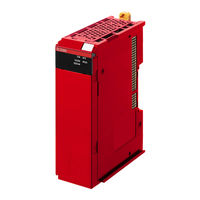
Omron NX-SL5500 User Manual (626 pages)
NX series safety control unit
Brand:
Omron
| Category:
Controller
| Size: 34.01 MB
Table of Contents
Introduction
3
Intended Audience
3
Applicable Products
3
Sections in this Manual
5
Table of Contents
6
Relevant Manuals
13
Manual Structure
15
Page Structure
15
Special Information
16
Precaution on Terminology
16
Terms and Conditions Agreement
17
Warranty, Limitations of Liability
17
Application Considerations
18
Disclaimers
18
Safety Precautions
20
Definition of Precautionary Information
20
Symbols
20
Warnings
21
Precautions for Safe Use
26
Precautions for Correct Use
31
Regulations and Standards
33
Conformance to EU Directives
33
Conformance to en ISO 13849-1 and en 62061
34
Conformance to UL and CSA Standards
35
Conformance to Shipbuilding Standards
35
Conformance to KC Certification
35
Unit Versions
37
Unit Versions of Units and Sysmac Studio Versions
38
Related Manuals
39
Terminology
41
Revision History
44
Overview
47
Section 1 Overview
48
Introduction and Features
48
Overview of Safety Control Unit
48
Features of Safety Control Unit
51
System Configuration and Configuration Devices
54
Safety Control System Configuration on NX Bus of CPU Unit or Ethercat Network
54
Safety Control System Configuration on Ethernet/Ip Network
56
Standalone Safety Control System Configuration
56
Types of Safety Control Unit
57
Support Software
58
Applicable Support Software
58
Connection Method and Procedures for Ethercat Coupler Units
58
Connection Method and Procedures for Ethernet/Ip Coupler Units
60
Commissioning Procedures
61
Overall Procedure
61
Detailed Procedures
62
Specifications
67
Section 2 Specifications
68
Safety CPU Unit
68
Models and Specifications
68
Part Names and Functions
74
Indicators
76
Safety Input Unit
82
Models and Specifications
82
Part Names and Functions
88
Indicators
90
Safety Output Unit
94
Models and Specifications
94
Part Names and Functions
101
Indicators
104
Pfh
107
Installation and Wiring
109
Section 3 Installation and Wiring
110
Installing Units
110
Installing NX Units
110
Attaching Markers
112
Removing Units
113
Installation Orientation
114
Power Supply Types and Wiring
116
Applications of I/O Power Supply and Supply Methods
116
Calculating the Total Current Consumption from I/O Power Supply
117
Wiring the Terminals
118
Wiring to the Screwless Clamping Terminal Blocks
118
Checking Wiring
131
Safety Control Unit Operation
133
Section 4 Safety Control Unit Operation
134
Relationship between Units and Types of Communications
134
Safety Control System on CPU Rack or Ethercat Network
134
Safety Control System on Ethernet/Ip Network
136
Standalone Safety Control System
138
I/O System
140
Relationship between the Types of Signals and the Types of Communications
140
Relationship between the Types of Signals and the Types of Com- Munications
140
Safety Data Types and Standard Data Types
140
Specifying Safety Data Types and Standard Data Types
141
Safety I/O Function
142
Safety Input Function
142
Safety Output Function
164
Section 5 System Configuration and Setup
174
System Configuration and Setup
174
Configuration and Setup Procedures
174
Part Names and Functions of the Sysmac Studio Window
175
Controller Configuration and Setup of the Safety Control Units
177
Procedures for Creating the Controller Configuration for Safety Control
178
Setting and Viewing the Safety Control Unit Settings
181
Procedure to Change the Model of the Safety Control Unit
182
Setting up the Safety Process Data Communications
184
Setting up the Fsoe Communications
184
Setting up the CIP Safety Communications
185
Calculating the Number of Connections
192
Safety I/O Functions
195
Registering Device Variables
198
Exposing Variables to Standard Controllers
202
Exposing Global Variables
202
Setting Exposed Variables
203
Safety CPU Unit Status
207
I/O Ports for Safety I/O Units
208
I/O Refreshing Method
208
Setting Standard Process Data Communications
209
Using an CPU Unit or Ethercat Coupler Unit
209
Using an Ethernet/Ip Coupler Unit
209
Exporting/Importing Settings Data
211
Exporting/Importing the Settings for the Entire Slave Terminal
211
Exporting/Importing the Settings for All the NX Units on a CPU Rack or Slave Terminal
213
Exporting/Importing Data for Individual Safety CPU Unit
214
Programming
217
Section 6 Programming
219
Pous (Program Organization Units)
219
Pou
219
Overview of the Three Types of Pous
219
Differences between Programs, Functions, and Function Blocks
220
Details on Programs
221
Details on Function Blocks
222
Details on Functions
226
Instructions
227
Variables
228
Types of Variables
228
Type of User-Defined Variable
228
Attributes of Variables
229
Data Type
230
Variable Attributes Other than Data Type
232
Function Block Instances
233
Restrictions on Variable Names and Other Safety Program-Related Names
233
Constants (Literals)
235
Constants
235
Types of Constants
235
Programming Languages
237
FBD Language
237
Programming Operations
242
Programming Layer on the Sysmac Studio
242
Registering Pous
243
Registering Variables
252
FBD Programming
257
Function Block Conversion for Programs
276
Building
277
Searching and Replacing
279
Safety Task Settings
282
Automatic Programming
284
Generation Algorithms for Automatic Programming
284
Automatic Programming Settings
287
Automatic Programming Execution Procedure
290
Monitoring Memory Usage for Safety Control Unit
293
Offline Debugging
295
Offline Safety Program Debugging
295
Monitoring
298
Controlling BOOL Variables, Changing Present Values, and Using Forced Refreshing
298
Setting the Initial Values of Variables
298
Feedback Settings
299
Simple Automatic Test
300
Checking Operation and Actual Operation
307
Section 7 Checking Operation and Actual Operation
309
Procedures before Operation and Transferring the Required Data
309
Commissioning Procedure
309
Data that You Must Transfer before Operation and Data Transfer Procedures
310
Transferring the Configuration Information
313
Overview
313
Transfer Procedure for a Connection to NJ/NX-Series CPU Unit
314
Transfer Procedure for a Connection to Communications Coupler Unit
314
Operating Modes of the Safety CPU Unit
317
Startup Operating Mode and Changing the Operating Mode
317
Operation When Changing Operating Mode
319
Executable Functions in each Mode of the Safety CPU Unit
320
Changing to DEBUG Mode
323
Checking External Device Wiring
326
Overview of Functions for Checking Wiring
326
Monitoring Safety I/O Units
326
Troubleshooting Safety I/O Terminals
330
Clear All Memory Operation for Safety I/O Units
331
Functions for Checking Operation
333
Overview of Functions for Checking Operation
333
Starting and Stopping the Safety Programs in DEBUG Mode
333
Monitoring Variables in the FBD Editor
333
Monitoring Variables in a Watch Tab Page
333
Controlling BOOL Variables, Changing Present Values, and Using Forced Refreshing
333
Monitoring Variables in the FBD Editor
334
Monitoring Variables in a Watch Tab Page
335
Controlling BOOL Variables, Changing Present Values, and Using Forced Refreshing
337
Online Functional Test
346
Online Functional Test Settings
346
Online Functional Test Execution Procedure
350
Node Name
356
Security Settings
357
Setting the Safety Password
357
Data Protection
358
Performing Safety Validation and Operation
362
Performing Safety Validation
362
Changing to RUN Mode
363
Changing to PROGRAM Mode
364
Uploading Configuration Information and Safety Application Data
366
Outline
366
Uploading Data for a Connection to an NJ/NX-Series CPU Unit
366
Uploading Data for a Connection to a Communications Coupler Unit
367
7-12 Transferring Safety Application Data
369
7-13 Monitoring Controller Status
370
7-14 Restarting and Clearing All Memory
372
Restarting
372
Clear All Memory Operation
373
Safety Reaction Time
380
Calculating the Safety Reaction Time
380
Verifying Safety Reaction Times
382
Safety Task
383
Operation of Safety Task
383
Minimum Safety Task Period
383
Setting the Safety Task Period
385
Fsoe Watchdog Timer
387
Fsoe Watchdog Timers
387
Checking Fsoe Watchdog Timers
387
Settings for Fsoe Watchdog Timers
388
Changing Fsoe Watchdog Timers
388
EPI (Data Packet Interval)
389
Changing the EPI
389
EPI Restrictions
389
Communications Load
391
Section 9 Communications Load
392
Adjusting the Communications Load
392
Checking Bandwidth Usage for Tag Data Links
393
Checking the Device Bandwidth Usage of the CIP Safety Routing
394
Relationship between the Number of Packets Used Per Second and Packet Intervals
395
Adjusting the Device Bandwidth Usage
395
Safety Unit Restore
397
Generate Safety Unit Restore File Function
398
10-1 Safety Unit Restore
398
Safety Unit Restore Function
399
Specifications of a Safety Unit Restore File
402
Safety Data Logging
403
Outline of the Safety Data Logging Function
404
Creating a Safety Data Logging Settings File with the Sysmac Studio
406
Safety Data Logging Operation Procedure
408
11-4 Checking the Logging Status
409
Checking the Seven-Segment Indicator
409
Checking with System-Defined Variables
409
11-5 Log File Specifications
410
Section 12 Troubleshooting
414
12-1 How to Check for Errors
414
Checking for Errors with the Indicators
415
Troubleshooting the Main Errors in the Safety CPU Unit
415
Troubleshooting the Main Errors in the Safety I/O Units
423
Checking for Errors with the Sysmac Studio
426
Checking for Errors from the Sysmac Studio
426
Types of Errors
427
Event Codes for Errors and Troubleshooting Procedures
429
Error Descriptions
443
12-4 Resetting Errors
502
Troubleshooting Flow When Errors Occur
503
Inspection and Maintenance
505
13-1 Cleaning and Inspection
506
Cleaning
506
Periodic Inspections
506
13-2 Maintenance Procedures
509
Replacing the Safety CPU Unit
509
Replacing Safety I/O Units
511
Appendices
515
A-1 Dimensions
515
A-1-1 Safety CPU Unit
515
Safety CPU Unit
515
A-1-2 Safety I/O Units
516
A-2 NX Objects
517
A-2-1 Format of NX Object Descriptions
517
A-2-2 Safety CPU Unit (NX-SL3300/NX-SL3500)
517
Format of NX Object Descriptions
517
Safety CPU Unit (NX-SL3300/NX-SL3500)
517
A-2-3 Safety CPU Unit (NX-SL5500/NX-SL5700)
519
Safety CPU Unit (NX-SL5500/NX-SL5700)
519
A-2-4 NX-SID800 Safety Input Unit
523
NX-SID800 Safety Input Unit
523
A-2-5 NX-SIH400 Safety Input Unit
528
NX-SIH400 Safety Input Unit
528
A-2-6 NX-SOD400 Safety Output Unit
533
NX-SOD400 Safety Output Unit
533
A-2-7 NX-SOH200 Safety Output Unit
537
NX-SOH200 Safety Output Unit
537
A-3 Application Examples
542
A-3-1 Emergency Stop Pushbutton Switches
542
Emergency Stop Pushbutton Switches
542
A-3-2 Safety Doors
544
A-3-3 Safety Laser Scanners
548
Safety Laser Scanners
548
A-3-4 Safety Door Switches with Magnetic Locks and Key Selector Switches
551
Safety Door Switches with Magnetic Locks and Key Selector Switches
551
A-3-5 Enable Switches
555
A-3-6 Two-Hand Switches
559
Two-Hand Switches
559
A-3-7 D40A Non-Contact Door Switches
562
D40A Non-Contact Door Switches
562
A-3-8 D40Z Non-Contact Door Switches
565
D40Z Non-Contact Door Switches
565
A-3-9 Safety Mats and Safety Light Curtains
568
Safety Mats and Safety Light Curtains
568
A-3-10 Safety Edges
573
Safety Edges
573
A-3-11 Single Beam Safety Sensor
575
A-3-12 Multi-Axis Servo Drives (STO)
578
A-4 Change Tracking
582
A-5 Safety CPU Unit Status
584
Nx-Sl3300/Nx-Sl3500
584
Nx-Sl5500/Nx-Sl5700
584
A-6 I/O Ports of Safety I/O Units
586
A-6-1 NX-SIH400 Safety Input Unit
586
NX-SIH400 Safety Input Unit
586
A-6-2 NX-SID800 Safety Input Unit
588
NX-SID800 Safety Input Unit
588
A-6-3 NX-SOH200 Safety Output Unit
589
NX-SOH200 Safety Output Unit
589
A-6-4 NX-SOD400 Safety Output Unit
590
NX-SOD400 Safety Output Unit
590
A-7 CIP Response Codes
593
A-7-1 General Status Codes
593
General Status Codes
593
Extended Status Codes
595
Icon List for Safety Slave Unit Parameters
598
External Device Icons for Input Devices
598
A-8-2 Contact Icons for Input Devices
601
Contact Icons for Input Devices
601
A-8-3 External Device Icons for Output Devices
603
External Device Icons for Output Devices
603
A-8-4 Contact Icons for Output Devices
604
Contact Icons for Output Devices
604
Calculating I/O Sizes for CPU Rack or Slave Terminals
605
A-10 Printing
606
A-10-1 Selecting the Items to Print
606
A-10-2 Items that Are Printed
606
List of Screwless Clamping Terminal Block Models
608
A-11-1 Model Notation
608
A-11-2 List of Terminal Block Models
608
I/O Response Times for Communications between NX Units on Ethernet/Ip Slave Terminals
610
Units that Support Communications between NX Units
612
Checking the Signature Code on the Seven-Segment Indicator
613
Execution Scenarios for the Simple Automatic Test
614
Differences in Checking Operation between the Simulator and Safety CPU Unit
616
A-17 Version Information
617
Relationship between Unit Versions and Sysmac Studio Versions
617
A-17-2 Functions that Were Added or Changed for each Version
621
Advertisement
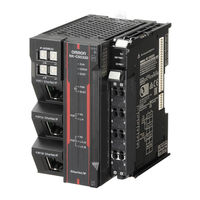
Omron NX-SL5500 Network Connection Manual (51 pages)
Machine Automation Controller, IO-Link Connection Guide
Brand:
Omron
| Category:
Controller
| Size: 3.62 MB
Table of Contents
Table of Contents
3
Related Manuals
4
Terms and Definitions
5
Precautions
6
Introduction
7
Target Devices and Device Configurations
9
Communication Related Settings
13
Mounting the IO-Link Master Unit
14
IO-Link Master Unit Communications Setup
16
Checking IO-Link Communications
25
Programming Using IO-Link
28
Initialization Method
48
Revision History
50
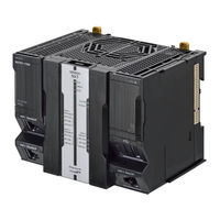
Omron NX-SL5500 Manual (24 pages)
Communication Control Unit/Safety Control Units
Brand:
Omron
| Category:
Control Unit
| Size: 4.66 MB
Table of Contents
Ordering Information
3
Optional Products
4
Regulations and Standards
5
General Specifications
5
Specifications of Individual Units
6
Function Specifications
12
Version Information
13
System Units
14
External Interface
15
Applicable Wires
19
Related Manuals
22
Advertisement
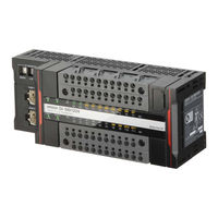
Omron NX-SL5500 How To Connect (17 pages)
CIP Safety IO block
Brand:
Omron
| Category:
I/O Systems
| Size: 1.01 MB
Table of Contents
Table of Contents
2
1 Application Devices and Device Configuration
3
Applicable Devices
3
Device Configuration
4
2 Ethernet/Ip Safety Connection Procedure
5
Safety Controller Setup
5
Hardware Configuration and IP Address Settings
5
Starting Sysmac Studio and Going Online
6
Creating a Safety Controller Unit Configuration
7
Network Setting with Sysmac Studio
8
Setting the Connections
8
Transferring Program with Sysmac Studio
13
Setting Global Variables
13
Transferring the Safety Application Data
14
Transferring the Safety Program
15
3 Acknowledgement
17
Advertisement
Related Products
Omron NX-SL3300
Omron NX-SL3500
Omron NX-SL5700
Omron NX Series
Omron NX-SOH200
Omron NX-SOH400
Omron NX-SIH400
Omron NX-SID Series
Omron NX-SOH
Omron NX-SID800
Omron Categories
Blood Pressure Monitor
Controller
Accessories
Switch
Inverter
More Omron Manuals
Login
Sign In
OR
Sign in with Facebook
Sign in with Google
Upload manual
Upload from disk
Upload from URL