
Related Manuals for Omron W4S1-0 Series


Summary of Contents for Omron W4S1-0 Series
- Page 1 Rev. 1.1 How to connect Omron NX-CSG320 + NX-SL5500 With Omron GI-SMDxxxx CIP Safety IO block...
-
Page 2: Table Of Contents
Rev. 1.1 Table of Contents Application Devices and Device Configuration ..................1 1.1. Applicable Devices ........................1 1.2. Device Configuration ........................2 EtherNet/IP Safety Connection Procedure ................... 3 2.1. Safety Controller Setup ......................... 3 2.1.1. Hardware configuration and IP address Settings ..............3 2.1.2. -
Page 3: Application Devices And Device Configuration
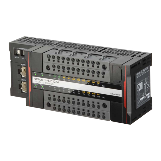
1. Application Devices and Device Configuration 1.1. Applicable Devices The applicable devices are as follows: Manufacturer Name Model OMRON Ethernet switch W4S1-0xx OMRON NX-series Safety CPU unit NX-SL5xxx OMRON NX-series Communication Control unit NX-CSGxxxx OMRON Omron Safety I/O block GI-SMD1624... -
Page 4: Device Configuration
Rev. 1.0 1.2. Device Configuration GI-SMD1624 Manufacturer Name Model Version OMRON Ethernet switch W4S1-05B OMRON NX-series Safety CPU unit NX-SL5500 Ver. 1.3 OMRON NX-series Communication Control NX-CSG3200 Ver. 1.01 unit OMRON Sysmac Studio SYSMAC-SE2xxx Ver.1.25.1 OMRON Compress CIP device file CIP_Safety_XXXXX.zip... -
Page 5: Ethernet/Ip Safety Connection Procedure
Rev. 1.0 2. EtherNet/IP Safety Connection Procedure This section describes the procedures for connecting the Omron safety I/O block and the safety controller via EtherNet/IP safety. 2.1. Safety Controller Setup Set up the Safety Controller. The Sysmac Studio is used for the Safety Controller setup, please install before proceeding. -
Page 6: Starting Sysmac Studio And Going Online
Rev. 1.0 2.1.2. Starting Sysmac Studio and Going Online Start Sysmac Studio and go online with the Safety Controller. Power up the Safety Controller and the I/O block Launch Sysmac Studio Form Sysmac Studio start page select Connect to Device From the connect to device page: •... -
Page 7: Creating A Safety Controller Unit Configuration
Rev. 1.0 2.1.3. Creating a Safety Controller Unit Configuration Create and setup a unit configuration for the Safety Controller. Hardware configuration. • From the Multiviewer Explorer select Configurations and Setup -> CPU/Expansion Racks • Double click CPU Rack • From the CPU/Expansion Racks tab right click on Unit 0 (NX-CSG320). -
Page 8: Network Setting With Sysmac Studio
Set the EtherNet/IP safety connection. 2.2.1. Setting the Connections Set connection between the Safety Controller and the Omron Safety I/O Block. In the connection setting via the built-in EtherNet/IP port 2 of the Safety Controller, configure the I/O block to use as a target device. - Page 9 Rev. 1.0 The Connection Settings (Originator) tab page is displayed. Click on to the right of Safety Network Number for EtherNet/IP Port 1 to edit. The Safety Network Number Settings dialog box is display. The safety network number (SNN) default setting is Auto, if not, select Auto to generate the SNN for the EtherNet/IP Port 1.
- Page 10 Rev. 1.0 Set the GI nodes IP address Note: Use clear memory function if below does not seem to work. Changing IP address is sometimes not allowed if TUNID is set. Z400 section 6-4-3 Mode 0: 192.168.250.x x set by x16 and x1 Mode 4: DHCP see manual Z400 To program the GI...
- Page 11 Rev. 1.0 To program each input select I/O Configuration tab -> Input. To program each output select I/O Configuration tab -> Output. Transfer program to Safety PLC (see section 2.4) Transfer setting to NX- CSG320 or NX102...
- Page 12 Rev. 1.0 Set GI TUNID Z400 section 6-4-2...
-
Page 13: Transferring Program With Sysmac Studio
Rev. 1.0 2.3. Transferring Program with Sysmac Studio Transfer the Safety Network Controller and the Safety CPU program. 2.3.1. Setting Global Variables Set global variables for the Safety Controller Click Go To I/O Map in the Connection Settings (Originator) Tab page. In the I/O Map click to expand. -
Page 14: Transferring The Safety Application Data
Rev. 1.0 2.3.2. Transferring the Safety Application Data Transfer the safety application data to the Safety Network Controller (NX-CSGxxx) From the Multiview Explorer, select new_Controller_0 From Project -> Build Controller to check for errors and compile the project From Controller -> Online to go online to the safety network controller From Controller ->... -
Page 15: Transferring The Safety Program
Rev. 1.0 2.3.3. Transferring the Safety Program Transfer the safety program to the safety CPU unit. From the Multiview Explorer, select new_SafetyCPU0. In the Offline mode create the safety program. Select from the top menu Project -> Build Controller to check for errors and compile the project. - Page 16 Rev. 1.0 Select from the top menu Controller -> Mode -> Safety Validation to validate the safety program. The Create boot application dialog box is displayed. Select Yes. The information dialog box is displayed. Select OK. The Safety Validation dialog box is displayed.
-
Page 17: Acknowledgement
Rev. 1.0 3. Acknowledgement • EtherNet/IP is a trademark of ODVA, INC.
Need help?
Do you have a question about the W4S1-0 Series and is the answer not in the manual?
Questions and answers