Omron NX Series User Manual
Machine automation controller
Hide thumbs
Also See for NX Series:
- User manual (326 pages) ,
- Hardware user manual (222 pages) ,
- Reference manual (116 pages)

Related Manuals for Omron NX Series


Summary of Contents for Omron NX Series
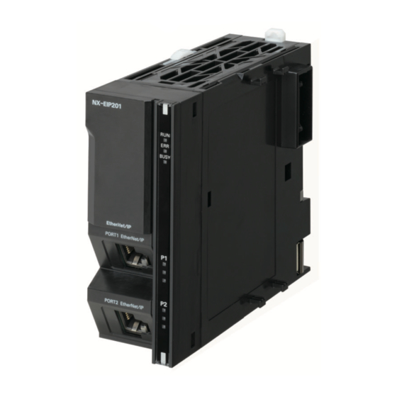
- Page 1 Machine Automation Controller NX-series EtherNet/IP Unit User’s Manual NX-EIP201 EtherNet/IP Unit W627-E1-01...
- Page 2 Moreover, because OMRON is constantly striving to improve its high-quality products, the infor- mation contained in this manual is subject to change without notice. 3. Every precaution has been taken in the preparation of this manual. Nevertheless, OMRON as- sumes no responsibility for errors or omissions.
-
Page 3: Intended Audience
Introduction Introduction Thank you for purchasing an NX-series EtherNet/IP Unit. This manual contains information that is necessary to use the NX-series EtherNet/IP Unit. Please read this manual and make sure you understand the functionality and performance of the NX-series Ether- Net/IP Unit before you attempt to use it in a control system. -
Page 4: Relevant Manuals
Relevant Manuals Relevant Manuals The following table provides the relevant manuals for the NX-series CPU Units. Read all of the man- uals that are relevant to your system configuration and application before you use the NX-series CPU Unit. Most operations are performed from the Sysmac Studio Automation Software. Refer to the Sysmac Studio Version 1 Operation Manual (Cat. - Page 5 Relevant Manuals Manual Basic informa- tion Purpose of use Testing operation and debugging Using motion control Using EtherCAT Using EtherNet/IP Using OPC UA Using FINS Using the database connection service Learning about error management and cor- rections Maintenance Using motion control Using EtherCAT Using EtherNet/IP Refer to the NJ/NX-series Troubleshooting Manual (Cat.
-
Page 6: Manual Structure
Manual Structure Manual Structure Page Structure The following page structure is used in this manual. Level 1 heading 4 Installation and Wiring Level 2 heading Mounting Units Level 3 heading Level 2 heading Gives the current Level 3 heading headings. 4-3-1 Connecting Controller Components The Units that make up an NJ-series Controller can be connected simply by pressing the Units together... -
Page 7: Special Information
Manual Structure Special Information Special information in this manual is classified as follows: Precautions for Safe Use Precautions on what to do and what not to do to ensure safe usage of the product. Precautions for Correct Use Precautions on what to do and what not to do to ensure proper operation and performance. Additional Information Additional information to read as required. - Page 8 Manual Structure NX-series EtherNet/IP Unit User's Manual (W627)
-
Page 9: Sections In This Manual
Sections in this Manual Sections in this Manual Features and CIP Message System Configuration Communications Specifications and SNMP Agent Application Procedures Communications Per- Part Names and formance and Commu- Functions nications Load Instructions Specific to Mounting NX-series EtherNet/IP Units Installing Ethernet Troubleshooting Networks Device Variables... -
Page 10: Table Of Contents
CONTENTS CONTENTS Introduction ......................1 Intended Audience............................1 Applicable Products ............................1 Relevant Manuals..................... 2 Manual Structure...................... 4 Page Structure..............................4 Special Information ............................5 Precaution on Terminology ..........................5 Sections in this Manual ................... 7 Terms and Conditions Agreement................ 14 Warranty, Limitations of Liability ........................14 Application Considerations ..........................15 Disclaimers ..............................15 Statement of security responsibilities for assumed use cases and against threats........16... - Page 11 CONTENTS Section 2 Specifications and Application Procedures Specifications.........................2-2 2-1-1 General Specifications ........................2-2 2-1-2 Performance Specifications ......................2-3 2-1-3 Function Specifications .......................2-5 EtherNet/IP Communications Procedures................2-6 Section 3 Part Names and Functions Part Names ..........................3-2 Part Functions........................3-3 3-2-1 Operation Status Indicators......................3-3 3-2-2 DIP Switch...........................3-4 Section 4 Mounting Mounting and Removing NX-series EtherNet/IP Units ............4-2...
- Page 12 CONTENTS SNMP Trap Settings Display ....................7-13 CIP Settings Display ......................7-15 Section 8 TCP/IP Functions Determining IP Addresses ....................8-2 8-1-1 IP Addresses ..........................8-2 8-1-2 EtherNet/IP Port IP Address Settings ..................8-4 8-1-3 Private and Global Addresses.....................8-9 Default States of TCP/UDP Ports and the Changing Procedure ........8-12 Testing Communications ....................8-13 8-3-1 PING Command ........................8-13...
- Page 13 CONTENTS Tag Data Links with Other Models ..................9-78 QuickConnect........................9-82 9-5-1 Method of Use ...........................9-82 9-5-2 Managed Switches ........................9-83 Section 10 CIP Message Communications 10-1 Overview of the CIP Message Communications Service ..........10-2 10-1-1 Overview of the CIP Message Communications Service ............10-2 10-1-2 Message Communications Service Specifications..............10-2 10-2 Client Function of CIP Message Communications ............10-3...
- Page 14 CONTENTS 12-3 Tag Data Link I/O Response Time ..................12-23 12-3-1 Timing of Data Transmissions ....................12-23 12-3-2 Maximum Tag Data Link I/O Response Time................12-23 12-4 Message Service Transmission Delay ................12-27 Section 13 Instructions Specific to NX-series EtherNet/IP Units Commonly Used Structure Variables ...................13-2 TDLinkStartConnection .........................13-3 Variables ..............................13-3 Related Device Variables..........................13-4...
- Page 15 CONTENTS A-3-5 Checking Communications Status with the Sysmac Studio and Troubleshooting ....A-32 A-3-6 Troubleshooting........................A-37 EDS File Management ......................A-43 A-4-1 Installing EDS Files ........................A-43 A-4-2 Creating EDS Files........................A-44 A-4-3 Deleting EDS Files ........................A-44 A-4-4 Saving EDS Files ........................A-45 A-4-5 Searching EDS Files ........................
-
Page 16: Terms And Conditions Agreement
Omron’s exclusive warranty is that the Products will be free from defects in materials and work- manship for a period of twelve months from the date of sale by Omron (or such other period ex- pressed in writing by Omron). Omron disclaims all other warranties, express or implied. -
Page 17: Application Considerations
WAY CONNECTED WITH THE PRODUCTS, WHETHER SUCH CLAIM IS BASED IN CONTRACT, WARRANTY, NEGLIGENCE OR STRICT LIABILITY. Further, in no event shall liability of Omron Companies exceed the individual price of the Product on which liability is asserted. Application Considerations... -
Page 18: Statement Of Security Responsibilities For Assumed Use Cases And Against Threats
Product. Errors and Omissions Information presented by Omron Companies has been checked and is believed to be accurate; how- ever, no responsibility is assumed for clerical, typographical or proofreading errors or omissions. Statement of security responsibilities for assumed use cases and... -
Page 19: Safety Precautions
Safety Precautions Safety Precautions Definition of Precautionary Information The following notation is used in this manual to provide precautions required to ensure safe usage of the NX-series X Bus Unit. The safety precautions that are provided are extremely important for safety. Always read and heed the information provided in all safety precautions. -
Page 20: Warnings
Safety Precautions Warnings WARNING During Power Supply Do not attempt to take any Unit apart. In particular, high-voltage parts are present in the Power Supply Unit while power is supplied or immediately after power is turned OFF. Touching any of these parts may result in electric shock. - Page 21 Safety Precautions Security measures to prevent unauthorized access Take the following measures to prevent unauthorized access to our products. • Install physical controls so that only authorized personnel can access control sys- tems and equipment. • Reduce connections to control systems and equipment via networks to prevent ac- cess from untrusted devices.
-
Page 22: Precautions For Safe Use
Precautions for Safe Use Precautions for Safe Use Transporting and Disassembly • Do not attempt to disassemble, repair, or modify any Units. Doing so may result in malfunction or fire. • Do not drop any Unit or subject it to abnormal vibration or shock. Doing so may result in Unit mal- function or burning. - Page 23 Precautions for Safe Use EtherNet/IP Unit are being backed up in the built-in non-volatile memory. This data will not be backed up correctly if the power supply is turned OFF. Also, a minor fault level Controller error will occur the next time you start operation, and the NX-series EtherNet/IP Unit will stop the operation. •...
- Page 24 Precautions for Safe Use Unit Replacement • Make sure to transfer the tag data link settings and routing tables before restarting operation after you replaced the NX-series EtherNet/IP Unit. NX-series EtherNet/IP Unit User's Manual (W627)
-
Page 25: Precautions For Correct Use
Precautions for Correct Use Precautions for Correct Use Storage and Installation • Follow the instructions in this manual to correctly perform installation. • Do not operate or store the Controller in the following locations. Doing so may result in burning, in operation stopping, or in malfunction. - Page 26 It is recommended that you erase the data on your responsibility before disposing of or transferring the device. Omron shall not be liable for any loss, damage, or other expenses incurred directly or indirectly in the event of any information leakage due to disposal or transfer.
-
Page 27: Regulations And Standards
Regulations and Standards Regulations and Standards Refer to the following manuals for regulations and standards. • NX-series NX502 CPU Unit Hardware User’s Manual (Cat. No. W629) NX-series EtherNet/IP Unit User's Manual (W627) -
Page 28: Unit Versions
Shows the lot number and the serial number of the Unit. number DDMYY: Lot number, £: For use by OMRON, SSSS: Serial number M is 1 to 9 for January to September, X for October, Y for November, and Z for De- cember. -
Page 29: Related Manuals
Related Manuals Related Manuals The following manuals are related. Use these manuals for reference. Manual name Cat.No. Model numbers Application Description NX-series W627 NX-EIP201 Learning how to use Information on the NX-series Ether- the NX-series Ether- Net/IP Unit is provided. ™... - Page 30 Related Manuals Manual name Cat.No. Model numbers Application Description NJ/NX-series W506 NX701-££££ Using the built-in Information on the built-in CPU Unit NX502-££££ EtherNet/IP port on EtherNet/IP port is provided. NX102-££££ an NJ/NX-series Information is provided on the basic ™ Built-in EtherNet/IP Port NX1P2-££££...
-
Page 31: Revision History
Revision History Revision History A manual revision code appears as a suffix to the catalog number on the front and back covers of the manual. W627-E1-01 Cat. No. Revision code Revision Date Revised content code April 2023 Original production NX-series EtherNet/IP Unit User's Manual (W627) - Page 32 Revision History NX-series EtherNet/IP Unit User's Manual (W627)
-
Page 33: Features And System Configuration
Features and System Configura- tion This section describes the features, system configuration, introduction to communica- tions services, and Support Software of the NX-series EtherNet/IP Unit. Features ......................1-2 1-1-1 EtherNet/IP Features..................1-2 1-1-2 Features of NX-series EtherNet/IP Units............1-2 System Configuration ..................1-6 Introduction to Communications Services .......... -
Page 34: Features
1 Features and System Configuration Features The NX-series EtherNet/IP Unit has the EtherNet/IP function when mounted on the X Bus. The EtherNet/IP and NX-series EtherNet/IP Unit have the following features. 1-1-1 EtherNet/IP Features EtherNet/IP is an industrial multi-vendor network that uses Ethernet. The EtherNet/IP specifications are open standards managed by the ODVA (Open DeviceNet Vendor Association), just like DeviceNet. - Page 35 1 Features and System Configuration l X Bus Connection which Enable High-speed and Large Capacity Data Transfer The NX502 CPU Unit has a built-in X Bus, which is an internal bus capable of transferring data at higher speed and larger capacity than the NX bus. The NX-series EtherNet/IP Unit is one of the X Bus Units that are connected to the X Bus.
- Page 36 1 Features and System Configuration Additional Information CIP (Common Industrial Protocol) CIP is a shared industrial protocol for the OSI application layer. The CIP is used in networks such as EtherNet/IP, CompoNet, and DeviceNet. Data can be routed easily between networks that are based on the CIP. You can therefore easi- ly configure a transparent network from the field device level to the host level.
- Page 37 1 Features and System Configuration l CIP Safety on EtherNet/IP Compatible Combined with the NX-SL5£££ Safety Control Unit, you can build a system which uses CIP Safety on EtherNet/IP communications in networks between Controllers and field networks. Safety communications by CIP Safety is enabled with devices that support CIP Safety on EtherNet/IP and other Safety CPU Units.
-
Page 38: System Configuration
1 Features and System Configuration System Configuration The following figure shows a configuration example for a system that uses the NX-series EtherNet/IP Unit. Process Controller Machine Controller Sysmac Studio Sysmac Studio Network Configurator Network Configurator HOST PC NX-series Ethernet Ethernet NX502 CPU Unit Switch Switch... - Page 39 1 Features and System Configuration NX502 CPU Unit Configura- Description connection meth- tion element FSoE I/O This Unit inputs safety input signals and out- NX bus of CPU Unit Zero to multiple Units Unit puts safety output signals in combination with a and Slave Terminal (depends on applica- Safety CPU Unit.
-
Page 40: Introduction To Communications Services
1 Features and System Configuration Introduction to Communications Services This section provides an introduction to the communications services of the NX-series EtherNet/IP Unit. 1-3-1 CIP (Common Industrial Protocol) Communications Services The services using CIP include tag data link and CIP message communications. Tag Data Links (Cyclic Communications) A program is not required to perform cyclic data exchanges with other devices on the EtherNet/IP net- work. - Page 41 1 Features and System Configuration Note In this example, a connection is established with the originator’s tag list with tags a to g (inputs), which are in a tag set called SP1_IN, and the target’s tag list with tags i and ii (outputs), which are in a tag set called SP1_OUT.
-
Page 42: Ip Routing
In the case of relay hops, the timeout for the relay route must be added to the timeout for the request. OMRON products that support CIP subtract 5 seconds per hop. 1-3-2 IP Routing The IP routing function sends IP packets to other network segments based on the routing information set in the IP router table. -
Page 43: Packet Filter
1 Features and System Configuration Additional Information CIP routing is not affected by the IP Forward setting. 1-3-3 Packet Filter IP packets are filtered in the receive processing at the EtherNet/IP ports. Specify packets allowed to be received by IP address or TCP/UDP port number. 1-3-4 BOOTP Client You set the EtherNet/IP port to the BOOTP setting to use the BOOTP client to obtain settings, such as... -
Page 44: Snmp Agent
1 Features and System Configuration 1-3-6 SNMP Agent The SNMP agent has the following functions. SNMP Agent EtherNet/IP port internal status information is provided to network management software that uses an SNMP manager. Monitors devices on Ethernet/IP SNMP manager EtherNet/IP port Ethernet SNMP message Management... -
Page 45: Lldp
1 Features and System Configuration 1-3-7 LLDP LLDP (Link Layer Discovery Protocol) is a protocol used to exchange information with other network devices that are connected to a physically communicable range. The NX-series EtherNet/IP Unit ob- tains information of other network devices using the SNMP function. The information to be exchanged includes chassis types and system names of the both. -
Page 46: Support Software
1 Features and System Configuration Support Software The followings are the Support Software for using the NX-series EtherNet/IP Unit. l Sysmac Studio This software is used to configure all functions of the NX-series EtherNet/IP Unit. The NX-series EtherNet/IP Unit is supported by version 1.54 or higher. Refer to the Sysmac Studio Version 1 Operation Manual (Cat. - Page 47 Specifications and Application Procedures This section describes the specifications and application procedures of the NX-series EtherNet/IP Unit. Specifications ....................2-2 2-1-1 General Specifications ..................2-2 2-1-2 Performance Specifications................2-3 2-1-3 Function Specifications ................... 2-5 EtherNet/IP Communications Procedures ........... 2-6 NX-series EtherNet/IP Unit User's Manual (W627)
-
Page 48: Specifications
Gravity acceleration is assumed to be G=9.8m/s Mounting method Mount to DIN Track Mounting direction One direction (upright) Applicable standards Refer to the OMRON website (http:// www.ia.omron.com/) or consult your OMRON represen- tative for the applicable standards. NX-series EtherNet/IP Unit User's Manual (W627) -
Page 49: Performance Specifications
2 Specifications and Application Procedures 2-1-2 Performance Specifications The specifications of the NX-series EtherNet/IP Unit are given below. NX-EIP201 Item Ether- Number of ports Net/IP Physical layer 10BASE-T, 100BASE-TX, or port 1000BASE-T Frame length 1,514 bytes max. Media access method CSMA/CD Modulation Baseband... - Page 50 2 Specifications and Application Procedures NX-EIP201 Item CIP message Class 3 (number of connections) 128 per port service: Explic- 256 total it messages (clients plus server) UCMM (non-connec- Maximum number of 32 per port tion type) clients that can com- 64 total municate at one time Maximum number of...
-
Page 51: Function Specifications
2 Specifications and Application Procedures 2-1-3 Function Specifications The function specifications of the NX-series EtherNet/IP Unit are given below. Item NX-EIP201 Communica- EtherNet/I Communications protocol TCP/IP or UDP/IP tions P port CIP communications Tag data links Programless cyclic data exchange services is performed with the devices on the EtherNet/IP network. -
Page 52: Ethernet/Ip Communications Procedures
2 Specifications and Application Procedures EtherNet/IP Communications Proce- dures l Basic Operation Wire the Ethernet network with twisted-pair cable. Section 5 Installing Ethernet Net- works on page 5-1 ↓ Set the EtherNet/IP port IP address with the Sysmac Studio. 8-1 Determining IP Addresses on page 8-2 1. - Page 53 2 Specifications and Application Procedures • Check the EtherNet/IP port indicators. • Use the Sysmac Studio to check the communications status with the All Tag Data Link Communications Status device var- iable. • Use the monitor function of the Network Configurator to con- firm that the tag data links are in normal operation.
- Page 54 2 Specifications and Application Procedures NX-series EtherNet/IP Unit User's Manual (W627)
- Page 55 Part Names and Functions This section describes part names and functions of the NX-series EtherNet/IP Unit. Part Names ..................... 3-2 Part Functions ....................3-3 3-2-1 Operation Status Indicators................3-3 3-2-2 DIP Switch....................... 3-4 NX-series EtherNet/IP Unit User's Manual (W627)
-
Page 56: Part Names
3 Part Names and Functions Part Names The following table gives the name of each part of the NX-series EtherNet/IP Unit. (D) (A) Symbol Name Function X Bus connectors These connectors are used to connect another Unit. DIN Track mounting hook This hook is used to mount the Unit to a DIN Track. -
Page 57: Part Functions
3 Part Names and Functions Part Functions 3-2-1 Operation Status Indicators The operation status indicators include the Unit status indicators which display the operating status of the NX-series EtherNet/IP Unit and the EtherNet/IP (Port 1/Port 2) status indicators which display the status of EtherNet/IP ports. -
Page 58: Dip Switch
3 Part Names and Functions Indicator Color Indicator status Status of EtherNet/IP port NET ERR An error for which the user cannot recover operation occurred. Flashing An error for which the user can recover operation occurred. Not lit There are no Ethernet communications errors. •... - Page 59 Mounting This section describes how to mount the NX-series EtherNet/IP Unit. Mounting and Removing NX-series EtherNet/IP Units ....... 4-2 NX-series EtherNet/IP Unit User's Manual (W627)
-
Page 60: Mounting And Removing Nx-Series Ethernet/Ip Units
4 Mounting Mounting and Removing NX-series EtherNet/IP Units Refer to Mounting and Removing Units in the NX-series NX502 CPU Unit Hardware User’s Manual (Cat. No. W629) for how to mount and remove the NX-series EtherNet/IP Unit. NX-series EtherNet/IP Unit User's Manual (W627) -
Page 61: Installing Ethernet Networks
Installing Ethernet Networks Selecting the Network Devices ..............5-2 5-1-1 Recommended Network Devices ..............5-2 5-1-2 Ethernet Switch Types..................5-3 5-1-3 Ethernet Switch Functions................5-3 5-1-4 Precautions for Ethernet Switch Selection ............5-4 Network Installation ..................5-7 5-2-1 Basic Installation Precautions ................. 5-7 5-2-2 Recommended Network Devices .............. -
Page 62: Selecting The Network Devices
The following table shows the devices recommended for use with the EtherNet/IP. l Ethernet Switches Manufacturer Model Description OMRON W4S1-05D Packet priority control (QoS): EtherNet/IP control data priority Ethernet standard: IEEE 802.3 10Base-T, 100Base-TX Auto-negotiation: Supported Broadcast storm control: Supported... -
Page 63: Ethernet Switch Types
“Specific nodes” are nodes equipped with an IGMP client, and have made transfer requests to the Ethernet switch. (OMRON EtherNet/IP ports are equipped with an IGMP client.) When the Ethernet switch does not use multicast filtering, multicast packets are sent to all nodes, just like broadcast packets, which increases the traffic in the network. -
Page 64: Precautions For Ethernet Switch Selection
Managed L2 Ethernet switch Supported Supported Both functions must be set with a special software tool. OMRON Ethernet switch Not supported Supported L4 QoS is set with a switch. (W4S1-series Ethernet switches) No software tool is necessa- Even QoS settings are made, tag data links and CIP Safety communications are processed with the same priority. - Page 65 5 Installing Ethernet Networks If you set tag data links for higher-priority transmission, it is possible to prevent problems such as transmission delays due to message communications traffic and packet losses due to buffer over- flow. Refer to 7-5 CIP Settings Display on page 7-15 for details on the QoS settings. When multicast filtering and L4 QoS are used, settings must be made accordingly on the Ethernet switch.
- Page 66 5 Installing Ethernet Networks Selecting the Ethernet Switch Based on the Network Communica- tion Speed l Executing Tag Data Links at a Baud Rate Over 100 Mbps If you use data tag links with the following conditions, use an Ethernet switch with multicast filtering or an Ethernet switch that supports a baud rate of 1,000 Mbps.
-
Page 67: Network Installation
5 Installing Ethernet Networks Network Installation 5-2-1 Basic Installation Precautions • Take the greatest care when you install the Ethernet System. Be sure to follow ISO 8802-3 specifi- cations. Be sure you understand them before attempting to install an Ethernet System. •... - Page 68 5 Installing Ethernet Networks Connect the cable shields to the connector hoods as described in either (1) or (2) below. 1. Connecting the shields at both ends of the cable Connect the shields to the connector hoods at both ends of the cables. Ethernet switch Connect shield to connector hood Connector...
- Page 69 5 Installing Ethernet Networks Ethernet switch Connect shield to connector hood Do not connect shield to connector hood Connector Connector Connector terminal NX-series CPU Unit EtherNet/IP Unit EtherNet/IP port Clamp core Connector (Shield) NX-series CPU Unit EtherNet/IP Unit EtherNet/IP port Connector (Shield) Additional Information...
- Page 70 5 Installing Ethernet Networks Ethernet switch Connect shield to connector hood Connector Connector Connector NX-series terminal CPU Unit EtherNet/IP Unit EtherNet/IP port Connector (Shield) NX-series CPU Unit EtherNet/IP Unit EtherNet/IP port Connector (Shield) l Between Two Ethernet Switches Regardless of which baud rate is used, check with the Ethernet switch manufacturers for informa- tion about installing the network between Ethernet switches, and in particular whether or not it is necessary to connect the cable shields to the connector hoods.
-
Page 71: Precautions When Installing And Connecting Ethernet Switches
5 Installing Ethernet Networks 13 dia. max. 31.5 38.0 l Recommended Attachment Method • Attach a clamp core to the communications cable as shown below. Make two loops with the cable as shown. • Connect the communications cable as shown below. EtherNet/IP Attach close to the cable port... - Page 72 5 Installing Ethernet Networks MDI ports : Straight cable MDI-X port (cross) Ethernet switch : Cross cable Ethernet Ethernet Ethernet switch switch switch POWER POWER POWER POWER POWER POWER POWER POWER PORT2 PORT2 PORT2 PORT2 PORT2 PORT2 PORT2 PORT2 • Some Ethernet switches can automatically distinguish between MDI and MDI-X. When this kind of Ethernet switch is used, straight cable can be used between Ethernet switches.
-
Page 73: Connecting To The Network
5 Installing Ethernet Networks Connecting to the Network 5-3-1 Ethernet Connectors The following standards and specifications apply to the connectors for the Ethernet twisted-pair cable. • Electrical specifications: Conforming to IEEE 802.3 standards. • Connector structure: RJ45 8-pin Modular Connector (conforming to ISO 8877) •... - Page 74 5 Installing Ethernet Networks Connect the cable to the Ethernet switch. Connect the twisted-pair cable to the connector on the EtherNet/IP port. Be sure to press the connectors (both the Ethernet switch side and Ethernet side) until they lock into place. 5-14 NX-series EtherNet/IP Unit User's Manual (W627)
-
Page 75: Device Variables Related To The Nx-Series Ethernet/Ip Unit
Device Variables Related to the NX-series EtherNet/IP Unit What You Can Check with Device Variables..........6-2 6-1-1 Checking for Errors in the NX-series EtherNet/IP Unit........6-2 6-1-2 Checking for Status of the NX-series EtherNet/IP Unit ........6-4 Device Variables ..................... 6-5 Specifications for Individual Device Variables .......... - Page 76 6 Device Variables Related to the NX-series EtherNet/IP Unit What You Can Check with Device Var- iables You can use the device variables that are provided for the NX-series EtherNet/IP Unit in the user pro- gram to check errors that occur in the NX-series EtherNet/IP Unit and the status of the NX-series EtherNet/IP Unit.
- Page 77 6 Device Variables Related to the NX-series EtherNet/IP Unit Level 1 Level 2 Level 3 Level 4 Variable Name Variable Name Variable Name Variable Name _ErrSta Controller Er- _PLC_ErrSta PLC Func- The rest of levels are omit- ror Status tion Module ted.
-
Page 78: Checking For Status Of The Nx-Series Ethernet/Ip Unit
6 Device Variables Related to the NX-series EtherNet/IP Unit Level 5 Level 6 Level 7 Variable Name Variable Name Variable Name EIP_ErrSta CIP Com- EIP_Comm CIP Com- EIP_Comm1Status.Iden- CIP Communications1 Identity Error munica- 1Status.Ci- munica- tityErr tions Error pErr tions1 Error EIP_Comm1Sta- CIP Communications1 Tag Data Link tus.TDLinkCfgErr... -
Page 79: Device Variables
6 Device Variables Related to the NX-series EtherNet/IP Unit Device Variables The variables are described in the tables as shown below. Range of Variable name Meaning Function Data type Reference values This is the device This is the mean- The function of the variable is descri- The data The range The page of... - Page 80 6 Device Variables Related to the NX-series EtherNet/IP Unit Range of Variable name Meaning Function Data type Reference values ETN_Port2Sta- Communications This is the error status variable for the WORD 16#0000 to page 6-17 tus.PortErr Port2 Error communications port 2. 16#00F0 Represents the collective status of the following error flags.
- Page 81 6 Device Variables Related to the NX-series EtherNet/IP Unit Range of Variable name Meaning Function Data type Reference values ETN_Port1Sta- Port1 IP Address Indicates the IP address setting errors for BOOL TRUE or page 6-19 tus.IPAdrCfgErr Setting Error the communications port 1. FALSE TRUE: •...
- Page 82 6 Device Variables Related to the NX-series EtherNet/IP Unit Range of Variable name Meaning Function Data type Reference values EIP_ErrSta CIP Communications This is the error status variable for CIP WORD 16#0000 to page 6-21 Error communications. 16#00F0 Represents the collective status of the following error flags.
- Page 83 6 Device Variables Related to the NX-series EtherNet/IP Unit Range of Variable name Meaning Function Data type Reference values EIP_Comm2Sta- CIP Communica- Indicates that the identity information for BOOL TRUE or page 6-22 tus.IdentityErr tions2 Identity Error CIP communications 2 (which you cannot FALSE overwrite) is incorrect.
- Page 84 6 Device Variables Related to the NX-series EtherNet/IP Unit Range of Variable name Meaning Function Data type Reference values EIP_Comm1Sta- CIP Communica- Indicates that the tag resolution for CIP BOOL TRUE or page 6-23 tus.TagAdrErr tions1 Tag Name communications 1 failed (i.e., the ad- FALSE Resolution Error dress could not be identified from the tag...
- Page 85 6 Device Variables Related to the NX-series EtherNet/IP Unit Description 15 to 6 Reserved. This bit indicates whether a minor fault level Controller error has occurred. TRUE: A minor fault level Controller error has occurred. FALSE: A minor fault level Controller error has not occurred. This bit indicates whether an observation level Controller error has occurred.
- Page 86 6 Device Variables Related to the NX-series EtherNet/IP Unit Range of Variable name Meaning Function Data type Reference values EIP_Comm1Sta- CIP Communica- Gives a list of nodes for which ARRAY TRUE or page 6-25 tus.RegTarget- tions1 Registered EtherNet/IP connections are registered [0..255] OF FALSE Sta[255]...
- Page 87 6 Device Variables Related to the NX-series EtherNet/IP Unit Range of Variable name Meaning Function Data type Reference values EIP_Comm2Sta- CIP Communica- Shows the operating status of the target ARRAY TRUE or page 6-27 tus.TargetPLCMo- tions2 Target PLC node Controllers that are connected for [0..255] OF FALSE deSta[255]...
- Page 88 6 Device Variables Related to the NX-series EtherNet/IP Unit Range of Variable name Meaning Function Data type Reference values EIP_Comm1Sta- CIP Communica- Indicates that the connection for the Reg- ARRAY TRUE or page 6-28 tus.TargetNo- tions1 Target Node istered Target Node Information for CIP [0..255] OF FALSE deErr[255]...
- Page 89 6 Device Variables Related to the NX-series EtherNet/IP Unit Precautions for Correct Use Communications Status with Target Node The communications status of the communications port 1 of the NX-series EtherNet/IP Unit and the target node is shown by the combination of the values of the following four device variables. •...
-
Page 90: Specifications For Individual Device Variables
6 Device Variables Related to the NX-series EtherNet/IP Unit Specifications for Individual Device Variables The specifications for each device variable are given as described below. Variable name This is the device variable name. The pre- Members The member names are given fix gives the category name. - Page 91 6 Device Variables Related to the NX-series EtherNet/IP Unit Variable name ETN_Port1Status.PortErr Meaning Communications Port1 Error Global/local Global Function This is the error status variable for the communications port 1. It represents the collective status of the following error flags. •...
- Page 92 6 Device Variables Related to the NX-series EtherNet/IP Unit Variable name ETN_Port2Status.MacAdrErr Meaning Port2 MAC Address Error Global/local Global Function Indicates that an error occurred when the MAC address was read on the communications port 2 at startup. TRUE: Error FALSE: Normal Data type BOOL...
- Page 93 6 Device Variables Related to the NX-series EtherNet/IP Unit Variable name ETN_Port1Status.IPAdrCfgErr Meaning Port1 IP Address Setting Error Global/local Global Function Indicates the IP address setting errors for the communications port 1. TRUE: • There is an illegal IP address setting. •...
- Page 94 6 Device Variables Related to the NX-series EtherNet/IP Unit Variable name ETN_Port1Status.BootpErr Meaning Port1 BOOTP Server Error Global/local Global Function Indicates that a BOOTP server connection failure occurred on the communications port 1. TRUE: There was a failure to connect to the BOOTP server (timeout). FALSE: The BOOTP is not enabled, or BOOTP is enabled and an IP address was normally obtained from the BOOTP server.
- Page 95 6 Device Variables Related to the NX-series EtherNet/IP Unit Variable name EIP_ErrSta Meaning CIP Communications Error Global/local Global Function This is the error status variable for CIP communications. It represents the collective status of the following error flags. • EIP_Comm1Status.CipErr (CIP Communications1 Error) •...
- Page 96 6 Device Variables Related to the NX-series EtherNet/IP Unit Variable name EIP_Comm2Status.IdentityErr Meaning CIP Communications2 Identity Error Global/local Global Function Indicates that the identity information for CIP communications 2 (which you cannot overwrite) is incorrect. Or, a read operation failed. TRUE: Setting incorrect or read failed.
- Page 97 6 Device Variables Related to the NX-series EtherNet/IP Unit Variable name EIP_Comm2Status.TDLinkOpnErr Meaning CIP Communications2 Tag Data Link Connec- Global/local Global tion Failed Function Indicates that establishing a tag data link connection for CIP communications 2 failed. TRUE: Establishing a tag data link connection failed due to one of the following causes. •...
- Page 98 6 Device Variables Related to the NX-series EtherNet/IP Unit Variable name EIP_Comm2Status.TagAdrErr Meaning CIP Communications2 Tag Name Resolution Global/local Global Error Function Indicates that the tag resolution for CIP communications 2 failed (i.e., the address could not be identified from the tag name).
- Page 99 6 Device Variables Related to the NX-series EtherNet/IP Unit Variable name EIP_Comm2Status.TDLinkRunSta Meaning CIP Communications2 Tag Data Link Communi- Global/local Global cations Status Function Indicates that at least one connection is in normal operation in CIP communications 2. TRUE: Normal operation FALSE: Other than the above.
- Page 100 6 Device Variables Related to the NX-series EtherNet/IP Unit Variable name EIP_Comm2Status.RegTargetSta[255] Meaning CIP Communications2 Registered Target Node Global/local Global Information Function Gives a list of nodes for which EtherNet/IP connections are registered for CIP communications 2. This variable is valid only when the EtherNet/IP port is the originator. Array[x] is TRUE: The connection to the node with a target node ID of x is registered.
- Page 101 6 Device Variables Related to the NX-series EtherNet/IP Unit Variable name EIP_Comm2Status.TargetPLCModeSta[255] Meaning CIP Communications2 Target PLC Operating Global/local Global Mode Function Shows the operating status of the target node Controllers that are connected for CIP communications 2, with the EtherNet/IP port as the originator.
- Page 102 6 Device Variables Related to the NX-series EtherNet/IP Unit Variable name EIP_Comm1Status.TargetNodeErr[255] Meaning CIP Communications1 Target Node Error Infor- Global/local Global mation Function Indicates that the connection for the Registered Target Node Information for CIP communications 1 was not es- tablished or that an error occurred in the target Controller.
-
Page 103: Sysmac Studio Settings For The Ethernet/Ip Port
Sysmac Studio Settings for the EtherNet/IP Port This section describes the EtherNet/IP port settings with the Sysmac Studio. The EtherNet/IP port settings are made for each NX-series EtherNet/IP Unit that is connected to the CPU Unit on the Sysmac Studio. Make the EtherNet/IP port settings on the Sysmac Studio under Configurations and Setup - CPU/Expansion Racks - CPU Rack: X Bus - Unit No.: NX-EIP201 () - EtherNet/IP Port Settings. -
Page 104: Tcp/Ip Settings Display
7 Sysmac Studio Settings for the EtherNet/IP Port TCP/IP Settings Display l IP Address - Port 1 Set an IP address for the EtherNet/IP port 1. Setting Description Default IP address setting Select one of the following IP address setting methods for Fixed setting method the EtherNet/IP port 1. - Page 105 7 Sysmac Studio Settings for the EtherNet/IP Port Setting Description Default IP address setting Select one of the following IP address setting methods for the Ether- Fixed setting method Net/IP port 2. • Fixed setting • Obtain from BOOTP server. •...
- Page 106 7 Sysmac Studio Settings for the EtherNet/IP Port l Host Name Setting Description Default Host Name Set the host name for the local Unit. The local host name can be None set for each Unit. The set host name is set to sysName of the system group and lldpLocSysName of the lldp group in the MIB *1*2 (Management Information Base).
- Page 107 7 Sysmac Studio Settings for the EtherNet/IP Port l Keep Alive Setting Description Default Keep Alive Set whether to use the remote node Keep Alive function of con- nected servers and clients (such as Sysmac Studio and FINS/ TCP) for each connection number. If the Use Option is selected for Keep Alive and no communica- tions are performed with the remote node for the Keep Alive monitoring time, transmission of Keep Alive packets is started.
- Page 108 7 Sysmac Studio Settings for the EtherNet/IP Port Additional Information IP Router Table Setting Example Set the following IP router table on the node A device to use tag data links or CIP message communications between node A and node B through the IP router. For an NX-series CPU Unit or an NX-series EtherNet/IP Unit, set Port Forward - IP Forward to Use.
- Page 109 7 Sysmac Studio Settings for the EtherNet/IP Port Setting Description Default Port Number None Set the port number used for communications. Setting range: 1 to 65,535 To use this function, select the Use Option for IP Forward in the port forward. If the Do not use Option is selected, the sent frames will be discarded.
- Page 110 7 Sysmac Studio Settings for the EtherNet/IP Port Setting Description Default Specification Select the method for specifying the IP packets of the source port. Method Port specification Range Speci- Specify whether or not to set the port range if the specification method No check.
- Page 111 7 Sysmac Studio Settings for the EtherNet/IP Port Example 1. Masking the lower 8 bits Set 0 to the lower 8 bits. Setting Decimal notation Binary notation Mask 255.255.255.0 11111111.11111111.11111111.00000000 Example 2. Masking the lower 24 bits Set 0 to the lower 24 bits. Setting Decimal notation Binary notation Mask...
-
Page 112: Link Settings Display
7 Sysmac Studio Settings for the EtherNet/IP Port LINK Settings Display l Link Settings - Port 1 and Port 2 Set for each EtherNet/IP port. Setting Description Default LINK settings Set the baud rate for the EtherNet/IP ports. Auto • Auto l LLDP Settings - Port 1 and Port 2 Set for each EtherNet/IP port. -
Page 113: Snmp Settings Display
7 Sysmac Studio Settings for the EtherNet/IP Port SNMP Settings Display l SNMP Setting Description Default SNMP service Do not use Specify whether to use the SNMP monitor service. If the Do not use Option is selected, an SNMP manager cannot connect from an external device. - Page 114 7 Sysmac Studio Settings for the EtherNet/IP Port l Recognition 1 Setting Description Default Recognition method Set the method to use to specify SNMP managers for which ac- IP address cess is permitted. • IP address • Host name Make these settings to permit access by only certain SNMP managers.
-
Page 115: Snmp Trap Settings Display
7 Sysmac Studio Settings for the EtherNet/IP Port SNMP Trap Settings Display l SNMP Trap Setting Description Default SNMP trap Specify whether to use the SNMP trap (network error detec- Do not use tion). If the Do not use Option is selected for SNMP trap, SNMP traps are not sent to the SNMP manager Set the port number to use to connect to the SNMP server. - Page 116 7 Sysmac Studio Settings for the EtherNet/IP Port Setting Description Default Host name Set the host name of the SNMP manager. None (Set this setting if the Specifying method in the Trap 1 settings is set to the Host name Option.) (Single-byte alphanumeric characters, dots, and hyphens: 200 characters max.
-
Page 117: Cip Settings Display
7 Sysmac Studio Settings for the EtherNet/IP Port CIP Settings Display l CIP Message Server Setting Description Default CIP Message Server Specify whether to use the CIP message server or not. If the Use Option is selected, the following ports will be opened. •... - Page 118 7 Sysmac Studio Settings for the EtherNet/IP Port 7-16 NX-series EtherNet/IP Unit User's Manual (W627)
-
Page 119: Tcp/Ip Functions
TCP/IP Functions Determining IP Addresses ................8-2 8-1-1 IP Addresses ....................8-2 8-1-2 EtherNet/IP Port IP Address Settings.............. 8-4 8-1-3 Private and Global Addresses................. 8-9 Default States of TCP/UDP Ports and the Changing Procedure....8-12 Testing Communications................8-13 8-3-1 PING Command .................... 8-13 8-3-2 Using the PING Command................ -
Page 120: Determining Ip Addresses
8 TCP/IP Functions Determining IP Addresses 8-1-1 IP Addresses IP Address Configuration IP addresses are made up of 32 bits of binary data that specify the network number (net ID) and host number (host ID). The net ID is an address used for identifying a network. The host ID is an address used for identifying a host (node). -
Page 121: Ip Addresses
8 TCP/IP Functions Subnet Mask Operation and management of a network can become very difficult if too many nodes are connected on a single network. In such a case it can be helpful to configure the system so that a single network is divided up into several subnetworks. -
Page 122: Ethernet/Ip Port Ip Address Settings
8 TCP/IP Functions As shown in the above tables, node 1 and node 2 have the same network address, which means these nodes belong to the same network. CIDR CIDR, or classless interdomain routing, is used to assign IP addresses that do not use classes. IP addresses that use classes are separated into blocks according to network IDs and host IDs, result- ing in inefficient usage of IP address space. - Page 123 8 TCP/IP Functions Setting IP Addresses Use the Sysmac Studio to set an IP address of the EtherNet/IP port. Select a method for setting the IP address. Select the IP address setting method as follows on the TCP/IP Settings Display under Configurations and Setup - CPU/Expansion Racks - CPU Rack: X Bus - Unit No.: NX- EIP201 () - EtherNet/IP Port Settings.
- Page 124 8 TCP/IP Functions • Obtaining the IP Address from the BOOTP Server Each Time the Power Is Turned ON After the IP address settings are downloaded, the IP address from the BOOTP server is automatically reflected in the NX-series EtherNet/IP Unit. Each time the power supply is turned ON, the IP address from the BOOTP server is auto- matically reflected in the NX-series EtherNet/IP Unit.
- Page 125 8 TCP/IP Functions Direct Connection via Ethernet (1:1 Connection Ethernet Connection via a Hub (1:N Connection) with Auto IP) Ethernet Ethernet POWER POWER POWER PORT2 PORT2 PORT2 POWER *1. An Ethernet switch is required to connect. Refer PORT2 to 5-1-4 Precautions for Ethernet Switch Selec- *1.
- Page 126 8 TCP/IP Functions Additional Information If there is any error in the set IP address, the CPU Unit behaves as follows: • The NET RUN indicator on the CPU Unit does not light and the NET ERR indicator flashes red. Indicators will indicate the status of each EtherNet/IP port. •...
-
Page 127: Private And Global Addresses
8 TCP/IP Functions 8-1-3 Private and Global Addresses Private and Global Addresses There are two kinds of IP addresses, private and global. Global address These are IP addresses that connect directly to the Internet. Allocated by applica- tion to NIC, each address is unique in the world, and as many as 4.3 billion can be allocated worldwide. - Page 128 8 TCP/IP Functions Using a Private Address for the EtherNet/IP Port ● Intranet CIP client on a Explicit message computer, such as Sysmac Studio or Network Configurator Ethernet(EtherNet/IP) Communications in intranet Firewall POWER Controller PORT2 IP router EtherNet/IP port: Private address ●...
- Page 129 8 TCP/IP Functions Using a Global Address for the EtherNet/IP Port Intranet CIP client on a computer, such as Network Configurator Ethernet (EtherNet/IP) Communications Firewall over Internet Private address IP router Cannot connect to Internet Internet Global address (required) Cannot connect to Internet Intranet Global address IP router...
-
Page 130: Default States Of Tcp/Udp Ports And The Changing Procedure
8 TCP/IP Functions Default States of TCP/UDP Ports and the Changing Procedure The following table shows the applications that use TCP/UDP ports for which a user can change the port state, port numbers, default port states, usages, and how to change a port from open to close and close to open. -
Page 131: Testing Communications
8 TCP/IP Functions Testing Communications If the basic settings (in particular the IP address and subnet mask) are made correctly for the Ether- Net/IP port, then it is possible to communicate with nodes on the EtherNet/IP network. This section describes how to use the PING command to test communications with the EtherNet/IP port. - Page 132 8 TCP/IP Functions Application Method Input the following command at the host computer's prompt ($): $ ping IP_address (host_name) The destination is specified by its IP address or host name. Additional Information The PING command is not supported by some host computers. Application Example In this example, a PING command is sent to the node at IP address 130.25.36.8.
-
Page 133: Packet Filter
8 TCP/IP Functions Packet Filter This section provides an overview of Packet Filter, explains the specifications, settings, and usage ex- amples. 8-4-1 Introduction to Packet Filter IP packets are filtered in the receive processing at the EtherNet/IP ports. Packet Filter settings are configured in the permit list. If any is set in Packet Filter, all packets are al- lowed. -
Page 134: Packet Filter Settings
8 TCP/IP Functions Item Specification Remarks • Location to perform filtering Receive processing at the Ether- No filtering is applied to the Net/IP port sending process of the (The setting can be configured for EtherNet/IP port. each EtherNet/IP port.) • Stateful inspection is supported. -
Page 135: Settings For Devices That Access The Controller
8 TCP/IP Functions 8-4-4 Settings for Devices That Access the Controller This section shows the set values of Packet Filter for each device that accesses the Controller. Settings for Connecting Sysmac Studio The following table shows the setting values for the destination port of Packet Filter when the Sysmac Studio is connected. - Page 136 8 TCP/IP Functions Settings for Connecting a Programmable Terminal The settings for connecting Programmable Terminals are as follows. Destination port settings Programmable Destination Port Destination Port Destination Destination Port Terminal Protocol Specification Meth- Range Specifica- Port Start Number tion End Number NA-series Port specification No check.
- Page 137 8 TCP/IP Functions Select this when SYSMAC Gateway is the originator. 8-19 NX-series EtherNet/IP Unit User's Manual (W627)
-
Page 138: Port Forward Via Nx-Series Ethernet/Ip Units
8 TCP/IP Functions Port Forward via NX-series EtherNet/IP Units The NX-series EtherNet/IP Unit supports IP routing. This enables the following three types of port for- ward via the NX-series EtherNet/IP Units between the NX502 CPU Unit and external devices and be- tween multiple external devices. - Page 139 8 TCP/IP Functions Case 1 As shown in the following figure, the FTP servers are accessed from the EtherNet/IP port on the NX- series EtherNet/IP Unit that is connected to the CPU Unit via the Ethernet port on the computer, then via the built-in EtherNet/IP port on the other CPU Unit in order.
- Page 140 8 TCP/IP Functions NX502 CPU Unit 192.168.250.1 Port 1 FTP client instructions Port 2 192.168.251.1 IP Forward: Use POWER 192.168.41.200 192.168.250.20 PORT2 NX502 CPU Unit FTP server NX-series EtherNet/IP Unit When the CPU Unit executes the FTP client instruction specifying the NX5 CPU Unit with IP address 192.168.41.200, an IP packet is transferred to the NX5 CPU Unit, which is the FTP server, via the EtherNet/IP port 1 on the NX-series EtherNet/IP Unit in the same network segment.
-
Page 141: Port Forward On Which An External Device Is A Client
8 TCP/IP Functions Precautions for Correct Use As in the following figure, if the connection was configured so that packets are transferred via the EtherNet/IP port on the NX-series EtherNet/IP Unit on both the FTP client and FTP server sides, the FTP communications cannot be performed in either of Active Mode or Passive Mode. -
Page 142: Port Forward Between Cpu Unit And Nx-Series Ethernet/Ip Unit Or Between Ethernet/Ip Ports On Nx-Series Ethernet/Ip Units
8 TCP/IP Functions NX-series EtherNet/IP Unit CPU Unit Unit No. 4 Unit No. 3 Unit No. 2 Unit No. 1 192.168.250.1 Port 1 IP Forward: Use 192.168.251.1 Port 2 FTP server IP Forward: Use Port 1 Port 2 Port 1 Port 2 Port 1 Port 2... - Page 143 8 TCP/IP Functions NX-series EtherNet/IP Unit CPU Unit Unit No. 4 Unit No. 3 Unit No. 2 Unit No. 1 Port 1 192.168.250.1 IP Forward: Use IP Forward: Use IP Forward: Use 192.168.251.1 Port 2 FTP server Port 1 Port 2 Port 1 Port 2 Port 1...
- Page 144 8 TCP/IP Functions 8-26 NX-series EtherNet/IP Unit User's Manual (W627)
-
Page 145: Tag Data Link Functions
Tag Data Link Functions Introduction to Tag Data Links..............9-2 9-1-1 Tag Data Links....................9-2 9-1-2 Data Link Data Areas ..................9-3 9-1-3 Tag Data Link Functions and Specifications............ 9-6 9-1-4 Overview of Operation..................9-7 9-1-5 Starting and Stopping Tag Data Links ............9-10 9-1-6 Controller Status.................... -
Page 146: Introduction To Tag Data Links
9 Tag Data Link Functions Introduction to Tag Data Links 9-1-1 Tag Data Links Tag data links enable cyclic tag data exchanges on an EtherNet/IP network between Controllers or be- tween Controllers and other devices. Variables are assigned to tags. (You can also assign I/O memory addresses to tags.) The settings for tag data links are made with the Network Configurator. -
Page 147: Data Link Data Areas
9 Tag Data Link Functions The output words and input words for each node for which data is exchanged must be set in the con- nection information. These words are called an output tag set and an input tag set, respectively. Each tag set must contain at least one tag. - Page 148 9 Tag Data Link Functions l Example In the following example, input tags "a" to "g" at the originator are a tag set named SP1_IN and output tags "I" and "ii" are a tag set named SP1_OUT. A connection is set between these two tag sets.
- Page 149 9 Tag Data Link Functions CJ-series CPU Unit CPU Unit + EtherNet/IP Unit I/O memory Tag set SP1_IN Tag set SP1_OUT (tag a) (tag c) Connection Variable a Variable c Individual tags Tag set SP2_OUT Tag set SP2_IN (tag b) (tag d) Connection Variable b...
-
Page 150: Tag Data Link Functions And Specifications
9 Tag Data Link Functions 9-1-3 Tag Data Link Functions and Specifications The tag data link and performance specifications of the NX-series EtherNet/IP Unit are given below. Specification Item NX-EIP201 Communications type Standard EtherNet/IP implicit communications (connection-type cyclic communications) Setting method After you have set tags, tag sets, and connections with the Network Con- figurator, you must download tag data link parameters to all devices on the EtherNet/IP network. -
Page 151: Overview Of Operation
9 Tag Data Link Functions Data types Example Specification Union variables Unions Supported Members eee.yyy Supported The approximate I/O response time of the tag data link is determined by the relationship between the packet interval and the number of connections. Refer to 12-3 Tag Data Link I/O Response Time on page 12-23 for details. - Page 152 9 Tag Data Link Functions Precautions for Correct Use • If a variable with an AT specification is used as a tag, you do not need to set a refreshing task. It is refreshed in the primary periodic task. • You cannot use the following notation, which specifies an I/O memory address, in the variable name of any variable used in a tag data link.
- Page 153 9 Tag Data Link Functions Setting connections Link the output tag sets for the target device and the input tag sets for the originator device as connections. l Connection Setting Parameters The connection settings in step 4 above have the following setting parameters. •...
-
Page 154: Starting And Stopping Tag Data Links
9 Tag Data Link Functions 9-1-5 Starting and Stopping Tag Data Links Tag data links are automatically started when the data link parameters are downloaded from the Net- work Configurator and the power supply to the CPU Unit is turned ON. Thereafter, you can start and stop tag data links for the entire network or individual devices from the Network Configurator. - Page 155 9 Tag Data Link Functions EIP_Comm1Status.TargetPLCModeSta[2] IP address = 192.168.250.2 (CIP Communications1 Target PLC Operating Mode) Value of last byte = 2 Target node ID = #002 NX-series EtherNet/IP Unit CJ-series CPU Unit Controller status Controller status (when included) Controller status (when included) Controller Status I/O memory Output tag set...
-
Page 156: Concurrency Of Tag Data Link Data
9 Tag Data Link Functions Controller sta- Variable name Description of operation • Controller Oper- EIP_Comm1Status.TargetPLCMo This flag shows the operation information of the ating Flag deSta[255] (CIP Communica- Controller at the target node. (When the EtherNet/IP Port Is the Originator of the tions1 Target PLC Operating Mode) Connection) - Page 157 9 Tag Data Link Functions Maintaining Concurrency in the Tag Data in a Tag Set To maintain concurrency in the values of multiple tags in a tag set, the tags (variables with a Network Publish attribute) must satisfy all of the following conditions. a.
- Page 158 9 Tag Data Link Functions Synchronization of Tag Set Update and User Program Execution Period The tag set update timing is synchronized with the execution period of the task to which the tag set is assigned as a network variable. The tag set and the task to which it is assigned are determined as follows.
-
Page 159: Setting Tag Data Links
Tag data links are set from the Network Configurator. Use the following procedure to start the Network Configurator. l Using the Windows Start Menu To start the Network Configurator, select OMRON – Sysmac Studio – Network Configurator for EtherNetIP – Network Configurator. When the Network Configurator starts, the following window is displayed. - Page 160 9 Tag Data Link Functions To manage two or more networks, you can select Network – Add. You can add a new Network Con- figuration Pane. To change the network name displayed in the Network Tab Page, select Network – Property. You can change the network name as set in the Comment Field of the Network Property Dialog Box.
-
Page 161: Tag Data Link Setting Procedure
9 Tag Data Link Functions 9-2-2 Tag Data Link Setting Procedure This section describes the procedure to set tag data links (i.e., connection information). For data links between Controllers, the connection information is set only in the originator, i.e., the node that receives data. - Page 162 9 Tag Data Link Functions Drag icons from the hardware list. Select device icons with the same major CIP revision (Rev The device names and major CIP revisions (Rev £) are displayed in the hardware list. For the NJ/NX-series Controllers, device names of Units and major CIP revisions are as shown in the following table.
-
Page 163: Creating Tags And Tag Sets
9 Tag Data Link Functions Precautions for Correct Use Make sure that you select the devices with the same device names and the same major CIP revisions as the devices you use in the actual operation. The following will occur if any device name or CIP revision is incorrect when you attempt to download tag data link parameters on the Network Configurator. - Page 164 9 Tag Data Link Functions 2. Importing Variables with a Network Publish Attribute Created in the Sysmac Studio to the Network Configurator (1) Creating Tags and Tag Sets with the Network Configurator's De- vice Parameter Editing Function l Creating a Tag Set Double-click the icon of the device for which to create a tag set to display the Edit Device Parameters Dialog Box.
- Page 165 9 Tag Data Link Functions l Creating and Adding Tags Click the Edit Tags Button. The Edit Tags Dialog Box is displayed. Register input (consume) tags and output (produce) tags separately. Click the In - Consume Tab, and then click the New Button. The Edit Tag Dialog Box is displayed.
- Page 166 9 Tag Data Link Functions Enter the variable name directly into the Name Box. (Example: Var_In_a) Additional Information • You can use the following characters in tag names. 0 to 9, A to Z, a to z, single-byte kana, _ (underbar), and multi-byte characters (e.g., Japa- nese) •...
- Page 167 9 Tag Data Link Functions Precautions for Correct Use • To specify an I/O memory address for a tag, create a variable with an AT specification of the I/O memory address on the Sysmac Studio, and then specify the variable with the AT specifi- cation for the tag.
- Page 168 9 Tag Data Link Functions Select the Hold or Clear Option. Precautions for Correct Use Connections are cut off if any of the following errors occurs in the CPU Unit that is the originator while tag data links are active. •...
- Page 169 9 Tag Data Link Functions At this point, a confirmation dialog box is displayed to check whether the registered tag names are used as the tag set names. A tag set can contain up to eight tags, but tag sets are regis- tered with one tag per tag set if the tag names are registered as tag set names.
- Page 170 9 Tag Data Link Functions A confirmation message is displayed. If the No Button is clicked, only the selected tag set is deleted. Click the No Button. To edit a registered tag set and add tags, either double-click the tag set, or select the tag set and click the Edit Button.
- Page 171 9 Tag Data Link Functions To add a tag, select it in the Candidate Tag List and click the Button. To include the Controller status in the tag set, select the Include Option for the Controller Status at the upper-right corner of the Edit Tag Set Dialog Box. To confirm the change, click the OK Button in the Edit Tag Set Dialog Box.
- Page 172 9 Tag Data Link Functions To register the newly added tags in an existing tag set, either double-click the desired tag set, or select the tag set and click the Edit Button. The Tag List on the left side of the dialog box shows tags that are already registered in the tag set, and the Candidate Tag List on the right side of the dialog box shows the other tags that are not registered yet.
- Page 173 9 Tag Data Link Functions To confirm the change, click the OK Button in the Edit Tag Set Dialog Box. Click the OK Button in the Edit Device Parameters Dialog Box. Importing Variables with a Network Publish Attribute Created in the Sysmac Studio to the Network Configurator You can create network variables in the Sysmac Studio and import these variables to the Network Configurator to assign them to tags and tag sets.
- Page 174 9 Tag Data Link Functions To import all variables with a Network Publish attribute, click the Yes Button. To import only some of these variables, click the No Button. After you import the variables to the tags, click the Yes Button to automatically create tag sets, or click the No Button to set up tag sets manually.
- Page 175 9 Tag Data Link Functions To place more than one input variable (input tag) imported from the Sysmac Studio into one tag set, you must delete the input tags that were registered. Select the tag set containing the variables you want to put into a tag set, then click the Delete Button.
-
Page 176: Connection Settings
9 Tag Data Link Functions You can change tag set names in this dialog box. To confirm a change, click the Regist Button in the Edit Tag Set Dialog Box. Perform steps 1 to 3 for all the devices to which tag data links are made to import variables and to create tag sets. - Page 177 9 Tag Data Link Functions In the Unregister Device List, click the target device that requires connection settings so its color changes to gray, and click the Button. The selected target device is displayed in the Register Device List, as shown below. Target node IDs are assigned to the devices that are registered in the Register Device List.
- Page 178 9 Tag Data Link Functions Node Error Information, Registered Target Node Information, and Normal Target Node Informa- tion. By default, the target ID is automatically set to the rightmost 8 bits of the IP address. In the example above, the target device's IP address is 192.168.250.2, so the target node ID is #002.
- Page 179 9 Tag Data Link Functions The settings are as follows: Setting Description Connection I/O Type Select Input Only (Tag type) to use tag data links with an NX-EIP201, CS1W-EIP21, CJ1W-EIP21, CJ2B-EIP21, CJ2M-EIP21, CJ1W- EIP21(CJ2), CJ1W-EIP21(NJ), NX701, NX102-££££, NX1P2, NJ501- ££££, NJ301-££££, or NJ101 CPU Unit. When you create tag data links for other devices, select the connection I/O type specified in that device's EDS file.
- Page 180 9 Tag Data Link Functions Setting Description Timeout Value Set the time elapsed until a connection timeout is detected. The timeout value is set as a multiple of the packet interval (RPI) and can be set to 4, 8, 16, 32, 64, 128, 256, or 512 times the packet interval. The default setting is 4 times the packet interval (RPI).
- Page 181 9 Tag Data Link Functions Setting Description In/Out The connection's I/O is automatically displayed based on the selected connection. Input Only: Just In is displayed. Target Variable Select the target node's tag set to assign. • In: Select the target's output (produce) tag set. •...
- Page 182 9 Tag Data Link Functions Click the OK Button. The following figure is displayed. Indicates the IP address of the originator where the connection was set. Repeat the connections setting procedure until all of the connections are set. Precautions for Correct Use After you have made all of the settings, always click the OK Button before you close the Edit Device Parameters Dialog Box.
- Page 183 9 Tag Data Link Functions Automatically Setting Connections (Network - Auto Connection) You can use automatic detection of the tag set names that are set for devices to automatically set con- nections between input and output tag sets with the same name (or the same names excluding specified ellipses).
- Page 184 9 Tag Data Link Functions Excluded characters: O_ and I_ Node A Node B Node C Input tag set: I_Signal Output tag set: O_Signal Input tag set: I_Signal Connection Connection EtherNet/IP Set the same tag set names for the output and input tag sets for the connection. The tag set names can also include forward and backward ellipses.
- Page 185 9 Tag Data Link Functions Click the OK Button. Processing for automatic setting is started. A device connection structure tree is displayed when processing is completed. Use the device connection structure tree to change the RPI and timeout settings if necessary. Device Connection Structure Tree Connection settings can be displayed on the network configuration.
-
Page 186: Creating Connections Using The Wizard
Button. You can edit the connections in this dialog box. 9-2-6 Creating Connections Using the Wizard You can use the Network Configurator's Wizard to easily create connections between OMRON PLCs following the instructions provided by the Wizard. 9-42 NX-series EtherNet/IP Unit User's Manual (W627) - Page 187 Tags and Tag Sets on page 9-19 for the setting procedure. For tag data links between OMRON PLCs, a connection is created in the PLC (i.e., the origina- tor device) that receives data as input data. First, select the registered device for which you want to create a connection in the Network Configuration Window of the Network Configurator, and then select Device - Parameters - Wizard from the menu.
- Page 188 9 Tag Data Link Functions A list of tag sets is displayed on the right side of the Wizard with target devices that support receiving input data. Select the tag sets that you want to receive at the originator device. The following table describes the meanings of the icons and check marks displayed in the tag set list.
-
Page 189: Creating Connections By Dragging And Dropping Devices
9 Tag Data Link Functions default_N (where N is a 3-digit number (001, 002, etc.) starting from 1) Click the Next Button to switch to the table in the following Wizard Dialog Box. Follow the in- structions to select the input tag set of the originator device that receives the output tag set of the target device from the list box. - Page 190 A dialog box as in the following figure for connection allocation will be displayed when you drag the target device and drop it at the OMRON EtherNet/IP device. • Using One of the Above OMRON EtherNet/IP Devices As Target...
- Page 191 9 Tag Data Link Functions Select an output tag set from the Target Device Area on the right side of the Edit Connection Dialog Box, and then select an input tag set to receive the output tag set in the Originator Device Area on the left.
-
Page 192: Connecting The Network Configurator To The Network
9 Tag Data Link Functions The specified values for detailed parameters will be displayed. Change the values as required. Connection names are automatically created using the following rule. default_N (where N is a 3-digit number (001, 002, etc.) starting from 1) Additional Information The following dialog box will be displayed if a target device that does not have I/O data is drop- ped. - Page 193 9 Tag Data Link Functions Connecting through Ethernet Connect to the EtherNet/IP port on the CPU Unit or NX-series EtherNet/IP Unit via an Ethernet switch. Precautions for Correct Use The first time you connect via Ethernet with the computer to use, you must change the Win- dows firewall settings.
- Page 194 9 Tag Data Link Functions The network connection icon is displayed in blue on the Network Tab Page in which the Net- work Configurator is connected. Network connection icon Select Network - Change Connect Network to switch the connected network. The following dialog box is displayed.
-
Page 195: Downloading Tag Data Link Parameters
9 Tag Data Link Functions Additional Information If the following dialog box appears in the Network Configurator when you go online with an NX- series EtherNet/IP Unit, refer to the following table for possible causes and corrections. Assumed cause Correction The cable is not connected cor- Check if the cable is disconnected or loose. - Page 196 9 Tag Data Link Functions Precautions for Correct Use • If the node addresses (IP addresses) are not set correctly, you may connect to the wrong Controller and set incorrect device parameters. Download data only after you confirm that you are connected to the correct Controller. •...
- Page 197 9 Tag Data Link Functions The following dialog box is displayed. Click the Yes Button to download the tag data link parameters to the EtherNet/ IP Unit. The following dialog box is displayed if any of the CPU Units is not in PROGRAM mode. If the Download after changed to Program mode Button is clicked, all CPU Units are changed to PROGRAM mode and the parameters are downloaded.
-
Page 198: Uploading Tag Data Link Parameters
9 Tag Data Link Functions If the operating mode of one or more CPU Units was changed to download the parameters, you can return the CPU Units to the previous operating modes. If the No Button is clicked, the CPU Units remain in PROGRAM mode. The following dialog box is displayed to show that the download was completed. - Page 199 9 Tag Data Link Functions The following dialog box is displayed. • Clicking the Yes Button: The tag data link parameters in the current project are uploaded. • Clicking the No Button: You open a new project to upload the tag data link parameters. The current project is closed. •...
- Page 200 9 Tag Data Link Functions • Clicking the Cancel Button: The upload operation is canceled. The upload is not performed. If you click the No Button in step 2, the following dialog box is displayed. Select the devices for which to upload parameters and click the OK Button. Uploading Individually from Particular Devices Connect the Network Configurator to the network.
-
Page 201: Verifying Tag Data Link Parameters
9 Tag Data Link Functions The following dialog box is displayed. Click the Yes Button or the No Button. During the upload, the following progress indicator is displayed to show the progress of the up- load. The following dialog box is displayed to show that the upload was completed. 9-2-11 Verifying Tag Data Link Parameters Tag data link parameters (such as tag set settings and connection settings) can be compared with the... - Page 202 9 Tag Data Link Functions The following procedure shows how to compare the parameters. For details on how to connect to the network from the Network Configurator, refer to 9-2-8 Connecting the Network Configurator to the Network on page 9-48. Precautions for Correct Use •...
- Page 203 9 Tag Data Link Functions • Differences Found in the Device Type Click the OK Button or the Close Button. Verifying the Device Parameters Use the following procedure to compare the device parameters for the devices selected in the Network Configuration Pane with those of the devices connected on the EtherNet/IP network.
- Page 204 9 Tag Data Link Functions The following dialog box is displayed. Click the Yes Button or the No Button. The following dialog box is displayed. • Differences Not Found in the Comparison • Differences Found in the Comparison 9-60 NX-series EtherNet/IP Unit User's Manual (W627)
-
Page 205: Starting And Stopping Tag Data Links
9 Tag Data Link Functions • Differences Found in the Device Type Click the OK Button or the Close Button. If multiple nodes have been selected and compared, the following message is displayed. Click the Yes Button. The comparison results are displayed in order of the selected nodes. 9-2-12 Starting and Stopping Tag Data Links This section describes the procedure for starting/stopping tag data links. - Page 206 9 Tag Data Link Functions (They are automatically started after the CPU Unit's power is turned ON or the Unit is restarted.) Additional Information With a CPU Unit that operates as the originator device, a Tag Data Link Connection Timeout error will occur if a connection is not established with the target device within one minute after the tag data links are started.
-
Page 207: Clearing The Device Parameters
9 Tag Data Link Functions Start Connection Button: Starts all connections for which the device is the originator. Stop Connection Button: Stops all connections for which the device is the originator. 9-2-13 Clearing the Device Parameters You can clear the tag data link settings (or return them to their factory settings) that are saved in the registered EtherNet/IP device. - Page 208 9 Tag Data Link Functions Select Device - Reset. You can also right-click the icon and select Reset from the pop up menu. The following dialog box is displayed. • If you click the Yes Button: The following dialog box is displayed. Restart the device.
-
Page 209: Saving The Network Configuration File
9 Tag Data Link Functions Precautions for Correct Use The Controller is not restarted. Only the EtherNet/IP port is reset. • If you click the No Button: The tag data link settings will not be cleared and the built-in EtherNet/IP port will not be re- set. - Page 210 9 Tag Data Link Functions Untitled.nvf is displayed as the default file name. Input the file name, and then click the Save Button. This completes the network configuration file save operation. When the network configuration is changed later, you can overwrite the existing network con- figuration file if you select File - Save, or click the Button.
-
Page 211: Reading A Network Configuration File
9 Tag Data Link Functions 9-2-15 Reading a Network Configuration File You can read out a previously saved network configuration file into the Network Configurator. Select File - Open, or click the Button. The following dialog box is displayed. If the network configuration file that you want to read out is not displayed, change to another folder. - Page 212 9 Tag Data Link Functions Click the Open Button to read out the network configuration file. The Network Configurator's Title Bar will display the name of the file that was read out. Select options in the Option Area as necessary. The options are listed below.
-
Page 213: Checking Connections
9 Tag Data Link Functions 9-2-16 Checking Connections You can check the consistency of connection parameters for network configuration files with device parameters that were set with the Network Configurator or device parameters uploaded from the net- work. Select Check Connection from the Network Menu. The following dialog box is displayed if parameters are normal. -
Page 214: Changing Devices
9 Tag Data Link Functions icon (normally 9-2-17 Changing Devices You can change devices that are registered in a network configuration with the Network Configurator. Select Change Device from the Device Menu to display a list of the possible devices to change. You can change a device only when there is complete or upward compatibility with the device. - Page 215 9 Tag Data Link Functions Model after change CS1W- CS1W CS1W CJ1W- CJ1W- CJ1W CJ1W- CJ1W CJ2B- CJ2M Model be- EIP20 EIP21 EIP21 EIP21 EIP21 EIP21 fore EIP21 EIP21 (CJ2) EIP21 (NJ) EIP21 change (NE) (CJ2) Rev 2 Rev 3 Rev 3 Rev 4 Rev 3...
-
Page 216: Displaying Device Status
9 Tag Data Link Functions Cannot be changed if the following items exceed the permissible settings of the device after the change: • Number of I/O connections, number of tags, number of tag sets, and size of one tag set. Cannot be changed in any of the following cases: •... -
Page 217: Ladder Programming For Tag Data Links
PLC Operating Mode) variable, the bit corresponding to the target node address is TRUE. l Condition of the Controller Error Status (Fatal or Non-fatal Error) of the Target Node (Only for OMRON Controllers) The following condition 5 should be fulfilled. 9-73... - Page 218 9 Tag Data Link Functions Condition In the N2_EIP_Comm1Status.TargetPLCErr[255] (CIP Communications1 Target PLC Error Information) variable, the bit corresponding to the target node address is FALSE. When you want to use the Target Node Controller Error Flag, the Controller status must be included in the tag sets for both the originator and target.
- Page 219 9 Tag Data Link Functions l Programming Example for Error Detection The following program can be used to check for tag data link errors for each target node. This pro- gramming is used to detect errors which may occur after the data links for all the nodes are started normally.
-
Page 220: Status Flags Related To Tag Data Links
9 Tag Data Link Functions Node A data link normal operation flag Node A data processing Node B data link normal operation flag Node B data processing Node C data link normal operation flag Node C data processing Precautions for Correct Use Even if an error occurs in communications with a target device, the input data from the target device will remain stored in words allocated in memory to the local node. - Page 221 9 Tag Data Link Functions Variable Description • This variable indicates that the connection for Regis- EIP_Comm1Status.TargetNodeErr[255] (CIP Com- munications1 Target Node Error Information) tered Target Node Information is not established or • that an error has occurred in the target the Controller. EIP_Comm2Status.TargetNodeErr[255] (CIP Com- The array elements are valid only when the Regis- munications2 Target Node Error Information)
-
Page 222: Tag Data Links With Other Models
9 Tag Data Link Functions Tag Data Links with Other Models The performance of tag data links depends on the CPU Unit model and EtherNet/IP Unit model as shown below. When you use tag data links between the NX-series EtherNet/IP Unit and another CPU Unit or an EtherNet/IP Unit, configure the tag data link settings based on the Unit which has the lower level of communications performance. - Page 223 9 Tag Data Link Functions NX-ser- Ether- NX-series CPU Unit CJ2M-CPU3£ NJ-series CPU CS1W-EIP21 Net/IP Unit CJ1W-EIP21 Unit Item CJ2H- Unit version CPU6£-EIP Ver. NX701 NX502 NX102 NX1P2 1.03 or 2.1 or EIP201 1.00 to later later 1.02 Tag set Maxi- 722 words 300 words...
- Page 224 9 Tag Data Link Functions NX-ser- Ether- NX-series CPU Unit CJ2M-CPU3£ NJ-series CPU CS1W-EIP21 Net/IP Unit CJ1W-EIP21 Unit Item CJ2H- Unit version CPU6£-EIP Ver. NX701 NX502 NX102 NX1P2 1.03 or 2.1 or EIP201 1.00 to later later 1.02 Packet intervals 1.0 to 0.5 to 1 to 10,000 ms in 1-...
- Page 225 9 Tag Data Link Functions CPU Unit Network Configura- Specifying Specifying with network with I/O memo- EtherNet/IP Unit hardware list name variable ry address NX-series CPU Unit ---- NX701 NX502 NX102 *1*2 NX1P2££££ *1*2 NX-EIP201 NX-EIP201 *1*2 NJ-series CPU Unit NJ501-££££...
-
Page 226: Quickconnect
9 Tag Data Link Functions QuickConnect The NX-series EtherNet/IP Unit supports the QuickConnect function of the EtherNet/IP standard. This allows for fast start and connection to the EtherNet/IP network. The QuickConnect function is mainly used for the following purposes. • Fast switching of tools at the tip of the robot •... -
Page 227: Managed Switches
9 Tag Data Link Functions 9-5-2 Managed Switches To use the QuickConnect function, the managed switches that support the QuickConnect function are required. Follow the instructions in the operation manual of the managed switches for details on the settings on the managed switch side. 9-83 NX-series EtherNet/IP Unit User's Manual (W627) - Page 228 9 Tag Data Link Functions 9-84 NX-series EtherNet/IP Unit User's Manual (W627)
-
Page 229: Cip Message Communications
CIP Message Communications 10-1 Overview of the CIP Message Communications Service ......10-2 10-1-1 Overview of the CIP Message Communications Service ......10-2 10-1-2 Message Communications Service Specifications........10-2 10-2 Client Function of CIP Message Communications ........10-3 10-2-1 Overview ....................... 10-3 10-2-2 CIP Communications Instructions .............. -
Page 230: Overview Of The Cip Message Communications Service
10 CIP Message Communications 10-1 Overview of the CIP Message Com- munications Service 10-1-1 Overview of the CIP Message Communications Service CIP commands can be sent to devices on the EtherNet/IP network whenever they are required. You execute CIP_SEND instructions in a program in the NJ/NX-series CPU Unit to send CIP com- mands, such as those to read and write data and to receive the responses. -
Page 231: Client Function Of Cip Message Communications
10 CIP Message Communications 10-2 Client Function of CIP Message Com- munications 10-2-1 Overview The NX-series EtherNet/IP Units can send a CIP message to an external device to request a service by specifying an internal object of the device which supports the server function of CIP message com- munications. -
Page 232: Using Cip Communications Instructions
10 CIP Message Communications Instruc- Communica- Name Description tions tions method CIPOpen Open CIP Class 3 Opens a CIP class 3 connection (Large_Forward_Open) CIP class 3 Connection with the specified remote node. connection (Large_For- message ward_Open) CIPOpen- Open CIP Class 3 Opens a CIP class 3 connection with the specified re- WithData- Connection with... - Page 233 10 CIP Message Communications Route Path Notation The route path describes the route from the source Controller to the destination Controller using the network type number and destination address as follows. Network type number\#Destination address\Network type number\#Destination address Do not add # to the network type number, and add # to the beginning of the destination address. The meaning of network type number and destination address is described below.
- Page 234 10 CIP Message Communications A backplane port is a port between CIP Protocol Stacks in the CPU Unit or the NX-series Ether- Net/IP Unit. The NX502 CPU Unit and NX-series EtherNet/IP Unit each have two built-in CIP Proto- col Stacks. CIP Protocol Stack1 is connected to the EtherNet/IP port 1 and CIP Protocol Stack2 is connected to the EtherNet/IP port 2.
- Page 235 10 CIP Message Communications • Communicating from the EtherNet/IP port 2 on an NX701 CPU Unit to CIP Protocol Stack1 via the EtherNet/IP port 2 on an NX-series EtherNet/IP Unit with unit number 2 Communicating from the EtherNet/IP Port 1 on an NX-series Ether- Net/IP Unit to the EtherNet/IP Port 1 on an NX701 CPU Unit NX-EIP201 Unit number 1 NX502 CPU Unit...
- Page 236 10 CIP Message Communications Communicating from the EtherNet/IP Port 2 on an NX-series Ether- Net/IP Unit to CIP Protocol Stack2 via the EtherNet/IP Port 1 on an NX701 CPU Unit NX-EIP201 Unit number 1 NX502 CPU Unit CIP Protocol stack 1 CIP protocol stack 1 (Destination address (Destination address...
- Page 237 10 CIP Message Communications Communicating from the EtherNet/IP Port 1 on an NX701 CPU Unit to the EtherNet/IP Port 1 on an NX-series EtherNet/IP Unit NX-EIP201 Unit number 1 NX502 CPU Unit Backplane port (#01) CIP protocol stack 1 CIP Protocol stack 1 (Destination address (Destination address 10 hex)
- Page 238 10 CIP Message Communications Communicating from the EtherNet/IP Port 2 on an NX701 CPU Unit to CIP Protocol Stack1 via the EtherNet/IP Port 2 on an NX-series EtherNet/IP Unit NX-EIP201 Unit number 1 NX502 CPU Unit CIP protocol stack 1 CIP Protocol stack 1 (Destination address (Destination address...
- Page 239 10 CIP Message Communications Communicating from the EtherNet/IP Port 1 on an NX-series Ether- Net/IP Unit with Unit Number 2 to the EtherNet/IP Port 1 on an NX701 CPU Unit NX-EIP201 Unit number 1 NX-EIP201 Unit number 2 NX502 CPU Unit Backplane port (#01) CIP protocol stack 1...
- Page 240 10 CIP Message Communications Communicating from the EtherNet/IP Port 2 on an NX701 CPU Unit to CIP Protocol Stack1 via the EtherNet/IP Port 2 on an NX-series EtherNet/IP Unit with Unit Number 2 NX-EIP201 Unit number 1 NX-EIP201 Unit number 2 NX502 CPU Unit CIP protocol stack 1 CIP Protocol stack 1...
-
Page 241: Request Path (Ioi)
10 CIP Message Communications 10-2-5 Request Path (IOI) A request path indicates an object of a device on the network. A CIP communications instruction uses the request path to access an object of a device. Overview of Request Path In the CIP world, each device is modeled as a collection of objects. An Object abstractly represents the specific configuration elements of a device. - Page 242 10 CIP Message Communications These are called IOI (Internal Object Identifier) because they identify the Class ID, Instance ID, and Attribute ID within the device. Refer to 10-5 CIP Object Services on page 10-28 for the class ID, instance ID, attribute ID, and serv- ice code for each object.
- Page 243 10 CIP Message Communications Input the following values into the communications parameters that were registered as mem- bers of the standard structure variable. MOVE Variable name OUT1 A. ClasslD MOVE Member name of RqPath data type A . InstancelD OUT1 MOVE TRUE OUT1...
-
Page 244: Service Data And Response Data
10 CIP Message Communications Variable table Name Data type _sREQUEST_PATH_EX Select an extension structure for the data type of variable A. Input a value for each extension structure variable member. Input the following values into the communications parameters that were registered as mem- bers of the extension structure variable. - Page 245 10 CIP Message Communications l Creating Array Variables To input a value into the array variable of a CIP communications instruction, you must create a vari- able with the same configuration as the array variable in advance. Example: Creating a Variable to Input Data to the CIPSend Instruction Array Variables CIP communications instruction CIPSend Variable A...
-
Page 246: Operation Timing
10 CIP Message Communications l CIP Communications Instructions That Use Array Variables Structure variable name Instruction Input variable In-out variable Output variable CIPSend ServiceDat (Command Da- ResServiceDat (Response Data) 10-2-7 Operation Timing Output Variable Operation and Timing You can monitor the values of the output variables to determine the status throughout instruction exe- cution. -
Page 247: Response Codes
10 CIP Message Communications Precautions for Correct Use If Execute changes back to FALSE before Done changes to TRUE, Done stays TRUE for only one task period. (Example 1) If you want to see if Done is TRUE at any time, make sure to keep Execute TRUE until you confirm that Done is TRUE. - Page 248 10 CIP Message Communications General status Status name Description of status code (hex) Partial transfer Only part of the expected data was transferred. Connection lost The message connection was lost. Service not supported The requested service was not supported or was not defined for this object class/instance.
- Page 249 10 CIP Message Communications General status Status name Description of status code (hex) Invalid parameter A parameter for the requested service is invalid. This code is used when a parameter does not meet the requirements of the specifica- tion and/or the requirements defined in an application object specifi- cation.
- Page 250 10 CIP Message Communications General Additional Status Status Description (hex) (hex) 0114 Either the vendor ID or the product code in the key segment does not match the device. 0115 Device type in the key segment does not match the device. 0116 Major Revision or Minor Revision in the key segment.
-
Page 251: Server Function Of Cip Message Communications
10 CIP Message Communications 10-3 Server Function of CIP Message Communications After the NX-series EtherNet/IP Unit receives the CIP messages from external devices, this function executes services for a specified self-contained object in the NX-series EtherNet/IP Unit. This is called the server function of CIP message communications. This section describes the structure of CIP messages that are sent to read/write CIP objects from/to the NX-series EtherNet/IP Unit from a program on a computer, etc. -
Page 252: Cip Message Structure For Accessing Cip Objects
10 CIP Message Communications Precautions for Correct Use • To allow the NX-series EtherNet/IP Unit to receive CIP messages, select the Use Option for the CIP message server of the EtherNet/IP port. If the Do not use Option for the CIP mes- sage server is selected, the Unit cannot receive CIP messages. - Page 253 10 CIP Message Communications CIP Explicit Message (Request) Request Request Path Service Service Request Code Data Path Length (20 01) (24 01) (num of (0x05) (02) elem) Logical Segment Logical Segment (Instance ID) (Class ID) Specify the service Specify the Class ID and Specify the Request Data code to perform.
-
Page 254: 10-4 Specifying Request Path
10 CIP Message Communications 10-4 Specifying Request Path The CIP object is specified in the request path. In CIP, the EPATH data type is used for the request path. With this method, the request path is divided into segments and a value is assigned to each segment. The request path notation shows the path to the final destination when the data segments are joined together. -
Page 255: Logical Segment
10 CIP Message Communications 10-4-2 Logical Segment A logical segment is used to give the CIP Object in the request path. Segment Format Bits Segment Type Logical Type Logical Format Logical Type Meaning Class ID Instance ID Member ID Connection Point Attribute ID Special (Do not use the logical addressing definition for the Logical Format.) Service ID (Do not use the logical addressing definition for the Logical Format.) -
Page 256: 10-5 Cip Object Services
10 CIP Message Communications 10-5 CIP Object Services This section shows services that specify the CIP object in the Request Path and access the CIP mes- sage server function of the NJ/NX-series Controllers. 10-5-1 CIP Objects Sent to the EtherNet/IP Port The following CIP objects can be sent to an EtherNet/IP port. - Page 257 10 CIP Message Communications Instance ID Specify 00 or 01 hex. Attribute ID The attribute ID specifies the information to read. l Class Attribute ID The class attribute ID specifies the attribute of the entire object. Read data Attrib- Attribute ID Parameter name Description Data...
- Page 258 09 hex Unit version 1.40 to 1.41 06 hex Unit version 1.46 08 hex Unit version 1.47 09 hex NX Series Unit version 1.21 to 1.22 06 hex Unit version 1.28 09 hex Unit version 1.30 to 1.43 06 hex Unit version 1.44...
- Page 259 10 CIP Message Communications 3. Status Details of the EtherNet/IP Port Name Description Owned Indicates when the EtherNet/IP port has an open connection as the target of a tag data link. Reserved Always FALSE. Configured Tag data link settings exist. Reserved Always FALSE.
-
Page 260: Tcp/Ip Interface Object (Class Id: F5 Hex)
10 CIP Message Communications 10-5-3 TCP/IP Interface Object (Class ID: F5 hex) This object is used to read and write settings such as the IP address, subnet mask, and default gate- way. It is necessary to use the route path of the CIP communications instruction (the RoutePath input varia- ble) to specify the port number (1 or 2) of the EtherNet/IP port to access. - Page 261 10 CIP Message Communications Read data Attrib- Parameter name Description trib- ute ID Data type Value 01 hex Revision Revision of the object Read UINT 0001 hex: Unit version 1.01 or earlier 0002 hex: Unit version 1.02 to 1.09 0003 hex: Unit version 1.10 0004 hex: Unit version 1.11 or later 02 hex...
- Page 262 10 CIP Message Communications Read/write data Attrib- Attribute ID Parameter name Description Data Value type 02 hex Configuration Capabil- Indicates a Controller Con- Read DWOR Bit 0: BOOTP Client: Always figurations and Setup that TRUE. can be set to the interface. Bit 1: DNS Client: Always TRUE.
-
Page 263: Ethernet Link Object (Class Id: F6 Hex)
10 CIP Message Communications The value is always TRUE for CPU Units that support the DHCP client. The value is always FALSE for unsupported CPU Units. Request Paths (IOIs) to Specify Objects When you specify an object, specify the request path (IOI) for each service code as given below. Class Service code Instance ID... - Page 264 10 CIP Message Communications Attribute ID The attribute ID specifies the information to read. l Class Attribute ID The class attribute ID specifies the attribute of the entire object. Read data Attrib- Parameter name Description trib- ute ID Data type Value 01 hex Revision...
- Page 265 10 CIP Message Communications Read/write data Attribute Attrib- Parameter name Description Data Value type 04 hex Interface Counters The number of packets sent/ Read Struct received through the inter- face. In Octets The number of octets re- UDINT Reads the current value. ceived through the interface.
- Page 266 10 CIP Message Communications Read/write data Attribute Attrib- Parameter name Description Data Value type 05 hex Media Counters Media counters for the com- Read Struct munications port. Alignment Errors Number of frames received UDINT Reads the current value. that were not octets in length. FCS Errors Number of frames received UDINT...
- Page 267 10 CIP Message Communications Read/write data Attribute Attrib- Parameter name Description Data Value type 06 hex Interface Control Control settings for the inter- Read/ Struct face. Write Control Bits Auto Nego for Ethernet com- WORD Refer to (2) Control Bit De- munications that specifies full tails, below.
- Page 268 10 CIP Message Communications Read/write data Attribute Attrib- Parameter name Description Data Value type HC Media Counters Media counters for the com- Read Struct 0D hex munications port. HCStatsAlignmentEr- The number of frames re- ULINT Reads the current value. rors ceived that were not octets in length.
- Page 269 10 CIP Message Communications Name Description 7 to 31 Reserved Always FALSE 2. Control Bit Details Name Description Auto-negotiate FALSE: Auto-negotiation is disabled. TRUE: Auto-negotiation is enabled. ForcedDuplex Mode FALSE: Half duplex TRUE: Full duplex 2 to 16 Reserved Always FALSE When auto-negotiation is enabled (bit 0 is TRUE), this should always be FALSE.
- Page 270 10 CIP Message Communications 10-42 NX-series EtherNet/IP Unit User's Manual (W627)
-
Page 271: Snmp Agent
SNMP Agent 11-1 SNMP Agent....................11-2 11-1-1 Overview ......................11-2 11-1-2 Specifications ....................11-3 11-1-3 SNMP Messages....................11-3 11-1-4 MIB Specifications..................11-4 11-2 Procedure to Use the SNMP Agent ............11-25 11-2-1 Procedures ....................11-25 11-2-2 Settings Required for the SNMP Agent............11-25 11-1 NX-series EtherNet/IP Unit User's Manual (W627) -
Page 272: Overview
11 SNMP Agent 11-1 SNMP Agent The SNMP (simple network management protocol) is a network management protocol. You can use the SNMP to manage any network that consists of devices that support SNMP. The server that manages the network is called the SNMP manager. The managed network devices are called SNMP agents. -
Page 273: Specifications
11 SNMP Agent The EtherNet/IP port SNMP agent function supports SNMPv1 (RFC1157) and SNMPv2C (RFC1901). Use the SNMPv1 or SNMPv2C protocol to manage the EtherNet/IP port with the SNMP manager. You can also use both the SNMPv1 and SNMPv2C protocols together at the same time. SNMP Traps When a failure or some other specific problem occurs, a status report called a trap is sent. -
Page 274: Mib Specifications
11 SNMP Agent Variable length (1,472 bytes max.) MAC header IP header UDP header SNMP message Version Community Item Set value Version This value gives the SNMP version. SNMPv1: 0 SNMPv2C: 1 Community Community name for verification This depends on the PDU type. 11-1-4 MIB Specifications This section describes the specifications of the MIB that is supported by the EtherNet/IP port. - Page 275 Implementation spec- Subtree name Standard [(identifier) attribute] Support ifications sysDescr [(1) RO] Support- "OMRON Corporation" Device information (including hardware, OS, + CPU Unit model + software names, and versions) CPU Unit version • ASCII characters only. CPU Unit model (ex- ample): NJ501-1200 •...
- Page 276 11 SNMP Agent Implementation spec- Subtree name Standard [(identifier) attribute] Support ifications sysLocation [(6) RW] Support- Set by the user. The physical location of the device. sysServices [(7) RO] Support- The value of the provided service. l Interfaces Group Implementation spec- Subtree name Standard [(identifier) attribute] Support...
- Page 277 11 SNMP Agent Implementation spec- Subtree name Standard [(identifier) attribute] Support ifications ifOperStatus [(8) RO] Support- According to the stand- The current status of the interface. ard. You cannot send normal packets in the test- ing state. up (1) down (2) testing (3) ifLastChange [(9) RO]...
- Page 278 11 SNMP Agent Implementation spec- Subtree name Standard [(identifier) attribute] Support ifications ifOutDiscards [(19) RO] Support- According to the stand- The number of packets that had no errors but ard. were discarded in the sending process (due to a send buffer overflow, etc.). ifOutErrors [(20) RO] Support-...
- Page 279 11 SNMP Agent Implementation spec- Subtree name Standard [(identifier) attribute] Support ifications ipForwDatagrams [(6) RO] Support- According to the stand- The number of IP datagrams that were trans- ard. ferred to their final destination. If this node does not operate as an IP gateway, this is the number of datagrams that were successfully transferred through source routing.
- Page 280 11 SNMP Agent Implementation spec- Subtree name Standard [(identifier) attribute] Support ifications ipReasmOKs [(15) RO] Support- According to the stand- The number of IP datagrams received that ard. were successfully reassembled. ipReasmFails [(16) RO] Support- According to the stand- The number of IP datagrams received that ard.
- Page 281 11 SNMP Agent Implementation spec- Subtree name Standard [(identifier) attribute] Support ifications ipRouteEntry [(1) NA] Route information for a specific destination. The index is ipRouteDest. ipRouteDest [(1) RW] Support- According to the stand- The destination IP address for this route. A ard.
- Page 282 11 SNMP Agent Implementation spec- Subtree name Standard [(identifier) attribute] Support ifications ipRouteProto [(9) RO] Support- According to the stand- This is the routing mechanism used to deter- ard. mine routes. Some values correspond to gateway routing protocols, but be aware that the host may not support those protocols.
- Page 283 11 SNMP Agent Implementation spec- Subtree name Standard [(identifier) attribute] Support ifications ipNetToMediaEntry [(1) NA] Row data for the conversion table. The indi- ces are ipNetToMediaIfIndex and ipNetToMediaNetAddress. ipNetToMediaI- [(1) RW] Support- According to the stand- fIndex The interface ID number for this entry. The ard.
- Page 284 11 SNMP Agent Implementation spec- Name Standard [(identifier) attribute] Support ifications icmpInEchos [(8) RO] Support- According to the stand- The number of Echo (request) messages re- ard. ceived. icmpInEchoReps [(9) RO] Support- According to the stand- The number of Echo Reply messages re- ard.
- Page 285 11 SNMP Agent Implementation spec- Name Standard [(identifier) attribute] Support ifications icmpOutAddrMa- [(26) RO] Support- According to the stand- skReps The number of Address Mask Reply messag- ard. es sent. l Ip Group: Tcp Implementation spec- Name Standard [(identifier) attribute] Support ifications tcpRtoAlgorithm...
- Page 286 11 SNMP Agent Implementation spec- Name Standard [(identifier) attribute] Support ifications tcpCurrEstab [(9) RO] Support- According to the stand- The total number of TCP connections cur- ard. rently in the ESTABLISHED or the CLOSE- WAIT state. tcpInSegs [(10) RO] Support- According to the stand- The total number of received segments.
- Page 287 11 SNMP Agent Implementation spec- Name Standard [(identifier) attribute] Support ifications tcpInErrs [(14) RO] Support- According to the stand- The total number of error segments received ard. (TCP checksum errors, etc.). tcpOutRsts [(15) RO] Support- According to the stand- The number of segments sent with the RST ard.
- Page 288 11 SNMP Agent Sup- Implementation Name Standard [(identifier) attribute] port specifications snmpInBadCommunity- [(4) RO] Sup- According to the Names The total number of messages received from ported standard. an unregistered community. snmpInBadCommuni- [(5) RO] Sup- According to the tyUses The total number of messages received that ported standard.
- Page 289 11 SNMP Agent Sup- Implementation Name Standard [(identifier) attribute] port specifications snmpOutNoSuch- [(21) RO] Sup- According to the Names The total number of PDUs sent with an error ported standard. status of noSuchName. snmpOutBadValues [(22) RO] Sup- According to the The total number of PDUs sent with an error ported standard.
- Page 290 11 SNMP Agent Sup- Implementation Name Standard [(identifier) attribute] port specifications lldpTxDelay [(4) RW] Sup- Always 2. The interval between successive ported LLDP frame transmissions. Default value: 2 (seconds) lldpNotificationInterval [(5) RW] Sup- Always 0. Indicates the transmission interval at ported which SNMP notifications are sent due to information updates from the...
- Page 291 The system name for the local sys- ported name. tem. Same as sysName in the system group. lldpLocSysDesc [(4) RO] Sup- "OMRON The system information for the local ported Corporation" + system. CPU Unit model + CPU Unit version • CPU Unit model (example): NX502-1300 •...
- Page 292 11 SNMP Agent Sup- Implementation Name Standard [(identifier) attribute] port specifications lldpLocSysCapSupported [(5) RO] Sup- stationOnly(7) The bitmap representation of the list ported of functions supported by the local system. lldpLocSysCapEnabled [(6) RO] Sup- stationOnly(7) The bitmap representation of the list ported of functions running on the local sys- tem.
- Page 293 11 SNMP Agent Sup- Implementation Name Standard [(identifier) attribute] port specifications lldpLocManAd- [(6) RO] Sup- SNMPv2-SMI::zer- drOID The ID that identifies the hardware ported oDotZero component or protocol type of the lo- cal system. lldpV2RemoteSystemsData [(4) NA] The MIB for information regarding the remote system that is connected to the LLDP local system.
- Page 294 11 SNMP Agent Sup- Implementation Name Standard [(identifier) attribute] port specifications lldpRemManAd- [(3) RO] Sup- According to the drIfSubtype The type related to the numbering ported standard. method for the remote system inter- face. lldpRemManAd- [(4) RO] Sup- According to the drIfId The interface number related to the ported...
-
Page 295: 11-2 Procedure To Use The Snmp Agent
11 SNMP Agent 11-2 Procedure to Use the SNMP Agent 11-2-1 Procedures 1. Make the basic settings. Refer to 2-2 EtherNet/IP Communications Procedures on page 2-6 for the basic operation flow. 2. Select Configurations and Setup - CPU/Expansion Racks - CPU Rack: X Bus - Unit No.: NX- EIP201 () - EtherNet/IP Port Settings on the Sysmac Studio. - Page 296 11 SNMP Agent Tab page Setting Setting conditions Reference SNMP Trap Settings SNMP trap Required 7-4 SNMP Trap Port No. Specified by user. Settings Dis- Required to change from the default value play on page of 162. 7-13 Trap 1 and trap 2 Trap 1 on page 7-13 IP address...
-
Page 297: Communications Performance And Communications Load
Communications Performance and Communications Load 12-1 Communications System ................12-2 12-1-1 Tag Data Link Communications Method............12-2 12-1-2 Calculating the Number of Connections............12-5 12-1-3 Packet Interval (RPI) Accuracy ..............12-6 12-2 Adjusting the Communications Load............12-7 12-2-1 Checking Bandwidth Usage for Tag Data Links ..........12-8 12-2-2 Tag Data Link Bandwidth Usage and RPI ............. -
Page 298: 12-1 Communications System
12 Communications Performance and Communications Load 12-1 Communications System 12-1-1 Tag Data Link Communications Method Requested Packet Interval (RPI) Settings In tag data links for the EtherNet/IP port, the data transmission period is set for each connection as the RPI. The target device sends data (i.e., output tags) based on the specified RPI, regardless of the number of nodes. - Page 299 12 Communications Performance and Communications Load Node 2 Node 1 Output data 1 Target Originator Connection 1 heartbeat 100-ms interval Output data 2 10 ms Connection 2 heartbeat 100-ms interval Output data 1 15 ms 10 ms Output data 2 Output data 1 Requested Packet Interval (RPI) and Bandwidth Usage (PPS) The number of packets transferred each second is called the used bandwidth, or PPS (packets per...
- Page 300 12 Communications Performance and Communications Load Precautions for Correct Use When the Unit is performing tag data link communications where the allowable communications bandwidth per Unit is close to or greater than 30,000 pps, the following functions may not be used properly.
-
Page 301: Calculating The Number Of Connections
12 Communications Performance and Communications Load 12-1-2 Calculating the Number of Connections The maximum number of connections per EtherNet/IP port on a CPU Unit is as follows. • 256 The maximum number of connections for a Unit should not be exceeded by the total number of origi- nator connections, which the Unit opens, and target connections, which other nodes open to the Unit. -
Page 302: Packet Interval (Rpi) Accuracy
12 Communications Performance and Communications Load 12-1-3 Packet Interval (RPI) Accuracy A send processing delay occurs in an EtherNet/IP port when data packets are sent based on a packet interval (RPI). This delay varies within the RPI error margin as shown below, so the send processing may be delayed for the maximum value for each RPI. -
Page 303: 12-2 Adjusting The Communications Load
12 Communications Performance and Communications Load 12-2 Adjusting the Communications Load In an Ethernet network using an Ethernet switch, the network bandwidth is not shared by all of the no- des; independent transmission paths are established between individual nodes through the Ethernet switch. -
Page 304: Checking Bandwidth Usage For Tag Data Links
12 Communications Performance and Communications Load Additional Information If you select Multi-cast Connection for the connection type in the connection settings on the Network Configurator, multicast packets are used. If the connection type is set to a Point to Point Connection, multicast packets are not used. If required tag data link performance cannot be achieved with the Ethernet switch, re-evaluate the overall network configuration and take necessary measures such as selecting a different Ethernet switch or splitting the network. -
Page 305: Tag Data Link Bandwidth Usage And Rpi
12 Communications Performance and Communications Load Item Description Network Total of Max. Mbit/s The total bandwidth used for tag data link communications in the entire network is given. Tag data links will not normally operate if the bandwidth allowed for the network is exceeded. -
Page 306: Adjusting Device Bandwidth Usage
12 Communications Performance and Communications Load • Setting a PRI for connections of a particular device • Setting a PRI for a particular connection When the same RPI is set for all the connections, the Usage of Capacity (without Multicast Filter) will basically increase proportionally as the RPI is set shorter. -
Page 307: Changing The Rpi
12 Communications Performance and Communications Load If any node exceeds the maximum network bandwidth, change the connection settings, such as the RPI. • Is the Usage of Capacity value for each node below 100%? If any node exceeds the maximum network bandwidth, change the connection settings, such as the RPI. - Page 308 12 Communications Performance and Communications Load The Usage of Device Bandwidth Dialog Box is displayed. The Usage of Capacity (without Multicast Filter) column shows the usage rate of allowable tag data link bandwidth, and the Mbit/s (without Multicast Filter) column shows the network bandwidth usage.
- Page 309 12 Communications Performance and Communications Load 2) The Set Packet Interval (RPI) Dialog Box is displayed. Input a new RPI value, and click the OK Button. • Method 2: Change the RPI for a Specific Device You can adjust the Usage of Capacity (without Multicast Filter) value by changing the RPI for all the connections of a specific device.
- Page 310 12 Communications Performance and Communications Load 3) Input a new RPI value, and click the OK Button. • Method 3: Change the RPI for a Specific Connection You can adjust the Usage of Capacity (without Multicast Filter) value by changing the RPI for a specific connection.
- Page 311 12 Communications Performance and Communications Load 3) In the Register Device List Area, select the connection for which you want to change the RPI, and click the Edit Button. 12-15 NX-series EtherNet/IP Unit User's Manual (W627)
-
Page 312: Rpi Setting Examples
12 Communications Performance and Communications Load 4) The Edit Connection Dialog Box for the device is displayed. Input a new packet interval (RPI) value, and click the OK Button. If the bandwidth usage rate is not set as desired even after the above operation, re-evaluate the network configuration,considering the following points. - Page 313 12 Communications Performance and Communications Load Conditions • Connections: Example) Seventeen NJ501-1300 Units are connected to the network. Each device has one 100-word tag for sending and sixteen 100-word tags for receiving, and ex- changes data with each other. The packet interval (RPI) for all the connections is set to 120 ms. The IP addresses of the devices range from 192.168.250.1 to 192.168.250.17.
- Page 314 12 Communications Performance and Communications Load Checking the Device Bandwidth Usage When you click the Detail Button in the Usage of Device Bandwidth Area, the window shows that the usage rate of the tag data link bandwidth for each device is 40.83%, as given in the Usage of Capacity column in the following window.
- Page 315 12 Communications Performance and Communications Load If you set the same packet interval (RPI) for all the connections, the table shows that the usage rate of allowable tag data link bandwidth is 74.50% for all the device as shown in the Usage of Capacity col- umn, and this indicates that the shortest packet interval is 40 ms.
- Page 316 12 Communications Performance and Communications Load The usage rate of allowable tag data link bandwidth for each of the two devices, 192.168.250.1 and 192.168.250.10, increases to 87.00% as shown in the Usage of Capacity column, and this indicates that the shorter RPI is set for the connections of these devices. Note that the usage rate of allowable tag data link bandwidth for all the other devices is also increased from 40.83% to 44.50% since they are connected with the two devices, 192.168.250.1 and 192.168.250.10.
- Page 317 12 Communications Performance and Communications Load Since the Register Device List shows a list of devices connected with 192.168.250.1, double-click a device, 192.168.250.10, in the list. Input 10 ms as the new RPI value in the Edit Connection Dialog Box, and click the OK Button. The usage rate of allowable tag data link bandwidth for the device 192.168.250.1 increases to 50.17% as shown in the Usage of Capacity column, and this indicates that the RPI for the specific connection is set shorter.
- Page 318 12 Communications Performance and Communications Load Note that the usage rate of allowable tag data link bandwidth for the device, 192.168.250.10, is also increased from 40.83% to 51.00%. 12-22 NX-series EtherNet/IP Unit User's Manual (W627)
-
Page 319: 12-3 Tag Data Link I/O Response Time
12 Communications Performance and Communications Load 12-3 Tag Data Link I/O Response Time The following shows how to calculate the guideline for the tag data link I/O response time. 12-3-1 Timing of Data Transmissions This section describes the timing of transmitting data for tag data link between an NX-series EtherNet/IP Unit and a CPU Unit. - Page 320 12 Communications Performance and Communications Load I/O refreshing User program execution Motion control Data link processing (system Tag data link I/O response time common processing 2) (3) Network transmission delay time (1) Input ON response time (5) Output ON (4) Receive data processing time (2) Send data processing time response time Input...
- Page 321 12 Communications Performance and Communications Load The send data processing time is calculated using the task period of the task in which to perform I/O refreshing and to which the tag set is assigned in the CPU Unit that sends data. The calculation procedures is as follows.
- Page 322 12 Communications Performance and Communications Load Precautions for Correct Use Set the number of tag data link connections so that it does not exceed the upper limit for the RPI shown in the figure below. The maximum number of connections RPI (ms) 12-26 NX-series EtherNet/IP Unit User's Manual (W627)
-
Page 323: 12-4 Message Service Transmission Delay
12 Communications Performance and Communications Load 12-4 Message Service Transmission Delay This section describes delay time in the service processing of a CIP communications instruction. Instruction executed. Instruction completed. IO UPG MC OI UPG MC OI UPG MC OI UPG MC Controller#1 Command generated. - Page 324 12 Communications Performance and Communications Load Additional Information Depending on the actual operating environment, the transmission time may be longer than the one calculated with the equations given above. The following factors can cause longer transmission time: the load rate of the network (the de- gree of network congestion), the window size of each network node, traffic load on the Ether- Net/IP port (e.g., simultaneous tag data link communications), and the system configuration.
-
Page 325: Instructions Specific To Nx-Series Ethernet/Ip Units
Instructions Specific to NX-series EtherNet/IP Units Commonly Used Structure Variables ..............13-2 TDLinkStartConnection ..................13-3 TDLinkStopConnection..................13-8 13-1 NX-series EtherNet/IP Unit User's Manual (W627) -
Page 326: Commonly Used Structure Variables
13 Instructions Specific to NX-series EtherNet/IP Units Commonly Used Structure Varia- bles The following gives the definition of structure variables commonly used in instructions specific to the NX-series EtherNet/IP Unit. l UnitProxy Variable name Meaning Data type Description Member name UnitProxy Specified Unit _sXBU_ID A structure that specifies the NX-series EtherNet/IP Unit to con- trol. -
Page 327: Tdlinkstartconnection
13 Instructions Specific to NX-series EtherNet/IP Units TDLinkStartConnection The TDLinkStartConnection instruction specifies the target node and starts the tag data link connec- tion. FB/FU Instruction Name Graphic expression ST expression TDLinkStart- Start Tag Da- TDLinkStartConnection_instance TDLinkStartConnention_instance Connection ta Link Tar- (Execute, UnitProxy, PortNo. -
Page 328: Related Error Codes
13 Instructions Specific to NX-series EtherNet/IP Units Output Data Meaning Valid range Unit Description variable type Busy Executing BOOL TRUE or TRUE: Execution processing is in progress. FALSE FALSE: Execution processing is not in progress. Error Error BOOL TRUE or TRUE: Error end FALSE FALSE: Normal end, execution in progress, or ex-... -
Page 329: Function
13 Instructions Specific to NX-series EtherNet/IP Units Function The TDLinkStartConnection instruction starts all tag data link connections for the target specified with TargetNodeIPAdr when Execute changes from FALSE to TRUE. Busy changes to TRUE during execution and Done changes to TRUE after the start of all connections for the specified target. - Page 330 13 Instructions Specific to NX-series EtherNet/IP Units Initial Name Data type Comment value SettingTrigger BOOL Parameter setting trigger Done BOOL Done Busy BOOL Executing Error BOOL Error TargetNodeIPAdr ARRAY[0..3] OF BYTE {0,0,0,0} Target node IP address l Algorithm (* Execution Conditions Check *) resetKeep_instance ChangeTrigger Busy...
- Page 331 13 Instructions Specific to NX-series EtherNet/IP Units Structured Text (ST) l Main Variables Initial Name Data type Comment value TDLinkStartConnection_Instance TDLinkStartConnection Instance of TDLinkStartCon- nection instruction ChangeTrigger BOOL Start condition SettingTrigger BOOL Parameter setting trigger Done BOOL Done Busy BOOL Executing Error BOOL...
-
Page 332: Tdlinkstopconnection
13 Instructions Specific to NX-series EtherNet/IP Units TDLinkStopConnection The TDLinkStopConnection instruction specifies the target node and stops the tag data link connec- tion. FB/FU Instruction Name Graphic expression ST expression TDLinkStop- Stop Tag Da- TDLinkStopConnection_instance TDLinkStopConnention_instance Connection ta Link Tar- (Execute, UnitProxy, PortNo. -
Page 333: Related Device Variables
13 Instructions Specific to NX-series EtherNet/IP Units Output Data Meaning Valid range Unit Description variable type Busy Executing BOOL TRUE or TRUE: Execution processing is in progress. FALSE FALSE: Execution processing is not in progress. Error Error BOOL TRUE or TRUE: Error end FALSE FALSE: Normal end, execution in progress, or ex-... -
Page 334: Function
13 Instructions Specific to NX-series EtherNet/IP Units Function The TDLinkStopConnection instruction stops all tag data link connections for the target specified with TargetNodeIPAdr when Execute changes from FALSE to TRUE. Busy changes to TRUE during execution and Done changes to TRUE after all connections for the specified target stop. - Page 335 13 Instructions Specific to NX-series EtherNet/IP Units Initial Name Data type Comment value SettingTrigger BOOL Parameter setting trigger Done BOOL Done Busy BOOL Executing Error BOOL Error TargetNodeIPAdr ARRAY[0..3] OF BYTE {0,0,0,0} Target node IP address l Algorithm (* Execution Conditions Check *) resetKeep_instance ChangeTrigger Busy...
- Page 336 13 Instructions Specific to NX-series EtherNet/IP Units Structured Text (ST) l Main Variables Initial Name Data type Comment value TDLinkStopConnection_Instance TDLinkStopConnection Instance of TDLinkStopCon- nection instruction ChangeTrigger BOOL Start condition SettingTrigger BOOL Parameter setting trigger Done BOOL Done Busy BOOL Executing Error BOOL...
-
Page 337: Troubleshooting
Troubleshooting This section explains how to check the errors that occur on an NX-series EtherNet/IP Unit and resolve them. 14-1 Checking Methods for Errors..............14-2 14-2 Checking with the Unit Status Indicators on the NX-series Ether- Net/IP Unit ...................... 14-3 14-3 Checking with the EtherNet/IP Status Indicators on the NX-series EtherNet/IP Unit ..................... -
Page 338: 14-1 Checking Methods For Errors
14 Troubleshooting 14-1 Checking Methods for Errors The following table shows the checking methods for errors that occur on an NX-series EtherNet/IP Unit and what you can check for. Identify the errors that occur on the NX-series EtherNet/IP Unit by using these methods. Checking method What you can check Reference... -
Page 339: Checking With The Unit Status Indicators On The Nx-Series Ethernet/Ip Unit
14 Troubleshooting 14-2 Checking with the Unit Status Indica- tors on the NX-series EtherNet/IP Unit You can check the operation status of the NX-series EtherNet/IP Unit by using the Unit status indica- tors on the NX-series EtherNet/IP Unit. Refer to 3-2-1 Operation Status Indicators on page 3-3 for the location of the Unit status indicators. The status of Unit status indicators, operation status of an NX-series EtherNet/IP Unit, description of the operation status and correction are listed in the following table. - Page 340 14 Troubleshooting Indicators Operation status of an NX-series Description Correction EtherNet/IP (green) (red) Unit Not lit X Bus Unit An error in the critical Cycle the power supply. Hardware Er- part occurred, i.e., the If the NX-series EtherNet/IP Unit does not start CPU of the NX-series normally after cycling the power supply, replace EtherNet/IP Unit stop-...
-
Page 341: Checking With The Ethernet/Ip Status Indicators On The Nx-Series Ethernet/Ip Unit
14 Troubleshooting 14-3 Checking with the EtherNet/IP Status Indicators on the NX-series EtherNet/IP Unit You can check whether an error related to the communications port of the NX-series EtherNet/IP Unit occurred or not and the error state with the EtherNet/IP status indicators on the NX-series EtherNet/IP Unit. -
Page 342: Checking With The Sysmac Studio, An Hmi, And Instructions That Read Error Status
14 Troubleshooting 14-4 Checking with the Sysmac Studio, an HMI, and Instructions That Read Error Status You can check for current Controller errors in the NX-series EtherNet/IP Unit, a log of past errors, error sources, error causes, and corrections with the Sysmac Studio, HMI, and instructions that read error status. -
Page 343: Source And Level Of Communications Errors
14 Troubleshooting Communica- Error source Error source Description tions port details X Bus Ether- Port 1 Communica- This is an error related to all communications using EtherNet/IP net Function tions port 1 ports. Module This includes BOOTP and DNS-related errors. Port 2 Communica- tions port 2... -
Page 344: Error Tables
14 Troubleshooting Error source Level X Bus EtherNet/IP Function X Bus Ethernet Function Module Module Partial fault None None • • Ethernet communications stop (online connection with the EtherNet/IP communications Sysmac Studio and communication with an HMI are not stop. •... -
Page 345: Error Tables
14 Troubleshooting Level Event code Event name Meaning Assumed cause Reference • 04310000 hex Communica- A hardware error was page Hardware failure of Communi- tions Con- detected in the Com- cations Controller 14-16 troller Error munications Control- ¡ ler of the EtherNet/IP port. - Page 346 14 Troubleshooting Level Event code Event name Meaning Assumed cause Reference • 85D40000 hex Packet Dis- A packet drop occur- page Network congestion occurred. carded Due red. 14-25 to Full Re- ¡ ception Buf- • 85D50000 hex Link OFF An Ethernet link OFF An Ethernet cable is broken, page Detected...
- Page 347 14 Troubleshooting Level Event code Event name Meaning Assumed cause Reference • 14210000 hex Identity Error The CIP identity infor- page Non-volatile memory failure mation in non-volatile 14-32 ¡ memory was not read correctly. • 34200000 hex Tag Data An error was detect- page Power was interrupted when a Link Setting...
- Page 348 14 Troubleshooting Level Event code Event name Meaning Assumed cause Reference • 84080000 hex Tag Data A timeout occurred in page The power supply to the target Link Timeout a tag data link. node is OFF. 14-36 • Communications with the tar- get node stopped.
- Page 349 14 Troubleshooting Level Event code Event name Meaning Assumed cause Reference • 840C0000 hex Allowed The total bandwidth page An attempt was made to es- Communica- for the connections tablish a connection of com- 14-39 tions Band- that are set or estab- munications bandwidth (PPS), width per lished for all of the...
-
Page 350: Error Details
14 Troubleshooting Level Event code Event name Meaning Assumed cause Reference • 94040000 hex Tag Data Tag data links were page Tag data links were started by Link Started started by the Net- the Network Configurator, Sys- 14-44 work Configurator, mac Studio, special instruc- Sysmac Studio, spe- tions or manipulation of a sys-... - Page 351 14 Troubleshooting Device varia- Variable Data type Name Lists the variable names and data types for device variables that provide direct error notification, that are directly affected by the error, or that contain settings that cause the error. Cause and Assumed cause Correction Prevention...
- Page 352 14 Troubleshooting Event name Communications Controller Error Event code 04310000 hex Meaning A hardware error was detected in the Communications Controller of the Ethernet port. Source X Bus Ethernet Function Module Source details 1 to 4: Mounting Detection tim- Continuously position of the X Bus Unit (unit number) and...
- Page 353 14 Troubleshooting Event name MAC Address Error Event code 14310000 hex Meaning MAC address in non-volatile memory could not be read correctly. Source X Bus Ethernet Function Module Source details 1 to 4: Mounting Detection tim- At power ON or position of the X Controller reset Bus Unit (unit...
- Page 354 14 Troubleshooting Event name Basic Ethernet Setting Error Event code 36010000 hex Meaning An Ethernet setting error was detected. Source X Bus Ethernet Function Module Source details 1 to 4: Mounting Detection tim- At power ON or position of the X Controller reset Bus Unit (unit number) and...
- Page 355 14 Troubleshooting Event name IP Address Setting Error Event code 36020000 hex Meaning An IP address setting error was detected. Source X Bus Ethernet Function Module Source details 1 to 4: Mounting Detection tim- At power ON or position of the X Controller reset Bus Unit (unit number) and...
- Page 356 14 Troubleshooting Event name IP Router Table Setting Error Event code 36030000 hex Meaning An error was detected in the IP routing function settings. Source X Bus Ethernet Function Module Source details 1 to 4: Mounting Detection tim- At power ON or position of the X Controller reset Bus Unit (unit...
- Page 357 14 Troubleshooting Event name SNMP Setting Error Event code 36060000 hex Meaning A setting error in SNMP agent/trap was detected. Source X Bus Ethernet Function Module Source details 1 to 4: Mounting Detection tim- At power ON or position of the X Controller reset Bus Unit (unit number) and...
- Page 358 14 Troubleshooting Event name DNS Setting Error Event code 36080000 hex Meaning Errors were detected in DNS setting and Hosts setting. Source X Bus Ethernet Function Module Source details 1 to 4: Mounting Detection tim- At power ON or position of the X Controller reset Bus Unit (unit number) and...
- Page 359 14 Troubleshooting Event name IP Address Duplication Error Event code 85D00000 hex Meaning The same IP address is used more than once. Source X Bus Ethernet Function Module Source details 1 to 4: Mounting Detection tim- Continuously af- position of the X ter link estab- Bus Unit (unit lishment...
- Page 360 14 Troubleshooting Event name BOOTP Server Connection Error Event code 85D10000 hex Meaning Connection with the BOOTP server failed. Source X Bus Ethernet Function Module Source details 1 to 4: Mounting Detection tim- During BOOTP position of the X operation Bus Unit (unit number) and communications...
- Page 361 14 Troubleshooting Event name Packet Discarded Due to Full Reception Buffer Event code 85D40000 hex Meaning A packet drop occurred. Source X Bus Ethernet Function Module Source details 1 to 4: Mounting Detection tim- After link is es- position of the X tablished Bus Unit (unit number) and...
- Page 362 14 Troubleshooting Event name Link OFF Detected Event code 85D50000 hex Meaning An Ethernet link OFF was detected. Source X Bus Ethernet Function Module Source details 1 to 4: Mounting Detection tim- Continuously position of the X Bus Unit (unit number) and communications port 1/...
- Page 363 14 Troubleshooting Event name Link Detected Event code 96440000 hex Meaning Establishment of an Ethernet link was detected. Source X Bus Ethernet Function Module Source details 1 to 4: Mounting Detection tim- When a link is position of the X established Bus Unit (unit number) and...
- Page 364 14 Troubleshooting Event name BOOTP Client Started Event code 96480000 hex Meaning The BOOTP client started requesting an IP address. Source X Bus Ethernet Function Module Source details 1 to 4: Mounting Detection tim- At power ON or position of the X Controller reset Bus Unit (unit number) and...
- Page 365 14 Troubleshooting Event name IP Address Changed Event code 96500000 hex Meaning The IP address was changed. Source X Bus Ethernet Function Module Source details 1 to 4: Mounting Detection tim- When down- position of the X loaded Bus Unit (unit number) and communications port 1/...
- Page 366 14 Troubleshooting Event name SNMP Settings Changed Event code 96510000 hex Meaning The SNMP settings were changed. Source X Bus Ethernet Function Module Source details 1 to 4: Mounting Detection tim- When down- position of the X loaded Bus Unit (unit number) and SNMP are given in combination...
- Page 367 14 Troubleshooting Event name Subnet Mask Changed Event code 96520000 hex Meaning The subnet mask was changed. Source X Bus Ethernet Function Module Source details 1 to 4: Mounting Detection tim- When down- position of the X loaded Bus Unit (unit number) and communications port 1/...
- Page 368 14 Troubleshooting Event name Identity Error Event code 14210000 hex Meaning The CIP identity information in non-volatile memory was not read correctly. Source X Bus EtherNet/IP Function Mod- Source details 1 to 4: Mounting Detection tim- At power ON or position of the X Controller reset Bus Unit (unit...
- Page 369 14 Troubleshooting Event name Tag Data Link Setting Error Event code 34200000 hex Meaning An error was detected in the communications settings for tag data links. Source X Bus EtherNet/IP Function Mod- Source details 1 to 4: Mounting Detection tim- At power ON or position of the X Controller reset...
- Page 370 14 Troubleshooting Event name Tag Name Resolution Error Event code 34270000 hex Meaning Resolution of a tag used in a tag data link failed. Source X Bus EtherNet/IP Function Mod- Source details 1 to 4: Mounting Detection tim- At power ON, position of the X Controller reset, Bus Unit (unit...
- Page 371 14 Troubleshooting Event name Tag Data Link Connection Failed Event code 84070000 hex Meaning Establishing a tag data link connection failed. Source X Bus EtherNet/IP Function Mod- Source details 1 to 4: Mounting Detection tim- When establish- position of the X ing a tag data Bus Unit (unit link connection...
- Page 372 14 Troubleshooting Event name Tag Data Link Timeout Event code 84080000 hex Meaning A timeout occurred in a tag data link. Source X Bus EtherNet/IP Function Mod- Source details 1 to 4: Mounting Detection tim- Continuously af- position of the X ter the start of Bus Unit (unit tag data link...
- Page 373 14 Troubleshooting Attached infor- Attached information 1: Connection instance No. 0 to 255 mation Attached information 2: IP address of the target node (example: C0A8FA01 hex for IP address of 192.168.250.1) • Precautions/ This event des not occur for the following cases. Remarks The Controller is connected as a target.
- Page 374 14 Troubleshooting Event name Tag Data Link Connection Timeout Event code 84090000 hex Meaning A timeout occurred while trying to establish a tag data link connection. Source X Bus EtherNet/IP Function Mod- Source details 1 to 4: Mounting Detection tim- When establish- position of the X ing a tag data...
- Page 375 14 Troubleshooting Event name Allowed Communications Bandwidth per Unit Exceed- Event code 840C0000 hex Meaning The total bandwidth for the connections that are set or established for all of the EtherNet/IP ports exceeded the allowed communications bandwidth of tag data links and CIP Safety communications per Unit. Source X Bus EtherNet/IP Function Mod- Source details...
- Page 376 14 Troubleshooting Event name Number of Tag Sets for Tag Data Links Exceeded Event code 840E0000 hex Meaning The total number of tag sets for tag data links for all Ethernet/IP ports exceeds the upper limit. Source X Bus EtherNet/IP Function Mod- Source details 1 to 4: Mounting Detection tim-...
- Page 377 14 Troubleshooting Event name Unit Configuration Error, Combined Use of CIP Safety Event code 342C0000 hex and Tag Data Link Meaning Tag data link communications and CIP Safety communications cannot be used together in one NX-series EtherNet/IP Unit. Source X Bus EtherNet/IP Function Mod- Source details 1 to 4: Mounting Detection tim-...
- Page 378 14 Troubleshooting Event name Access Detected Outside Range of Variable Event code 54E00000 hex Meaning An access attempt to write a value out of range was detected for a tag variable that is used in a tag data link. Source X Bus EtherNet/IP Function Mod- Source details CIP1 or CIP2...
- Page 379 14 Troubleshooting Event name Tag Data Link Download Finished Event code 94020000 hex Meaning Changing the tag data link settings finished. Source X Bus EtherNet/IP Function Mod- Source details 1 to 4: Mounting Detection tim- At user opera- position of the X tion Bus Unit (unit number) and...
- Page 380 14 Troubleshooting Event name Tag Data Link Started Event code 94040000 hex Meaning Tag data links were started by the Network Configurator, Sysmac Studio, special instructions or manipulation of a system-defined variable. Or, the data link table was downloaded from Network Configurator or Sysmac Stu- dio.
- Page 381 14 Troubleshooting Event name Tag Data Link All Run Event code 94070000 hex Meaning Tag data link connections to all target nodes have been normally established. Source X Bus EtherNet/IP Function Mod- Source details 1 to 4: Mounting Detection tim- When establish- position of the X ing a tag data...
-
Page 382: 14-5 Checking With Device Variables
14 Troubleshooting 14-5 Checking with Device Variables You can check the status of current Controller errors in the X Bus Ethernet Function Module, X Bus EtherNet/IP Function Module, and X Bus Unit Common Function Module with the device variables. Refer to Section 6 Device Variables Related to the NX-series EtherNet/IP Unit on page 6-1 for details on the device variables of the X Bus Ethernet Function Module and X Bus EtherNet/IP Function Mod- ule. -
Page 383: Checking With The Network Configurator
14 Troubleshooting 14-6 Checking with the Network Configu- rator You can check the communications status of each device on the EtherNet/IP network (e.g. tag data link connection status) with the Network Configurator. 14-6-1 The Network Configurator's Device Monitor Function Connect the Network Configurator online, select the device to be checked, right-click to display the pop-up menu, and select Monitor. - Page 384 14 Troubleshooting Classification Item TRUE status description Ethernet Status Com. Controller Error An error occurred in the Communications Controller. IP Address Duplicated The same IP address is assigned to more than one node. On-Line The Unit is online. (The EtherNet/IP Unit can perform communications processing.) Multiple Switch ON More than one data link start/stop switch changed to...
- Page 385 14 Troubleshooting 14-49 NX-series EtherNet/IP Unit User's Manual (W627)
- Page 386 14 Troubleshooting l Status 2 Tab Page This tab page displays information on nodes with tag data link originator settings. This information is in blue if the connection is normal, or red if an error occurred. Additional Information The target Controller status can be used when the Controller status is set to Included for all the target sets for both originator and target connections.
- Page 387 14 Troubleshooting l Connection Tab Page • Target Node Status Information about the target node that acts as the originator is displayed. If all tag data link connections to the node are established and normal, this information is dis- played in blue. However, if any connection is broken it is displayed in red. However, this information is displayed in gray if the connection to the node is stopped.
- Page 388 14 Troubleshooting l Controller Log Tab Page This tab page displays the Controller event log that is stored in the NX-series EtherNet/IP Unit. The error history shows errors that have occurred. It can be saved in a file in the computer. 14-52 NX-series EtherNet/IP Unit User's Manual (W627)
- Page 389 14 Troubleshooting l Tag Status Tab Page This tab page displays if the tag settings for each tag for tag data links are set so that data can be exchanged with the NX-series EtherNet/IP Unit. The following status is displayed depending on the status that is set. Normally resolved: Normal data exchange is possible.
- Page 390 14 Troubleshooting l Ethernet Information Tab Page This tab page displays the communications status at the communications driver level of the Ether- Net/IP port. The error counter information can be used to confirm whether communications problems have oc- curred. The tag data link information can be used to confirm characteristics such as the Bandwidth (pps). 14-54 NX-series EtherNet/IP Unit User's Manual (W627)
-
Page 391: Connection Status Codes And Troubleshooting
14 Troubleshooting 14-6-2 Connection Status Codes and Troubleshooting This section explains how to identify and correct errors based on the tag data link's connection status. The connection status can be read using the Connection Tab Page of Monitor Device Window with the Network Configurator. - Page 392 14 Troubleshooting Connection status Handling General Additional Source of error Configuration Configuration Configuration Status Status (hex) (hex) 0107 Error code returned from target: This error does This error does This is not an Attempted to close a connection, but that not occur.
- Page 393 14 Troubleshooting Connection status Handling General Additional Source of error Configuration Configuration Configuration Status Status (hex) (hex) 0113 Error code generated by originator or re- Check the con- Check the con- Check the con- turned from target: nection set- nection set- nection settings Attempted to open more connections tings (number...
- Page 394 14 Troubleshooting Connection status Handling General Additional Source of error Configuration Configuration Configuration Status Status (hex) (hex) 0116 Error code returned from target: Check the ma- Depends on Check the orig- The Major/Minor Revisions did not jor and minor the target's inator's con- match when opening connection.
- Page 395 14 Troubleshooting Connection status Handling General Additional Source of error Configuration Configuration Configuration Status Status (hex) (hex) 0204 Error code generated by originator: There was no response from the target. Check the The connection open process timed out. power supply and cable wiring of the devices in the communications path, including the target and switches.
- Page 396 14 Troubleshooting Connection status Handling General Additional Source of error Configuration Configuration Configuration Status Status (hex) (hex) 0312 Error code returned from target: This error does Depends on Depends on There was a parameter error in the not occur. the target's the originator's frame used to open the connection.
- Page 397 14 Troubleshooting Connection status Handling General Additional Source of error Configuration Configuration Configuration Status Status (hex) (hex) 0001 Error code generated by originator: The connection The meaning Depends on The connection operation is stopped. was stopped of this error the originator's because the code is defined specifications.
- Page 398 Additional Source of error Configuration Configuration Configuration Status Status (hex) (hex) OMRON error code 0810 Error code returned from target: The meaning The meaning of of this error this error code code is defined is defined by by each ven-...
-
Page 399: Maintenance And Inspection
Maintenance and Inspection This section describes cleaning and inspection methods and maintenance procedures. 15-1 Maintenance and Inspection ............... 15-2 15-1 NX-series EtherNet/IP Unit User's Manual (W627) - Page 400 15 Maintenance and Inspection 15-1 Maintenance and Inspection Refer to Maintenance and Inspection in the NX-series NX502 CPU Unit Hardware User’s Manual (Cat. No. W629) for information on cleaning and inspection methods and maintenance procedures of the NX-series EtherNet/IP Unit. 15-2 NX-series EtherNet/IP Unit User's Manual (W627)
-
Page 401: Appendices
Appendices The appendices provide datasheets for the NX-series EtherNet/IP Unit, dimensions, and other information. Dimensions ....................A-2 Functional Comparison of EtherNet/IP Ports on NJ/NX-series CPU Units and Other Series ................A-4 Use the Sysmac Studio to Set the Tag Data Links (EtherNet/IP Connections) .................... -
Page 402: A-1 Dimensions
Appendices A-1 Dimensions 112.6 NX-series EtherNet/IP Unit User's Manual (W627) - Page 403 The dimension from the back of the Unit to the communications cable varies depending on the cable connector. Use the following dimensions as a guide. Cable connector Dimension from the back of the Unit to the cable Manufacturer Model Panduit Corporation MPS588-C Approx. 150 mm OMRON XS6G-T421-1 Approx. 175 mm NX-series EtherNet/IP Unit User's Manual (W627)
-
Page 404: Functional Comparison Of Ethernet/Ip Ports On Nj/Nx-Series Cpu Units And Other Series
Appendices A-2 Functional Comparison of EtherNet/IP Ports on NJ/NX-series CPU Units and Other Series OK: Supported, ---: Not supported Built-in EtherNet/IP Unit (built-in Built-in Built-in Built-in Built-in Ether- port on CJ2 CPU Unit) Ether- Ether- Ether- Ether- NX-ser- CJ-ser- Net/IP Net/IP Net/IP Net/IP... - Page 405 Appendices Built-in EtherNet/IP Unit (built-in Built-in Built-in Built-in Built-in Ether- port on CJ2 CPU Unit) Ether- Ether- Ether- Ether- NX-ser- CJ-ser- Net/IP Net/IP Net/IP Net/IP Net/IP port on Item port on port on port on port on Ether- Ether- Unit Unit Unit NJ-ser-...
-
Page 406: Use The Sysmac Studio To Set The Tag Data Links (Ethernet/Ip Connections
Appendices A-3 Use the Sysmac Studio to Set the Tag Data Links (EtherNet/IP Connections) A-3-1 Overview of the Tag Data Links (EtherNet/IP Connections) Set- tings with the Sysmac Studio You can use the Sysmac Studio to set the settings required for creating tag data links (EtherNet/IP connections)*1 on the NX-series EtherNet/IP Units. -
Page 407: A-3-2 Procedure To Make The Ethernet/Ip Connection Settings With The Sysmac Studio
Appendices Settings for the target device Settings for the originator device NX-series Controller NX-series Controller POWER POWER PORT2 PORT2 (NX-series EtherNet/IP (NX-series EtherNet/IP Unit Unit Two EtherNet/IP ports) Two EtherNet/IP ports) (Two built-in (Two built-in EtherNet/IP ports) EtherNet/IP ports) NJ-series Controller NJ-series Controller Tag and tag set settings Setting with the Sysmac... -
Page 408: A-3-3 Ethernet/Ip Connection Settings
Appendices ↓ 3 Registering tags and tag sets --- Refer to Registering the Tag EtherNet/IP Connection Set- and Tag Set on page A-14. tings (Tag Set Display) ↓ Register the network variables that are set in step 2 as tags and tag sets. 4 Setting connections --- Refer to Setting Connections EtherNet/IP Connection Set-... - Page 409 Appendices • Transferring connection settings to the Controller from the computer Select EtherNet/IP Connection Settings from the Tools Menu to display the device list. Select Synchronization Select Transfer - To Controller Right-click the device and select from the Controller Menu. from the Controller Menu.
- Page 410 Appendices The name and size of the tag must be the same as those of the network variable . Set whether to include the Controller status information in tags for the tag sets. You can also set the data output oper- ation at a fatal error occurrence for output tags.
- Page 411 Appendices EtherNet/IP Connection Monitor Tab Page You can check the EtherNet/IP connection setting status offline and communications status online. When online, you can start and stop connections. Refer to A-3-5 Checking Communications Status with the Sysmac Studio and Troubleshooting on page A-32 for information on how to check the EtherNet/IP connection setting status and communica- tions status.
-
Page 412: Making The Ethernet/Ip Connection Settings With The Sysmac Studio
Appendices A-3-4 Making the EtherNet/IP Connection Settings with the Sysmac Studio This section describes the procedure to make the EtherNet/IP connection settings with the Sysmac Studio. Here, we take the following system configuration as an example to describe how to set the EtherNet/IP connection settings. - Page 413 Appendices Settings for the originator device (Controller 1) Settings for the target device (Controller 2) Registering the network variable Registering the network variable Registering the tag and tag set Registering the tag and tag set Setting connections Transferring settings for the connection, Transferring settings for the tag and the tag, and the tag set the tag set...
- Page 414 Appendices You cannot specify an I/O memory address for a tag name in the EtherNet/IP connection set- tings. Thus, do not specify an I/O memory address for the network variable name that is to be assigned to a tag. The following text strings are recognized as the I/O memory address names. 1.
- Page 415 Appendices The EtherNet/IP Device List Tab Page is displayed. In this example, right-click EtherNet/IP Port Settings for the originator device and select Edit from the menu to open the EtherNet/IP Connection Setting Tab Page. Click the (Show Tag Set Display) icon in the EtherNet/IP Connection Setting Tab Page. Click the Input tab to switch to the Input Tab Page.
- Page 416 Appendices Additional Information You can register up to 8 tags in a tag set. Set as shown below to register multiple tags. Examples: Tag set name ▼ Network_Input_Value ..(Tag set name) Net_In1 ..(Tag name) Net_In2 ..(Tag name) Register all tags and tag sets at the same time.
- Page 417 Appendices • Setting for Tag Sets Name Item Tag Set Name Enter the tag set name. You can change the names as required. Size (Byte) Gives the total size of the tag in bytes. Instance ID Gives the instance ID. •...
- Page 418 Appendices Precautions for Correct Use If you change the IP address, model, or revision of the target device after making the connec- tion settings, you must also change the target device settings that are included in the connec- tion settings. For information on how to change the target device settings in the connection settings, refer to Changing the Target Device Settings after Making Connection Settings on page A-23.
- Page 419 Appendices Drag Specify Originator Variable and its Size [Byte] for the tag set Net_Out1 added in step 5. Here, specify Net_In1 for Originator Variable and 2 for its Size [Byte]. Change the other settings as required. You can set the following items in the connection settings. Name Setting Methods Target Device...
- Page 420 Appendices Name Setting Methods Originator Variable Select the originator node's tag set to assign it. • Input is specified for Input/Output: Select the originator's input (consume) tag set. • Output is specified for Input/Output: Select the originator's output (produce) tag set. Size [Byte] Enter the data sizes of the originator variables.
- Page 421 Appendices 2) The Import from Another Project Dialog Box is displayed. Click the Project Button, select a project to import and click the Open Button. 3) The list of EtherNet/IP devices registered in the selected project will be displayed. Select the target devices to import, and click the Import Button.
- Page 422 Appendices Register devices as required. 1) Click the + Button under the Target Device List in the Toolbox. The Add Target Device Pane is displayed. 2) Enter relevant items for the target devices to add. Menu Description Node address Enter the target device IP address. Model name Select the target device model.
- Page 423 Appendices Select the EDS file to add, and then click the Open Button. The EDS file is added. The EtherNet/IP device with the EDS file installed is added to the EDS Library. Devices listed in the EDS Library are used as a candidate device list when adding devices to the Target Device List in the Toolbox of the EtherNet/IP Connection Setting Tab Page.
- Page 424 The Target Device Change Dialog Box is displayed. Select a target device from New device. Precautions for Correct Use • Changeable target devices are limited to ones that have "OMRON" in the Vendor ID and is an EDS device of the Communications Adapter in the Device Type.
- Page 425 Appendices To apply the same change to other connections, select the Apply the change to other connections Check Box. Click the OK Button. Registering the Network Variable for the Target Device Assign the network variable to the tag used for the EtherNet/IP connection for Controller 2 (tar- get device).
- Page 426 Appendices Click the (Show Tag Set Display) icon in the EtherNet/IP Connection Setting Tab Page. Click the Output tab to switch to the Output Tab Page. Register the following tag and tag set. The tag and tag set can be registered in the same way as for the target device. (Refer to Reg- istering the Tag and Tag Set on page A-14.) Checking the Device Bandwidth Usage The bandwidth usage for the device can be displayed from the EtherNet/IP Connection Setting Tab...
- Page 427 Appendices Menu Description Gives the bandwidth used for each target device and total bandwidth used for all target devices. Set Packet Interval (RPI) for Changes all Packet Interval (RPI) values for all target devices. All Connections Additional Information You can specify a value in Set Packet Interval (RPI) for All Connections and click the Update Button to change packet interval (RPI) values set in the connection settings for all target devi- ces to the specified value.
- Page 428 Appendices EtherNet/IP connection settings for Controller 1 Connection (2) EtherNet/IP connection settings for Controller 2 In this example, the PPS for Connection (1) is 50 pps, the PPS for Connection (2) is 10 pps, and the PPS for Connection (3) is 210 pps. Therefore, bandwidth used (PPS) for each EtherNet/IP de- vice is as given below.
- Page 429 Appendices Precautions for Correct Use • If the node addresses (IP addresses) are not set correctly, you may connect to the wrong Controller and set incorrect device parameters. Download data only after you confirm that you are connected to the correct Controller. •...
- Page 430 Appendices Clear the Do not transfer the EtherNet/IP connection settings (i.e., tag data link settings) Check Box and then click the Transfer To Controller Button. Then the EtherNet/IP connection settings are transferred along with the not-synchronized data. If no EtherNet/IP connection settings are set in the Sysmac Studio, no data will be sent. l Transferring all data Establish an online connection between the computer and the Controller and then select Transfer - To Controller from the Controller Menu.
- Page 431 Appendices l Transferring Only the EtherNet/IP Connection Settings You can transfer tag sets and connections to the EtherNet/IP devices. Establish an online connection with the Controller. Click the Transfer to Controller or Transfer from Controller Button in the EtherNet/IP Con- nection Setting Tab Page.
-
Page 432: A-3-5 Checking Communications Status With The Sysmac Studio And Troubleshooting
Appendices Starting and Stopping EtherNet/IP Connections l Automatically Starting EtherNet/IP Connections The EtherNet/IP device is automatically restarted and EtherNet/IP connections are automatically started immediately after the connection settings are downloaded from the Sysmac Studio. Precautions for Correct Use Connections are adversely cut off if any of the following errors occurs in the CPU Unit that is the originator while EtherNet/IP connections are active. - Page 433 Appendices Precautions for Correct Use Make sure that the connection settings in both the Sysmac Studio and the Controller are con- sistent before using the monitor functions. You can use the Comparison on page A-31 to see if they are the same. Checking Communications Status with the Sysmac Studio You can check the communications status on the EtherNet/IP connections in the EtherNet/IP Connec- tion Monitor Tab Page.
- Page 434 Appendices • Connection Status Tab Page Current status of each connection is given. Name Description Connection Name Gives the current status of each connection with the following text colors. Blue: Normal Red: There is at least one connection that has not been established. Gray: There are no connections or the connection operation is stopped.
- Page 435 Appendices Name Description Input/Output Gives the type of the tag. Status The following status is displayed depending on the status that is set. • Normally resolved: Normal data exchange is possible. • Different sizes: Different sizes are set for the network variables and the tag settings.
- Page 436 Appendices Name Description Originator list (in the Output Gives the detailed information of the connected originators. Tag Set Tab Page), Target list (in the Input Tag Set Tab Page) Originator name (in the Gives no information. Output Tag Set Tab Page), or Target name (in the Input Tag Set Tab Page) IP address (in the Output...
-
Page 437: Troubleshooting
Appendices Display example for an NJ-series CPU Unit A-3-6 Troubleshooting In the case that there is a setting error or a communications error in the EtherNet/IP networks, the Sysmac Studio displays the error in the Troubleshooting Dialog Box. Refer to the NJ/NX-series Troubleshooting Manual (Cat. No. W503) for how to identify errors and de- tails on errors. - Page 438 Appendices Data Transmission Screen Problem Synchronization Window The Sysmac Studio displays the following error message and the data will not be transferred. Transfer to Controller Dia- The Sysmac Studio displays the following error dialog box and the data will log Box not be transferred.
- Page 439 Appendices Method 1: Disabling Windows Firewall Settings Open the Control Panel from the Windows Start Menu and then select Windows Firewall icon. The Windows Firewall Dialog Box is displayed. Select Turn Windows Firewall On or Off. The Customize Settings Dialog box is displayed. Clear the Block all incoming connections, including those in the list of allowed programs Check Box and click the OK Button.
- Page 440 Appendices Select the Advanced Tab in the Windows Firewall Dialog Box. The Windows Firewall with Advanced Security Dialog Box is displayed. Click Inbound Rules in the left pane and then double-click SysmacX86Server in the Inbound Rules list for Sysmac Studio version 1.31 or higher. For Sysmac Studio lower than version 1.31, double-click Sysmac Studio.
- Page 441 Appendices Precautions for Correct Use The main function of the firewall is to prevent illegal access from external sources (e.g., the In- ternet). The purpose of changing the firewall settings through this procedure is to connect the Sysmac Studio to an NJ/NX-series Controller. If your computer is connected to an in-house network, make such changes only after confirming that they have no security impact on the network.
- Page 442 Appendices Method 4: Cycling the Power Supply to the Controller Cycle the power supply to the NJ/NX-series Controller and transfer/monitor the EtherNet/IP connec- tions settings again. Note You may need to cycle the power supply when reflecting the changes in the IP address of the EtherNet/IP port or executing Transfer to the Controller.
-
Page 443: A-4 Eds File Management
Appendices A-4 EDS File Management This section describes the EDS file management on the Network Configurator. Precautions for Correct Use We recommend that you select Run as administrator to start the Network Configurator for op- erations with EDS files. If you do not select Run as administrator, the following condition will result according to Win- dows user management for security purposes. -
Page 444: A-4-2 Creating Eds Files
Appendices Next, select the icon file (*.ico). The EDS file is added to the Hardware List as a new device. If the hardware already exists, the new Hardware List will overwrite the previous one. If the hardware has different versions, each hardware version is added to the Hardware List. A-4-2 Creating EDS Files EDS File - Create... -
Page 445: Saving Eds Files
Appendices A-4-4 Saving EDS Files EDS File - Save To save the EDS file, use the following procedure. Select the target hardware device in the Hardware List, and then select EDS File - Save. A Save EDS File Dialog Box is displayed. Input the folder and file names and click the Save Button. -
Page 446: A-4-6 Displaying Eds File Properties
Appendices A-4-6 Displaying EDS File Properties EDS File - Property To display the properties of the EDS file, use the following procedure. Select the desired hardware (device) from the Hardware List. Select EDS File - Property. The following dialog box is displayed. The time and date when the EDS file was created is displayed, along with the device informa- tion. -
Page 447: Precautions For Using The Network Configurator On Windows Xp, Windows Vis- Ta, Or Windows 7 Or Higher
Windows firewall as described in this section. • If you select Option - Select Interface - Ethernet I/F. • If you select Option - Select Interface - NJ/NX Series Ethernet Direct I/F. • If you select Option - Select Interface - NJ/NX Series USB Port. - Page 448 Appendices Open Administrative Tools, and select Windows Firewall with Advanced Security in the displayed dialog box. Select Inbound Rules under Windows Firewall with Advanced Security on Local Computer on the left side of the Windows Firewall with Advanced Security Dialog Box. Select New Rule under Inbound Rules in the Actions Area on the right side of the dialog box.
- Page 449 Appendices Click the Finish Button. The rule that you defined (i.e., Omron_EIP) is registered in the list of Inbound Rules. Close the Windows Firewall with Advanced Security Dialog Box. When you attempt to connect to the NJ/NX-series CPU Unit from the Network Configurator, the Windows Security Alert Dialog Box is displayed.
-
Page 450: Tag Data Link Settings With Generic Devices
Appendices A-6 Tag Data Link Settings with Generic Devices Use the Generic Device if you want to perform tag data links with a device that does not have an EDS file. Create a Generic Device with the Network Configurator to use a Generic Device. The procedures to create a Generic Device and the procedures to create a tag or tag set are shown below. -
Page 451: Creating A Tag Or Tag Set For Generic Device
Appendices • If you click the No Button: A default icon for the Network Configurator is set. Select the icon file (*.ico) to set as the EDS file and click the Open Button. The created Generic Device is added to the hardware list. A-6-2 Creating a Tag or Tag Set for Generic Device This section describes two types of methods for creating a tag or tag set: tag type and instance ID... - Page 452 Appendices Select the slot number 00 in the Configuration from the Module Tab Page and then click the Edit Button. The Edit Module Parameters Dialog Box is displayed. Select Input Only (Tag type) or Input & Output (Tag type) from Type and click the New But- ton.
- Page 453 Appendices If Type is Input & Output (Tag type), select Out or In. Click the OK Button. The Edit Module Parameters Dialog Box is displayed, and the added variable is displayed. Repeat steps 4 through 6 to register the required variables. Click the OK Button when the reg- istration is complete.
- Page 454 Appendices Enter the following parameters. • Instance No. Enter the instance ID for the I/O instance. • Size Enter the size of the tag in bytes. • I/O Type Select Out or In. Click the OK Button. The Edit Device Parameters Dialog Box is displayed, and the added I/O instance is displayed in the I/O Configuration Tab Page.
-
Page 455: Tcp/Udp Port Numbers Used For The Nx-Series Ethernet/Ip Unit
Close Used for communica- X Bus port tions with the CPU Unit. System port 44819 User port 9910 User TCP (OMRON port protocol) BOOTP client System BOOTP Close Used when using the port BOOTP client. HTTP server System HTTP Close... - Page 456 Appendices Default How to change port port Port Protocol Application port Usage from open to num- num- type used state close CIP messages 44818 44818 User Open Used for the CIP mes- On the Sysmac port sages. Studio, select EtherNet/IP Port Settings - CIP Settings, and then select Do not use...
- Page 457 Index NX-series EtherNet/IP Unit User's Manual (W627)
- Page 458 Index Index CIP Communications2 Identity Error......6-9, 6-22 CIP Communications2 Normal Target Node Information..................6-12, 6-26 address................7-11 adjusting device bandwidth usage.........12-10 CIP Communications2 Registered Target Node Information.. adjusting the communications load......... 12-7 ................6-12, 6-26 array variables for inputting and outputting service data and CIP Communications2 Tag Data Link Communications Error response data............
- Page 459 Index Detection timing.............14-14 EIP_Comm2Status.TDLinkCfgErr (CIP Communications2 Device Connection Structure Tree........9-41 Tag Data Link Setting Error)......... 6-9, 6-22 Device Monitor...............14-47 EIP_Comm2Status.TDLinkErr (CIP Communications2 Tag device variables..............6-2 Data Link Communications Error)......6-9, 6-23 displaying device status...........9-72 EIP_Comm2Status.TDLinkOpnErr (CIP Communications2 DNS................... 7-4 Tag Data Link Connection Failed)......6-9, 6-23 DNS Setting Error.............6-7, 6-20 EIP_Comm2Status.TDLinkRunSta (CIP Communications2 domain names..............
- Page 460 Index network type number............10-5 network variables...............9-7 function importing to Network Configurator....... 9-29 functional comparison with other series......A-4 Originator Variable............9-37 gateway address............... 7-5 output ON response time..........12-25 General Status...............10-21 output variable operation and timing......10-18 general status code............10-19 overview of the CIP message communications service..
- Page 461 Index send a recognition trap............ 7-11 installation precautions..........5-7 send data processing time..........12-24 other precautions for cable installation......5-10 setting and downloading tag data link parameters.... 9-8 setting IP addresses............8-5 settings required for the SNMP agent......11-25 unit version................. 26 SNMP agent............
- Page 462 Index NX-series EtherNet/IP Unit User's Manual (W627)
- Page 464 Hoffman Estates, IL 60169 U.S.A. Tel: (31) 2356-81-300 Fax: (31) 2356-81-388 Tel: (1) 847-843-7900 Fax: (1) 847-843-7787 ©OMRON Corporation 2023 All Rights Reserved. OMRON ASIA PACIFIC PTE. LTD. OMRON (CHINA) CO., LTD. In the interest of product improvement, 438B Alexandra Road, #08-01/02 Alexandra Room 2211, Bank of China Tower, specifications are subject to change without notice.
Need help?
Do you have a question about the NX Series and is the answer not in the manual?
Questions and answers