Omron NJ Series User Manual
Machine automation controller, cpu unit built-in ethernet/ip port
Hide thumbs
Also See for NJ Series:
- User manual (668 pages) ,
- Troubleshooting manual (250 pages) ,
- Startup manual (168 pages)
Table of Contents
Troubleshooting

Related Manuals for Omron NJ Series


Summary of Contents for Omron NJ Series
- Page 1 Machine Automation Controller NJ/NX-series CPU Unit Built-in EtherNet/IP™ Port User’s Manual NX701-1£££ NX102-1£££ NX102-90££ NX1P2-1£££££ NX1P2-9£££££ NJ501-££££ NJ301-££££ NJ101-10££ NJ101-90££ CPU Unit W506-E1-23...
- Page 2 Moreover, because OMRON is constantly striving to improve its high-quality products, the infor- mation contained in this manual is subject to change without notice. 3. Every precaution has been taken in the preparation of this manual. Nevertheless, OMRON as- sumes no responsibility for errors or omissions.
-
Page 3: Intended Audience
Introduction Introduction Thank you for purchasing an NJ/NX-series CPU Unit. This manual contains information that is necessary to use the NJ/NX-series CPU Unit. Please read this manual and make sure you understand the functionality and performance of the NJ/NX-series CPU Unit before you attempt to use it in a control system. Keep this manual in a safe place where it will be available for reference during operation. -
Page 4: Relevant Manuals
Relevant Manuals Relevant Manuals The following table provides the relevant manuals for the NJ/NX-series CPU Units. Read all of the manuals that are relevant to your system configuration and application before you use the NJ/NX-ser- ies CPU Unit. Most operations are performed from the Sysmac Studio Automation Software. Refer to the Sysmac Studio Version 1 Operation Manual (Cat. - Page 5 Relevant Manuals Manual Basic information Purpose of use Writing the user program Using motion control ¡ ¡ Using EtherCAT ¡ Using EtherNet/IP ¡ Using OPC UA ¡ Using FINS ¡ Using the database connection ¡ ¡ ¡ service Using the GEM Services ¡...
-
Page 6: Manual Structure
Manual Structure Manual Structure Page Structure The following page structure is used in this manual. Level 1 heading 4 Installation and Wiring Level 2 heading Mounting Units Level 3 heading Level 2 heading Gives the current Level 3 heading headings. 4-3-1 Connecting Controller Components The Units that make up an NJ-series Controller can be connected simply by pressing the Units together... -
Page 7: Special Information
Manual Structure Special Information Special information in this manual is classified as follows: Precautions for Safe Use Precautions on what to do and what not to do to ensure safe usage of the product. Precautions for Correct Use Precautions on what to do and what not to do to ensure proper operation and performance. Additional Information Additional information to read as required. - Page 8 Manual Structure NJ/NX-series CPU Unit Built-in EtherNet/IP Port User’s Manual (W506)
-
Page 9: Sections In This Manual
Sections in this Manual Sections in this Manual Modbus TCP Master Introduction Function Installing Ethernet FTP Server Networks System-defined Variables Related to the Built-in Eth- FTP Client erNet/IP Port Determining Automatic Clock IP Addresses Adjustment Sysmac Studio Settings for the Built-in Ether- SNMP Agent Net/IP Port Communications Per-... -
Page 10: Table Of Contents
CONTENTS CONTENTS Introduction ......................1 Intended Audience............................1 Applicable Products ............................1 Relevant Manuals..................... 2 Manual Structure...................... 4 Page Structure..............................4 Special Information ............................5 Precaution on Terminology ..........................5 Sections in this Manual ................... 7 Terms and Conditions Agreement................ 15 Warranty, Limitations of Liability ........................15 Application Considerations ..........................16 Disclaimers ..............................16 Safety Precautions.................... - Page 11 CONTENTS 1-4-6 FTP Client ..........................1-24 1-4-7 Automatic Clock Adjustment .....................1-24 1-4-8 Socket Service ..........................1-25 1-4-9 Specifying Host Names ......................1-26 1-4-10 SNMP Agent ..........................1-26 1-4-11 TCP/UDP Message Service ......................1-27 EtherNet/IP Communications Procedures.................1-28 Section 2 Installing Ethernet Networks Selecting the Network Devices.....................2-2 2-1-1 Recommended Network Devices ....................2-2 2-1-2...
- Page 12 CONTENTS FTP Settings Display ......................5-9 NTP Settings Display......................5-10 SNMP Settings Display......................5-12 SNMP Trap Settings Display ....................5-14 Section 6 Testing Communications Testing Communications ......................6-2 6-1-1 PING Command ..........................6-2 6-1-2 Using the PING Command......................6-2 6-1-3 Host Computer Operation ......................6-2 Section 7 Tag Data Link Functions Introduction to Tag Data Links .....................7-2 7-1-1 Tag Data Links ..........................7-2...
- Page 13 CONTENTS 8-2-4 Route Path ..........................8-6 8-2-5 Request Path (IOI) ........................8-16 8-2-6 Service Data and Response Data .....................8-20 8-2-7 Sample Programming for CIP Connectionless (UCMM) Message Communications....8-22 8-2-8 Sample Programming for CIP Connection (Class 3) Message Communications .....8-27 8-2-9 Operation Timing........................8-34 8-2-10 Response Codes........................8-35 CIP Communication Server Function ................8-39...
- Page 14 CONTENTS TCP/UDP Message Service ....................9-31 9-8-1 Outline of TCP/UDP Message Service ..................9-31 9-8-2 Specifications of TCP/UDP Message Service................9-31 9-8-3 Settings Required for TCP/UDP Message Service ..............9-31 9-8-4 Command Format Specifications ....................9-31 Section 10 Modbus TCP Master Function 10-1 Overview of Modbus TCP Master Function...............10-2 10-2 Modbus TCP Master Function Details ................10-3 10-2-1 Modbus TCP Instruction Type ....................10-3...
- Page 15 CONTENTS 13-1-2 Specifications ..........................13-2 13-2 Procedure to Use the Automatic Clock Adjustment Function ........13-4 13-2-1 Procedure..........................13-4 13-2-2 Settings Required for Automatic Clock Adjustment ..............13-4 Section 14 SNMP Agent 14-1 SNMP Agent .........................14-2 14-1-1 Overview ...........................14-2 14-1-2 Specifications ..........................14-3 14-1-3 SNMP Messages ........................14-3 14-1-4 MIB Specifications........................14-4 14-2 Procedure to Use the SNMP Agent ..................14-21...
- Page 16 CONTENTS A-2-6 Troubleshooting........................A-34 EDS File Management ......................A-39 A-3-1 Installing EDS Files ........................A-39 A-3-2 Creating EDS Files........................A-40 A-3-3 Deleting EDS Files ........................A-40 A-3-4 Saving EDS Files ........................A-41 A-3-5 Searching EDS Files ........................ A-41 A-3-6 Displaying EDS File Properties ....................A-42 A-3-7 Creating EDS Index Files ......................
-
Page 17: Terms And Conditions Agreement
Omron’s exclusive warranty is that the Products will be free from defects in materials and work- manship for a period of twelve months from the date of sale by Omron (or such other period ex- pressed in writing by Omron). Omron disclaims all other warranties, express or implied. -
Page 18: Application Considerations
WAY CONNECTED WITH THE PRODUCTS, WHETHER SUCH CLAIM IS BASED IN CONTRACT, WARRANTY, NEGLIGENCE OR STRICT LIABILITY. Further, in no event shall liability of Omron Companies exceed the individual price of the Product on which liability is asserted. Application Considerations... - Page 19 Product. Errors and Omissions Information presented by Omron Companies has been checked and is believed to be accurate; how- ever, no responsibility is assumed for clerical, typographical or proofreading errors or omissions. NJ/NX-series CPU Unit Built-in EtherNet/IP Port User’s Manual (W506)
-
Page 20: Safety Precautions
Safety Precautions Safety Precautions Refer to the following manuals for safety precautions. • NX-series CPU Unit Hardware User's Manual (Cat. No. W535) • NX-series NX102 CPU Unit Hardware User's Manual (Cat. No. W593) • NX-series NX1P2 CPU Unit Hardware User's Manual (Cat. No. W578) •... -
Page 21: Precautions For Safe Use
Precautions for Safe Use Precautions for Safe Use Refer to the following manuals for precautions for safe use. • NX-series CPU Unit Hardware User's Manual (Cat. No. W535) • NX-series NX102 CPU Unit Hardware User's Manual (Cat. No. W593) • NX-series NX1P2 CPU Unit Hardware User's Manual (Cat. No. W578) •... -
Page 22: Precautions For Correct Use
Precautions for Correct Use Precautions for Correct Use Refer to the following manuals for precautions for correct use. • NX-series CPU Unit Hardware User's Manual (Cat. No. W535) • NX-series NX102 CPU Unit Hardware User's Manual (Cat. No. W593) • NX-series NX1P2 CPU Unit Hardware User's Manual (Cat. No. W578) •... -
Page 23: Regulations And Standards
Regulations and Standards Regulations and Standards Refer to the following manuals for regulations and standards. • NX-series CPU Unit Hardware User's Manual (Cat. No. W535) • NX-series NX102 CPU Unit Hardware User's Manual (Cat. No. W593) • NX-series NX1P2 CPU Unit Hardware User's Manual (Cat. No. W578) •... -
Page 24: Versions
Versions Versions Hardware revisions and unit versions are used to manage the hardware and software in NJ/NX-series Units and EtherCAT slaves. The hardware revision or unit version is updated each time there is a change in hardware or software specifications. Even when two Units or EtherCAT slaves have the same model number, they will have functional or performance differences if they have different hard- ware revisions or unit versions. - Page 25 Versions Unit version Hardware revision Lot number Serial number LOT No. DDMYY xxxx Ver. . HW Rev. PORT1 PORT2 MAC address ID Information Indication Note The hardware revision is not displayed for the Unit whose hardware revision is blank. For NX1P2 The ID information on an NX-series NX1P2-£££££££...
- Page 26 Versions ID information indication Unit model Unit version Hardware revision NJ501 - Ver.1. HW Rev. PORT1 MAC ADDRESS: PORT2 MAC ADDRESS: Lot No. DDMYY xxxx Lot number Serial number MAC address Note The hardware revision is not displayed for the Unit that the hardware revision is in blank. Checking Unit Versions with the Sysmac Studio You can use the Sysmac Studio to check unit versions.
- Page 27 Versions Changing Information Displayed in Production Information Dialog Box Click the Show Detail or Show Outline Button at the lower right of the Production Information Dialog Box. The view will change between the production information details and outline. Outline View Detail View The information that is displayed is different for the Outline View and Detail View.
-
Page 28: Unit Versions Of Cpu Units And Sysmac Studio Versions
Versions Outline View Detail View Unit Versions of CPU Units and Sysmac Studio Versions The functions that are supported depend on the unit version of the NJ/NX-series CPU Unit. The ver- sion of Sysmac Studio that supports the functions that were added for an upgrade is required to use those functions. -
Page 29: Related Manuals
Related Manuals Related Manuals The followings are the manuals related to this manual. Use these manuals for reference. Manual name Cat. No. Model number Application Description NX-series CPU Unit W535 NX701-££££ Learning the basic An introduction to the entire NX701 system Hardware User's Manual specifications of the is provided along with the following infor-... - Page 30 Related Manuals Manual name Cat. No. Model number Application Description NX-series NX1P2 CPU Unit W579 NX1P2-££££ Learning about the Of the functions for an NX1P2 CPU Unit, Built-in I/O and Option Board details of functions the following information is provided. •...
- Page 31 Related Manuals Manual name Cat. No. Model number Application Description NJ/NY-series O030 NJ501-5300 Performing numerical Describes the functionality to perform the NC Integrated Controller NY532-5400 control with NJ/NY- numerical control. User’s Manual series Controllers. NJ/NY-series O031 NJ501-5300 Learning about the The G code/M code instructions are descri- G code NY532-5400...
-
Page 32: Revision History
Revision History Revision History A manual revision code appears as a suffix to the catalog number on the front and back covers of the manual. W506-E1-23 Cat. No. Revision code Revision Date Revised content code July 2011 Original production • March 2012 Added information on the NJ301-1£00. - Page 33 Revision History Revision Date Revised content code • July 2016 Added information on functional support for unit version 1.12 of the CPU Units. • Corrected mistakes. • October 2016 Added information on the NX1P2-££££££ NX-series CPU Units. • Added information on functional support for unit version 1.13 of the CPU Units.
- Page 34 Revision History NJ/NX-series CPU Unit Built-in EtherNet/IP Port User’s Manual (W506)
-
Page 35: Introduction
Introduction Introduction ....................1-2 1-1-1 EtherNet/IP Features ..................1-2 1-1-2 Features of Built-in EtherNet/IP Port on NJ/NX-series CPU Units ....1-2 System Configuration and Configuration Devices ........1-5 1-2-1 Devices Required to Construct a Network............1-5 1-2-2 Support Software Required to Construct a Network........1-6 Built-in EtherNet/IP Port ................ -
Page 36: Ethernet/Ip Features
1 Introduction Introduction 1-1-1 EtherNet/IP Features EtherNet/IP is an industrial multi-vendor network that uses Ethernet. The EtherNet/IP specifications are open standards managed by the ODVA (Open DeviceNet Vendor Association), just like DeviceNet. EtherNet/IP is not just a network between Controllers. It is also used as a field network. Because EtherNet/IP uses standard Ethernet technology, various general-purpose Ethernet devices can be used in the network. - Page 37 1 Introduction CIP Message Communications You can send CIP commands to devices on the EtherNet/IP network when required by executing CIP communications instructions in a program. As a result, it is possible to send and receive data with the devices on the EtherNet/IP network. ...
- Page 38 1 Introduction Network Management with an SNMP Manager The SNMP agent passes internal status information from the built-in EtherNet/IP port to network management software that uses an SNMP manager. *1. A separate SNMP manager is necessary for network management. ...
-
Page 39: System Configuration And Configuration Devices
NJ-series CPU Unit (built-in EtherNet/IP port) network. (NJ501-££££/NJ301-££££/NJ101-££££) • NX-series CPU Unit (built-in EtherNet/IP port) (NX701-££££/NX102-££££££/NX1P2-£££ £££) • Other OMRON PLCs CJ2 CPU Units (built-in EtherNet/IP port) (CJ2H-CPU££-EIP/CJ2M-CPU3£) CJ-series EtherNet/IP Unit (CJ1W-EIP21) CS-series EtherNet/IP Unit (CS1W-EIP21) (2)Twisted-pair cable The twisted-pair cable has an RJ45 Modular Connec- tor at each end. -
Page 40: Support Software Required To Construct A Network
1 Introduction 1-2-2 Support Software Required to Construct a Network This section describes the Support Software that is required to construct an EtherNet/IP network. The built-in EtherNet/IP port has Ethernet Settings and Tag Data Link Settings, which are both stored in the non-volatile memory of the CPU Unit. - Page 41 1 Introduction For details on the Network Configurator, refer to Section 7 Tag Data Link Functions on page 7-1. Additional Information You can also use the Sysmac Studio to set the tag data links. Refer to A-2 Use the Sysmac Studio to Set the Tag Data Links (EtherNet/IP Connections) on page A-3 for details on setting the tag data links on the Sysmac Studio.
-
Page 42: Built-In Ethernet/Ip Port
1 Introduction Built-in EtherNet/IP Port 1-3-1 Specifications Specifications NX701-£££ NX102-£££ NX1P2-££ NJ501-££££ NJ101-£££ Item £ £ ££££ NJ301-££££ £ Unit version Unit version Unit version Unit version Unit version Unit version 1.10 or later 1.30 or later 1.13 or later 1.00 to 1.02 1.03 or later 1.10 or later... - Page 43 1 Introduction Specifications NX701-£££ NX102-£££ NX1P2-££ NJ501-££££ NJ101-£££ Item NJ301-££££ £ £ ££££ £ Unit version Unit version Unit version Unit version Unit version Unit version 1.10 or later 1.30 or later 1.13 or later 1.00 to 1.02 1.03 or later 1.10 or later 40,000 12,000...
- Page 44 1 Introduction Specifications NX701-£££ NX102-£££ NX1P2-££ NJ501-££££ NJ101-£££ Item NJ301-££££ £ £ ££££ £ Unit version Unit version Unit version Unit version Unit version Unit version 1.10 or later 1.30 or later 1.13 or later 1.00 to 1.02 1.03 or later 1.10 or later Connections: Connections:...
- Page 45 1 Introduction Service Protocol Port number Remarks Used by system, other TCP/UDP 9600 You can change the port number in the Unit Settings on the Sysmac Studio. FTP client control port NTP client SNMP agent SNMP trap TCP/UDP message service TCP/UDP 64000 (NX102)
-
Page 46: Part Names And Functions
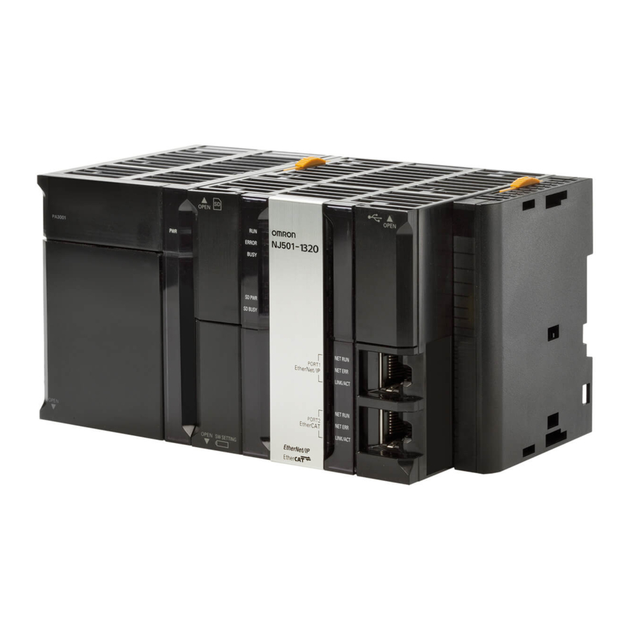
1 Introduction 1-3-2 Part Names and Functions Parts and Names NX701 CPU Unit ERROR BUSY SHTDWN SD PWR SD BUSY PORT1 EtherNet/IP NET RUN Indicators NET ERR LINK/ACT PORT1 EtherNet/IP PORT2 PORT3 EtherNet/IP EtherCAT NET RUN NET RUN Built-in EtherNet/IP USB port NET ERR NET ERR... - Page 47 1 Introduction LOT NO. DDMYY xxxx Ver.2.00 PORT1 MAC ADDRESS: PORT2 MAC ADDRESS: addresses NX102 CPU Unit PORT1 EtherNet/IP Built-in EtherNet/IP port 1 Indicators PORT2 EtherNet/IP Built-in EtherNet/IP port 2 PORT3 EtherCAT Built-in EtherCAT port MAC Address Notation A MAC address is uniquely allocated to each device connected to the Ethernet network. The MAC address of each built-in EtherNet/IP port is represented in 12-digit hexadecimal format and listed in the place of the Unit as shown below.
- Page 48 1 Introduction LOT No. DDMYY xxxx Ver. . HW Rev. PORT1 PORT2 MAC addresses 1-14 NJ/NX-series CPU Unit Built-in EtherNet/IP Port User’s Manual (W506)
- Page 49 1 Introduction NX1P2 CPU Unit SW SETTING POWER PORT1 EtherNet/IP ERROR BUSY Built-in EtherNet/IP port SD PWR SD BUSY PORT1 EtherNet/IP NET RUN PORT2 EtherCAT NET ERR LINK/ACT PORT2 EtherCAT NETRUN NET ERR LINK/ACT Indicators MAC Address Notation A MAC address is uniquely allocated to each device connected to the Ethernet network. The MAC address of the built-in EtherNet/IP port is represented in 12-digit hexadecimal format and listed in the place of the Unit as shown below.
- Page 50 1 Introduction NJ-series CPU Unit USB port Built-in EtherNet/IP port Built-in EtherCAT port Indicators MAC Address Notation A MAC address is uniquely allocated to each device connected to the Ethernet network. The MAC address of the built-in EtherNet/IP port is represented in 12-digit hexadecimal format and listed in the two places of the Unit as shown below.
- Page 51 1 Introduction Indicators (LEDs) PORT1 SD BUSY EtherNet/IP EtherNet/IP PORT1 NET RUN NET RUN NET ERR NET ERR LINK/ACT LINK/ACT EtherCAT PORT2 PORT2 PORT3 EtherNet/IP EtherCAT NET RUN NET RUN NET ERR NET ERR LINK/ACT LINK/ACT NX701 CPU Unit NX102 CPU Unit NX1P2 CPU Unit NJ-series CPU Unit ...
- Page 52 1 Introduction Indicator Status Operating status There are no Ethernet communications errors. Not lit • The power supply is OFF or the Controller is reset. A user-recoverable error is occurring. • An error is occurring in TCP/IP communications or CIP communications. Flash- •...
-
Page 53: Introduction To Communications Services
1 Introduction Introduction to Communications Services 1-4-1 CIP (Common Industrial Protocol) Communications Services Tag Data Links (Cyclic Communications) A program is not required to perform cyclic data exchanges with other devices on the EtherNet/IP net- work. Normally, a connection is started with the target device for each tag set that was created with the Net- work Configurator to start communications for tag data links for a built-in EtherNet/IP port. - Page 54 1 Introduction CIP Message Communications User-specified CIP commands can be sent to devices on the EtherNet/IP network. CIP commands, such as those for reading and writing data, can be sent and their responses received by executing the CIP communications instructions from the user program in the NJ/NX-series CPU Unit.
-
Page 55: Ip Routing
In the case of relay hops, the timeout for the relay route must be added to the timeout for the request. OMRON products that support CIP subtract 5 seconds per hop. Version Information For NJ-series CPU Unit, you can use the EtherNet/IP Unit with the CPU unit version 1.01 or later and the Sysmac Studio version 1.02 or higher. -
Page 56: Packet Filter
1 Introduction Computer Sysmac Studio IP address: 10.1.1.1/24 IP address: 10.1.1.2/24 EtherNet/IP Network address: 10.1.1.0/24 NX701 CPU Unit or IP router NX102 CPU Unit table EtherNet/IP Network address: 10.1.2.0/24 NX701 CPU Unit or NX102 CPU Unit IP router table Network address: 10.1.3.0/24 EtherNet/IP NJ-series CPU Unit... -
Page 57: Bootp Client
1 Introduction Precautions for Correct Use • Connections to NA-series and NS-series Programmable Terminals are restricted if this func- tion is enabled. When you connect these devices, register their IP addresses for the Packet Filter setting. Refer to Packet Filter (NX102 CPU Unit) on page 5-6 for details on the set- ting. -
Page 58: Ftp Client
1 Introduction Host computer (FTP client) Ethernet FTP command Built-in EtherNet/IP port NJ-series Controller SD Memory Card Host computer to Controller Controller to Host computer File data File data SD Memory SD Memory Card Card 1-4-6 FTP Client The built-in EtherNet/IP port contains an FTP client. With it, you can use FTP client communications instructions to transfer files between the CPU Unit and host computers on Ethernet. -
Page 59: Socket Service
1 Introduction NTP server NTP command Ethernet Clock information Built-in EtherNet/IP port NJ/NX-series Controller Precautions for Correct Use An NTP server is required to use automatic clock adjustment. 1-4-8 Socket Service You can send data to and receive data from any node on Ethernet with the UDP or TCP protocol. To send/receive data with a socket service, you execute multiple socket communications instructions in sequence in an ST program to execute the required communications processes. -
Page 60: Specifying Host Names
1 Introduction 1-4-9 Specifying Host Names You can directly specify IP addresses, but you can also use the host names instead of the IP address- es for NTP servers, SNMP managers, or the destinations of socket instructions and CIP communica- tions instructions (DNS client or hosts settings). -
Page 61: Tcp/Udp Message Service
1 Introduction SNMP Trap When specific conditions occur, the built-in EtherNet/IP port that is set as the SNMP agent sends sta- tus notification reports to the SNMP manager. The SNMP manager can learn about changes in status even without periodically monitoring the built- in EtherNet/IP port. -
Page 62: Ethernet/Ip Communications Procedures
1 Introduction EtherNet/IP Communications Proce- dures Basic Operation Wire the Ethernet network with twisted-pair cable. Section 2 Installing Ethernet Net- works on page 2-1 ↓ Set the built-in EtherNet/IP port IP address with the Sysmac Section 4 Determining IP Ad- Studio. - Page 63 1 Introduction Start the tag data links (the links starts automatically when power is turned ON). ↓ Check operation. 1-3-2 Part Names and Functions on page 1-12 Section 16 Troubleshooting on page 16-1 • Check the built-in EtherNet/IP port indicators. •...
- Page 64 1 Introduction • Set the NTP settings (enabling NTP and execution condi- tions). ↓ Execute automatic clock adjustment. • Execute automatic adjustment at specified times or specified intervals. • Use the Sysmac Studio to check the NTP Last Operation Time and NTP Operation Result system-defined variables. •...
- Page 65 Installing Ethernet Networks Selecting the Network Devices ..............2-2 2-1-1 Recommended Network Devices ..............2-2 2-1-2 Ethernet Switch Types ..................2-3 2-1-3 Ethernet Switch Functions ................2-3 2-1-4 Precautions for Ethernet Switch Selection............2-4 Network Installation ..................2-7 2-2-1 Basic Installation Precautions................. 2-7 2-2-2 Recommended Network Devices ..............
-
Page 66: Selecting The Network Devices
The following table shows the devices recommended for use with the EtherNet/IP. Ethernet Switches Manufacturer Model Description OMRON W4S1-03B Packet priority control (QoS): EtherNet/IP control data priority Failure detection: Broadcast storm, LSI error detection, 100Basae-TX/ W4S1-05B 10Base-T, Auto negotiation... -
Page 67: Ethernet Switch Types
“Specific nodes” are nodes equipped with an IGMP client, and have made transfer requests to the Ethernet switch. (OMRON built-in EtherNet/IP ports are equipped with an IGMP client.) When the Ethernet switch does not use multicast filtering, multicast packets are sent to all nodes, just like broadcast packets, which increases the traffic in the network. -
Page 68: Precautions For Ethernet Switch Selection
Managed L2 Ethernet switch Supported Supported Both functions must be set with a special software tool. OMRON Ethernet switch Not supported Supported L4 QoS is set with a switch. (W4S1-series Ethernet switches) No software tool is necessa- Additional Information If the Network Configurator is used to set the connection type in the connection settings to a Multicast Connection, multicast packets are used. - Page 69 2 Installing Ethernet Networks When multicast filtering is used, settings must be made accordingly on the Ethernet switch. There must be enough multicast filters for the network. Executing Tag Data Links and Message Communications We recommend an L2 Ethernet switch with multicast filtering and L4 QoS. If you set tag data links for higher-priority transmission, it is possible to prevent problems such as transmission delays due to message communications traffic and packet losses due to buffer over- flow.
- Page 70 2 Installing Ethernet Networks Selecting the Ethernet Switch Based on the Network Communica- tion Speed Executing Tag Data Links at a Baud Rate Over 100 Mbps If you use data tag links with the following conditions, use an Ethernet switch with multicast filtering or an Ethernet switch that supports a baud rate of 1,000 Mbps.
-
Page 71: Network Installation
2 Installing Ethernet Networks Network Installation 2-2-1 Basic Installation Precautions • Take the greatest care when you install the Ethernet System. Be sure to follow ISO 8802-3 specifi- cations. Be sure you understand them before attempting to install an Ethernet System. •... - Page 72 2 Installing Ethernet Networks NJ-series CPU Unit NX-series CPU Unit 1000Base-T 10Base-T 100Base-TX 10Base-T 100Base-TX • • Connect the shield Connect the shield at both ends Connect the shield at both ends at both ends • • Connect the shield only at the Ethernet Connect the shield only at the Ethernet switch side switch side.
- Page 73 2 Installing Ethernet Networks Ethernet switches Connect shield to connector hood Connector Connector Connector Do not connect shield to connector hood terminal Built-in EtherNet/IP Power Supply port on NX-series Unit CPU Unit Clamp core Connector (Shield) terminal Built-in EtherNet/IP Built-in EtherNet/IP Power Supply port port on NJ-series...
- Page 74 2 Installing Ethernet Networks Between Two Ethernet Switches Regardless of which baud rate is used, check with the Ethernet switch manufacturers for informa- tion about installing the network between Ethernet switches, and in particular whether or not it is necessary to connect the cable shields to the connector hoods.
-
Page 75: Precautions When Installing And Connecting Ethernet Switches
2 Installing Ethernet Networks Built-in EtherNet/IP Attach close to the cable port on connection as shown. NX-series Controller 2-2-4 Precautions When Installing and Connecting Ethernet Switches Precautions When Installing Ethernet Switches • Do not ground the Ethernet switch in the same location as a drive-system component, such as an inverter. - Page 76 2 Installing Ethernet Networks Precautions for Correct Use Adjust the built-in EtherNet/IP port's link settings to match the communications mode settings of the connected Ethernet switch. If the settings do not match, the link will be unstable and prevent normal communications. The following table shows the allowed settings for each Ethernet switch communications mode.
-
Page 77: Connecting To The Network
2 Installing Ethernet Networks Connecting to the Network 2-3-1 Ethernet Connectors The following standards and specifications apply to the connectors for the Ethernet twisted-pair cable. • Electrical specifications: Conforming to IEEE 802.3 standards. • Connector structure: RJ45 8-pin Modular Connector (conforming to ISO 8877) •... - Page 78 2 Installing Ethernet Networks Install the twisted-pair cable. Connect the cable to the Ethernet switch. Connect the twisted-pair cable to the connector on the built-in EtherNet/IP port. Be sure to press the connectors (both the Ethernet switch side and Ethernet side) until they lock into place.
-
Page 79: System-Defined Variables Related To The Built-In Ethernet/Ip Port
System-defined Variables Related to the Built-in EtherNet/IP Port System-defined Variables Related to the Built-in EtherNet/IP Port ... 3-2 System-defined Variables................3-3 Specifications for Individual System-defined Variables......3-36 NJ/NX-series CPU Unit Built-in EtherNet/IP Port User’s Manual (W506) - Page 80 3 System-defined Variables Related to the Built-in EtherNet/IP Port System-defined Variables Related to the Built-in EtherNet/IP Port You can use the system-defined variables that are provided for the built-in EtherNet/IP port in pro- grams to check the status of the built-in EtherNet/IP port. ...
-
Page 81: System-Defined Variables
3 System-defined Variables Related to the Built-in EtherNet/IP Port System-defined Variables The variables are described in the tables as shown below. Range of Variable name Meaning Function Data type Reference values This is the system- This is the mean- The function of the variable is descri- The data The range The page of... - Page 82 3 System-defined Variables Related to the Built-in EtherNet/IP Port Range of Variable name Meaning Function Data type Reference values _EIP_PortErr Communications Port This is the error status variable for the WORD 16#0000 to page 3-37 Error communications port. 16#00F0 NX-series CPU Units: Represents the collective status of the following error flags.
- Page 83 3 System-defined Variables Related to the Built-in EtherNet/IP Port Range of Variable name Meaning Function Data type Reference values _EIP1_PortErr Communications This is the error status variable for the WORD 16#0000 to page 3-37 Port1 Error communications port 1. 16#00F0 It represents the collective status of the following error flags.
- Page 84 3 System-defined Variables Related to the Built-in EtherNet/IP Port Range of Variable name Meaning Function Data type Reference values _EIP2_PortErr Communications This is the error status variable for the WORD 16#0000 to page 3-38 Port2 Error communications port 2. 16#00F0 It represents the collective status of the following error flags.
- Page 85 3 System-defined Variables Related to the Built-in EtherNet/IP Port Range of Variable name Meaning Function Data type Reference values _EIP_CipErr CIP Communications This is the error status variable for CIP WORD 16#0000 to page 3-38 Error communications. 16#00F0 NX-series CPU Units: Represents the collective status of the following error flags.
- Page 86 3 System-defined Variables Related to the Built-in EtherNet/IP Port Range of Variable name Meaning Function Data type Reference values _EIP1_CipErr CIP Communica- This is the error status variable for CIP WORD 16#0000 to page 3-39 tions1 Error communications 1. 16#00F0 It represents the collective status of the following error flags.
- Page 87 3 System-defined Variables Related to the Built-in EtherNet/IP Port Range of Variable name Meaning Function Data type Reference values _EIP_TcpAppErr TCP Application This is the error status variable for TCP WORD 16#0000 to page 3-39 Communications Er- application communications. 16#00F0 It represents the collective status of the following error flags.
- Page 88 3 System-defined Variables Related to the Built-in EtherNet/IP Port Range of Variable name Meaning Function Data type Reference values _EIP2_LanHwErr Port2 Communica- Indicates that a communications control- BOOL TRUE or page 3-41 tions Controller Error ler failure occurred on the communica- FALSE tions port 2.
- Page 89 3 System-defined Variables Related to the Built-in EtherNet/IP Port Range of Variable name Meaning Function Data type Reference values _EIP_IPAdrCfgErr IP Address Setting NX-series CPU Units: Indicates the IP BOOL TRUE or page 3-42 Error address setting errors for the communi- FALSE cations port 1.
- Page 90 3 System-defined Variables Related to the Built-in EtherNet/IP Port Range of Variable name Meaning Function Data type Reference values _EIP1_IPAdrDupErr Port1 IP Address Du- Indicates that the same IP address is as- BOOL TRUE or page 3-43 plication Error signed to more than one node for the FALSE communications port 1.
- Page 91 3 System-defined Variables Related to the Built-in EtherNet/IP Port Range of Variable name Meaning Function Data type Reference values _EIP2_BootpErr Port2 BOOTP Server Indicates that a BOOTP server connec- BOOL TRUE or page 3-44 Error tion failure occurred on the communica- FALSE tions port 2.
- Page 92 3 System-defined Variables Related to the Built-in EtherNet/IP Port Range of Variable name Meaning Function Data type Reference values _EIP_TDLinkCfgErr Tag Data Link Setting NX-series CPU Units: Indicates that the BOOL TRUE or page 3-46 Error tag data link settings for CIP communica- FALSE tions 1 are incorrect.
- Page 93 3 System-defined Variables Related to the Built-in EtherNet/IP Port Range of Variable name Meaning Function Data type Reference values _EIP1_TDLinkOp- CIP Communica- Indicates that establishing a tag data link BOOL TRUE or page 3-47 nErr tions1 Tag Data Link connection for CIP communications 1 FALSE Connection Failed failed.
- Page 94 3 System-defined Variables Related to the Built-in EtherNet/IP Port Range of Variable name Meaning Function Data type Reference values _EIP2_TDLinkErr CIP Communica- Indicates that a timeout occurred in a tag BOOL TRUE or page 3-48 tions2 Tag Data Link data link connection for CIP communica- FALSE Communications Er- tions 2.
- Page 95 3 System-defined Variables Related to the Built-in EtherNet/IP Port Range of Variable name Meaning Function Data type Reference values _EIP1_TagAdrErr CIP Communica- Indicates that the tag resolution for CIP BOOL TRUE or page 3-49 tions1 Tag Name communications 1 failed (i.e., the ad- FALSE Resolution Error dress could not be identified from the tag...
- Page 96 3 System-defined Variables Related to the Built-in EtherNet/IP Port Range of Variable name Meaning Function Data type Reference values _EIP1_MultiSwO- CIP Communica- Indicates that more than one switch BOOL TRUE or page 3-50 NErr tions1 Multiple turned ON at the same time in CIP com- FALSE Switches ON Error munications 1.
- Page 97 3 System-defined Variables Related to the Built-in EtherNet/IP Port Level 1 Level 2 Level 3 Variable Name Variable Name Variable Name _EIP_ErrSta Built-in Ether- _EIP_Por- Communi- _EIP_MacAdrErr MAC Address Error Net/IP Error tErr cations _EIP_LanHwErr Communications Controller Error Port Error _EIP_EtnCfgErr Basic Ethernet Setting Error _EIP_IPAdrCfgErr...
- Page 98 3 System-defined Variables Related to the Built-in EtherNet/IP Port Level 1 Level 2 Level 3 Variable Name Variable Name Variable Name _EIP_ErrSta Built-in Ether- _EIP1_Po Communi- _EIP1_MacAdrErr Port1 MAC Address Error Net/IP Error rtErr cations _EIP1_LanHwErr Port1 Communications Controller Port1 Er- Error _EIP1_EtnCfgErr Port1 Basic Ethernet Setting Error...
- Page 99 3 System-defined Variables Related to the Built-in EtherNet/IP Port Meanings of Error Status Bits The meanings of the individual bits in the following error status are the same. • _ErrSta (Controller Error Status) • _PLC_ErrSta (PLC Function Module Error Status) •...
- Page 100 3 System-defined Variables Related to the Built-in EtherNet/IP Port Meaning This bit indicates whether a major fault level Controller error has occurred. TRUE: A major fault level Controller error has occurred. FALSE: A major fault level Controller error has not occurred. This bit indicates whether a partial fault level Controller error has occurred.
- Page 101 3 System-defined Variables Related to the Built-in EtherNet/IP Port Range of Variable name Meaning Function Data type Reference values _EIP2_EtnOnlineSta Port2 Online Indicates that the built-in EtherNet/IP BOOL TRUE or page 3-52 port's communications can be used via FALSE the communications port 2 (that is, the link is ON, IP address is defined, and there are no errors.) TRUE: The built-in EtherNet/IP port’s...
- Page 102 3 System-defined Variables Related to the Built-in EtherNet/IP Port Range of Variable name Meaning Function Data type Reference values _EIP1_TDLinkAll- CIP Communica- Indicates that all tag data links are com- BOOL TRUE or page 3-53 RunSta tions1 All Tag Data municating in CIP communications 1.
- Page 103 3 System-defined Variables Related to the Built-in EtherNet/IP Port Range of Variable name Meaning Function Data type Reference values _EIP2_RegTarget- CIP Communica- Gives a list of nodes for which built-in ARRAY TRUE or page 3-54 Sta[255] tions2 Registered EtherNet/IP connections are registered [0..255] OF FALSE Target Node Informa-...
- Page 104 3 System-defined Variables Related to the Built-in EtherNet/IP Port Range of Variable name Meaning Function Data type Reference values _EIP2_EstbTarget- CIP Communica- Gives a list of nodes that have normally ARRAY TRUE or page 3-55 Sta[255] tions2 Normal Target established built-in EtherNet/IP connec- [0..255] OF FALSE Node Information...
- Page 105 3 System-defined Variables Related to the Built-in EtherNet/IP Port Range of Variable name Meaning Function Data type Reference values _EIP1_TargetPLC- CIP Communica- Shows the operating status of the target ARRAY TRUE or page 3-56 ModeSta[255] tions1 Target PLC node Controllers that are connected for [0..255] OF FALSE Operating Mode...
- Page 106 3 System-defined Variables Related to the Built-in EtherNet/IP Port Range of Variable name Meaning Function Data type Reference values _EIP_TargetPL- Target PLC Error In- NX-series CPU Units: Shows the error ARRAY TRUE or page 3-57 CErr[255] formation status (logical OR of fatal and non-fatal [0..255] OF FALSE errors) of the target node Controllers that...
- Page 107 3 System-defined Variables Related to the Built-in EtherNet/IP Port Range of Variable name Meaning Function Data type Reference values _EIP2_TargetPL- CIP Communica- Shows the error status (logical OR of fa- ARRAY TRUE or page 3-57 CErr[255] tions2 Target PLC Er- tal and non-fatal errors) of the target [0..255] OF FALSE...
- Page 108 3 System-defined Variables Related to the Built-in EtherNet/IP Port Range of Variable name Meaning Function Data type Reference values _EIP_TargetNo- Target Node Error In- NX-series CPU Units: Indicates that the ARRAY TRUE or page 3-58 deErr[255] formation connection for the Registered Target [0..255] OF FALSE Node Information for CIP communica-...
- Page 109 3 System-defined Variables Related to the Built-in EtherNet/IP Port Range of Variable name Meaning Function Data type Reference values _EIP1_TargetNo- CIP Communica- Indicates that the connection for the Reg- ARRAY TRUE or page 3-58 deErr[255] tions1 Target Node istered Target Node Information for CIP [0..255] OF FALSE Error Information...
- Page 110 3 System-defined Variables Related to the Built-in EtherNet/IP Port Range of Variable name Meaning Function Data type Reference values _EIP2_TargetNo- CIP Communica- Indicates that the connection for the Reg- ARRAY TRUE or page 3-59 deErr[255] tions2 Target Node istered Target Node Information for CIP [0..255] OF FALSE Error Information...
- Page 111 3 System-defined Variables Related to the Built-in EtherNet/IP Port Precautions for Correct Use Communications Status with Target Node The communications status with the target node of an NJ/NX-series Controller is shown by the combination of the values of four system-defined variables. •...
- Page 112 3 System-defined Variables Related to the Built-in EtherNet/IP Port Functional Classification: EtherNet/IP Communications Switches Range of Variable name Meaning Function Data type Reference values _EIP_TDLink- Tag Data Link Com- NX-series CPU Units: Change this varia- BOOL TRUE or page 3-60 StartCmd munications Start ble to TRUE to start tag data links for CIP...
- Page 113 3 System-defined Variables Related to the Built-in EtherNet/IP Port Range of Variable name Meaning Function Data type Reference values _EIP1_TDLink- CIP Communica- Change this variable to TRUE to stop tag BOOL TRUE or page 3-61 StopCmd tions1 Tag Data Link data links for CIP communications 1.
-
Page 114: Specifications For Individual System-Defined Variables
3 System-defined Variables Related to the Built-in EtherNet/IP Port Specifications for Individual System- defined Variables The specifications for each system-defined variable are given as described below. Variable name This is the system-defined variable name. Members The member names are given The prefix gives the category name. - Page 115 3 System-defined Variables Related to the Built-in EtherNet/IP Port Variable name _EIP_PortErr Meaning Communications Port Error Global/local Global Function This is the error status variable for the communications port. NX-series CPU Units: Represents the collective status of the following error flags. •...
- Page 116 3 System-defined Variables Related to the Built-in EtherNet/IP Port Variable name _EIP2_PortErr Meaning Communications Port2 Error Global/local Global Function This is the error status variable for the communications port 2. It represents the collective status of the following error flags. •...
- Page 117 3 System-defined Variables Related to the Built-in EtherNet/IP Port Variable name _EIP1_CipErr Meaning CIP Communications1 Error Global/local Global Function This is the error status variable for CIP communications 1. It represents the collective status of the following error flags. • _EIP1_IdentityErr (CIP Communications1 Identity Error) •...
- Page 118 3 System-defined Variables Related to the Built-in EtherNet/IP Port Variable name _EIP_MacAdrErr Meaning MAC Address Error Global/local Global Function NX-series CPU Units: Indicates that an error occurred when the MAC address was read on the communications port 1 at startup. TRUE: Error FALSE: Normal NJ-series CPU Units: Indicates that an error occurred when the MAC address was read at startup.
- Page 119 3 System-defined Variables Related to the Built-in EtherNet/IP Port Variable name _EIP1_LanHwErr Meaning Port1 Communications Controller Error Global/local Global Function Indicates that a communications controller failure occurred on the communications port 1. TRUE: Failure FALSE: Normal Note You can use this system-defined variable only for NX-series CPU Units. Data type BOOL Range of values...
- Page 120 3 System-defined Variables Related to the Built-in EtherNet/IP Port Variable name _EIP2_EtnCfgErr Meaning Port2 Basic Ethernet Setting Error Global/local Global Function Indicates that the Ethernet communications speed setting (Speed/Duplex) for the communications port 2 is incor- rect. Or, a read operation failed. TRUE: Setting incorrect or read failed.
- Page 121 3 System-defined Variables Related to the Built-in EtherNet/IP Port Variable name _EIP2_IPAdrCfgErr Meaning Port2 IP Address Setting Error Global/local Global Function Indicates the IP address setting errors for the communications port 2. TRUE: • There is an illegal IP address setting. •...
- Page 122 3 System-defined Variables Related to the Built-in EtherNet/IP Port Variable name _EIP_DNSCfgErr Meaning DNS Setting Error Global/local Global Function Indicates that the DNS or hosts settings are incorrect. Or, a read operation failed. TRUE: Setting incorrect or read failed. FALSE: Normal Data type BOOL Range of values...
- Page 123 3 System-defined Variables Related to the Built-in EtherNet/IP Port Variable name _EIP_IPRTblErr Meaning IP Route Table Error Global/local Global Function NX-series CPU Units: Indicates that the default gateway settings or IP router table settings are incorrect. Or, a read operation failed. TRUE: Setting incorrect or read failed.
- Page 124 3 System-defined Variables Related to the Built-in EtherNet/IP Port Variable name _EIP_TDLinkCfgErr Meaning Tag Data Link Setting Error Global/local Global Function NX-series CPU Units: Indicates that the tag data link settings for CIP communications 1 are incorrect. Or, a read operation failed.
- Page 125 3 System-defined Variables Related to the Built-in EtherNet/IP Port Variable name _EIP_TDLinkOpnErr Meaning Tag Data Link Connection Failed Global/local Global Function NX-series CPU Units: Indicates that establishing a tag data link connection for CIP communications 1 failed. TRUE: Establishing a tag data link connection failed due to one of the following causes. •...
- Page 126 3 System-defined Variables Related to the Built-in EtherNet/IP Port Variable name _EIP_TDLinkErr Meaning Tag Data Link Communications Error Global/local Global Function NX-series CPU Units: Indicates that a timeout occurred in a tag data link connection for CIP communications 1. TRUE: A timeout occurred. FALSE: Other than the above.
- Page 127 3 System-defined Variables Related to the Built-in EtherNet/IP Port Variable name _EIP_TagAdrErr Meaning Tag Name Resolution Error Global/local Global Function NX-series CPU Units: Indicates that the tag resolution for CIP communications 1 failed (i.e., the address could not be identified from the tag name). TRUE: Tag resolution failed (i.e., the address could not be identified from the tag name).
- Page 128 3 System-defined Variables Related to the Built-in EtherNet/IP Port Variable name _EIP2_TagAdrErr Meaning CIP Communications2 Tag Name Resolution Global/local Global Error Function Indicates that the tag resolution for CIP communications 2 failed (i.e., the address could not be identified from the tag name).
- Page 129 3 System-defined Variables Related to the Built-in EtherNet/IP Port Variable name _EIP_TcpAppCfgErr Meaning TCP Application Setting Error Global/local Global Function TRUE: At least one of the set values for a TCP application (FTP, NTP, SNMP) is incorrect. Or, a read operation failed.
- Page 130 3 System-defined Variables Related to the Built-in EtherNet/IP Port Variable name _EIP1_EtnOnlineSta Meaning Port1 Online Global/local Global Function Indicates that the built-in EtherNet/IP port's communications can be used via the communications port 1 (that is, the link is ON, IP address is defined, and there are no errors.) TRUE: The built-in EtherNet/IP port’s communications can be used.
- Page 131 3 System-defined Variables Related to the Built-in EtherNet/IP Port Variable name _EIP2_TDLinkRunSta Meaning CIP Communications2 Tag Data Link Communi- Global/local Global cations Status Function Indicates that at least one connection is in normal operation in CIP communications 2. TRUE: Normal operation FALSE: Other than the above.
- Page 132 3 System-defined Variables Related to the Built-in EtherNet/IP Port Variable name _EIP_RegTargetSta[255] Meaning Registered Target Node Information Global/local Global Function NX-series CPU Units: Gives a list of nodes for which built-in EtherNet/IP connections are registered for CIP com- munications 1. This variable is valid only when the built-in EtherNet/IP port is the originator.
- Page 133 3 System-defined Variables Related to the Built-in EtherNet/IP Port Variable name _EIP_EstbTargetSta[255] Meaning Normal Target Node Information Global/local Global Function NX-series CPU Units: Gives a list of nodes that have normally established built-in EtherNet/IP connections for CIP communications 1. Array[x] is TRUE: The connection to the node with a target node ID of x was established normally. Array[x] is FALSE: The connection to the node with a target node ID of x was not established, or an error occur- red.
- Page 134 3 System-defined Variables Related to the Built-in EtherNet/IP Port Variable name _EIP_TargetPLCModeSta[255] Meaning Target PLC Operating Mode Global/local Global Function NX-series CPU Units: Shows the operating status of the target node Controllers that are connected for CIP com- munications 1, with the built-in EtherNet/IP port as the originator. The array elements are valid only when the corresponding Normal Target Node Information is TRUE.
- Page 135 3 System-defined Variables Related to the Built-in EtherNet/IP Port Variable name _EIP_TargetPLCErr[255] Meaning Target PLC Error Information Global/local Global Function NX-series CPU Units: Shows the error status (logical OR of fatal and non-fatal errors) of the target node Control- lers that are connected for CIP communications 1, with the built-in EtherNet/IP ports as the originator. The array elements are valid only when the corresponding Normal Target Node Information is TRUE.
- Page 136 3 System-defined Variables Related to the Built-in EtherNet/IP Port Variable name _EIP_TargetNodeErr[255] Meaning Target Node Error Information Global/local Global Function NX-series CPU Units: Indicates that the connection for the Registered Target Node Information for CIP communi- cations 1 was not established or that an error occurred in the target Controller. The array elements are valid only when the Registered Target Node Information is TRUE.
- Page 137 3 System-defined Variables Related to the Built-in EtherNet/IP Port Variable name _EIP2_TargetNodeErr[255] Meaning CIP Communications2 Target Node Error Infor- Global/local Global mation Function Indicates that the connection for the Registered Target Node Information for CIP communications 2 was not es- tablished or that an error occurred in the target Controller.
- Page 138 3 System-defined Variables Related to the Built-in EtherNet/IP Port Functional Classification: EtherNet/IP Communications Switches Variable name _EIP_TDLinkStartCmd Meaning Tag Data Link Communications Start Switch Global/local Global Function NX-series CPU Units: Change this variable to TRUE to start tag data links for CIP communications 1. It automatically changes back to FALSE after tag data link operation starts.
- Page 139 3 System-defined Variables Related to the Built-in EtherNet/IP Port Variable name _EIP1_TDLinkStopCmd Meaning CIP Communications1 Tag Data Link Communi- Global/local Global cations Stop Switch Function Change this variable to TRUE to stop tag data links for CIP communications 1. It automatically changes back to FALSE after tag data link operation stops. Note Do not force this switch to change to FALSE from the user program or from the Sysmac Studio.
- Page 140 3 System-defined Variables Related to the Built-in EtherNet/IP Port 3-62 NJ/NX-series CPU Unit Built-in EtherNet/IP Port User’s Manual (W506)
-
Page 141: Determining Ip Addresses
Determining IP Addresses IP Addresses ....................4-2 4-1-1 IP Address Configuration................4-2 4-1-2 Allocating IP Addresses.................. 4-2 4-1-3 Subnet Mask....................4-2 4-1-4 CIDR ....................... 4-3 Built-in EtherNet/IP Port IP Address Settings ..........4-5 4-2-1 Determining IP Addresses ................4-5 4-2-2 Setting IP Addresses .................. -
Page 142: Ip Addresses
4 Determining IP Addresses IP Addresses 4-1-1 IP Address Configuration IP addresses are made up of 32 bits of binary data that specify the network number (net ID) and host number (host ID). The net ID is an address used for identifying a network. The host ID is an address used for identifying a host (node). -
Page 143: Cidr
4 Determining IP Addresses To establish subnetworks, the host ID in the IP address is divided into a subnet ID and a host ID by using a setting called the subnet mask. The subnet mask indicates which part of the host ID is to be used as the subnet ID. All bits in the sub- net mask that correspond to the bits in the IP address used either as the network ID or subnet ID are set to "1", and the remaining bits, which correspond to the bits in the IP address actually used for the host ID, are set to "0". - Page 144 4 Determining IP Addresses IP addresses that use classes are separated into blocks according to network IDs and host IDs, result- ing in inefficient usage of IP address space. CIDR does not use classes, so IP address space can be divided as required to more efficiently use IP address space.
-
Page 145: Built-In Ethernet/Ip Port Ip Address Settings
4 Determining IP Addresses Built-in EtherNet/IP Port IP Address Settings 4-2-1 Determining IP Addresses Use one of the following methods to set an IP address of a built-in EtherNet/IP port. Setting a User-specified IP Address If you need to change the default IP address of the built-in EtherNet/IP port or if you need to use the built-in EtherNet/IP port with another EtherNet/IP node, set the IP address to a required value. - Page 146 4 Determining IP Addresses Used to set a user-specified IP address. Used to obtain the IP address from the BOOTP server each time the power is turned ON. Used to obtain the IP address from the BOOTP server once and then not change it. Display when using the NJ-series CPU Unit For an NX701 CPU Unit and an NX102 CPU Unit, the IP addresses must be set separately for built-in EtherNet/IP ports 1 and 2.
- Page 147 4 Determining IP Addresses Additional Information If you cannot obtain the IP address from the BOOTP server or the obtained IP address is not correct, select the Fixed setting Option in the IP Address Area and manually set the IP address, subnet mask, and default gateway.
-
Page 148: Online Connection
4 Determining IP Addresses Additional Information For an NJ-series CPU Unit, NX102 CPU Unit, and NX1P2 CPU Unit, when the local IP address of the built-in EtherNet/IP port is set, the FINS node address is automatically set as shown be- low. - Page 149 4 Determining IP Addresses Direct Connection via Ethernet (1:1 Connection Ethernet Connection via Hub (1:N Connection) with AutoIP) Ethernet Ethernet *1. An Ethernet switch is required to connect. Refer to 2-1-4 Precautions for Ethernet Switch Selec- *1. An Ethernet switch is not necessarily required. tion on page 2-4 for details.
- Page 150 4 Determining IP Addresses Select Controller - Communications Setup and click the OK Button in the Sysmac Studio Project Window. 1:1 Connection 1:N Connection Ethernet Connection Direct Connection ·Remote connection via USB ·Direct connection via USB EtherNet/IP Connection ·Ethernet connection via hub ·Direct connection via Ethernet Additional Information If there is any error in the set IP address, the CPU Unit behaves as follows:...
-
Page 151: Checking The Current Ip Address
4 Determining IP Addresses 4-2-4 Checking the Current IP Address The current IP address can be confirmed in the Controller Status Pane of the Sysmac Studio, whether it is manually set or obtained from the BOOTP server. Display when using the NJ-series CPU Units and NX1P2 CPU Units •... -
Page 152: Private And Global Addresses
4 Determining IP Addresses Private and Global Addresses 4-3-1 Private and Global Addresses There are two kinds of IP addresses, private and global. Global address These are IP addresses that connect directly to the Internet. Allocated by applica- tion to NIC, each address is unique in the world, and as many as 4.3 billion can be allocated worldwide. -
Page 153: Using A Private Address For The Built-In Ethernet/Ip Port
4 Determining IP Addresses 4-3-2 Using a Private Address for the Built-in EtherNet/IP Port Intranet Personal computer (e.g., Sysmac Studio) Ethernet (EtherNet/IP) Firewall Controller Private address IP router Private address Cannot connect to Internet Internet Global address (required) Intranet Cannot connect to Internet Global address IP router Private address... -
Page 154: Using A Global Address For The Built-In Ethernet/Ip Port
4 Determining IP Addresses 4-3-3 Using a Global Address for the Built-in EtherNet/IP Port Intranet CIP client on a computer, such as Network Configurator Ethernet (EtherNet/IP) Communications Firewall over Internet Private address IP router Cannot connect to Internet Internet Global address (required) Cannot connect to Internet Intranet... -
Page 155: Sysmac Studio Settings For The Built-In Ethernet/Ip Port
Sysmac Studio Settings for the Built-in EtherNet/IP Port TCP/IP Settings Display................. 5-2 LINK Settings Display ..................5-8 FTP Settings Display ..................5-9 NTP Settings Display ................... 5-10 SNMP Settings Display ................5-12 SNMP Trap Settings Display ............... 5-14 NJ/NX-series CPU Unit Built-in EtherNet/IP Port User’s Manual (W506) -
Page 156: Tcp/Ip Settings Display
5 Sysmac Studio Settings for the Built-in EtherNet/IP Port TCP/IP Settings Display NX-series CPU Unit NJ-series CPU Unit IP Address - Port 1 (NX-series CPU Unit) Set an IP address for the built-in EtherNet/IP port 1. Setting Description Default IP address setting Select one of the following IP address setting methods for Fixed setting... - Page 157 5 Sysmac Studio Settings for the Built-in EtherNet/IP Port Setting Description Default IP address setting Select one of the following IP address setting methods for the built-in Fixed setting method EtherNet/IP port 2. • Fixed setting • Obtain from BOOTP server. •...
- Page 158 5 Sysmac Studio Settings for the Built-in EtherNet/IP Port Operation at IP Address Duplication Setting Description Default Use of duplicated IP ad- When you set an IP address for the built-in EtherNet/IP port and Stop dress find an IP address conflict with another node, select whether to stop the use of the IP address.
- Page 159 5 Sysmac Studio Settings for the Built-in EtherNet/IP Port Keep Alive Setting Description Default Keep Alive Set whether to use the remote node Keep Alive function of con- nected servers and clients (such as socket service, FTP server, Sysmac Studio, and FINS/TCP) for each connection number. If the Use Option is selected for Keep Alive and no communica- tions are performed with the remote node for the Keep Alive monitoring time, transmission of Keep Alive packets is started.
- Page 160 5 Sysmac Studio Settings for the Built-in EtherNet/IP Port Additional Information IP Router Table Setting Example Set the following IP router table in node A to use tag data links or CIP message communica- tions between node A and node B through the IP router. If you set the IP router table and execute a communications instruction from node A to node B, node A sends packets addressed to the gateway IP address (130.25.36.253).
- Page 161 5 Sysmac Studio Settings for the Built-in EtherNet/IP Port Precautions for Correct Use • Connections to NA-series and NS-series Programmable Terminals are restricted if this func- tion is enabled. To make connections to these devices, register their IP addresses in the Packet Filter settings.
-
Page 162: Link Settings Display
5 Sysmac Studio Settings for the Built-in EtherNet/IP Port LINK Settings Display NX701 CPU Unit NJ-series CPU Unit NX102 CPU Unit NX1P2 CPU Unit LINK Settings - Port 1 and Port 2 (NX701 and NX102 CPU Units) Set for each built-in EtherNet/IP port. Setting Description Default... -
Page 163: Ftp Settings Display
5 Sysmac Studio Settings for the Built-in EtherNet/IP Port FTP Settings Display Setting Description Default FTP server Specify whether to use the FTP server or not. Do not use FTP connections from external devices will not be possible if the Do not use Option is selected. -
Page 164: Ntp Settings Display
5 Sysmac Studio Settings for the Built-in EtherNet/IP Port NTP Settings Display Setting Description Default NTP server clock infor- Set whether to obtain clock information from the NTP server to up- Do not get mation date the clock in the CPU Unit. Set the port number to use to connect to the NTP server to obtain *1 *2 Port No. - Page 165 5 Sysmac Studio Settings for the Built-in EtherNet/IP Port Setting Description Default Timeout time (sec- Set the timeout detection time. 10 seconds (Setting range: 1 to 255 seconds) onds) If the remote host does not respond, retry processing is performed four times within the time interval that is set here.
-
Page 166: Snmp Settings Display
5 Sysmac Studio Settings for the Built-in EtherNet/IP Port SNMP Settings Display SNMP Setting Description Default SNMP service Do not use Specify whether to use the SNMP monitor service. If the Do not use Option is selected, an SNMP manager cannot connect from an external device. - Page 167 5 Sysmac Studio Settings for the Built-in EtherNet/IP Port Recognition 1 Setting Description Default Recognition method Set the method to use to specify SNMP managers for which ac- IP address cess is permitted. • IP address • Host name Make these settings to permit access by only certain SNMP managers.
-
Page 168: Snmp Trap Settings Display
5 Sysmac Studio Settings for the Built-in EtherNet/IP Port SNMP Trap Settings Display SNMP Trap Setting Description Default SNMP trap Specify whether to use the SNMP trap (network error detec- Do not use tion). If the Do not use Option is selected for SNMP trap, SNMP traps are not sent to the SNMP manager Set the port number to use to connect to the SNMP server. - Page 169 5 Sysmac Studio Settings for the Built-in EtherNet/IP Port Setting Description Default Community name Set the community name. public (You can use up to 255 single-byte alphanumeric characters.) Version Set the version of the SNMP manager. SNMPv1 • SNMPv1 • SNMPv2C ...
- Page 170 5 Sysmac Studio Settings for the Built-in EtherNet/IP Port 5-16 NJ/NX-series CPU Unit Built-in EtherNet/IP Port User’s Manual (W506)
- Page 171 Testing Communications Testing Communications................6-2 6-1-1 PING Command ..................... 6-2 6-1-2 Using the PING Command ................6-2 6-1-3 Host Computer Operation................6-2 NJ/NX-series CPU Unit Built-in EtherNet/IP Port User’s Manual (W506)
-
Page 172: Ping Command
6 Testing Communications Testing Communications If the basic settings (in particular the IP address and subnet mask) have been made correctly for the built-in EtherNet/IP port, then it is possible to communicate with nodes on the EtherNet/IP network. This section describes how to use the PING command to test communications with the built-in Ether- Net/IP port. - Page 173 6 Testing Communications The destination is specified by its IP address or host name. Additional Information The PING command is not supported by some host computers. Application Example In this example, a PING command is sent to the node at IP address 130.25.36.8. The "$"...
- Page 174 6 Testing Communications NJ/NX-series CPU Unit Built-in EtherNet/IP Port User’s Manual (W506)
- Page 175 Tag Data Link Functions Introduction to Tag Data Links..............7-2 7-1-1 Tag Data Links ....................7-2 7-1-2 Data Link Data Areas..................7-3 7-1-3 Tag Data Link Functions and Specifications ........... 7-6 7-1-4 Overview of Operation ..................7-7 7-1-5 Starting and Stopping Tag Data Links ............7-9 7-1-6 Controller Status ...................
-
Page 176: Introduction To Tag Data Links
7 Tag Data Link Functions Introduction to Tag Data Links 7-1-1 Tag Data Links Tag data links enable cyclic tag data exchanges on an EtherNet/IP network between Controllers or be- tween Controllers and other devices. Variables are assigned to tags. (You can also assign I/O memory addresses to tags.) The settings for tag data links are made with the Network Configurator. -
Page 177: Data Link Data Areas
7 Tag Data Link Functions The size of data for data exchange is the total size of tags included in the tag set. The size of the out- put tag set and the size of the input tag set must match. 7-1-2 Data Link Data Areas Tags... - Page 178 7 Tag Data Link Functions Originator device Target device IP address: N Connection Information Target IP address: N Originator tag set SP1_IN Target tag set: SP1_OUT Packet interval (RPI) Tag set (input) Tag set (output) Tag set name: SP1_IN Tag set name: SP1_OUT Controller Status Controller Status Tag “i”...
- Page 179 7 Tag Data Link Functions CJ-series CPU Unit NJ/NX-series CPU Unit I/O memory Tag set SP1_IN Tag set SP1_OUT (tag a) (tag c) Connection Variable a Variable c Individual tags Tag set SP2_OUT Tag set SP2_IN (tag b) (tag d) Connection Variable b Variable d...
-
Page 180: Tag Data Link Functions And Specifications
7 Tag Data Link Functions 7-1-3 Tag Data Link Functions and Specifications The tag data link and performance specifications of the NJ/NX-series CPU Unit are given below. Specification NJ501-££££/NJ301-£££ Item £/NJ101-££££ NX701-£££ NX102-£££ NX1P2-£££ £ £ ££££ Unit version Unit version 1.00 to 1.02 1.03 or later Communications type... -
Page 181: Overview Of Operation
7 Tag Data Link Functions specify the variable with the AT specification for the tag. For NX102 and NX1P2 CPU Units, you need to set CJ memory to use the I/O memory address. For details on CJ memory setting, refer to the NJ/NX-series CPU Unit Software User's Manual (Cat. No. W501). - Page 182 7 Tag Data Link Functions Precautions for Correct Use • If a variable with an AT specification is used as a tag, you do not need to set a refreshing task. It is refreshed in the primary periodic task. • You cannot use the following notation, which specifies an I/O memory address, in the variable name of any variable used in a tag data link.
-
Page 183: Starting And Stopping Tag Data Links
7 Tag Data Link Functions Connection Setting Parameters The connection settings in step 4 above have the following setting parameters. • Setting the Requested Packet Interval (RPI) The RPI (Requested Packet Interval) is the I/O data refresh cycle on the Ethernet line when tag data links are established. -
Page 184: Controller Status
7 Tag Data Link Functions Thereafter, you can start and stop tag data links for the entire network or individual devices from the Network Configurator. Starting and stopping tag data links for individual devices must be performed for the originator. Furthermore, you can use system-defined variables to start and stop the entire network. - Page 185 7 Tag Data Link Functions Example: Using an NJ-series CPU Unit to send the Target PLC Operating Mode of the Target Node with an IP Address of 192.168.250.2 IP address = 192.168.250.2 _EIP_TargetPLCModeSta (Target PLC Operating Mode) Value of last byte = 2 Target ID = #002 Controller status NJ-series Controller...
-
Page 186: Concurrency Of Tag Data Link Data
7 Tag Data Link Functions Controller sta- Variable name Description of operation Controller Oper- Target PLC Operating Mode This flag shows the operation information of the • ating Flag NX701 CPU Unit Controller at the target node. (When the Built-in EtherNet/IP Port Is the Originator _EIP1_TargetPLCModeSta (for the built-in EtherNet/IP port 1), or of the Connection) - Page 187 7 Tag Data Link Functions Additional Information A refreshing task maintains concurrency of the value of a global variable from all tasks that ac- cess that global variable. This is achieved by specifying a single task that can write to that glob- al variable and not allowing any other task to write to that global variable.
- Page 188 7 Tag Data Link Functions NJ/NX-series Controller NJ/NX-series Controller Refreshing task Refreshing task Value of variable Tag set Tag set Value of variable values of Connection Refreshed. Variable a 100 → 10 Variable a Variable d tags in the tag set are Refreshed.
- Page 189 7 Tag Data Link Functions (1) Execution timing of the program (2) Refresh timing of network variables (tags) with the primary periodic task set as the refreshing task* (3) Refresh timing of network variables (tags) that do not have the primary periodic task set as the refreshing task (1) (2) (1) (2) (1) (2)
- Page 190 7 Tag Data Link Functions NX1P2 CPU Unit • You can execute the tag data link service, option board service or system services in parallel with the execution of tasks. • The order of execution priority is tag data link service, option board service and then system serv- ices.
- Page 191 7 Tag Data Link Functions Additional Information If a program needs to access a network variable with an AT specification, set the program in the primary periodic task so that it matches the refresh timing of the network variable with the AT specification.
- Page 192 7 Tag Data Link Functions Task Setup Procedure 1. Set the global variables for which to specify a refreshing task, and set the refreshing tasks and ac- cessing tasks in the Settings for Exclusive Control of Variables in Tasks in the Task Setup Tab Page on the Sysmac Studio.
-
Page 193: Setting Tag Data Links
Tag data links are set from the Network Configurator. Use the following procedure to start the Network Configurator. Using the Windows Start Menu To start the Network configurator, select OMRON – Sysmac Studio – Network Configurator for EtherNetIP – Network Configurator. When the Network Configurator starts, the following window is displayed. - Page 194 7 Tag Data Link Functions Network Configuration Pane: This is used to configure the network by placing devices to be configured and monitored. Hardware List: This is a list of devices that you can add to the network. To manage two or more networks, you can select Network – Add. You can add a new Network Con- figuration Pane.
-
Page 195: Tag Data Link Setting Procedure
7 Tag Data Link Functions 7-2-2 Tag Data Link Setting Procedure This section describes the procedure to set tag data links (i.e., connection information). For data links between Controllers, the connection information is set only in the originator, i.e., the node that receives data. - Page 196 7 Tag Data Link Functions Drag icons from the hardware list. Select device icons with the same major CIP revision (Rev The device names and major CIP revisions (Rev £) are displayed in the hardware list. For the NJ/NX-series CPU Units, device names and major CIP revisions are as shown in the following table.
-
Page 197: Creating Tags And Tag Sets
7 Tag Data Link Functions Precautions for Correct Use Make sure that you select the devices with the same device names and the same major CIP revisions as the devices you use in the actual operation. The following will occur if any device name or CIP revision is incorrect when you attempt to download tag data link parameters on the Network Configurator. - Page 198 7 Tag Data Link Functions 2. Importing Variables with a Network Publish Attribute Created in the Sysmac Studio to the Network Configurator (1) Creating Tags and Tag Sets with the Network Configurator's De- vice Parameter Editing Function Creating a Tag Set Double-click the icon of the device for which to create a tag set to display the Edit Device Parameters Dialog Box.
- Page 199 7 Tag Data Link Functions Creating and Adding Tags Click the Edit Tags Button. The Edit Tags Dialog Box is displayed. Register input (consume) tags and output (produce) tags separately. Click the In - Consume Tab, and then click the New Button. The Edit Tag Dialog Box is displayed.
- Page 200 7 Tag Data Link Functions Enter the variable name directly into the Name Box. (Example: Var_In_a) Additional Information • You can use the following characters in tag names. 0 to 9, A to Z, a to z, single-byte kana, _ (underbar), and multi-byte characters (e.g., Japa- nese) •...
- Page 201 7 Tag Data Link Functions Precautions for Correct Use NX102 CPU Unit, NX1P2 CPU Unit, and NJ-series CPU Unit • To specify an I/O memory address for a tag, create a variable with an AT specification of the I/O memory address on the Sysmac Studio, and then specify the variable with the AT specifi- cation for the tag.
- Page 202 7 Tag Data Link Functions Output data is cleared to 0 when a major fault occurs. Select the Hold or Clear Option. Precautions for Correct Use Connections are cut off if any of the following errors occurs in the CPU Unit that is the originator while tag data links are active.
- Page 203 7 Tag Data Link Functions registered with one tag per tag set if the tag names are registered as tag set names. In this case, click the Yes Button. If the No Button is clicked, you can add more tags to the tag set. Refer to step 8 in Changing and Registering Tag Sets for details on how to register new tags first and add more tags to the tag set later.
- Page 204 7 Tag Data Link Functions A confirmation message is displayed. If the No Button is clicked, only the selected tag set is deleted. Click the No Button. To edit a registered tag set and add tags, either double-click the tag set, or select the tag set and click the Edit Button.
- Page 205 7 Tag Data Link Functions To add a tag, select it in the Candidate Tag List and click the Button. To include the Controller status in the tag set, select the Include Option for the Controller Status at the upper-right corner of the Edit Tag Set Dialog Box. To confirm the change, click the OK Button in the Edit Tag Set Dialog Box.
- Page 206 7 Tag Data Link Functions To register the newly added tags in an existing tag set, either double-click the desired tag set, or select the tag set and click the Edit Button. The Tag List on the left side of the dialog box shows tags that are already registered in the tag set, and the Candidate Tag List on the right side of the dialog box shows the other tags that are not registered yet.
- Page 207 7 Tag Data Link Functions Click the OK Button in the Edit Device Parameters Dialog Box. Importing Variables with a Network Publish Attribute Created in the Sysmac Studio to the Network Configurator You can create network variables in the Sysmac Studio and import these variables to the Network Configurator to assign them to tags and tag sets.
- Page 208 7 Tag Data Link Functions To import all variables with a Network Publish attribute, click the Yes Button. To import only some of these variables, click the No Button. After you import the variables to the tags, click the Yes Button to automatically create tag sets, or click the No Button to set up tag sets manually.
- Page 209 7 Tag Data Link Functions To place more than one input variable (input tag) imported from the Sysmac Studio into one tag set, you must delete the input tags that were registered. Select the tag set containing the variables you want to put into a tag set, then click the Delete Button.
-
Page 210: Connection Settings
7 Tag Data Link Functions You can change tag set names in this dialog box. To confirm a change, click the Regist Button in the Edit Tag Set Dialog Box. Perform steps 1 to 3 for all the devices to which tag data links are made to import variables and to create tag sets. - Page 211 7 Tag Data Link Functions In the Unregister Device List, click the target device that requires connection settings so its color changes to gray, and click the Button. The selected target device is displayed in the Register Device List, as shown below. Target node IDs are assigned to the devices that are registered in the Register Device List.
- Page 212 7 Tag Data Link Functions Information. By default, the target ID is automatically set to the rightmost 8 bits of the IP ad- dress. In the example above, the target device's IP address is 192.168.250.2, so the target node ID is #002. If a target node ID is duplicated and you want to change the target node ID, click the Change Target Node ID Button and change the target ID.
- Page 213 7 Tag Data Link Functions The settings are as follows: Setting Description Connection I/O Type Select Input Only (Tag type) to use tag data links with a CS1W-EIP21, CJ1W-EIP21, CJ2B-EIP21, CJ2M-EIP21, CJ1W-EIP21(CJ2), CJ1W- EIP21(NJ), NX701, NX102-££££, NX1P2, NJ501-££££, NJ301-£ £££ or NJ101 CPU Unit. When you create tag data links for other devices, select the connection I/O type specified in that device's EDS file.
- Page 214 7 Tag Data Link Functions Setting Description Packet Interval (RPI) Set the data update cycle (i.e., the packet interval) of each connection between the originator and target. The default setting is 50 ms (i.e., data is updated once every 50 ms). •...
- Page 215 7 Tag Data Link Functions Setting Description Connection I/O Type Select Input Only (Tag type) to use tag data links with a CS1W-EIP21, CJ1W-EIP21, CJ2B-EIP21, CJ2M-EIP21, CJ1W-EIP21(CJ2), CJ1W- EIP21(NJ), NX701, NX102-££££, NX1P2, NJ501-££££, NJ301-££ ££ or NJ101 CPU Unit. When you create tag data links for other devices, select the connection I/O type specified in that device's EDS file.
- Page 216 7 Tag Data Link Functions Click the OK Button. The following figure is displayed. Indicates the IP address of the originator where the connection was set. Repeat the connections setting procedure until all of the connections are set. Precautions for Correct Use After you have made all of the settings, always click the OK Button before you close the Edit Device Parameters Dialog Box.
- Page 217 7 Tag Data Link Functions Automatically Setting Connections (Network - Auto Connection) You can use automatic detection of the tag set names that are set for devices to automatically set con- nections between input and output tag sets with the same name (or the same names excluding specified ellipses).
- Page 218 7 Tag Data Link Functions Excluded characters: O_ and I_ Node A Node B Node C Input tag set: I_Signal Output tag set: O_Signal Input tag set: I_Signal Connection Connection EtherNet/IP Set the same tag set names for the output and input tag sets for the connection. The tag set names can also include forward and backward ellipses.
- Page 219 7 Tag Data Link Functions Click the OK Button. Processing for automatic setting is started. A device connection structure tree is displayed when processing is completed. Use the device connection structure tree to change the RPI and timeout settings if necessary. Device Connection Structure Tree Connection settings can be displayed on the network configuration.
-
Page 220: Creating Connections Using The Wizard
Button. You can edit the connections in this dialog box. 7-2-6 Creating Connections Using the Wizard You can use the Network Configurator's Wizard to easily create connections between OMRON PLCs following the instructions provided by the Wizard. Additional Information The Wizard can be used only with the following OMRON EtherNet/IP devices. - Page 221 Tags and Tag Sets on page 7-23 for the setting procedure. For tag data links between OMRON PLCs, a connection is created in the PLC (i.e., the origina- tor device) that receives data as input data. First, select the registered device for which you want to create a connection in the Network Configuration Window of the Network Configurator, and then select Device - Parameters - Wizard from the menu.
- Page 222 7 Tag Data Link Functions The following table describes the meanings of the icons and check marks displayed in the tag set list. Display posi- Icon Status tion All output tag sets for all devices are selected. Device All output tag sets for the applicable device are selected. Tag set The applicable output tag sets are selected.
-
Page 223: Creating Connections By Dragging And Dropping Devices
Example) Drag the target device at 192.168.250.1 and drop it at the originator device at 192.168.250.100. Drag & Drop Additional Information The EtherNet/IP originator device (i.e., a device in which connections can be set) must be one of the following OMRON EtherNet/IP devices. 7-49 NJ/NX-series CPU Unit Built-in EtherNet/IP Port User’s Manual (W506) - Page 224 A dialog box as in the following figure for connection allocation will be displayed when you drag the target device and drop it at the OMRON EtherNet/IP device. • Using One of the Above OMRON EtherNet/IP Devices As Target...
- Page 225 7 Tag Data Link Functions The Connection I/O Type list box in the upper part of the Edit Connection Dialog Box lists connection I/O types. Select a connection I/O type according to your application. • The connection I/O types that can be selected depend on the target device. •...
-
Page 226: Connecting The Network Configurator To The Network
7 Tag Data Link Functions Additional Information The following dialog box will be displayed if a target device that does not have I/O data is drop- ped. Before dropping again, refer to the manual of the applicable device and create the I/O data (i.e., output tag sets) required to create a connection. - Page 227 7 Tag Data Link Functions Click the OK Button. Select the network to connect to. The Network Configurator will connect to the EtherNet/IP network. If the Network Configurator goes online normally, On-line is displayed in the status bar at the bottom of the window. The network connection icon is displayed in blue on the Network Tab Page in which the Net- work Configurator is connected.
- Page 228 7 Tag Data Link Functions The following dialog box is displayed. Click the OK Button. Select the network to connect to. 7-54 NJ/NX-series CPU Unit Built-in EtherNet/IP Port User’s Manual (W506)
- Page 229 7 Tag Data Link Functions Additional Information If the following dialog box appears in the Network Configurator when you go online with an NJ/NX-series CPU Unit, refer to the following table for possible causes and corrections. Assumed cause Correction The cable is not connected cor- Check if the cable is disconnected or loose.
- Page 230 7 Tag Data Link Functions Select the network to connect and click the OK Button. The Network Configurator will connect to the EtherNet/IP network. If the Network Configurator goes online normally, On-line is displayed in the status bar at the bottom of the window. Additional Information If the following dialog box appears in the Network Configurator when you go online with an NJ/NX-series CPU Unit, refer to the following table for possible causes and corrections.
- Page 231 7 Tag Data Link Functions Select the communications interface. Select Option - Select Interface - NJ/NX Series Ethernet Direct I/F. Select Network - Connect. The Select Interface Dialog Box is displayed if there are several CPU Units that you can con- nect to.
-
Page 232: Downloading Tag Data Link Parameters
7 Tag Data Link Functions Select the network to connect to. The Network Configurator will connect to the EtherNet/IP network. If the Network Configurator goes online normally, On-line is displayed in the status bar at the bottom of the window. Additional Information If the following dialog box appears in the Network Configurator when you go online with an NJ/NX-series CPU Unit, refer to the following table for possible causes and corrections. - Page 233 7 Tag Data Link Functions Precautions for Correct Use • If the node addresses (IP addresses) are not set correctly, you may connect to the wrong Controller and set incorrect device parameters. Download data only after you confirm that you are connected to the correct Controller. •...
- Page 234 7 Tag Data Link Functions Right-click the icon to display the popup menu, and select Parameter - Download. The following dialog box is displayed. Click the Yes Button to download the tag data link parameters to the EtherNet/ IP Unit. The following dialog box is displayed if any of the CPU Units is not in PROGRAM mode.
-
Page 235: Uploading Tag Data Link Parameters
7 Tag Data Link Functions During the download, the following progress indicator is displayed to show the progress of the download. If the operating mode of one or more CPU Units was changed to download the parameters, you can return the CPU Units to the previous operating modes. If the No Button is clicked, the CPU Units remain in PROGRAM mode. - Page 236 7 Tag Data Link Functions Uploading from All Devices in the Network Connect the Network Configurator online, and then select Upload from the Network Menu. The following dialog box is displayed. • Clicking the Yes Button: The tag data link parameters in the current project are uploaded. •...
- Page 237 7 Tag Data Link Functions • Clicking the Cancel Button: The upload operation is canceled. The upload is not performed. If you click the No Button in step 2, the following dialog box is displayed. Select the devices for which to upload parameters and click the OK Button. Uploading Individually from Particular Devices Connect the Network Configurator to the network.
-
Page 238: Verifying Tag Data Link Parameters
7 Tag Data Link Functions The following dialog box is displayed. Click the Yes Button or the No Button. During the upload, the following progress indicator is displayed to show the progress of the up- load. The following dialog box is displayed to show that the upload was completed. 7-2-11 Verifying Tag Data Link Parameters Tag data link parameters (such as tag set settings and connection settings) can be compared with the... - Page 239 7 Tag Data Link Functions Precautions for Correct Use • Make sure that the major CIP revision of the device registered with the Network Configurator is the same as the major CIP revision of the NJ/NX-series CPU Unit that you use. If the major CIP revisions are not the same, the parameters may not be compared.
- Page 240 7 Tag Data Link Functions • Differences Found in the Device Type Click the OK Button or the Close Button. Verifying the Device Parameters Use the following procedure to compare the device parameters for the devices selected in the Network Configuration Pane with those of the devices connected on the EtherNet/IP network.
- Page 241 7 Tag Data Link Functions The following dialog box is displayed. Click the Yes Button or the No Button. The following dialog box is displayed. • Differences Not Found in the Comparison • Differences Found in the Comparison 7-67 NJ/NX-series CPU Unit Built-in EtherNet/IP Port User’s Manual (W506)
-
Page 242: Starting And Stopping Tag Data Links
7 Tag Data Link Functions • Differences Found in the Device Type Click the OK Button or the Close Button. If multiple nodes have been selected and compared, the following message is displayed. Click theYes Button. The comparison results are displayed in order of the selected nodes. 7-2-12 Starting and Stopping Tag Data Links Automatically Starting Tag Data Links... - Page 243 7 Tag Data Link Functions Additional Information With a CPU Unit with unit version 1.04 or later that operates as the originator device, a Tag Data Link Connection Timeout error will occur if a connection is not established with the target device within one minute after the tag data links are started.
- Page 244 7 Tag Data Link Functions Additional Information • Change the Tag Data Link Communications Start Switch to TRUE, while the Tag Data Link Communications Stop Switch is FALSE. If the Tag Data Link Communications Stop Switch is TRUE, the tag data links do not start even if the Tag Data Link Communications Start Switch is changed to TRUE.
-
Page 245: Clearing The Device Parameters
7 Tag Data Link Functions 7-2-13 Clearing the Device Parameters You can clear the tag data link settings (or return them to their factory settings) that are saved in the registered EtherNet/IP device. The following shows how to clear tag data link parameters. For details on how to connect to the net- work from the Network Configurator, refer to 7-2-8 Connecting the Network Configurator to the Net- work on page 7-52. - Page 246 7 Tag Data Link Functions • If you click the Yes Button: The following dialog box is displayed. Select the Initialize tag data link configuration, and then emulate cycling power Option, and then click the OK Button. Precautions for Correct Use The Controller is not restarted.
-
Page 247: Saving The Network Configuration File
7 Tag Data Link Functions 7-2-14 Saving the Network Configuration File You can save device parameters set in the Network Configurator or device parameters uploaded from the network in a network configuration file. Select File - Save As. The following dialog box is displayed. Untitled.nvf is displayed as the default file name. -
Page 248: Reading A Network Configuration File
7 Tag Data Link Functions Select the check boxes of the networks to save and click the OK Button. 7-2-15 Reading a Network Configuration File You can read out a previously saved network configuration file into the Network Configurator. Select File - Open, or click the Button. - Page 249 7 Tag Data Link Functions If the network configuration file that you want to read out is not displayed, change to another folder. If you select the network configuration file that you want to read out, that file name is displayed in the File name Field.
-
Page 250: Checking Connections
7 Tag Data Link Functions Select options in the Option Area as necessary. The options are listed below. Setting Description Select target network Allows you to select specific networks from the network configura- tion and open them. Add to current document Allows you to add the networks from the network configuration file that is currently open to the current configuration file. -
Page 251: Changing Devices
7 Tag Data Link Functions If an inconsistency is found, open the originator’s Edit Device Parameter Dialog Box and click the Connection Tab. The inconsistent connection in the Register Device List is displayed with a icon (instead of the normal icon). -
Page 252: Displaying Device Status
7 Tag Data Link Functions Model after CS1W CJ1W CJ1W CJ2B- CJ1W CJ2M NJ501-££££ NX701 NX102 NX1P2 change -EIP21 -EIP21 -EIP21 EIP21 -EIP21 NJ301-££££ (CJ2) (NJ) NJ101 Model Rev1 Rev2 before Rev2 Rev3 Rev3 Rev3 Rev3 Rev3 Rev2 Rev 2 Rev2 change CJ1W-... - Page 253 7 Tag Data Link Functions Icon Status Offline (white) Default (including no Controller Configurations and Setup) (gray) Idle (including when the Controller is in PROGRAM mode) (green) Normal communications state (including when the Controller is in RUN mode) (blue) Warning status (including when there is a partial fault or non-fatal error in the Con- troller) (yellow) Alarm status (including when there is a major fault or fatal error in the Controller)
-
Page 254: Ladder Programming For Tag Data Links
, the bit cor- responding to the target node address is TRUE. Condition of the Controller error status (fatal or non-fatal error) of the tar- get node (only for OMRON Controllers) The following condition 5 should be fulfilled. Condition... - Page 255 7 Tag Data Link Functions *1. This is a system-defined variable for NJ-series CPU Units. For NX701 and NX102 CPU Units, the variable varies depending on the built-in EtherNet/IP port, as shown below. Built-in EtherNet/IP port 1: _EIP1_EtnOnlineSta Built-in EtherNet/IP port 2: _EIP2_EtnOnlineSta For NX1P2 CPU Units, the variable is as below.
- Page 256 7 Tag Data Link Functions All Tag Data Links Online Communications Status (_EIP_EtnOnlineSta) _EIP_TDLinkAllRunSta Data link operation normal Target PLC Target PLC Operating Mode (#1) Error Information (#1) _EIP_EstbTargetSta[1] _EIP_TargetPLCErr[1] Node 1 data link operation normal Target PLC Target PLC Operating Mode (#2) Error Information (#2) _EIP_EstbTargetSta[2]...
- Page 257 7 Tag Data Link Functions Programming Example for Error Detection The following program can be used to check for tag data link errors for each target node. This pro- gramming is used to detect errors which may occur after the data links for all the nodes are started normally.
-
Page 258: Status Flags Related To Tag Data Links
7 Tag Data Link Functions The parts of the ladder Normal operation flag program that use the data Additional parts link area for the relevant node are processed only when the corresponding Normal operation flag normal operation flag is ON. •... - Page 259 7 Tag Data Link Functions Variable Description This variable shows the operating status of the target node Control- _EIP_TargetPLCModeSta[255] (Target ler that is connected with the built-in EtherNet/IP port as the origina- PLC Operating Mode) tor. (Corresponds to the Controller Operating The information in this area is valid only when the corresponding Flag in the Controller status.) Normal Target Node Information is TRUE.
-
Page 260: Tag Data Links With Other Models
7 Tag Data Link Functions Tag Data Links with Other Models The performance of tag data links depends on the CPU Unit model and EtherNet/IP Unit model as shown below. When you use tag data links between the built-in EtherNet/IP port on an NJ/NX-series CPU Unit and another CPU Unit or EtherNet/IP Unit, configure the tag data link settings based on either Unit, which- ever has the lower level of communications performance. - Page 261 7 Tag Data Link Functions NX-series CPU Unit CJ2M-CPU3£ NJ-series CPU Unit CS1W-EIP21 Unit version CJ1W-EIP21 Item Unit ver- Unit ver- CJ2H-CPU6£- NX701 NX102 NX1P2 2.1 or lat- sion 1.00 sion 1.03 to 1.02 or later Connec- Number of 32 (total of tion connec- (total of...
- Page 262 7 Tag Data Link Functions CPU Unit Network Configura- Specifying Specifying with network with I/O memo- EtherNet/IP Unit hardware list name variable ry address CJ2H-CPU6£-EIP CJ2B-EIP21 CJ1W-EIP21 CJ1W-EIP21 (CJ2) CJ2H-CPU6£ CJ1W-EIP21 CJ1W-EIP21 (CJ2) CJ2M-CPU3£ CJ2M-EIP21 CJ1W-EIP21 CJ1W-EIP21 (CJ2) CJ2M-CPU1£ CJ1W-EIP21 CJ1W-EIP21 (CJ2) CJ1 CPU Unit CJ1W-EIP21...
-
Page 263: Cip Message Communications
CIP Message Communications Overview of the CIP Message Communications Service ......8-3 8-1-1 Overview of the CIP Message Communications Service ....... 8-3 8-1-2 Message Communications Service Specifications ......... 8-3 CIP Message Communications Client Function.......... 8-4 8-2-1 Overview......................8-4 8-2-2 CIP Communications Instructions..............8-4 8-2-3 Using CIP Communications Instructions ............ - Page 264 8 CIP Message Communications 8-7-3 Elementary Data Types ................8-88 8-7-4 Derived Data Types ..................8-89 NJ/NX-series CPU Unit Built-in EtherNet/IP Port User’s Manual (W506)
-
Page 265: Overview Of The Cip Message Communications Service
8 CIP Message Communications Overview of the CIP Message Com- munications Service 8-1-1 Overview of the CIP Message Communications Service CIP commands can be sent to devices on the EtherNet/IP network whenever they are required. You execute CIP_SEND instructions in a program in the NJ/NX-series CPU Unit to send CIP com- mands, such as those to read and write data and to receive the responses. -
Page 266: Cip Message Communications Client Function
8 CIP Message Communications CIP Message Communications Client Function 8-2-1 Overview The NJ/NX-series CPU Units can send a CIP message to an external device to request a service by specifying an internal object of the device which supports CIP message communications server func- tionality. -
Page 267: Using Cip Communications Instructions
8 CIP Message Communications Instruc- Communica- Name Description tions tions method CIPOpen Open CIP Class 3 Opens a CIP class 3 connection (Large_Forward_Open) CIP class 3 Connection with the specified remote node. connection (Large_For- message ward_Open) CIPOpen- Open CIP Class 3 Opens a CIP class 3 connection with the specified re- WithData- Connection with... -
Page 268: Route Path
8 CIP Message Communications Addresses in memory for CJ-series Units (e.g., D0000) cannot be specified directly. To access memory for CJ- series Units, access a variable with an AT specification. (Accessing is possible only for NJ-series CPU Units.) Local Controller Remote Controller (1) Variable specified. -
Page 269: Route Path
8 CIP Message Communications Route path for sending a CIP communications instruction • The CIP communications instruction is issued from CPU #00. (a) • The output from the built-in EtherNet/IP port 2 is routed from CPU #00 via CPU #01. (b) to (c) NX701 CPU Unit or NX102 CPU Unit NX701 CPU Unit or NX102 CPU Unit Backplane... - Page 270 8 CIP Message Communications NX701 CPU Unit Backplane port (#01) CPU#00 CPU#01 (Unit address 01 hex) (Unit address 00 hex) Communications Communications port (#02) port (#02) Built-in EtherNet/IP Built-in EtherNet/IP IP address : port 1 port 2 192.168.250.1 Route Path : 02\192.168.250.1 \01\#01 ...
- Page 271 8 CIP Message Communications Additional Information Unit Addresses Unit addresses are used to identify each of devices connected to a single node on a network. Unit addresses are set as shown below. • CPU Unit: 00 hex NJ-series CPU Unit As shown in the table below, the network type number and the destination address are determined depending on whether the output is routed (1) to a Unit on the CPU Rack or (2) from a communica- tions port on a Communications Unit.
- Page 272 8 CIP Message Communications Route Path Notation Examples NX701 CPU Unit and NX102 CPU Unit The route path notation is different for communications using the built-in EtherNet/IP port 1 (CPU#00) and for communications using the built-in EtherNet/IP port 2 (CPU#01). This section provides examples of route paths.
- Page 273 8 CIP Message Communications • Destination address: Specify the destination IP address Route Path : 01\#01 \02\192.168.251.2 3. Communicating with the destination built-in EtherNet/IP port 2 (destination CPU #01) via the destination built-in EtherNet/IP port 1 (destination CPU #00) (Local CPU #00 to destination CPU #01 via destination CPU #00) NX701 CPU Unit or NX102 CPU Unit NX701 CPU Unit or NX102 CPU Unit Backplane port...
- Page 274 8 CIP Message Communications b) Local CPU #01 to destination IP address • Network type number: "02" (Output to the communications port) • Destination address: Specify the destination IP address Route Path : 01\#01 \02\192.168.251.2 c) Destination CPU #01 to destination CPU #00 •...
- Page 275 8 CIP Message Communications NX701 CPU Unit or NX102 CPU Unit (Relay unit) NX701 CPU Unit or NX102 CPU Unit NX701 CPU Unit or NX102 CPU Unit Backplane Backplane CPU#01 CPU#01 CPU#01 CPU#00 CPU#00 CPU#00 port (#01) port (#01) (Unit address (Unit address (Unit address (Unit address...
- Page 276 8 CIP Message Communications • Route path: 02\192.168.250.2 NJ-series CPU Unit The notation of the route path is different for communications on the built-in EtherNet/IP port and for communications on an EtherNet/IP Unit. This section provides examples of route paths. 1.
- Page 277 8 CIP Message Communications Route path 02\192.168.250.2\01\#00 3. Communicating between EtherNet/IP Units Example: Communicating via EtherNet/IP Units mounted to CPU Unit 1 and CPU Unit 2 EtherNet/IP Unit 2 CPU Unit 1 EtherNet/IP Unit 1 CPU Unit 2 Unit address Backplane Unit address 00 hex...
-
Page 278: Request Path (Ioi)
8 CIP Message Communications • Destination address: Specify the destination IP address b) CPU Unit 2 to EtherNet/IP Unit 2 • Network type number: "#01" (Output the command via the internal backplane port) • Destination address: "#12 hex" (Unit address of the EtherNet/IP Unit (Unit number: 2+10 hex =12 hex)) c) EtherNet/IP Unit 2 to EtherNet/IP Unit 3 •... - Page 279 8 CIP Message Communications When you make a request from an external device for a service, you must specify the Class ID In- stance ID and Attribute ID. (The Instance ID and Attribute ID are not required for some services.) Example: Reading the Name of a Device (Identity Object Class ID = 01) Class ID = 1...
- Page 280 8 CIP Message Communications Create variable A with a variable with the standard structure (_sREQUEST_PATH). RqPath data type CIP communications instruction Member Value CIPSend ClassID (Class ID) RqPath Variable A InstanceID (Request Path) (Instance ID) isAttributeID TRUE (Attribute usage) AttributeID (Attribute ID) Create a standard structure variable.
- Page 281 8 CIP Message Communications Create variable A with a variable with the extension structure (_sREQUEST_PATH_EX). RqPath data type CIP communications instruction Member Value CIPSend ClassIDLogicalFormat _8BIT (Class ID logical format) RqPath Variable A ClassID (Request Path) (Class ID) InstanceIDLogicalFormat _16BIT (Instance ID logical format) InstanceID (Instance ID)
-
Page 282: Service Data And Response Data
8 CIP Message Communications MOVE Variable name _8BIT OUT1 A . ClassIDLogicalFormat MOVE Member name of RqPath data type A. ClasslD OUT1 MOVE _16BIT OUT1 A . InstanceIDLogicalFormat MOVE OUT1 A . InstancelD MOVE TRUE OUT1 A . isAttributeID MOVE _8BIT OUT1 A . - Page 283 8 CIP Message Communications CIP communications instruction CIPSend Variable A ServiceDat (Command Data) Size Variable B (Number of Elements) RespSize (Response Variable D Data Size) ResServiceDat Variable C (Response Data) (1) Input the service data to send (2) Store received response data The data to send is stored in array variable A.
-
Page 284: Sample Programming For Cip Connectionless (Ucmm) Message Communications
8 CIP Message Communications 8-2-7 Sample Programming for CIP Connectionless (UCMM) Message Communications This sample uses CIP UCMM messages to write a variable, read a variable, and send a message. The Controllers are connected to an EtherNet/IP network. The IP address of the remote node is 192.168.250.2. - Page 285 8 CIP Message Communications Variable Data type Initial value Comment OperatingEnd BOOL False Processing completed Trigger BOOL False Execution con- dition Operating BOOL False Processing WriteDat 1234 Write data ReadDat Read data ReqPath _sRE- (ClassID:=0, InstanceID:=0, Request path QUEST_PATH isAttributeID:=False, AttributeID:=0) RespDat ARRAY[0..10] OF [11(16#0)]...
- Page 286 8 CIP Message Communications Execute instructions. CIPUCMMWrite_instance Operating CIPUCMMWrite Execute Done ‘02\192.168.250.2’ RoutePath Busy UINT#20 TimeOut Error ‘WritingDat’ DstDat ErrorID UINT#1 Size ErrorIDEx WriteDat SrcDat CIPUCMMRead_instance CIPUCMMWrite_instance.Done CIPUCMMRead Execute Done ‘02\192.168.250.2’ RoutePath Busy UINT#20 TimeOut Error ‘OriginalDat’ SrcDat ErrorID UINT#1 Size ErrorIDEx DstDat...
- Page 287 8 CIP Message Communications Internal Variable Data type Initial value Comment variables Trigger BOOL False Execution condi- tion DoUCMMTrigger BOOL False Processing Stage Status change WriteDat 1234 Write data ReadDat Read data ReqPath _sRE- (ClassID:=0, InstanceID:=0, Request path QUEST_PATH isAttributeID:=False, AttributeID:=0) RespDat ARRAY[0..10] OF [11(16#0)]...
- Page 288 8 CIP Message Communications CIPUCMMWrite_instance( Execute :=TRUE, RoutePath :='02\192.168.250.2', // Route path TimeOut :=UINT#20, // Timeout value DstDat :='WritingDat', // Destination variable name Size :=UINT#1, // Number of elements to write SrcDat :=WriteDat); // Write data IF (CIPUCMMWrite_instance.Done=TRUE) THEN Stage :=INT#2;...
-
Page 289: Sample Programming For Cip Connection (Class 3) Message Communications
8 CIP Message Communications IF (CIPUCMMSend_instance.Done=TRUE) THEN Stage :=INT#0; // Normal end ELSIF (CIPUCMMSend_instance.Error=TRUE) THEN Stage :=INT#30; // Error end END_IF; // Processing after norm al end DoUCMMTrigger :=FALSE; Trigger :=FALSE; ELSE // Processing after erro r end DoUCMMTrigger :=FALSE; Trigger :=FALSE;... - Page 290 8 CIP Message Communications The CIPClose instruction is used to close the class 3 connection. IP address: 192.168.250.2 Built-in EtherNet/IP Port Built-in EtherNet/IP Port Value of variable written. Variable name: WritingDat WriteDat Global variable Network Publish attribute Value of variable read. Variable name: OriginalDat ReadDat Global variable...
- Page 291 8 CIP Message Communications Determine if instruction execution is completed. OperatingEnd CIPWrite_instance.Done CIPSend_instance.Done CIPOpen_instance.Done CIPRead_instance.Done CIPClose_instance.Done CIPOpen_instance.Error CIPWrite_instance.Error CIPRead_instance.Error CIPSend_instance.Error CIPClose_instance.Error Accept trigger. RS_instance CIPWrite_ CIPRead_ CIPOpen_ CIPClose_ CIPSend_ Trigger instance.Busy instance.Busy instance.Busy instance.Busy Operating instance.Busy Reset1 OperatingEnd 8-29 NJ/NX-series CPU Unit Built-in EtherNet/IP Port User’s Manual (W506)
- Page 292 8 CIP Message Communications Execute instructions. CIPOpen_instance Operating CIPOpen Execute Done ‘02\192.168.250.2’ RoutePath Busy UINT#20 TimeOut Error ErrorID ErrorIDEx Handle CIPWrite_instance CIPOpen_instance.Done CIPWrite Execute Done CIPOpen_instance.Handle Handle Busy ‘WritingDat’ DstDat Error UINT#1 Size ErrorID WriteDat SrcDat ErrorIDEx CIPRead_instance CIPWrite_instance.Done CIPRead Execute Done CIPOpen_instance.Handle...
- Page 293 8 CIP Message Communications Processing after normal end Inline ST CIPClose_instance.Done Operating 1 // Processing after normal end Processing after error end. Inline ST Operating CIPOpen_instance.Error 1 // Processing after error end. CIPWrite_instance.Error CIPRead_instance.Error CIPSend_instance.Error CIPClose_instance.Error Internal varia- Variable Data type Initial value Comment bles...
- Page 294 8 CIP Message Communications For an NX1P2 CPU Unit, replace the variable with _EIP1_EtnOnlineSta (Port1 Online). // Start sequence when Trigger changes to TRUE. IF ((Trigger=TRUE) AND (DoCIPTrigger=FALSE) AND (_EIP_EtnOnlineSta=TRUE))THEN DoCIPTrigger :=TRUE; Stage :=INT#1; CIPOpen_instance(Execute:=FALSE); // Initialize instance. CIPWrite_instance( Execute :=FALSE, // Initialize instance.
- Page 295 8 CIP Message Communications Stage :=INT#3; // Normal end ELSIF (CIPWrite_instance.Error=TRUE) THEN Stage :=INT#20; // Error end END_IF; // Request reading value of variable. CIPRead_instance( Execute :=TRUE, Handle :=CIPOpen_instance.Handle, // Handle SrcDat :='OriginalDat', // Source variable name Size :=UINT#1, // Number of elements to read DstDat :=ReadDat);...
-
Page 296: Operation Timing
8 CIP Message Communications IF (CIPClose_instance.Done=TRUE) THEN Stage :=INT#0; ELSIF (CIPClose_instance.Error=TRUE) THEN Stage :=INT#50; END_IF; // Processing after norm al end DoCIPTrigger :=FALSE; Trigger :=FALSE; ELSE // Processing after erro r end DoCIPTrigger :=FALSE; Trigger :=FALSE; END_CASE; END_IF; 8-2-9 Operation Timing Output Variable Operation and Timing You can monitor the values of the output variables to determine the status throughout instruction exe- cution. -
Page 297: Response Codes
8 CIP Message Communications 4. When Execute changes to TRUE again, Busy changes to TRUE. 5. Execute is ignored if it changes to TRUE during instruction execution (i.e., when Busy is TRUE). 6. If an error occurs, several retries are attempted internally. The error code in ErrorID is not updated during the retries. - Page 298 8 CIP Message Communications General status Status name Description of status code (hex) Resource unavailable Resources needed for the object to perform the requested service were unavailable. Invalid parameter value See Status Code 20 hex. Path segment error The path segment identifier or the segment syntax was not under- stood by the processing node.
- Page 299 8 CIP Message Communications General status Status name Description of status code (hex) Missing attribute list entry The service did not supply an attribute in a list of attributes that was data needed by the service to perform the requested behavior. Invalid attribute value list The service is returning the list of attributes supplied with status in- formation for those attributes that were invalid.
- Page 300 8 CIP Message Communications General Additional Status Status Description (hex) (hex) 0107 Connection not found at target application. 0108 Invalid connection type. There is a problem with either the connection type or priority of the connection. 0109 Invalid connection size. 0110 Device not configured.
-
Page 301: Cip Communication Server Function
8 CIP Message Communications CIP Communication Server Function The CIP Communication Server function is exclusively available for the NJ/NX-series Controllers. This function executes services for a specified self-contained object in the CPU Unit after receiving the CIP messages from external devices. This section provides information on CIP messages structure along with information about how to use CIP messages in a program that runs on a computer or by other means and uses the CIP Communi- cation Server function to perform the following: -Writing CIP objects and the values of variables to the... -
Page 302: Cip Message Structure For Accessing Variables
8 CIP Message Communications CIP Explicit Message (Request) Request Request Path Service Service Request Code Data Path Length (20 01) (24 01) (num of (0x05) (02) elem) Logical Segment Logical Segment (Instance ID) (Class ID) Specify the service Specify the Class ID and Specify the Request Data code to perform. -
Page 303: Specifying Request Path
8 CIP Message Communications Specifying Request Path The CIP object, variable name, structure member name, and array index are specified for the request path. In CIP, the EPATH data type is used for the request path. With this method, the request path is divided into segments and a value is assigned to each segment. The request path notation shows the path to the final destination when the data segments are joined together. -
Page 304: Examples Of Variable Specifications
8 CIP Message Communications 8-4-2 Examples of Variable Specifications Segments are joined to form the request path that specifies the variable to access. Logical Segment Data Segment (ANSI Extended Symbol Segment) (Member ID) Specify the variable name and Specify the array index. the member name. -
Page 305: Specifying Variable Names In Request Paths
8 CIP Message Communications Segment Type Segment Type Segment Type Segment Type Segment Type Segment Type Segment Sub-Type Segment Sub-Type Segment Sub-Type Segment Sub-Type Segment Sub-Type Segment Sub-Type Segment Sub-Type Segment Sub-Type Segment Sub-Type Segment Sub-Type Segment Sub-Type Segment Sub-Type Segment Sub-Type Data Segment Data Data Segment Data... - Page 306 8 CIP Message Communications Structure Member Names Structure member names are specified in the same way as variable names. Store UTF-8 character codes in the ANSI extended symbol segment. Array Indices Specify the array index in a logical segment that is set as a member ID. You can specify an array index ([x]) in a variable name.
- Page 307 8 CIP Message Communications BYTE 91 hex ANSI Extended Symbol Segment BYTE 05 hex Length of variable name in bytes Array of Variable name octet Octet 00 hex BYTE 91 hex ANSI Extended Symbol Segment BYTE 04 hex Length of variable name in bytes Array of Variable name octet...
- Page 308 8 CIP Message Communications BYTE 91 hex ANSI Extended Symbol Segment BYTE 05 hex Length of variable name in bytes Array of Variable name octet Octet 00 hex BYTE 28 hex Logical Segment (Member ID) USINT 01 hex Array index BYTE 91 hex ANSI Extended Symbol Segment...
-
Page 309: Cip Object Services
8 CIP Message Communications CIP Object Services This section shows services that specify the CIP object in the Request Path and access the CIP mes- sage server function of the NJ/NX-series Controllers. 8-5-1 CIP Objects Sent to the Built-in EtherNet/IP Port The following CIP objects can be sent to an EtherNet/IP port. - Page 310 8 CIP Message Communications Supported serv- ices Service Parameter name Description code Instan- Classes 05 hex Reset Resets the built-in EtherNet/IP port. This parameter is used to reset the built-in EtherNet/IP port when you change the IP address or other parameter settings and want to apply them.
- Page 311 8 CIP Message Communications Read data Attribute ID Parameter name Description Attribute Data Value type 04 hex Revision Device revision Read Struct Major Revision Major revision Read USINT Refer to (2) Major and Minor CIP Revisions, below. Minor Revision Minor revision Read USINT 05 hex...
-
Page 312: Nx Configuration Object (Class Id: 74 Hex)
8 CIP Message Communications Name Description 4 to 7 Extended Device Status Indicates the status of the built-in EtherNet/IP port. Minor Recoverable Fault TRUE when any of the following errors occurs. • IP Rout Table Setting Error • DNS Server Connection Failed •... - Page 313 8 CIP Message Communications Service Codes Specify the service to execute with the service code. Supported serv- ices Service Parameter name Description Reference Code Classe Instan- 33 hex Read NX object Reads the NX object of the specified NX Unit. Support- page 8-52 sup-...
- Page 314 8 CIP Message Communications Read NX object (Service Code: 33 hex) Read the NX object of the specified NX Unit. Request Data Format Parameter name Data type Description Service USINT Read NX object service: 33 hex Request Path Size USINT Size of Request Path: 02 hex Request Path...
- Page 315 8 CIP Message Communications General sta- tus code Error name Cause (hex) Object state conflict The object cannot perform the requested service in its cur- rent mode/state. Device state conflict The state of the NX object is not in a state to execute the re- quired service.
- Page 316 8 CIP Message Communications Parameter name Data type Description Size of Additional Status USINT Size of Additional Status: 00 hex When the processing failed Parameter name Data type Description Reply Service USINT Write NX object service response: B4 hex Reserved USINT Reserved: 00 hex General Status...
- Page 317 8 CIP Message Communications Parameter name Data type Description Request Path Padded EPATH Request path: 2074 2401 hex Class ID: 74 hex Instance ID: 01 hex Unit No UINT Unit number 0000 hex: All NX Units 0001 to 0020 hex: NX Unit 0021 hex or above: Not supported ...
- Page 318 8 CIP Message Communications Save Parameter (Service Code: 36 hex) Save the parameters of the specified NX Unit. The saved parameter is valid after the NX Unit is restarted. Request Data Format Parameter name Data type Description Service USINT Save parameter service: 36 hex Request Path Size USINT...
- Page 319 8 CIP Message Communications General sta- tus code Error name Cause (hex) Store operation failure The parameters could not be saved due to internal reasons. Vendor specific error The service could not be executed due to internal reasons. • Invalid parameter The Unit number is out of the supported range.
- Page 320 8 CIP Message Communications General sta- tus code Error name Cause (hex) Resource unavailable Resources needed for the object to perform the requested service were unavailable. Object state conflict The object cannot perform the requested service in its cur- rent mode/state. Device state conflict This service could not change because the transition to the parameter write mode is in progress.
- Page 321 8 CIP Message Communications Parameter name Data type Description Additional Status UINT Additional Status When the General Status of the response code is 1F hex (Vendor specific error), becomes 01 hex. This is stored only when the Size of Additional Status is 01 hex. ...
- Page 322 8 CIP Message Communications Parameter name Data type Description Reply Service USINT Get current error service response: BA hex Reserved USINT Reserved: 00 hex General Status USINT Code indicating normal: 00 hex Size of Additional Status USINT Size of Additional Status: 00 hex Error update count UINT Total count value of errors...
- Page 323 8 CIP Message Communications Parameter name Data type Description Reserved UDINT Reserved Vendor code UDINT Vendor code Device type code UDINT Device type code Product code UDINT Product code of the Unit in which errors occurred Additional information[0] Array of BYTE Attached information (system information) of event.
- Page 324 8 CIP Message Communications • Total number of readout records (UINT) • Previous error update count (UINT) Specify the following parameters and execute Get current error (3A hex). • Unit No: Unit number subject to error information read • Start number of read record: 0 •...
- Page 325 8 CIP Message Communications Parameter name Data type Description Unit No UINT Unit number 0000 hex: Controller 0001 to 0020 hex: NX Unit 0021 hex or above: Not supported Event log type UINT Event log type 0000 hex: System event log 0001 hex: Access event log 0002 hex: User event log Start index of read record...
- Page 326 8 CIP Message Communications Parameter name Data type Description Event log record[0] Array of struct Event log array Event Log Record Stores data for the "Number of readout record" from Event log record[8] index 0 of the event log record. The remaining ele- ments of the event log record array are not included in the response data.
- Page 327 8 CIP Message Communications Controller user event log Parameter name Data type Description Index UDINT Event log index number This number is assigned when system event logs and access event logs are registered. Event occurred time ULINT Event occurred time Event source UINT Event source...
- Page 328 8 CIP Message Communications General sta- tus code Error name Cause (hex) • Invalid parameter The Unit number is out of the supported range. • The specification of the number of readout records is out of the range. • The Unit does not exist. ...
- Page 329 8 CIP Message Communications The event log is immediately cleared after the service is successful. When it is executed for the Con- troller, only the event log saved in the Controller is cleared. Event logs of slaves connected to the Con- troller such as EtherCAT slaves are not cleared.
- Page 330 8 CIP Message Communications General sta- tus code Error name Cause (hex) Object state conflict The object cannot perform the requested service in its cur- rent mode/state. Not enough data Data required for the execution of the required service is in- sufficient.
- Page 331 8 CIP Message Communications Parameter name Data type Description Reply Service USINT Initialize unit operation parameter service response: BD hex Reserved USINT Reserved: 00 hex General Status USINT Current error code defined by CIP Size of Additional Status USINT Size of Additional Status: 00 hex or 01 hex Additional Status UINT Additional Status...
- Page 332 8 CIP Message Communications Response Data Format When the processing is successful Parameter name Data type Description Reply Service USINT Get current user error service response: BE hex Reserved USINT Reserved: 00 hex General Status USINT Code indicating normal: 00 hex Size of Additional Status USINT Size of Additional Status: 00 hex...
- Page 333 8 CIP Message Communications Parameter name Data type Description Reserved[0] Array of BYTE Reserved Reserved[31] CIP Error Codes General sta- tus code Error name Cause (hex) Resource unavailable Resources needed for the object to perform the requested service were unavailable. Object state conflict The object cannot perform the requested service in its cur- rent mode/state.
-
Page 334: Tcp/Ip Interface Object (Class Id: F5 Hex)
8 CIP Message Communications If the total number of readout records does not reach the Number of registered record, it means that some records have not been read yet. Specify the following parameters and exe- cute Get current error again. •... - Page 335 8 CIP Message Communications Class Attribute ID The class attribute ID specifies the attribute of the entire object. Read data Attrib- Parameter name Description trib- ute ID Data type Value 01 hex Revision Revision of the object Read UINT 0001 hex: Unit version 1.01 or earlier 0002 hex: Unit version 1.02 to...
- Page 336 8 CIP Message Communications Read/write data Attrib- Attribute ID Parameter name Description Data Value type 02 hex Configuration Capabil- Indicates a Controller Con- Read DWOR Bit 0: BOOTP Client: Always figurations and Setup that TRUE. can be set to the interface. Bit 1: DNS Client: Always TRUE.
-
Page 337: Ethernet Link Object (Class Id: F6 Hex)
8 CIP Message Communications Request Paths (IOIs) to Specify Objects When you specify an object, specify the request path (IOI) for each service code as given below. Class Service code Instance ID Attribute ID • 01 hex Get_Attribute_All F5 hex Specifying a service for a class: 00 Not required. - Page 338 8 CIP Message Communications Class Attribute ID The class attribute ID specifies the attribute of the entire object. Read data Attrib- Parameter name Description trib- ute ID Data type Value 01 hex Revision Revision of the object Read UINT 0002 hex: Unit version 1.11 or earlier 0004 hex: Unit version 1.12 or...
- Page 339 8 CIP Message Communications Read/write data Attribute Attrib- Parameter name Description Data Value type 04 hex Interface Counters The number of packets sent/ Read Struct received through the inter- face. In Octets The number of octets re- UDINT Reads the current value. ceived through the interface.
- Page 340 8 CIP Message Communications Read/write data Attribute Attrib- Parameter name Description Data Value type 05 hex Media Counters Media counters for the com- Read Struct munications port. Alignment Errors Number of frames received UDINT Reads the current value. that were not octets in length. FCS Errors Number of frames received UDINT...
- Page 341 8 CIP Message Communications Read/write data Attribute Attrib- Parameter name Description Data Value type 06 hex Interface Control Control settings for the inter- Read/ Struct face. Write Control Bits Auto Nego for Ethernet com- WORD Refer to (2) Control Bit De- munications that specifies full tails, below.
- Page 342 8 CIP Message Communications Read/write data Attribute Attrib- Parameter name Description Data Value type HC Media Counters Media counters for the com- Read Struct 0D hex munications port. HCStatsAlignmentEr- The number of frames re- ULINT Reads the current value. rors ceived that were not octets in length.
-
Page 343: Controller Object (Class Id: C4 Hex)
8 CIP Message Communications Name Description 7 to 31 Reserved Always FALSE 2. Control Bit Details Name Description Auto-negotiate FALSE: Auto-negotiation is disabled. TRUE: Auto-negotiation is enabled. ForcedDuplex Mode FALSE: Half duplex TRUE: Full duplex 2 to 16 Reserved Always FALSE When auto-negotiation is enabled (bit 0 is TRUE), this should always be FALSE. - Page 344 8 CIP Message Communications Instance ID Specify 00 hex. Class Attribute ID The class attribute ID specifies the attribute (value) of the entire object. Read/write data Attrib- Attribute ID Parameter name Description Data Value type 01 hex Revision Revision of the object Read UINT Always 0002 hex.
-
Page 345: Read And Write Services For Variables
8 CIP Message Communications Read and Write Services for Variables This section shows services that specify the CIP object in the Request Path and access the CIP mes- sage server function of the NJ/NX-series Controllers. 8-6-1 Read Service for Variables Specify service code 4C hex to read the value of the variable that is specified by the request path. -
Page 346: Write Service For Variables
8 CIP Message Communications Meaning Cause status status REPLY_DATA_TOO_LARGE The response exceeds the maximum re- sponse length. NOT_ENOUGH_DATA The data length was too short for the specified service. TOO_MUCH_DATA The data length was too long for the specified service. VENDOR_SPECIFIC_ERROR 0102,2104 An attempt was made to read an I/O var- iable that cannot be read. - Page 347 8 CIP Message Communications Request Data Format for Writing a Variable Request Path Data Variable name specification Request Service Data Data type of variable to write Data Type USINT Additional information: Field length in bytes AddInfo Length USINT Additional information: CRC value of structure (AddInfo) Num of Element UINT...
- Page 348 8 CIP Message Communications Meaning Cause status status VENDOR_SPECIFIC_ERROR 0102,2103 An attempt was made to write a constant or read-only variable. 0104,1103 The specified address and size exceed a segment boundary. 8001 An internal error occurred. (An information inconsistency was detected in the interface in the Module.) 8007 An inaccessible variable was specified.
-
Page 349: Variable Data Types
Vendor Specific Union Vendor Specific “CIP Common” indicates codes that are defined in the CIP Common Specifications. “Vendor Specific” indi- cates codes that are assigned by OMRON. 8-7-2 Common Format The basic format on the data line is shown below. -
Page 350: Elementary Data Types
8 CIP Message Communications USINT Data Type Refer to Data Type Codes on page 8-43 for specific values. USINT AddInfo Length Additional information: Field length in bytes (AddInfo) Additional information: CRC value of structure or other information UINT Num of Element This field exists only in the parameters for the variable write service. -
Page 351: Derived Data Types
8 CIP Message Communications Fixed-length 8-byte Data Applicable data types: LINT, ULINT, ULINT BCD, LREAL, and LWORD Data Format USINT Data Type USINT 00 hex UINT Num of Elem 01 hex 00 hex Data (Least-significant byte) (Most-significant byte) Boolean Data Data Format USINT Data Type... - Page 352 8 CIP Message Communications The following data format is used. Data Format USINT Data Type Data type of array elements (A1 hex is not used.) USINT 00 hex UINT Num of Elem Gives the number of elements in the array. Data The actual data for the elements of the array are given in order in the same format as when the...
- Page 353 8 CIP Message Communications The following data format is used if a specification is made in the Num of Element field for a BOOL array. (Refer to 8-4-5 Specifying Variable Names in Request Paths on page 8-43 for infor- mation on the Num of Element field.) The status (TRUE/FALSE) is given in order for each ele- ment of the BOOL variable.
- Page 354 8 CIP Message Communications 8-92 NJ/NX-series CPU Unit Built-in EtherNet/IP Port User’s Manual (W506)
-
Page 355: Socket Service
Socket Service Basic Knowledge on Socket Communications ........... 9-2 9-1-1 Sockets ......................9-2 9-1-2 Port Numbers for Socket Services..............9-2 Basic Knowledge on Protocols ..............9-3 9-2-1 Differences between TCP and UDP ............... 9-3 9-2-2 Fragmenting of Send Data................9-4 9-2-3 Data Receive Processing ................ -
Page 356: Basic Knowledge On Socket Communications
9 Socket Service Basic Knowledge on Socket Commu- nications 9-1-1 Sockets A socket is an interface that allows you to directly use TCP or UDP functions from the user program. On a host computer (e.g., personal computer), sockets are provided in the form of a C language inter- face library. -
Page 357: Basic Knowledge On Protocols
9 Socket Service Basic Knowledge on Protocols 9-2-1 Differences between TCP and UDP The TCP and UDP functions used on socket services differ as shown below. TCP Communications The following operations are performed each time data is sent to ensure that it reaches the destination node. -
Page 358: Fragmenting Of Send Data
9 Socket Service Furthermore, once a socket is opened in UDP, communications with other remote nodes is possible without closing the socket. TCP Communications Procedure You execute socket communications instructions in sequence to perform TCP communications for the built-in EtherNet/IP port. Client Server Socket... - Page 359 9 Socket Service Up to 2,000 bytes can be received for a single request. In this case, the data is sent in fragments as described below. Using TCP The following figure shows what occurs when data is sent in fragments in TCP communications. 1.
-
Page 360: Data Receive Processing
9 Socket Service 2. The built-in EtherNet/IP port separates the send data into 1,472 bytes as data A and 528 bytes as data B. 3. Data A and data B are sent in sequence by the sending node. 4. Data A and data B are joined and restored as the original send data, and the data is passed to the user program. - Page 361 9 Socket Service Sending node (host computer) Receiving node (Controller) Built-in EtherNet/IP port User program User program (1) Data received to Ethernet line receive buffer. (2) The data is received in two sections. Receive buffer (9,000 bytes) 1st send 1st receive request (Request for 1,000 bytes) request 1,000 bytes...
- Page 362 9 Socket Service Sending node (host computer) Receiving node (Controller) Built-in EtherNet/IP port User program User program (1) Data received to Ethernet line receive buffer. (2) 1st receive Receive buffer request (request (9,000 bytes) for 1,000 bytes) 1st send 1,000 bytes Data A (upper bytes) Data A (upper bytes) request...
-
Page 363: Broadcasting
9 Socket Service 9-2-4 Broadcasting If you specify a broadcast address as the destination IP address for a UDP socket, data can be broad- cast to all nodes on the network to which the host for the EtherNet/IP port belongs. If there is a router on the network, packets are not sent beyond the router. -
Page 364: Overview Of Built-In Ethernet/Ip Port Socket Services
9 Socket Service Overview of Built-in EtherNet/IP Port Socket Services 9-3-1 Overview Socket services on the built-in EtherNet/IP port are used to exchange data between Controllers and general-purpose applications that do not support CIP message communications. The Controller requests the socket service from the user program. General purpose (non-CIP communications) application Intranet At the host, system calls of sockets, e.g.,... -
Page 365: Settings Required For The Socket Services
9 Socket Service Settings Required for the Socket Services Make the following settings in the Unit Setup to use the socket services. Sysmac Studio Unit Settings Tab Setting Setting conditions Page Setting Local IP Address Required Subnet Mask Required TCP/IP Keep Alive Optional (Change when the default setting of 5 minutes is un- acceptable.) Linger Option... -
Page 366: Socket Service Instructions
9 Socket Service Socket Service Instructions You can use the following socket service instructions for socket services. Refer to the NJ/NX-series Instructions Reference Manual (Cat. No. W502) for information on the sock- et service instructions. UDP/TCP Instruction Socket service UDP sockets SktUDPCreate Create UDP Socket instruction SktUDPRcv... -
Page 367: Details On Using The Socket Services
9 Socket Service Details on Using the Socket Services 9-6-1 Using the Socket Services The following table shows the maximum total number of TCP and UDP sockets for the built-in Ether- Net/IP port. Maximum number of sockets NX-series CPU Unit NJ-series CPU Unit UDP/TCP Unit version 1.00... - Page 368 9 Socket Service Accepting a Connection Opening a Connection Execute SktTCPAccept instruction. Execute SktTCPConnect instruction. Error End Check error details based on Output variable: Error = TRUE Instruction end normally? the error code and take suitable actions. Output variable: ErrorID Normal End Output variable: Done = TRUE Send Processing...
-
Page 369: Timing Chart For Output Variables Used In Communications
9 Socket Service Open Processing Execute SktUDPCreate instruction. Error End Check error details based on Output variable: Error = TRUE the error code and take Instruction end normally? suitable actions. Output variable: ErrorID Normal End Output variable: Done = TRUE Send Processing Execute SktUDPSend instruction. -
Page 370: Udp Sample Programming
9 Socket Service Execute Busy (Executing) Changes to FALSE because Execute changes to FALSE. Done Changes to FALSE because Execute changes to FALSE. Error 0x0000 0x1234 ErrorID 1. When Execute changes to TRUE, the instruction is executed and Busy changes to TRUE. 2. - Page 371 9 Socket Service In this example, programming is also required in the remote node. The order of sending and receiving is reversed in comparison with the above procedure. IP address: 192.168.250.1 IP address: 192.168.250.2 UDP port number: 6000 UDP port number: 6001 Data sent.
- Page 372 9 Socket Service Exter- nal vari- Variable Data type Constant Comment able BOOL Online _EIP_EtnOnlineSta For an NX701 CPU Unit and an NX102 CPU Unit, replace the variable with _EIP1_EtnOnlineSta (Port1 On- line) or _EIP2_EtnOnlineSta (Port2 Online), depending on the built-in EtherNet/IP port which is used. For an NX1P2 CPU Unit, replace the variable with _EIP1_EtnOnlineSta (Port1 Online).
- Page 373 9 Socket Service Stage :=INT#3; // Normal end ELSIF (SktUDPSend_instance.Error=TRUE) THEN Stage :=INT#20; // Error end END_IF; // Receive request SktUDPRcv_instance( Execute :=TRUE, Socket :=WkSocket, // Socket TimeOut :=UINT#0, // Timeout value Size :=UINT#2000, // Receive data size RcvDat :=RcvSocketDat[0]); // Receive data IF (SktUDPRcv_instance.Done=TRUE) THEN Stage...
- Page 374 9 Socket Service The SktUDPRcv instruction is used to make a receive request. The received data is stored in RcvSocketDat[]. The SktUDPSend instruction is used to make a send request. The data in SendSocketDat[] is sent. The SktClose instruction is used to close the socket. Internal varia- Variable...
- Page 375 9 Socket Service SktClose_instance(Execute:=FALSE); // Initialize instance. END_IF; IF (DoSendAndRcv=TRUE) THEN CASE Stage OF // Request to create a s ocket SktUDPCreate_instance( Execute :=TRUE, SrcUdpPort :=UINT#6001, // Local UDP port number Socket =>WkSocket); // Socket IF (SktUDPCreate_instance.Done=TRUE) THEN Stage :=INT#2; // Normal end ELSIF (SktUDPCreate_instance.Error=TRUE) THEN Stage...
-
Page 376: Tcp Sample Programming
9 Socket Service // Request to close the socket SktClose_instance( Execute :=TRUE, Socket :=WkSocket); // Socket IF (SktClose_instance.Done=TRUE) THEN Stage :=INT#0; // Normal end ELSIF (SktClose_instance.Error=TRUE) THEN Stage :=INT#40; // Error end END_IF; // Normal end DoSendAndRcv :=FALSE; Trigger :=FALSE; ELSE // Interrupted by error. - Page 377 9 Socket Service The SktGetTCPStatus instruction is used to read the status of the TCP socket. The SktTCPSend instruction is used to make a send request The data in SendSocketDat[] is sent. The SktTCPRcv instruction is executed to make a receive request. The received data is stored in RcvSocketDat[].
- Page 378 9 Socket Service SktGetTCPStatus_instance(Execute:=FALSE); // Initialize instance. SktTCPSend_instance( // Initialize instance. Execute :=FALSE, SendDat :=SendSocketDat[0]); // Dummy SktTCPRcv_instance( // Initialize instance. Execute :=FALSE, RcvDat :=RcvSocketDat[0]); // Dummy SktClose_instance(Execute:=FALSE); // Initialize instance. END_IF; IF (DoTCP=TRUE) THEN CASE Stage OF // Connection request SktTCPConnect_instance( Execute :=TRUE,...
- Page 379 9 Socket Service Stage :=INT#30; // Error end END_IF; // Send request SktTCPSend_instance( Execute :=TRUE, Socket :=WkSocket, // Socket SendDat :=SendSocketDat[0], // Send data Size :=UINT#2000); // Send data size IF (SktTCPSend_instance.Done=TRUE) THEN Stage :=INT#5; // Normal end ELSIF (SktTCPSend_instance.Error=TRUE) THEN Stage :=INT#40;...
- Page 380 9 Socket Service DoTCP :=FALSE; Trigger :=FALSE; END_CASE; END_IF; Remote Node Programming The processing procedure at the remote node is as follows: The SktTCPAccept instruction is used to make a request to accept the connection on the TCP socket. The SktTCPRcv instruction is used to make a receive request. The received data is stored in RcvSocketDat[].
- Page 381 9 Socket Service // Start sequence when Trigger changes to TRUE. IF ((Trigger=TRUE) AND (DoTCP=FALSE) AND (_EIP_EtnOnlineSta=TRUE)) THEN DoTCP :=TRUE; Stage :=INT#1; SktTCPAccept_instance(Execute:=FALSE); // Initialize instance. SktTCPSend_instance( // Initialize instance. Execute :=FALSE, SendDat :=SendSocketDat[0]); // Dummy SktTCPRcv_instance( // Initialize instance. Execute :=FALSE, RcvDat...
- Page 382 9 Socket Service SktTCPSend_instance( Execute :=TRUE, Socket :=WkSocket, // Socket SendDat :=SendSocketDat[0], // Send data Size :=UINT#2000); // Send data size IF (SktTCPSend_instance.Done=TRUE) THEN Stage :=INT#4; // Normal end ELSIF (SktTCPSend_instance.Error=TRUE) THEN Stage :=INT#30; // Error end END_IF; // Request to close the socket SktClose_instance( Execute...
-
Page 383: Precautions In Using Socket Services
9 Socket Service Precautions in Using Socket Services 9-7-1 Precautions for UDP and TCP Socket Services • Communications processing are sometimes delayed when multiple functions of the built-in EtherNet/IP port are used simultaneously or due to the contents of the user program. •... - Page 384 9 Socket Service Connections cannot be opened either if you attempt Accept from one socket to another socket which is open with Accept. Furthermore, you cannot use more than one Connect from another node to open multiple connec- tions to a single TCP socket which is open with Accept on the build-in EtherNet/IP port. •...
-
Page 385: Tcp/Udp Message Service
9 Socket Service TCP/UDP Message Service 9-8-1 Outline of TCP/UDP Message Service TCP/UDP message service provides a simple form of TCP/UDP socket communications intended for access to CIP objects of the Controller from a system where EtherNet/IP is not supported. With this function, you can change settings and perform I/O control for the Controller and Units connected to the NX Bus. - Page 386 9 Socket Service Request Command Example of Parameter Offset ad- Size VendorID Description name dress (bytes) readout Sequence The user specifies an arbitrary number. The number 1000 specified here is stored in the sequence No. of the re- sponse command corresponding to the request com- mand.
- Page 387 9 Socket Service Example of Parameter Offset ad- Size VendorID Description name dress (bytes) readout Data Maximum The response data is stored when the service ends 2F00 normally. If the service ends in error, the Additional status will be stored for the word size stored in the Additional status size parameter.
- Page 388 9 Socket Service 9-34 NJ/NX-series CPU Unit Built-in EtherNet/IP Port User’s Manual (W506)
-
Page 389: Modbus Tcp Master Function
Modbus TCP Master Function 10-1 Overview of Modbus TCP Master Function ..........10-2 10-2 Modbus TCP Master Function Details............10-3 10-2-1 Modbus TCP Instruction Type ..............10-3 10-2-2 Modbus TCP Instruction Function ..............10-3 10-3 Modbus TCP Master Function Procedure..........10-4 10-1 NJ/NX-series CPU Unit Built-in EtherNet/IP Port User’s Manual (W506) -
Page 390: Overview Of Modbus Tcp Master Function
TCP Master function sends Modbus commands to the Modbus TCP slave and receives responses from the Modbus TCP slave. Modbus TCP Master Built-in EtherNet/IP port CPU Unit Ethernet Sending Modbus command Sending Modbus command response Omron RFID, etc. Modbus TCP slave 10-2 NJ/NX-series CPU Unit Built-in EtherNet/IP Port User’s Manual (W506) -
Page 391: 10-2 Modbus Tcp Master Function Details
10 Modbus TCP Master Function 10-2 Modbus TCP Master Function Details The Modbus TCP Master Function can be used by executing Modbus TCP instructions in the user program. 10-2-1 Modbus TCP Instruction Type The Modbus TCP instruction type and function are as follows. Instruction Function ModbusTCPCmd... -
Page 392: Modbus Tcp Master Function Procedure
10 Modbus TCP Master Function 10-3 Modbus TCP Master Function Proce- dure When you use the Modbus TCP Master Function, you need to also use the following instructions other than the Modbus TCP instruction. Instruction Description SktTCPConnect Establishes the TCP/IP connection with the Modbus TCP slave before the execu- tion of the Modbus TCP instruction. - Page 393 10 Modbus TCP Master Function Procedure Use the Modbus TCP Master Function as follows. Check the values of the output variables of each instruction to confirm whether the instruction ended normally. Execute SktTCPConnect instruction. Error end Output variable ErrorID=TRUE Check error details based on the error code which Instruction end normally? is output to the ErrorID output variable and take...
- Page 394 10 Modbus TCP Master Function 10-6 NJ/NX-series CPU Unit Built-in EtherNet/IP Port User’s Manual (W506)
- Page 395 FTP Server 11-1 Overview and Specifications ..............11-2 11-1-1 Overview......................11-2 11-1-2 Specifications....................11-2 11-2 FTP Server Function Details ............... 11-4 11-2-1 Supported Files....................11-4 11-2-2 Connecting to the FTP Server ...............11-4 11-3 Using the FTP Server Function..............11-7 11-3-1 Procedure ......................11-7 11-3-2 List of Settings Required for the FTP Server Function ........11-7 11-4 FTP Server Application Example ..............
-
Page 396: 11-1 Overview And Specifications
11 FTP Server 11-1 Overview and Specifications 11-1-1 Overview The built-in EtherNet/IP port has FTP (File Transfer Protocol) server capabilities. You can therefore send FTP commands from an FTP client software application on a computer on the Ethernet network to upload and download large files from and to an SD Memory Card. FTP client Specify the file and upload or download it by Intranet... - Page 397 11 FTP Server Item Specifications Protection Login name (up to 12 characters) Password consists of 8 to 32 characters. Protocol used FTP (Port No.: 20/TCP, 21/TCP) Number of connec- tions 11-3 NJ/NX-series CPU Unit Built-in EtherNet/IP Port User’s Manual (W506)
-
Page 398: 11-2 Ftp Server Function Details
11 FTP Server 11-2 FTP Server Function Details 11-2-1 Supported Files The file system in the Controller that can be accessed by the built-in EtherNet/IP port includes files in an SD Memory Card mounted in the CPU Unit. The directory tree is shown below. /: root MEMCARD1:SD Used by system... - Page 399 11 FTP Server • A login name consists of up to 12 characters. • A password consists of 8 to 32 characters. • Always set a password when you set a new login name. The login name will not be valid unless a password is set for it.
- Page 400 11 FTP Server Restrictions on Connection to FTP Server If you repeat connection to and disconnection from the FTP server frequently in a short period of time, access to the server may be restricted temporarily for system protection. If you cannot con- nect to the FTP server, wait for 10 minutes and try again.
-
Page 401: 11-3 Using The Ftp Server Function
11 FTP Server 11-3 Using the FTP Server Function 11-3-1 Procedure Make the basic settings. Refer to 1-5 EtherNet/IP Communications Procedures on page 1-28 for the basic operation flow. Set up the FTP server on the Sysmac Studio. (Refer to 5-3 FTP Settings Display on page 5-9.) Select Controller Setup - Built-in EtherNet/IP Port Settings on the Sysmac Studio. - Page 402 11 FTP Server Additional Information Make settings in the FTP Settings Display if the FTP server is used. Refer to 8-5 CIP Object Services on page 8-47 for information on the FTP Settings Display. 11-8 NJ/NX-series CPU Unit Built-in EtherNet/IP Port User’s Manual (W506)
-
Page 403: 11-4 Ftp Server Application Example
11 FTP Server 11-4 FTP Server Application Example An example of using the FTP server with the login name "user1" and the password "password" is shown below. Additional Information When a general-purpose FTP application is used, you can use a graphical user interface similar to Explorer to transfer and read files. - Page 404 11 FTP Server / (root directory) MEMCARD1 (subdirectory) DEF.BIN(file) ftp>ls File names read. 200 PORT command successful. 150 Opening ASCII mode data connection for ‘file list’ Results MEMCARD1 226 Transfer complete. ftp:** bytes received in 0 seconds(**bytes/s) Change to MEMCARD1 directory ftp>cd MEMCARD1 250 CWD command successful.
-
Page 405: 11-5 Using Ftp Commands
11 FTP Server 11-5 Using FTP Commands This section describes the FTP commands which the host computer (FTP client) can send to the FTP server of the built-in EtherNet/IP port. There may be slight differences in the descriptions depending on the model of your workstation. Refer to your workstation's operation manuals for details. - Page 406 11 FTP Server Function • Connects the FTP server. Normally, the FTP server IP address is specified to execute this com- mand automatically when the FTP client is booted. user Format user [user_name] Function • Specifies the user name. Specify the FTP login name set in the built-in EtherNet/IP port system setup.
- Page 407 11 FTP Server Format dir [remote_file_name [local_file_name]] Function • Displays the names, creation dates, and sizes of files on the remote host (on the SD Memory Card). • It displays the same information as command [ls -l]. • Specify a file on the SD Memory Card for the remote_file_name. •...
- Page 408 11 FTP Server Function • Creates a directory of the specified name on the remote host (on the SD Memory Card). • An error will occur if a file or directory of the same name already exists in the working directory. rmdir ...
- Page 409 11 FTP Server type Format type data_type Function • Specifies the file data type. • The following data types are supported: ascii: Files are transferred as ASCII data. binary (image): Files are transferred as binary data. The CPU Unit handles binary files. Use the type command to specify binary transfers before you upload or download files.
- Page 410 11 FTP Server mput Format mput file_name Function • With wildcards (*) included in the file_name, transfers multiple local files to the remote host (to the SD Memory Card). • Any existing file with the same name in the remote host (on the SD Memory Card) is overwritten by the contents of the transferred file.
- Page 411 11 FTP Server Function • Ends the FTP session. quit Format quit Function • Ends the FTP session. 11-17 NJ/NX-series CPU Unit Built-in EtherNet/IP Port User’s Manual (W506)
-
Page 412: 11-6 Using Sd Memory Card Operations
11 FTP Server 11-6 Using SD Memory Card Operations The built-in EtherNet/IP port can be used to upload and download the following data between the SD Memory Card and the FTP server. • Variables files (binary format) The following three methods are available when a CPU Unit saves data to and reads data from the SD Memory Card. -
Page 413: File Types
11 FTP Server Precautions for Correct Use If the SD Memory Card has "MR£" shown on the backside and you want to use it with NX701- ££££ or NJ501-££££, the CPU Units must be in the following versions: • NX701-££££: Version 1.14 or later •... -
Page 414: Initializing Sd Memory Cards
11 FTP Server 11-6-3 Initializing SD Memory Cards Insert the SD Memory Card into the CPU Unit. Use the Sysmac Studio to initialize the SD Memory Card. 11-6-4 Format of Variable Data Binary Format This is a data format used for binary data specified by the ladder instructions, FileReadVar (Read Vari- ables File) and FileWriteVar (Save Variables File), in the CPU Unit. -
Page 415: Application Example From A Host Computer
11 FTP Server 11-7 Application Example from a Host Computer The following procedure provides an example of FTP operations from a host computer. In this exam- ple, the following assumptions are made. • The IP address of the built-in EtherNet/IP port is registered in the hosts as host name [nj]. •... - Page 416 11 FTP Server ftp> type binary Set binary data type. 200 Type set to I. ftp> 6. Read the file RESULT.BIN and transfer it to the workstation. ftp> get RESULT.BIN Read file. 200 PORT command successful. 150 opening data connection for result.bin (**IPaddress**port#**) (**bytes). 226 Transfer complete.
- Page 417 FTP Client 12-1 Using the FTP Client to Transfer Files ............12-2 12-1-1 Transferring Files ..................12-2 12-1-2 Connectable FTP Servers ................12-2 12-1-3 File Transfer Options ..................12-3 12-1-4 Other Functions .................... 12-4 12-2 FTP Client Communications Instructions..........12-5 12-2-1 Functions of the FTP Client Communications Instructions ......
-
Page 418: Ftp Client
12 FTP Client 12-1 Using the FTP Client to Transfer Files You can use the FTP client to transfer files between the FTP client and an FTP server. You can trans- fer files in either direction: download data from the FTP server to the FTP client or upload data from the FTP client to the FTP server. -
Page 419: File Transfer Options
12 FTP Client • CJ-series CJ2 CPU Unit with Built-in EtherNet/IP • CJ-series CJ1M CPU Unit with Ethernet Functions • CJ-series Ethernet Unit • Windows7: Windows Server 2008 R2 (Internet Information Services (IIS) 7.5) • Windows8: Windows Server 2012 (IIS8.0) •... -
Page 420: Other Functions
12 FTP Client Overwriting You can specify whether to overwrite a file of the same name as the transferred file at the file trans- fer destination. If you specify not overwriting files and a file of the same name exists at the transfer destination, the source file will not be transferred. -
Page 421: Ftp Client Communications Instructions
12 FTP Client 12-2 FTP Client Communications Instruc- tions FTP client communications instructions are always used to transfer files with the FTP client. The FTP client communications instructions and their functions are given in the following table. Instruction Function FTPGetFileList Gets a file list from the FTP server. - Page 422 12 FTP Client Additional Information The updated dates of files at 12 am and 12 pm are improved in the CPU Unit with unit version 1.14 or later. FTPGetFile Instruction The FTPGetFile instruction downloads the specified file from the specified directory on the FTP server to the specified directory in the SD Memory Card.
- Page 423 12 FTP Client FTP server Ethernet Uploading One or more files FTP client FTPRemoveFile Instruction The FTPRemoveFile instruction deletes the specified file in the specified directory on the FTP server. You can use wildcards to specify the file name to allow you to delete more than one file at the same time.
-
Page 424: Restrictions On The Ftp Client Communications Instructions
12 FTP Client 12-2-2 Restrictions on the FTP Client Communications Instructions The following restrictions apply to the FTP client communications instructions. Keep in mind these re- strictions when you create the user program. • If you execute more than one FTP client communications instruction to read and write data in the SD Memory Card at the same time, unexpected operation may result, such as reading data from a file to which data is being written. -
Page 425: 12-3 Ftp Client Application Example
12 FTP Client 12-3 FTP Client Application Example FTP client functionality is executed with FTP client communications instructions. This section provides sample programming that uses the FTP client communications instructions. This program executes an SD Memory Card backup and then uploads all of the backup-related files to the /Backup/yyyy-mm-dd directory on the FTP server. - Page 426 12 FTP Client Internal Variable Data type Initial value Comment variables PutResult ARRAY[0..0] OF [(Name := '', TxError := False, Uploaded file results _sFTP_FILE_RE- RemoveError := False, Re- SULT served := [4(16#0)])] RS_instance Instance of RS instruction OperatingEnd BOOL FALSE Processing completed Trigger BOOL...
- Page 427 12 FTP Client Accept trigger. RS_instance Trigger BackupToMemoryCard_instance.Busy FTPPutFile_instance.Busy Operating OperatingEnd Reset1 Execute BackupToMemoryCard and FTPPutFile instructions. BackupToMemoryCard_instance Operating BackupToMemoryCard Execute Done DirName Busy Cancel Error Option Canceled ErrorID FTPPutFile_instance BackupToMemoryCard_instance.Done FTPPutFile Execute Done FTPAddr ConnectSvr Busy SvrDirName CommandCanceled '/Backup/yyyy-mm-dd' LocalDirName Error '*.*'...
- Page 428 12 FTP Client Internal Variable Data type Initial value Comment variables PutResult ARRAY[0..0] OF [(Name := '', TxError := False, Uploaded file results _sFTP_FILE_RE- RemoveError := False, Re- SULT served := [4(16#0)])] Stage UINT Instruction execution stage Trigger BOOL FALSE Execution condition BackupToMe- BackupToMemory-...
- Page 429 12 FTP Client Stage := INT#10; // Error end END_IF; //Execute FTPPutFile instruction. FTPPutFile_instance( Execute := TRUE, // Execution ConnectSvr := FTPAddr, // Connected FTP ser SvrDirName := '/Backup/yyyy-mm-dd', // FTP server direct ory name LocalDirName := '/', // Local directory n FileName := '*.*', // File name...
- Page 430 12 FTP Client 12-14 NJ/NX-series CPU Unit Built-in EtherNet/IP Port User’s Manual (W506)
-
Page 431: Automatic Clock Adjustment
Automatic Clock Adjustment 13-1 Automatic Clock Adjustment ..............13-2 13-1-1 Overview....................... 13-2 13-1-2 Specifications....................13-2 13-2 Procedure to Use the Automatic Clock Adjustment Function....13-4 13-2-1 Procedure ..................... 13-4 13-2-2 Settings Required for Automatic Clock Adjustment ........13-4 13-1 NJ/NX-series CPU Unit Built-in EtherNet/IP Port User’s Manual (W506) -
Page 432: Overview
13 Automatic Clock Adjustment 13-1 Automatic Clock Adjustment 13-1-1 Overview The built-in EtherNet/IP port reads clock information from the NTP server and updates the internal clock time in the CPU Unit at the specified time or at a specified interval after the power supply to the Controller is turned ON. - Page 433 13 Automatic Clock Adjustment Additional Information • NTP clock synchronization is normally performed as follows: • If the clock deviation is within 128 ms: The clock is synchronized every 0.5 ms. • If the clock deviation exceeds 128 ms: The clock is synchronized immediately. •...
-
Page 434: Procedure To Use The Automatic Clock Adjustment Function
13 Automatic Clock Adjustment 13-2 Procedure to Use the Automatic Clock Adjustment Function 13-2-1 Procedure Make the basic settings. Refer to 1-5 EtherNet/IP Communications Procedures on page 1-28 for the basic operation flow. Select Controller Setup - Built-in EtherNet/IP Port Settings on the Sysmac Studio. Set the following on the NTP Settings Display. -
Page 435: Snmp Agent
SNMP Agent 14-1 SNMP Agent....................14-2 14-1-1 Overview....................... 14-2 14-1-2 Specifications....................14-3 14-1-3 SNMP Messages ..................14-3 14-1-4 MIB Specifications ..................14-4 14-2 Procedure to Use the SNMP Agent ............14-21 14-2-1 Procedures ....................14-21 14-2-2 Settings Required for the SNMP Agent ............14-21 14-1 NJ/NX-series CPU Unit Built-in EtherNet/IP Port User’s Manual (W506) -
Page 436: Overview
14 SNMP Agent 14-1 SNMP Agent The SNMP (simple network management protocol) is a network management protocol. You can use the SNMP to manage any network that consists of devices that support SNMP. The server that manages the network is called the SNMP manager. The managed network devices are called SNMP agents. -
Page 437: Specifications
14 SNMP Agent The built-in EtherNet/IP port SNMP agent function supports SNMPv1 (RFC1157) and SNMPv2C (RFC1901). Use the SNMPv1 or SNMPv2C protocol to manage the built-in EtherNet/IP port with the SNMP man- ager. You can also use both the SNMPv1 and SNMPv2C protocols together at the same time. SNMP Traps When a failure or some other specific problem occurs, a status report called a trap is sent. -
Page 438: Mib Specifications
14 SNMP Agent Variable length (1,472 bytes max.) MAC header IP header UDP header SNMP message Version Community Item Set value Version This value gives the SNMP version. SNMPv1: 0 SNMpv2c: 1 Community Community name for verification This depends on the PDU type. 14-1-4 MIB Specifications This section describes the specifications of the MIB that is supported by the built-in EtherNet/IP port. - Page 439 Implementation spec- Subtree name Standard [(identifier) attribute] Support ifications sysDescr [(1) RO] Support- "OMRON Corporation" Device information (including hardware, OS, + CPU Unit model + software names, and versions) CPU Unit version • ASCII characters only. CPU Unit model (ex- ample): NX-CSG320 •...
- Page 440 14 SNMP Agent Implementation spec- Subtree name Standard [(identifier) attribute] Support ifications sysServices [(7) RO] Support- The value of the provided service. Interfaces Group Implementation spec- Subtree name Standard [(identifier) attribute] Support ifications • ifNumber [(1) RO] Support- NX701 CPU Unit: 3 The number of network interfaces.
- Page 441 14 SNMP Agent Implementation spec- Subtree name Standard [(identifier) attribute] Support ifications • ifSpeed [(5) RO] Support- NX701 CPU Unit: Estimated bandwidth 10000000/ If a stable, accurate value cannot be obtained 100000000/ for the bandwidth, a nominal value is set in- 1000000000 stead.
- Page 442 14 SNMP Agent Implementation spec- Subtree name Standard [(identifier) attribute] Support ifications ifInUnknown- [(15) RO] Support- According to the stand- Protos The number of packets received, but discard- ard. ed because they were of an illegal or unsup- ported protocol. For example, Ethernet packets did not have IP set for the field that identifies their higher level protocol.
- Page 443 14 SNMP Agent Implementation spec- Subtree name Standard [(identifier) attribute] Support ifications IpDefaultTTL [(2) RW] Support- The default value set for the IP header TTL if no TTL value was given by the transport lay- er protocol. IpInReceives [(3) RO] Support- According to the stand- The number of all IP datagrams that reached...
- Page 444 14 SNMP Agent Implementation spec- Subtree name Standard [(identifier) attribute] Support ifications ipOutNoRoutes [(12) RO] Support- According to the stand- The number of IP datagrams that were dis- ard. carded because there was no transmission path. This counter includes datagrams that attempted to be sent through ipForwData- grams, but were discarded because they were set with no-route.
- Page 445 14 SNMP Agent Implementation spec- Subtree name Standard [(identifier) attribute] Support ifications ipAddrEntry [(1) NA] Row data of address information for IP ad- dresses. The index is ipAdEntAddr. ipAdEntAddr [(1) RO] Support- According to the stand- The IP address. ard. ipAdEntIfIndex [(2) RO] Support-...
- Page 446 14 SNMP Agent Implementation spec- Subtree name Standard [(identifier) attribute] Support ifications ipRouteEntry [(1) NA] Route information for a specific destination. The index is ipRouteDest. ipRouteDest [(1) RW] Support- According to the stand- The destination IP address for this route. A ard.
- Page 447 14 SNMP Agent Implementation spec- Subtree name Standard [(identifier) attribute] Support ifications ipRouteProto [(9) RO] Support- According to the stand- This is the routing mechanism used to deter- ard. mine routes. Some values correspond to gateway routing protocols, but be aware that the host may not support those protocols.
- Page 448 14 SNMP Agent Implementation spec- Subtree name Standard [(identifier) attribute] Support ifications ipNetToMediaEntry [(1) NA] Row data for the conversion table. The indi- ces are ipNetToMediaIfIndex and ipNetToMediaNetAddress. ipNetToMediaI- [(1) RW] Support- According to the stand- fIndex The interface ID number for this entry. The ard.
- Page 449 14 SNMP Agent Implementation spec- Name Standard [(identifier) attribute] Support ifications icmpInEchos [(8) RO] Support- According to the stand- The number of Echo (request) messages re- ard. ceived. icmpInEchoReps [(9) RO] Support- According to the stand- The number of Echo Reply messages re- ard.
- Page 450 14 SNMP Agent Implementation spec- Name Standard [(identifier) attribute] Support ifications icmpOutAddrMa- [(26) RO] Support- According to the stand- skReps The number of Address Mask Reply messag- ard. es sent. Ip Group: Tcp Implementation spec- Name Standard [(identifier) attribute] Support ifications tcpRtoAlgorithm...
- Page 451 14 SNMP Agent Implementation spec- Name Standard [(identifier) attribute] Support ifications tcpCurrEstab [(9) RO] Support- According to the stand- The total number of TCP connections cur- ard. rently in the ESTABLISHED or the CLOSE- WAIT state. tcpInSegs [(10) RO] Support- According to the stand- The total number of received segments.
- Page 452 14 SNMP Agent Implementation spec- Name Standard [(identifier) attribute] Support ifications tcpInErrs [(14) RO] Support- According to the stand- The total number of error segments received ard. (TCP checksum errors, etc.). tcpOutRsts [(15) RO] Support- According to the stand- The number of segments sent with the RST ard.
- Page 453 14 SNMP Agent Sup- Implementation Name Standard [(identifier) attribute] port specifications snmpInBadCommunity- [(4) RO] Sup- According to the Names The total number of messages received from ported standard. an unregistered community. snmpInBadCommuni- [(5) RO] Sup- According to the tyUses The total number of messages received that ported standard.
- Page 454 14 SNMP Agent Sup- Implementation Name Standard [(identifier) attribute] port specifications snmpOutNoSuch- [(21) RO] Sup- According to the Names The total number of PDUs sent with an error ported standard. status of noSuchName. snmpOutBadValues [(22) RO] Sup- According to the The total number of PDUs sent with an error ported standard.
-
Page 455: 14-2 Procedure To Use The Snmp Agent
14 SNMP Agent 14-2 Procedure to Use the SNMP Agent 14-2-1 Procedures 1. Make the basic settings. Refer to 1-5 EtherNet/IP Communications Procedures on page 1-28 for the basic operation flow. 2. Select Built-in EtherNet/IP Port Settings from the Controller Setup. Make the following settings on the SNMP Settings Display or the SNMP Trap Settings Dis- play. - Page 456 14 SNMP Agent Additional Information Make the settings in the SNMP Settings Display and the SNMP Trap Settings Display if the SNMP agent is used. Refer to 5-5 SNMP Settings Display on page 5-12 for information on the SNMP Settings Dia- log Box.
- Page 457 Communications Performance and Communications Load 15-1 Communications System ................15-2 15-1-1 Tag Data Link Communications Method ............15-2 15-1-2 Calculating the Number of Connections ............15-4 15-1-3 Packet Interval (RPI) Accuracy..............15-5 15-2 Adjusting the Communications Load............15-7 15-2-1 Checking Bandwidth Usage for Tag Data Links..........15-8 15-2-2 Tag Data Link Bandwidth Usage and RPI.............
-
Page 458: 15-1 Communications System
15 Communications Performance and Communications Load 15-1 Communications System 15-1-1 Tag Data Link Communications Method Requested Packet Interval (RPI) Settings In tag data links for the built-in EtherNet/IP port, the data transmission period is set for each connec- tion as the RPI. The target device sends data (i.e., output tags) based on the specified RPI, regardless of the number of nodes. - Page 459 15 Communications Performance and Communications Load Node 2 Node 1 Output data 1 Target Originator Connection 1 heartbeat 100-ms interval Output data 2 10 ms Connection 2 heartbeat 100-ms interval Output data 1 15 ms 10 ms Output data 2 Output data 1 Requested Packet Interval (RPI) and Bandwidth Usage (PPS) The number of packets transferred each second is called the used bandwidth, or PPS (packets per...
-
Page 460: Calculating The Number Of Connections
15 Communications Performance and Communications Load Node 3 has two target connections with the send RPIs of 5 ms and 1 ms. O: Originator Node 1 T: Target HB: Heartbeat RPI: 200 ms HB: 200 ms RPI: 500 ms RPI: 2 ms HB: 500 ms HB: 100 ms Node 2... -
Page 461: Packet Interval (Rpi) Accuracy
15 Communications Performance and Communications Load O: Originator Node 1 T: Target Node 2 Node 3 If multicast is specified for data transmission and the node sends out just one multicast packet to other nodes, it requires respective connections for them. Example) Node 3 sends out one multicast packet to Node 1 and Node 2. - Page 462 15 Communications Performance and Communications Load 1000 2000 3000 4000 5000 6000 7000 8000 9000 10000 RPI [ms] 15-6 NJ/NX-series CPU Unit Built-in EtherNet/IP Port User’s Manual (W506)
-
Page 463: 15-2 Adjusting The Communications Load
15 Communications Performance and Communications Load 15-2 Adjusting the Communications Load In an Ethernet network using an Ethernet switch, the network bandwidth is not shared by all of the no- des; independent transmission paths are established between individual nodes through the Ethernet switch. -
Page 464: Checking Bandwidth Usage For Tag Data Links
15 Communications Performance and Communications Load Additional Information If you select Multi-cast Connection for the connection type in the connection settings on the Network Configurator, multicast packets are used. If you select Point to Point Connection for the connection type, multicast packets are not used. If required tag data link performance cannot be achieved with the Ethernet switch, re-evaluate the overall network configuration and take necessary measures such as selecting a different Ethernet switch or splitting the network. -
Page 465: Tag Data Link Bandwidth Usage And Rpi
15 Communications Performance and Communications Load Item Description Network Total of Max. Mbit/s The total bandwidth used for tag data link communications in the entire network is given. Tag data links will not normally operate if the bandwidth allowed for the network is exceeded. -
Page 466: Adjusting Device Bandwidth Usage
15 Communications Performance and Communications Load • Setting the same PRI for all the connections • Setting a PRI for connections of a particular device • Setting a PRI for a particular connection When the same RPI is set for all the connections, the Usage of Capacity (without Multicast Filter) will basically increase proportionally as the RPI is set shorter. -
Page 467: Changing The Rpi
15 Communications Performance and Communications Load Ethernet Switches with Multicast Filtering • Is the Mbit/s value for each node below the maximum network bandwidth? If any node exceeds the maximum network bandwidth, change the connection settings, such as the RPI. •... - Page 468 15 Communications Performance and Communications Load The Usage of Device Bandwidth Dialog Box is displayed. The Usage of Capacity (without Multicast Filter) column shows the usage rate of allowable tag data link bandwidth, and the Mbit/s (without Multicast Filter) column shows the network bandwidth usage.
- Page 469 15 Communications Performance and Communications Load 2) The Set Packet Interval (RPI) Dialog Box is displayed. Input a new RPI value, and click the OK Button. • Method 2: Change the RPI for a Specific Device You can adjust the Usage of Capacity (without Multicast Filter) value by changing the RPI for all the connections of a specific device.
- Page 470 15 Communications Performance and Communications Load 3) Input a new RPI value, and click the OK Button. • Method 3: Change the RPI for a Specific Connection You can adjust the Usage of Capacity (without Multicast Filter) value by changing the RPI for a specific connection.
- Page 471 15 Communications Performance and Communications Load 3) In the Register Device List Area, select the connection for which you want to change the RPI, and click the Edit Button. 4) The Edit Connection Dialog Box for the device is displayed. Input a new packet interval (RPI) value, and click the OK Button.
-
Page 472: Rpi Setting Examples
15 Communications Performance and Communications Load If the bandwidth usage rate is not set as desired even after the above operation, re-evaluate the network configuration,considering the following points. (Refer to 15-2-3 Adjusting Device Bandwidth Usage on page 15-10.) • Reduce the number of nodes and connections •... - Page 473 15 Communications Performance and Communications Load Conditions • Connections: Example) Seventeen NJ501-1300 Units are connected to the network. Each device has one 100-word tag for sending and sixteen 100-word tags for receiving, and ex- changes data with each other. The packet interval (RPI) for all the connections is set to 120 ms. The IP addresses of the devices range from 192.168.250.1 to 192.168.250.17.
- Page 474 15 Communications Performance and Communications Load Checking the Device Bandwidth Usage When you click the Detail Button in the Usage of Device Bandwidth Area, the window shows that the usage rate of the tag data link bandwidth for each device is 40.83%, as given in the Usage of Capacity column in the following window.
- Page 475 15 Communications Performance and Communications Load If you set the same packet interval (RPI) for all the connections, the table shows that the usage rate of allowable tag data link bandwidth is 74.50% for all the device as shown in the Usage of Capacity col- umn, and this indicates that the shortest packet interval is 40 ms.
- Page 476 15 Communications Performance and Communications Load In this case, if the Ethernet switch has no multicast filter, the Usage of Capacity value would be 100.33% and communications errors might occur due to traffic overload at the built-in EtherNet/IP port. Method 3: Changing the Packet Interval (RPI) of a Specific Connection In this example, set faster tag data links for a specific connection of a device, 192.168.250.1.
- Page 477 15 Communications Performance and Communications Load Input 10 ms as the new RPI value in the Edit Connection Dialog Box, and click the OK Button. The usage rate of allowable tag data link bandwidth for the device 192.168.250.1 increases to 50.17% as shown in the Usage of Capacity column, and this indicates that the RPI for the specific connection is set shorter.
-
Page 478: 15-3 I/O Response Time In Tag Data Links
15 Communications Performance and Communications Load 15-3 I/O Response Time in Tag Data Links Additional Information This section describes built-in EtherNet/IP ports on the NX and NJ-series CPU Units. Compared to those built-in EtherNet/IP ports, EtherNet/IP Units, and built-in EtherNet/IP ports on CJ2H CPU Units (CJ2H-CPU6£-EIP) and CJ2M CPU Units (CJ2M-CPU3£) support differ- ent data processing performance. -
Page 479: Built-In Ethernet/Ip Port Data Processing Time
15 Communications Performance and Communications Load 15-3-2 Built-in EtherNet/IP Port Data Processing Time This section describes the data processing time required to transfer data between the built-in Ether- Net/IP port and the CPU Unit. Data Processing Time Overview The time required for data processing consists of the following three elements. 1. - Page 480 15 Communications Performance and Communications Load Precautions for Correct Use The maximum number of tag data link words that can be transferred through a built-in EtherNet/IP port is 184,832 words on an NX701 CPU Unit (total of 369,664 words with the two ports), 9,600 words on an NX102 CPU Unit (total of 19,200 words with the two ports), and 9,600 words on an NX1P2 CPU Unit or NJ-series CPU Unit.
-
Page 481: Relationship Between Task Periods And Packet Intervals (Rpis)
15 Communications Performance and Communications Load 15-3-3 Relationship between Task Periods and Packet Intervals (RPIs) Effect of Tag Data Links on Task Periods Tag data transfer is executed as part of the task processing. Therefore, the tag data transfer process is added to the task processing for tasks set as a tag’s re- freshing task. -
Page 482: Maximum Tag Data Link I/O Response Time
15 Communications Performance and Communications Load I/O refreshing User program execution Motion control Data link processing RPI of 20 ms (system common processing 3) RPI of 10 ms Example: Primary periodic task Example: Primary periodic task Task period: 10 ms Task period: 10 ms Send data Send data... - Page 483 15 Communications Performance and Communications Load Additional Information • For CPU Units with unit version 1.03 or later, tag data link is processed in the tag data link service. • For CPU Units with unit version 1.00 to 1.02, tag data link is processed in the system service. If a tag data link timeout occurs, reconsider the execution time of the system service.
- Page 484 15 Communications Performance and Communications Load Additional Information If the Unit has connections with multiple nodes, the total amount of data to be exchanged will increase, and the Unit may send or receive data larger than the data size allowed per transfer. In this case, the number of data transfers increases.
-
Page 485: 15-4 Message Service Transmission Delay
15 Communications Performance and Communications Load 15-4 Message Service Transmission Delay This section describes delay time in the service processing of a CIP communications instruction (CIP- Write). Instruction (CIPWrite) executed. Instruction completed. IO UPG MC OI UPG MC OI UPG MC OI UPG MC Controller#1 Command generated. - Page 486 15 Communications Performance and Communications Load Additional Information Depending on the actual operating environment, the transmission time may be longer than the one calculated with the equations given above. The following factors can cause longer transmission time: the load rate of the network (the de- gree of network congestion), the window size of each network node, traffic load on the built-in EtherNet/IP port (e.g., simultaneous tag data link communications), and the system configura- tion.
-
Page 487: Troubleshooting
Troubleshooting This section explains how to detect errors, how to check the communication status of the EtherNet/IP network with the Network Configurator, and how to identify and trou- bleshoot errors which may occur due to the tag data link connection status. 16-1 Overview of Troubleshooting.............. -
Page 488: Overview Of Troubleshooting
16 Troubleshooting 16-1 Overview of Troubleshooting You manage all of the errors that occur on the NJ/NX-series Controller as events. This allows you to see what errors have occurred and find corrections for them with the same methods for the entire range of errors that is managed (i.e., CPU Unit, NX Units, NX-series Slave Terminals, EtherCAT slaves, and CJ-series Units). -
Page 489: Checking Status With The Network Configurator
16 Troubleshooting 16-2 Checking Status with the Network Configurator 16-2-1 The Network Configurator's Device Monitor Function Connect the Network Configurator online, select the device to be checked, right-click to display the pop-up menu, and select Monitor. The Monitor Device Dialog Box will be displayed. Additional Information If a communications error occurs during monitoring, the dialog box will continue to show the last information that was collected. - Page 490 16 Troubleshooting Classification Item Corresponding system-defined variable Data Link Status Comparison Error The remote node information in the tag data link param- eters was different from the actual node information. Main causes: • The specified target does not exist. • The variable name does not match.
- Page 491 16 Troubleshooting 16-5 NJ/NX-series CPU Unit Built-in EtherNet/IP Port User’s Manual (W506)
- Page 492 16 Troubleshooting Status 2 Tab Page This tab page displays information on nodes with tag data link originator settings based on _EIP_TargetPLCModeSta (Target PLC Operating Mode) and _EIP_TargetPLCErr (Target PLC Er- ror Information) in the _EIP_EstbTargetSta (Normal Target Node Information) system-defined variable.
- Page 493 16 Troubleshooting Connection Tab Page Information about the target node that acts as the originator is displayed. If all tag data link connections to the node are established and normal, this information is displayed in blue. However, if any connection is broken it is displayed in red. However, this information is displayed in gray if the connection to the node is stopped.
- Page 494 16 Troubleshooting Controller Log Tab Page This tab page displays the Controller event log that is stored in the CPU Unit. The error history shows errors that have occurred. It can be saved in a file in the computer. Refer to the operation manual of the CPU Unit for details on error information.
- Page 495 16 Troubleshooting Tag Status Tab Page This tab page displays if the tag settings for each tag for tag data links are set so that data can be exchanged with the CPU Unit. The following status is displayed depending on the status that is set. Normally resolved: Normal data exchange is possible.
- Page 496 16 Troubleshooting Ethernet Information Tab Page This tab page displays the communications status at the communications driver level of the built-in Ethernet/IP port. The error counter information can be used to confirm whether communications problems have oc- curred. The tag data link information can be used to confirm characteristics such as the Bandwidth (pps). 16-10 NJ/NX-series CPU Unit Built-in EtherNet/IP Port User’s Manual (W506)
-
Page 497: Connection Status Codes And Troubleshooting
16 Troubleshooting 16-2-2 Connection Status Codes and Troubleshooting This section explains how to identify and correct errors based on the tag data link's connection status. The connection status can be read using the Connection Tab Page of the Network Configurator’s Mon- itor Device Window. - Page 498 16 Troubleshooting Connection status Handling General Additional Source of error Configuration Configuration Configuration Status Status (hex) (hex) 0106 Duplicate consumers: If the tag data Depends on If the tag data Attempted to open multiple connections link is stopped the target's link is stopped for single-consumer data.
- Page 499 16 Troubleshooting Connection status Handling General Additional Source of error Configuration Configuration Configuration Status Status (hex) (hex) 0113 Error code generated by originator or re- Check the con- Check the con- Check the con- turned from target: nection set- nection set- nection settings Attempted to open more connections tings (number...
- Page 500 16 Troubleshooting Connection status Handling General Additional Source of error Configuration Configuration Configuration Status Status (hex) (hex) 0117 Error code returned from target: Check whether Depends on Check the orig- The tag set specified in the connection's the originator the target's inator's con- target variables does not exist.
- Page 501 16 Troubleshooting Connection status Handling General Additional Source of error Configuration Configuration Configuration Status Status (hex) (hex) 0205 Error code returned from target: This error does Depends on Depends on There was a parameter error in the not occur. the target's the originator's frame used to open the connection.
- Page 502 16 Troubleshooting Connection status Handling General Additional Source of error Configuration Configuration Configuration Status Status (hex) (hex) 0315 Error code returned from target: This error does Depends on Depends on There was a parameter error in the not occur. the target's the originator's frame used to open the connection.
- Page 503 16 Troubleshooting Connection status Handling General Additional Source of error Configuration Configuration Configuration Status Status (hex) (hex) 0001 Error code generated by originator: The connection The meaning Depends on The connection operation is stopped. was stopped of this error the originator's because the code is defined specifications.
- Page 504 Source of error Configuration Configuration Configuration Status Status (hex) (hex) OMRON error code 0810 Error code returned from target: It occurs when The meaning The meaning of The latest data cannot be retrieved from the CPU Unit of this error...
-
Page 505: Appendices
Appendices Functional Comparison of EtherNet/IP Ports on NJ/NX-series CPU Units and Other Series ................A-2 Use the Sysmac Studio to Set the Tag Data Links (EtherNet/IP Connections) ....................A-3 A-2-1 Overview of the Tag Data Links (EtherNet/IP Connections) Settings with the Sysmac Studio ................... A-3 A-2-2 Procedure to Make the EtherNet/IP Connection Settings with the Sysmac Studio .................... -
Page 506: Functional Comparison Of Ethernet/Ip Ports On Nj/Nx-Series Cpu Units And Other Series
Appendices A-1 Functional Comparison of EtherNet/IP Ports on NJ/NX-series CPU Units and Other Series OK: Supported, ---: Not supported Built-in Built-in EtherNet/IP Unit (built-in port on Built-in Built-in EtherNet/ EtherNet/ CJ2 CPU Unit) EtherNet/ EtherNet/ CJ-series IP port IP port Item IP port IP port... -
Page 507: Use The Sysmac Studio To Set The Tag Data Links (Ethernet/Ip Connections
Appendices A-2 Use the Sysmac Studio to Set the Tag Data Links (EtherNet/IP Connections) A-2-1 Overview of the Tag Data Links (EtherNet/IP Connections) Set- tings with the Sysmac Studio You can use the Sysmac Studio to set the settings required for creating tag data links (EtherNet/IP connections)*1 between NJ/NX-series Controllers. -
Page 508: A-2-2 Procedure To Make The Ethernet/Ip Connection Settings With The Sysmac Studio
Appendices Settings for the target device Settings for the originator device NX-series Controller NX-series Controller (Two built-in (Two built-in EtherNet/IP ports) EtherNet/IP ports) NJ-series Controller NJ-series Controller Tag and tag set settings Setting with the Sysmac Studio is possible. (CPU Unit built-in (CPU Unit built-in EtherNet/IP port EtherNet/IP port or or EtherNet/IP Unit) -
Page 509: A-2-3 Ethernet/Ip Connection Settings
Appendices ↓ Register the network variables that are set in step 2 as tags and tag sets. 4 Setting Connections --- Refer to Setting Connections EtherNet/IP Connection Set- for the Originator Device on tings (Connection Display) page A-14. ↓ Specify devices (i.e., target devices and originator devi- ces) and tag sets to communicate with using the Ether- Net/IP connections. - Page 510 Appendices Select EtherNet/IP Connection Settings from the Tools Menu to display the device list. Right- Select Synchronization Select Transfer - To Controller click the device and select Edit from the Controller Menu. from the Controller Menu. from the menu. Transfer to Controller Dialog EtherNet/IP Connection Synchronization Window Setting Tab Page...
- Page 511 Appendices The name and size of the tag must be the same as those of the network variable . Set whether to include the Controller status information in tags for the tag sets. You can also set the data output operation at a fatal error occurrence for output tags.
- Page 512 Appendices EtherNet/IP Connection Monitor Tab Page You can check the EtherNet/IP connection setting status offline and communications status online. When online, you can start and stop connections. Refer to A-2-5 Checking Communications Status with the Sysmac Studio and Troubleshooting on page A-30 for information on how to check the EtherNet/IP connection setting status and communi- cations status.
-
Page 513: A-2-4 Making The Ethernet/Ip Connection Settings With The Sysmac Studio
Appendices A-2-4 Making the EtherNet/IP Connection Settings with the Sysmac Studio This section describes the procedure to make the EtherNet/IP connection settings with the Sysmac Studio. Here, we take the following system configuration as an example to describe how to set the EtherNet/IP connection settings. - Page 514 Appendices Settings for the originator device (Controller 1) Settings for the target device (Controller 2) Registering the network variable Registering the network variable Registering the tag and tag set Registering the tag and tag set Setting connections Transferring settings for the connection, Transferring settings for the tag and the tag, and the tag set the tag set...
- Page 515 Appendices The following text strings are recognized as the I/O memory address names. 1. Variable names that contain only single-byte numerals from 0000 to 6143 2. Variable names with the following single-byte letters (uppercase or lowercase) followed by single-byte numerals •...
- Page 516 Appendices In this example, right click Built-in EtherNet/IP Port Settings for the originator device and se- lect Edit from the menu to open the EtherNet/IP Connection Setting Tab Page. Click the (Show Tag Set Display) icon in the EtherNet/IP Connection Setting Tab Page. Click the Input tab to switch to the Input Tab Page.
- Page 517 Appendices Additional Information You can register up to 8 tags in a tag set. Set as shown below to register multiple tags. Examples: Tag set name ▼ Network_Input_Value ..(Tag set name) Net_In1 ..(Tag name) Net_In2 ..(Tag name) Register all tags and tag sets at the same time.
- Page 518 Appendices • Setting for Tag Sets Name Item Tag Set Name Enter the tag set name. You can change the names as required. Size (Byte) Gives the total size of the tag in bytes. Instance ID Gives the instance ID. •...
- Page 519 Appendices Precautions for Correct Use If you change the IP address, model, or revision of the target device after making the connec- tion settings, you must also change the target device settings that are included in the connec- tion settings. For information on how to change the target device settings in the connection settings, refer to Changing the Target Device Settings after Making Connection Settings on page A-20.
- Page 520 Appendices Drag Specify Originator Variable and its Size [Byte] for the tag set Net_Out1 added in step 5. Here, specify Net_In1 for Originator Variable and 2 for its Size [Byte]. Change the other settings as required. You can set the following items in the connection settings. Name Setting Methods Target Device...
- Page 521 Appendices Name Setting Methods Originator Variable Select the originator node's tag set to assign it. • Input is specified for Input/Output: Select the originator's input (consume) tag set. • Output is specified for Input/Output: Select the originator's output (produce) tag set. Size [Byte] Enter the data sizes of the originator variables.
- Page 522 Appendices 2) The Import from Another Project Dialog Box is displayed. Click the Project Button, select a project to import and click the Open Button. 3) The list of EtherNet/IP devices registered in the selected project will be displayed. Select the target devices to import, and click the Import Button.
- Page 523 Appendices 1) Click the + Button under the Target Device List in the Toolbox. The Add Target Device Pane is displayed. 2) Enter relevant items for the target devices to add. Menu Description Node address Enter the target device IP address. Model name Select the target device model.
- Page 524 Appendices The EDS Library Dialog Box is displayed. Click the Install Button. Select the EDS file to add, and then click the Open Button. The EDS file is added. The EtherNet/IP device with the EDS file installed is added to the EDS Library. Devices listed in the EDS Library are used as a candidate device list when adding devices to the Target Device List in the Toolbox of the EtherNet/IP Connection Setting Tab Page.
- Page 525 Appendices Precautions for Correct Use When you use the Sysmac Studio version 1.10 or lower, create the connections again if you changed the target device after configuring the connection settings. Changing the IP Addresses for All Target Devices Right-click one of the connection lines and select Change Node Address from the menu. The Node Address Change Dialog Box is displayed.
- Page 526 Appendices Precautions for Correct Use • Changeable target devices are limited to ones that have "OMRON" in the Vendor ID and is an EDS device of the Communications Adapter in the Device Type. • To display a device in the list of selectable new target devices, the device must be registered as the target device in the Toolbox.
- Page 527 Appendices Click the (Show Tag Set Display) icon in the EtherNet/IP Connection Setting Tab Page. Click the Output tab to switch to the Output Tab Page. Register the following tag and tag set. The tag and tag set can be registered in the same way as for the target device. (Refer to Reg- istering the Tag and Tag Set on page A-11.) Checking the Device Bandwidth Usage The bandwidth usage for the device can be displayed from the EtherNet/IP Connection Setting Tab...
- Page 528 Appendices Menu Description Gives the bandwidth used for each target device and total bandwidth used for all target devices. Set Packet Interval (RPI) for Changes all Packet Interval (RPI) values for all target devices. All Connections Additional Information You can specify a value in Set Packet Interval (RPI) for All Connections and click the Update Button to change packet interval (RPI) values set in the connection settings for all target devi- ces to the specified value.
- Page 529 Appendices Connection (1) Connection (3) EtherNet/IP connection settings for Controller 1 Connection (2) EtherNet/IP connection settings for Controller 2 In this example, the PPS for Connection (1) is 50 pps, the PPS for Connection (2) is 10 pps, and the PPS for Connection (3) is 210 pps. Therefore, bandwidth used (PPS) for each EtherNet/IP de- vice is as given below.
- Page 530 Appendices Refer to 15-2-2 Tag Data Link Bandwidth Usage and RPI on page 15-9 for the relationship between the PPS for the device and the PRI. Transferring the Connection Settings Data You can synchronize and transfer EtherNet/IP connection settings along with the program data. You can also transfer all the EtherNet/IP connection settings along with the program data.
- Page 531 Appendices The Synchronization Window is displayed, and comparison of the user program and parameter settings between the Sysmac Studio and the Controller is started. The following Uploading and Downloading Data Window is displayed after the automatic com- parison. Clear the Do not transfer the EtherNet/IP connection settings (i.e., tag data link settings) Check Box and then click the Transfer To Controller Button.
- Page 532 Appendices Clear the selection of the Do not transfer the EtherNet/IP connection settings (i.e., tag data link settings) Check Box, and then click the Execute Button. Precautions for Correct Use To transfer only the connection settings, execute Transfer from the EtherNet/IP Connection Set- ting Tab Page.
- Page 533 Appendices Comparison The differences in the tag set and connection settings between the project and the EtherNet/IP de- vices can be displayed. Click the Compare Button in the EtherNet/IP Connection Setting Tab Page. Starting and Stopping EtherNet/IP Connections Automatically Starting EtherNet/IP Connections The EtherNet/IP device is automatically restarted and EtherNet/IP connections are automatically started immediately after the connection settings are downloaded from the Sysmac Studio.
-
Page 534: A-2-5 Checking Communications Status With The Sysmac Studio And Troubleshooting
Appendices Precautions for Correct Use Connections are adversely cut off if any of the following errors occurs in the CPU Unit that is the originator while EtherNet/IP connections are active. • Major fault level Controller error • Partial fault level Controller error ... - Page 535 Appendices Select one of the six tabs for which you want to confirm the communications status. • Status Tab Page This tab page gives the TRUE/FALSE status of the system-defined variables that monitors the tag data link status and communication status for errors. If any of the variables is TRUE, its checkbox is marked with Refer to 16-2-1 The Network Configurator's Device Monitor Function on page 16-3 for details on each status item.
- Page 536 Appendices Name Description Tag Name The current status of each tag is indicated by its color. Red: Tag name resolution error Blue: Tag name resolution normal Gray: Not yet transferred (no information in device). Input/Output Gives the type of the tag. Status The following status is displayed depending on the status that is set.
- Page 537 Appendices Name Description Connected time Gives the total connection duration in milliseconds. Unconnected time Gives the total disconnection duration in milliseconds. Number of connections (in the Gives the number of connections. Output Tag Set Tab Page) Number of connected origina- Gives the number of the connected originator devices.
-
Page 538: A-2-6 Troubleshooting
Appendices Display example for an NJ-series CPU Unit Display example for an NJ-series CPU Unit With an NX701 CPU Unit, the status for each port is displayed. A-2-6 Troubleshooting In the case that there is a setting error or a communications error in the EtherNet/IP networks, the Sysmac Studio displays the error in the Troubleshooting Dialog Box. - Page 539 Appendices If you make other settings than above, transferring and monitoring the EtherNet/IP connection settings may not be properly performed even if the online connection is successfully established between the Sysmac Studio version 1.10 or higher and the Controller. If the above problem occurs, take the following corrective method 1 or 2. ...
- Page 540 Appendices Method 1: Disabling Windows Firewall Settings Precautions for Correct Use The main function of the firewall is to prevent unwanted access from external sources (e.g., the Internet). The changes that are made with the following procedures are to allow the Sysmac Studio and the NJ/NX-series Controller to connect.
- Page 541 Appendices Windows Vista, Windows 7, or later version Open the Control Panel from the Windows Start Menu and then select Windows Firewall icon. The Windows Firewall Dialog Box is displayed. Select Turn Windows Firewall On or Off. The Customize Settings Dialog box is displayed. Clear the Block all incoming connections, including those in the list of allowed programs Check Box and click the OK Button.
- Page 542 Appendices Select the Advanced Tab in the Windows Firewall Dialog Box. The Windows Firewall with Advanced Security Dialog Box is displayed. Click Inbound Rules in the left pane and then double-click SysmacStudio in the Inbound Rules list. The SysmacStudio Properties Dialog Box is displayed. In the General Tab Page of the SyamacStudio Properties Dialog Box, make the following set- tings.
-
Page 543: A-3 Eds File Management
Appendices A-3 EDS File Management This section describes the EDS file management on the Network Configurator. Precautions for Correct Use On Windows Vista or Windows 7: We recommend that you select Run as administrator to start the Network Configurator for op- erations with EDS files. -
Page 544: A-3-2 Creating Eds Files
Appendices Select the EDS file to install, and click the Open Button. Next, select the icon file (*.ico). The EDS file is added to the Hardware List as a new device. If the hardware already exists, the new Hardware List will overwrite the previous one. If the hardware has different versions, each hardware version is added to the Hardware List. -
Page 545: Saving Eds Files
Appendices A-3-4 Saving EDS Files EDS File - Save To save the EDS file, use the following procedure. Select the target hardware device in the Hardware List, and then select EDS File - Save. A Save EDS File Dialog Box is displayed. Input the folder and file names and click the Save Button. -
Page 546: A-3-6 Displaying Eds File Properties
Appendices A-3-6 Displaying EDS File Properties EDS File - Property To display the properties of the EDS file, use the following procedure. Select the desired hardware (device) from the Hardware List. Select EDS File - Property. The following dialog box is displayed. The time and date when the EDS file was created is displayed, along with the device informa- tion. -
Page 547: Precautions For Using The Network Configurator On Windows Xp, Windows Vis- Ta, Or Windows 7 Or Higher
Appendices A-4 Precautions for Using the Network Configurator on Windows XP, Win- dows Vista, or Windows 7 or Higher Better firewall security for Windows XP (SP2 or higher), Windows Vista, and Windows 7 or higher has increased the restrictions for data communications. Before connecting the Network Configurator and an NJ/NX-series CPU Unit and starting communications through the following procedures, you may need to change the settings of the Windows firewall as described in this section. - Page 548 Appendices Open Administrative Tools, and select Windows Firewall with Advanced Security in the displayed dialog box. Select Inbound Rules under Windows Firewall with Advanced Security on Local Computer on the left side of the Windows Firewall with Advanced Security Dialog Box. Select New Rule under Inbound Rules in the Actions Area on the right side of the dialog box.
- Page 549 Appendices Click the Finish Button. The rule that you defined (i.e., Omron_EIP) is registered in the list of Inbound Rules. Close the Windows Firewall with Advanced Security Dialog Box. When you attempt to connect to the NJ/NX-series CPU Unit from the Network Configurator, the Windows Security Alert Dialog Box is displayed.
-
Page 550: A-5 Variable Memory Allocation Methods
Appendices A-5 Variable Memory Allocation Methods You must be aware of the way in which memory is allocated to variables to align the memory locations of the members of structure or union variables with variables in other devices. Adjustments are neces- sary mainly when structure or union variables are used in the following type of communications with other devices. - Page 551 Appendices Item Specification Locations in memory At an integral multiple of the alignment starting from the start of the variable in memory. The alignments and the amounts of memory that are allocated for the basic data types and enumera- tions are given below. Amount of memory that is allo- Data type Alignment [bytes]...
- Page 552 Appendices Precautions for Correct Use Amount of Memory That Is Allocated for BOOL Arrays Two bytes are allocated in memory for individual BOOL variables, BOOL structure members, and BOOL union variables. However, for a BOOL array, two bytes of memory are not allocated for each element. One bit is allocated in order for each element.
- Page 553 Appendices First byte + Variable Table Memory (integer multiple of 2) Name Data type Bytes First byte + BOOL First byte (integer multiple of 2) Variable A, 2 bytes BOOL First byte + 1 First byte + 2 Variable B, 2 bytes First byte + 3 ...
- Page 554 Appendices First byte + Variable Table Memory (integer multiple of 8) Name Data type Bytes LWORD First byte WORD First byte + 1 LWORD First byte + 2 Variable A, First byte + 3 8 bytes First byte + 4 First byte + 5 First byte + First byte + 6...
- Page 555 Appendices First byte + Memory Variable Table (integer multiple of 2) Bytes Name Data type First byte + A[0] First byte Variable A ARRAY[0..4] OF INT (integer multiple of 2) First byte + 1 First byte + A[1] First byte + 2 (integer multiple of 2) First byte + 3 Variable A,...
- Page 556 Appendices Structures For a structure variable, the members are located in memory in the order that they are declared. Each member is located at an integer multiple of the alignment of the data type of the member. Therefore, there can be unused memory between members or at the end of members. The alignment of a struc- ture is the largest alignment of all of the members.
- Page 557 Appendices Data Type Definitions First byte + Memory (integer multiple of 4) Name Data type Bytes Structure STR_A STRUCT First byte DINT First byte + 1 First byte + 2 First byte + 3 Variable A, Name Data type First byte + 4 8 bytes Structure STR_B STRUCT...
- Page 558 Appendices Amount of memory that is allocated Variable Alignment [bytes] [bytes] Data Type Definitions Memory First byte + Name Data type Bytes (integer multiple of 2) Structure STR_C STRUCT E.a[0] to E.a[7] First byte ARRAY[0..7] OF BOOL First byte + 1 Not used.
-
Page 559: A-5-2 Important Case Examples
Appendices Data Type Definitions First byte + Memory (integer multiple of 4) Name Data type Bytes Union UNI_A UNION A.a A.b First byte DWORD First byte + 1 Variable A, First byte + WORD First byte + 2 (integer multiple of 4) 4 bytes First byte + 3 Name... - Page 560 Appendices Data Type Definitions Data Type Definitions NJ/NX-series Structure Variable NJ_X CJ-series Structure Variable CJ_X Name Data type Name Data type Bytes Structure Y STRUCT Bytes Structure Y STRUCT First byte DINT DINT First byte First byte + 4 DINT DINT First byte + 4 First byte + 6...
- Page 561 Appendices Example: The following example shows how the memory configuration of the structure variable in the NJ/NX-series CPU Unit is changed to match the memory configuration of the structure variable in the CJ-series CPU Unit. Data Type Definitions Data Type Definitions NJ/NX-series Structure CJ-series Structure Variable NJ_X...
- Page 562 Appendices Method 2: Changing the Memory Configuration of the Structure Variable in the Remote Device You can insert a member into the structure variable of the remote device to change it to match the memory configuration of the structure variable in the NJ/NX-series CPU Unit. Both the memory configuration and the data types must be the same between the two structure variables.
-
Page 563: Precautions When Accessing External Outputs In Cpu Units
Appendices A-6 Precautions When Accessing Exter- nal Outputs in CPU Units Observe the following precautions when you access variables or I/O memory addresses that are as- signed to external outputs in an NJ/NX-series CPU Unit. Precaution on Writing from External Devices, Variables That Are Assigned to External Outputs Any value that is written to a variable that is assigned to an external output in an NJ/NX-series CPU Unit through a tag data link or communications instruction will be overwritten by the execution re-... -
Page 564: A-7 Tcp State Transitions
Appendices A-7 TCP State Transitions There are 11 types of TCP connection state. You can check the TCP state with the TCP connection status that is output by the SktGetTCPStatus (Read TCP Socket Status) instruction. The table below shows the TCP states and what each state means. TCP state Definition CLOSED... - Page 565 Appendices CLOSED Active OPEN SYN sent. Passive OPEN CLOSE CLOSE LISTEN SEND SYN received. SYN sent. SYN + ACK sent. SYN received. ACK sent. RECIEVED SENT ACK for SYN received. SYN + ACK received. ACK sent. CLOSE FIN sent. ESTABLISHED FIN received.
-
Page 566: Example Of Nx Unit Setting Using Nx Configuration Object Service
Appendices A-8 Example of NX Unit Setting Using NX Configuration Object Service You can change the NX Unit settings by using the NX Configuration object service. This section provides examples of the procedure for NX Unit setting using the NX Configuration object service. -
Page 567: A-8-2 Changing The Unit Operation Settings For Multiple Nx Units
Appendices A-8-2 Changing the Unit Operation Settings for Multiple NX Units Change the Unit operation settings for multiple NX Units mounted to the Controller. In this example, the unit numbers of the NX Units are 1 and 2. The following table gives the setting procedure. CIP Object to use Step Description... -
Page 568: A-9 Version Information
Appendices A-9 Version Information This appendix shows the supported functions which have been changed or added through version up- grades of the CPU Units. Additions and Changes to Functional Specifications The following table lists additions and changes to the functional specifications, each with the corre- sponding CPU unit version and Sysmac Studio version. - Page 569 Index NJ/NX-series CPU Unit Built-in EtherNet/IP Port User’s Manual (W506)
- Page 570 Index Index CIP Communications1 Registered Target Node Information................3-24, 3-54 CIP Communications1 Tag Data Link Communications Error address................5-12 adjusting device bandwidth usage.........15-10 ................3-15, 3-48 adjusting packet interval (RPI) according to the task period... CIP Communications1 Tag Data Link Communications Start ...................
- Page 571 Index CIPOpen................8-5 _EIP_IdentityErr (Identity Error)......3-13, 3-45 CIPOpenWithDataSize............8-5 _EIP_IPAdrCfgErr (IP Address Setting Error)..3-11, 3-42 CIPRead................8-5 _EIP_IPAdrDupErr (IP Address Duplication Error). 3-11, 3-43 CIPSend................8-5 _EIP_IPRTblErr (IP Route Table Error)....3-13, 3-45 CIPUCMMRead..............8-4 _EIP_LanHwErr (Communications Controller Error)3-9, 3-40 CIPUCMMSend..............8-4 _EIP_MacAdrErr (MAC Address Error)....3-9, 3-40 CIPUCMMWrite..............
- Page 572 Index _EIP1_RegTargetSta (CIP Communications1 Registered _EIP2_TDLinkOpnErr (CIP Communications2 Tag Data Link Target Node Information)........3-24, 3-54 Connection Failed)..........3-15, 3-47 _EIP1_TagAdrErr (CIP Communications1 Tag Name Reso- _EIP2_TDLinkRunSta (CIP Communications2 Tag Data Link lution Error)............3-17, 3-49 Communications Status)........3-23, 3-53 _EIP1_TargetNodeErr (CIP Communications1 Target Node _EIP2_TDLinkStartCmd (CIP Communications2 Tag Data Error Information)..........3-31, 3-58 Link Communications Start Switch)...3-34, 3-60, 7-69...
- Page 573 Index overview of built-in EtherNet/IP port socket services..9-10 overview of the CIP message communications service..8-3 Keep Alive................. 5-5 Keep Alive monitoring time..........5-5 Packet Filter..............1-22 packet interval (RPI)............15-27 Linger option..............5-5 Packet Interval (RPI)..........7-9, 7-40 LINK settings..............5-8 packet interval (RPI) accuracy.........15-5 LINK/ACT................
- Page 574 Index RPI...................7-41 structure variables for input request paths...... 8-17 subnet mask............4-2, 5-2, 5-3 Sysmac Studio..............1-6 system-defined variables...........3-2 sample program ladder programming for tag data links......7-80 sample programming CIP message communications........8-22 table of commands............11-11 socket service............. 9-16, 9-22 tag data link bandwidth usage and RPI......15-9 saving network configuration file........
- Page 575 Index Use of duplicated IP address..........5-4 user................11-12 using CIP communications instructions......8-5 verifying device parameters..........7-66 verifying tag data link parameters........7-64 verifying the network configuration........7-65 Version................22 versions................5-15 NJ/NX-series CPU Unit Built-in EtherNet/IP Port User’s Manual (W506)
- Page 576 Index NJ/NX-series CPU Unit Built-in EtherNet/IP Port User’s Manual (W506)
- Page 578 The Netherlands Hoffman Estates, IL 60169 U.S.A. Tel: (31)2356-81-300/Fax: (31)2356-81-388 Tel: (1) 847-843-7900/Fax: (1) 847-843-7787 © OMRON Corporation 2011-2019 All Rights Reserved. OMRON (CHINA) CO., LTD. OMRON ASIA PACIFIC PTE. LTD. In the interest of product improvement, Room 2211, Bank of China Tower, No.
Need help?
Do you have a question about the NJ Series and is the answer not in the manual?
Questions and answers