
Related Manuals for Omron NX-SID Series


Summary of Contents for Omron NX-SID Series
- Page 1 Machine Automation Controller NX-series Safety Control Unit User’s Manual NX-SL NX-SI NX-SO Safety Control Unit Z930-E1-10...
- Page 2 No patent liability is assumed with respect to the use of the information contained herein. Moreover, because OMRON is constantly striving to improve its high-quality products, the information contained in this manual is subject to change without notice. Every precaution has been taken in the preparation of this manual. Neverthe- less, OMRON assumes no responsibility for errors or omissions.
-
Page 3: Introduction
Introduction Introduction Thank you for purchasing Machine Automation Controller NX-series Safety Control Units. This manual contains information that is necessary to use the NX-series Safety Control Units. Please read this manual and make sure you understand the functionality and performance of the NX-series Safety Control Units before you attempt to use them in a control system. -
Page 4: Table Of Contents
CONTENTS CONTENTS Introduction ......................1 Intended Audience............................1 Applicable Products ............................. 1 Relevant Manuals ..................... 8 Manual Structure ...................... 9 Page Structure and Icons ..........................9 Special Information ............................ 10 Precaution on Terminology ........................10 Terms and Conditions Agreement ................ 11 Warranty, Limitations of Liability ........................ - Page 5 CONTENTS Support Software........................1-9 1-3-1 Applicable Support Software ...................... 1-9 1-3-2 Connection Method and Procedures for EtherCAT Coupler Units..........1-9 1-3-3 Connection Method and Procedures for EtherNet/IP Coupler Units..........1-11 Exchanging Signals between Units ................... 1-12 1-4-1 Relationship between Units and Types of Communications............. 1-12 1-4-2 I/O System for Safety I/O Units....................
- Page 6 CONTENTS Section 5 Installation and Wiring Installing Units ........................5-2 5-1-1 Installing NX Units........................5-2 5-1-2 Attaching Markers ........................5-4 5-1-3 Removing Units........................... 5-5 5-1-4 Installation Orientation ........................ 5-6 Wiring the Power Supply to the Slave Terminal ..............5-7 5-2-1 Power Supply Types ........................
- Page 7 CONTENTS 7-2-4 Attributes of Variables....................... 7-14 7-2-5 Data Types..........................7-15 7-2-6 Variable Attributes Other Than Data Type ................7-17 7-2-7 Function Block Instances......................7-18 7-2-8 Restrictions on Variable Names and Other Safety Program-related Names ......7-18 Constants (Literals) ......................7-20 7-3-1 Constants..........................
- Page 8 CONTENTS Security Settings ......................... 8-44 8-8-1 Setting the Safety Password ..................... 8-44 8-8-2 Data Protection ......................... 8-45 Performing Safety Validation and Operation ..............8-48 8-9-1 Performing Safety Validation..................... 8-48 8-9-2 Changing to RUN Mode ......................8-50 8-9-3 Changing to PROGRAM Mode ....................8-51 8-10 Uploading Configuration Information and Safety Application Data .......
- Page 9 CONTENTS A-3-3 Safety Laser Scanners ......................A-26 A-3-4 Safety Door Switches with Magnetic Locks and Key Selector Switches ........A-29 A-3-5 Enable Switches ........................A-33 A-3-6 Two-hand Switches........................A-37 A-3-7 D40A Non-contact Door Switches .................... A-40 A-3-8 D40Z Non-contact Door Switches .................... A-43 A-3-9 Safety Mats and Safety Light Curtains ..................
-
Page 10: Relevant Manuals
Relevant Manuals Relevant Manuals The information for this product is divided between two manuals as shown in the following table. Read all of the manuals that are relevant to your system configuration and application before you use the product. Most operations are performed from the Sysmac Studio Automation Software. Refer to the Sysmac Studio Version 1 Operation Manual (Cat. -
Page 11: Manual Structure
Manual Structure Manual Structure Page Structure and Icons The following page structure and icons are used in this manual. Level 1 heading 4 Installation and Wiring Level 2 heading Level 3 heading Mounting Units Level 2 heading Gives the current Level 3 heading headings. -
Page 12: Special Information
Manual Structure Special Information Special information in this manual is classified as follows: Precautions for Safe Use Precautions on what to do and what not to do to ensure safe usage of the product. Precautions for Correct Use Precautions on what to do and what not to do to ensure proper operation and performance. Additional Information Additional information to read as required. -
Page 13: Terms And Conditions Agreement
Omron’s exclusive warranty is that the Products will be free from defects in materials and workman- ship for a period of twelve months from the date of sale by Omron (or such other period expressed in writing by Omron). Omron disclaims all other warranties, express or implied. -
Page 14: Application Considerations
Disclaimers Performance Data Data presented in Omron Company websites, catalogs and other materials is provided as a guide for the user in determining suitability and does not constitute a warranty. It may represent the result of Omron’s test conditions, and the user must correlate it to actual application requirements. Actual perfor- mance is subject to the Omron’s Warranty and Limitations of Liability. -
Page 15: Safety Precautions
Safety Precautions Safety Precautions Definition of Precautionary Information The following notation is used in this manual to provide precautions required to ensure safe usage of the NX-series Safety Control Units. The safety precautions that are provided are extremely important to safety. Always read and heed the information provided in all safety precautions. -
Page 16: Warnings
Safety Precautions Warnings Serious injury may possibly occur due to loss of required safety functions. When building the system, observe the following warnings to ensure the integrity of the safety-related components. WARNING Setting Up a Risk Assessment System The process of selecting these products should include the development and execution of a risk assessment system early in the design development stage to help identify potential dangers in your equipment and optimize safety product selection. - Page 17 Safety Precautions IEC 60204-1 Electrical Equipment of Machines - Part 1: General Requirements ISO 13849-1, -2 Safety-related Parts of Control Systems ISO 14119 Interlocking Devices Associated with Guards - Principles for Design and Selection IEC 62061 Functional Safety of Safety-related Electrical, Electronic and Programmable Electronic Control Systems IEC 61508 Functional Safety of Electrical/Electronic/Programmable Electronic Safety-related Sys- tems...
- Page 18 Safety Precautions Check during the import of the user defined function that the CRC of the imported function block is correct. Serious injury may possibly occur due to loss of required safety functions. Debugging Before you perform safety validation of the safety programs, complete debugging of the safety programs.
- Page 19 Safety Precautions Replacing Units When replacing a Safety Control Unit, confirm that the model of the Unit is correct, confirm that the Unit and terminal block mounting positions are correct, configure the replacement Unit suitably, and confirm that the Unit operates correctly. Voltage and Current Inputs Make sure that the voltages and currents that are input to the Units and slaves are within the specified ranges.
-
Page 20: Precautions For Safe Use
Precautions for Safe Use Precautions for Safe Use Transporting • Do not drop any Unit or subject it to abnormal vibration or shock. Doing so may result in Unit malfunc- tion or burning. • When transporting any Unit, use the special packing box for it. Also, do not subject the Unit to exces- sive vibration or shock during transportation. - Page 21 Precautions for Safe Use • Do not write on the Communications Coupler Unit or an NX Unit with ink within the restricted region that is shown in the following figure. Also do not get this area dirty. When the Unit is installed or removed, ink or dirt may adhere to the pins in the NX bus connector, which may result in malfunctions in the Slave Terminal.
- Page 22 Precautions for Safe Use • When you insert a flat-blade screwdriver into a release hole on the screwless clamping terminal block, press the screwdriver down with a force of 30 N or less. Applying excessive force may damage the terminal block. •...
- Page 23 Precautions for Safe Use Actual Operation • Before you start operation, always register the NX Units that are connected to the Communications Coupler Unit in the host communications master as the Unit configuration information. • The relevant Units will maintain the safe states for I/O data with safety connections after an error is detected in safety process data communications.
-
Page 24: Precautions For Correct Use
Precautions for Correct Use Precautions for Correct Use Storage, Mounting, and Wiring • Follow the instructions in this manual to correctly perform installation and wiring. • Do not operate or store the Units in the following locations. Doing so may result in malfunction, in operation stopping, or in burning. - Page 25 Precautions for Correct Use Debugging • The task period affects the safety response performance. If the task period changes due to changes in the configuration or programs, recalculate the safety reaction times. • If you change the I/O for a variable to publish to a Standard CPU Unit, the device variable assign- ments to the Safety CPU Unit will be cancelled.
-
Page 26: Regulations And Standards
• cULus: Listed (UL508) and ANSI/ISA 12.12.01 *1. Certification was received for applications in which OMRON FSoE devices are connected to each other. The NX-series Safety Control Units allow you to build a safety control system that meets the following standards. -
Page 27: Conformance To En Iso 13849-1 And En 62061
50178. Do not allow the power supply cable length to exceed 3 m. We recommend that you use the OMRON S8JX-series Power Supplies. EMC standard compli- ance was confirmed for the recommended Power Supplies. • NX-series Units that comply with EC Directives also conform to the Common Emission Standard (EN 61131-2). -
Page 28: Conformance To Shipbuilding Standards
NX-series product must also comply with the standards, consult with your OMRON representative. Application conditions are defined according to the installation location. Application may not be possible for some installation locations. -
Page 29: Unit Versions
Gives the unit version of the Unit. Lot number Gives the lot number of the Unit. DDMYY: Lot number, : Used by OMRON. “M” gives the month (1 to 9: January to September, X: October, Y: November, Z: December) NX-series Safety Control Unit User’s Manual (Z930) - Page 30 Gives the lot number and unit version of the Unit. unit version • DDMYY: Lot number, : Used by OMRON. “M” gives the month (1 to 9: January to September, X: October, Y: November, Z: December) • 1: Unit version The decimal portion of the unit version is omitted.
-
Page 31: Unit Versions And Sysmac Studio Versions
Unit Versions In this example, “Ver.1.0” is displayed next to the Unit model. The following items are displayed. • Slot number • Unit model number • Unit version • Serial number • Lot number • Hardware version • Software version The software version is displayed only for Units that contain software. -
Page 32: Related Manuals
Related Manuals Related Manuals The following manuals are related. Use these manuals for reference. Manual name Cat. No. Model numbers Application Description NX-series Safety Con- Learning how to use Z930 NX-SL Describes the hardware, setup methods, and functions of trol Unit User’s Man- NX-series Safety NX-SI... - Page 33 Related Manuals Manual name Cat. No. Model numbers Application Description G5-series AC Servo- I576 R88M-K Learning how to use Describes the hardware, setup methods and functions of motors/Servo Drives R88D-KN-ECT the AC Servomotors/ the AC Servomotors/Servo Drives with built-in EtherCAT User's Manuals Servo Drives with Communications.
-
Page 34: Terminology
Terminology Terminology Term Description after safety validation This status indicates that safety validation has been performed on the safety application data from the Sysmac Studio because it has been determined that the safety controls meet the required specifications of the safety system. before safety validation A status that indicates that safety validation has not been performed on the safety applica- tion data from the Sysmac Studio because it has not yet been determined whether the... - Page 35 Terminology Term Description operating mode The status of the Safety CPU Unit, when it is in normal operation, that the user changes to run or check the operation of the Safety CPU Unit. There are the three modes: PROGRAM mode, DEBUG mode, and RUN mode. You can use DEBUG mode only when the Sysmac Studio is online with the Safety CPU Unit.
- Page 36 Terminology Term Description safety signal A signal that is used for safety controls. In this safety control system, the data type of a variable determines whether a signal is related to the safety controls. Broadly speaking, there are two data types: safety data types and standard data types.
-
Page 37: Revision History
• Corrected mistakes. July 2015 • 4-1-2 Calculating Safety Reaction Times Corrected numeric values for OMRON Special Safety Input Devices that are used when calculating safety sensor/switch response times. • 4-1-2 Calculating Safety Reaction Times Corrected the calculation method for safety input refresh times and safety output refresh times for safety I/O refresh times. - Page 38 Revision History Revision code Date Revised content October 2016 • Made revisions accompanying the upgrade to Sysmac Studio ver- sion 1.17. • 6-9-2 Exporting/Importing Data for the Entire NX Unit • 7-5-2 Registering POUs Added program import/export function. • 8-5 Checking External Device Wiring •...
-
Page 39: Sections In This Manual
Sections in this Manual Sections in this Manual Maintenance and Overview Inspection Specifications Appendix Part Names and Index Functions Calculating Safety Reaction Times Installation and Wiring System Configuration and Setup Programming Checking Operation and Actual Operation Troubleshooting NX-series Safety Control Unit User’s Manual (Z930) - Page 40 Sections in this Manual NX-series Safety Control Unit User’s Manual (Z930)
-
Page 41: Overview
Overview This section introduces and describes the features, system configuration, and applica- tion procedure of the NX-series Safety Control Units. 1-1 Introduction and Features ........1-2 1-1-1 Overview of Safety Control Units . -
Page 42: Introduction And Features
1 Overview Introduction and Features 1-1-1 Overview of Safety Control Units The NX-series Safety Control Units are part of the lineup of Sysmac devices. They are used to execute safety controls. Safety Control Units are classified as NX Units and they are used connected to an EtherCAT Coupler Unit or EtherNet/IP Coupler Unit. - Page 43 1 Overview Safety Control Systems on EtherNet/IP Networks The NX-series Safety Control Units are used connected to an EtherNet/IP Coupler Unit to achieve safety controls in a Slave Terminal. Safety Control Units perform remote I/O communications with a standard controller through an Ether- Net/IP Coupler Unit.
-
Page 44: Features Of Safety Control Units
You can easily exchange data between Safety CPU Units and Standard I/O Units. Excellent Connectability with OMRON Safety I/O Devices You can directly connect OMRON’s wide lineup of Safety I/O Devices to Safety I/O Units without using any special units. - Page 45 1 Overview Programming with Variables Programming with variables eliminates the need to specify memory addresses so that you can cre- ate user programs that are not dependent on any hardware considerations, such as the model of the Controller or the system configuration. This allows you to reuse user programming, even for different Controller models or system configurations.
-
Page 46: System Configuration And Configuration Devices
EtherCAT Slave Terminals through the EtherCAT network. You can use only one Safety CPU Unit on each EtherCAT network. *1. The connectivity of FSoE communications has been confirmed between OMRON NX-series Safety Control Units. Preparations for the Safety over EtherCAT Test Center were underway by the EtherCAT Technology Group as of September 2013. - Page 47 1 Overview You can also mount just a Safety CPU Unit to an EtherCAT Coupler Unit without mounting Safety I/O Units, as shown in the following figure. Standard I/O Units can also be mounted in the same Slave Terminal, but they cannot be controlled by the Safety CPU Unit. *1.
-
Page 48: Safety Control System Configuration On Ethernet/Ip
1 Overview 1-2-2 Safety Control System Configuration on EtherNet/IP The safety control system operates in the Slave Terminals of the EtherNet/IP Coupler Units. Safety Control System in EtherNet/IP Slave Terminals Safety Control System The Safety CPU Unit Safety performs safety process data Coupler Standard Unit... -
Page 49: Support Software
1 Overview Support Software You use the Support Software to set up the safety control system for the Safety Control Units, and to perform programming and debugging. 1-3-1 Applicable Support Software You use the Support Software to set up the safety control system for the Safety Control Units, and to perform programming and debugging. - Page 50 1 Overview USB Connection or Ethernet Connection to the NJ/NX-series CPU Unit You use the Sysmac Studio to connect to the USB port or the built-in EtherNet/IP port of the NJ/NX-series CPU Unit. This connection allows you to download safety programs to the Safety CPU Unit and to monitor the Safety CPU Unit on the EtherCAT network.
-
Page 51: Connection Method And Procedures For Ethernet/Ip Coupler Units
1 Overview Precautions for Correct Use There are functional restrictions when you connect to the EtherCAT Coupler Unit via the USB port in comparison with connecting to the NJ/NX-series CPU Unit. We therefore recommend that you connect to the NJ/NX-series CPU Unit. Functional Differences on the Sysmac Studio Based on the Connec- tion Point The functions that you can use on the Sysmac Studio depend on what the Sysmac Studio is connected... -
Page 52: Exchanging Signals Between Units
1 Overview Exchanging Signals between Units This section describes how signals are exchanged between the Units in the safety control system. 1-4-1 Relationship between Units and Types of Communications This section describes the relationships between Units and communications between Units in safety control systems that use EtherCAT Coupler Units and EtherNet/IP Coupler Units. - Page 53 1 Overview The following table summarizes the relationship described above. Units Communications type Typical application Master Slaves Safety CPU Unit Safety I/O Units Safety process data communica- Safety control signals from the tions (Section (A) in the above Safety CPU Unit. figure) Standard CPU Unit Safety CPU Unit...
- Page 54 1 Overview Relationship between Master and Slaves during Standard Process Data Com- munications The following figure shows the EtherCAT master/slave relationship during standard process data communications. Standard master Standard slave Coupler NJ/NX-series Safety Unit CPU Unit Standard process data communications Unit EtherCAT Coupler...
-
Page 55: I/O System For Safety I/O Units
1 Overview Relationships for Standard Process Data Communications The relationships for standard process data communications are shown in the following figure. M Standard master Standard slave Coupler Safety Standard Standard process data communications Unit CPU Unit Unit EtherNet/IP Coupler Safety Unit Unit... - Page 56 1 Overview Types of Signals and Relationship between the Types of Communi- cations The safety control system uses the communications that are described below to process all I/O with safety inputs, safety outputs, and standard controls. • The exchange of signals with safety inputs and safety outputs is done with safety process data com- munications.
-
Page 57: Commissioning Procedures
1 Overview Commissioning Procedures 1-5-1 Overall Procedure Use the following procedure to build a safety system. The procedure is divided into steps for standard control and safety control. Safety Control Standard Control Step 1. System Design Step 1-1 Determining Safety Measures by Performing Risk Assessment Step 1-2 Selecting Safety Devices Step 1-3 Designing the Interface between Standard Controls and Safety Controls Step 2. -
Page 58: Detailed Procedures
1 Overview 1-5-2 Detailed Procedures As described in the previous section, the standard controls and safety controls are linked with one another throughout the setup procedures. This section describes the detailed procedures for the safety controls. Refer to NJ/NX-series CPU Unit Software User’s Manual (Cat. No. W501) for the detailed pro- cedures for using NJ/NX-series CPU Units for standard control. - Page 59 1 Overview Step 2. Hardware Design Step Description Reference Step 2-1 Determining Wir- Determine the wiring for the communications network, power Section 3 Part Names and ing for Communications, supply, and safety I/O devices. Functions Power Supply, and Exter- Manuals for specific Com- nal I/O Devices munications Coupler Units NX Unit User’s Manuals...
- Page 60 1 Overview Step 4-5 Programming Variable Registration: 7-5 Programming Opera- tions on page 7-27 • Register the variables that are used by more than one POU in the global variable table with the Sysmac Studio. • Register the variables that are used in only a specific program in the local variable table for that program.
- Page 61 1 Overview Step 6. Checking Operation Step Description Reference Step 6-1 Changing to Place the Sysmac Studio online with the NJ/NX-series CPU 8-2 Transferring the Con- DEBUG Mode After Trans- figuration Information on Unit or the Communications Coupler Unit and then transfer ferring the Slave Terminal page 8-7 the Slave Terminal configuration information.
- Page 62 1 Overview 1 - 22 NX-series Safety Control Unit User’s Manual (Z930)
-
Page 63: Specifications
Specifications This section gives the specifications of the Safety CPU Unit and Safety I/O Units. 2-1 General Specifications ......... 2-2 2-2 Specifications of Individual Units . -
Page 64: General Specifications
UL 1998 cULus: Listed UL508, ANSI/ISA 12.12.01 EN 61131-2, C-Tick, KC: KC Registration, NK, LR *1. Refer to the OMRON website (http://ia.omron.com/) or consult your OMRON representative for the most re- cent applicable standards. 2 - 2 NX-series Safety Control Unit User’s Manual (Z930) -
Page 65: Specifications Of Individual Units
NX-SL3300 256 points 512 KB Free-Run refreshing only NX-SL3500 1,024 points 2,048 KB Free-Run refreshing only Safety Input Units Number Number OMRON Rated Number of of safety of test Internal I/O Special I/O refreshing Model input safety slave input... - Page 66 2 Specifications 2-2-2 Safety CPU Unit Datasheet Items for the Safety CPU Unit The following table gives the meaning of the datasheet items for the Safety CPU Unit. Item Description Unit name This is the name of the Unit. Model This is the model number of the Unit.
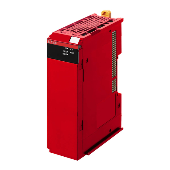
- Page 67 2 Specifications Safety CPU Unit NX-SL3300 Unit name Safety CPU Unit Model NX-SL3300 Maximum number of safety I/O points 256 points Program capacity 512 KB Number of safety master connections I/O refreshing method Free-Run refreshing External connection terminals None FS indicator, VALID indicator, DEBUG indicator, TS indicator, and RUN indicator Indicators...
- Page 68 Rated input voltage This is the rated input voltage of the Unit. OMRON Special Safety Input This tells whether the Unit supports the connection of OMRON Special Devices Safety Input Devices (D40A Non-contact Door Switches, E3FS Single Beam Safety Sensors, etc.).
-
Page 69: Safety Input Units
Number of test output points 2 points Internal I/O common PNP (sinking inputs) Rated input voltage 24 VDC (20.4 to 28.8 VDC) OMRON Special Safety Input Can be connected. Devices Number of safety slave con- nections I/O refreshing method Free-Run refreshing... - Page 70 2 Specifications T0 and T1 Terminal block Circuit layout Si0 to Si3 I/O power supply + I/O power supply + Left-side NX Right-side NX bus connector bus connector I/O power supply − I/O power supply − Si0 to Si3: Safety input terminals T0 and T1: Test output terminals NX-SIH400 Safety...
- Page 71 Number of test output points 2 points Internal I/O common PNP (sinking inputs) Rated input voltage 24 VDC (20.4 to 28.8 VDC) OMRON Special Safety Input Cannot be connected. Devices Number of safety slave con- nections I/O refreshing method Free-Run refreshing...
- Page 72 2 Specifications Si0 to Si7: Safety input terminals T0 and T1: Test output terminals NX-SID800 Safety Input Unit Safety switch Terminal connection diagram Refer to 3-3-1 Safety Input Functions on page 3-11 for details. Installation orientation: 6 possible orientations Installation orientation and Restrictions: Maximum ambient temperature is 50°C for any orientation restrictions other than upright installation.
-
Page 73: Safety Output Units
2 Specifications 2-2-4 Safety Output Units Datasheet Items for Safety Output Unit The following table gives the meaning of the datasheet items for the Safety Output Units. Item Specification Unit name This is the name of the Unit. Model This is the model number of the Unit. Number of safety output points This is the number of safety output points on the Unit. - Page 74 2 Specifications Safety Output Units NX-SOH200 Unit name Safety Output Unit Model NX-SOH200 Number of safety output points 2 points Internal I/O common PNP (sourcing outputs) 2.0 A/point 4.0 A/Unit at 40°C Maximum load current 2.5 A/Unit at 55°C The maximum load current depends on the installation orientation and ambient temperature.
- Page 75 2 Specifications So0 and So1: Safety output terminals IOG: I/O power supply 0 V NX-SOH200 Safety Output Unit Terminal connection diagram Refer to 3-3-2 Safety Output Functions on page 3-35 for details. Installation orientation: 6 possible orientations Restrictions: For upright installation, the ambient temperature is restricted as shown below according to the total Unit load current.
- Page 76 2 Specifications NX-SOD400 Unit name Safety Output Unit Model NX-SOD400 Number of safety output 4 points points Internal I/O common PNP (sourcing outputs) Maximum load current 0.5 A/point and 2.0 A/Unit Rated voltage 24 VDC (20.4 to 28.8 VDC) Number of safety slave con- nections I/O refreshing method...
- Page 77 2 Specifications So0 to So3: Safety output terminals IOG: I/O power supply 0 V NX-SOD400 Safety Output Unit Terminal connection diagram Refer to 3-3-2 Safety Output Functions on page 3-35 for details. Installation orientation: 6 possible orientations Installation orientation and restrictions Restrictions: None Protective functions...
-
Page 78: Pfh Values
PFH Values This section gives the PFH values of the NX-series Safety CPU Unit and the Safety I/O Units. Precautions for Correct Use Go to the following URL for the most recent PFH values: http://www.ia.omron.com/support/sistemalibrary/index.html. 2-3-1 Safety CPU Unit Model NX-SL3300 3.1E-10... -
Page 79: Part Names And Functions
Part Names and Functions This section gives the names of the parts of the Safety CPU Unit and Safety I/O Units and describes their functions. 3-1 Safety CPU Unit ..........3-2 3-1-1 Parts and Names . -
Page 80: Safety Cpu Unit
Letter Name Function Marker attachment The locations where markers are attached. The markers made by OMRON locations are installed for the factory setting. Commercially available markers can also be installed. For details, refer to 5-1-2 Attaching Markers on page 5-4. -
Page 81: Indicators
3 Part Names and Functions 3-1-2 Indicators The Safety CPU Unit has indicators that show the current operating status and communications status. WARNING Do not use the status of the indicators on the NX-series Safety Control Units for safety opera- tions. - Page 82 3 Part Names and Functions FS Indicator The FS indicator shows the safety communications status and safety function status of the Safety CPU Unit. The following table lists the possible states for this indicator and what they mean. Color Status Meaning Green Lit.
- Page 83 3 Part Names and Functions VALID Indicator The VALID indicator shows whether safety validation has been performed. Color Status Meaning Yellow Lit. Safety application data from the execution of the safety validation is stored in the non-volatile memory. Not lit. Safety application data from the execution of the safety validation is not stored in the non-volatile memory, or a fatal fault has occurred.
-
Page 84: Safety I/O Units
Marker attachment The locations where markers are attached. The markers made by locations OMRON are installed for the factory setting. Commercially available mark- ers can also be installed. For details, refer to 5-1-2 Attaching Markers on page 5-4. NX bus connector This is the NX-series bus connector. - Page 85 3 Part Names and Functions Terminal Blocks There are two types of Screwless Clamping Terminal Blocks: NX-TB2 and NX-TB1. The following models of Terminal Blocks can be mounted to Safety I/O Units. NX-TB2 Sixteen-terminal Block Eight-terminal Block NX-TB1 Eight-terminal Block Sixteen-terminal Block Letter Name...
- Page 86 3 Part Names and Functions Letter Name Function Terminal holes The wires are inserted into these holes. Terminal Blocks for Safety I/O Units come in two types depending on the number of terminals that can be used. There are 8-terminal and 16-terminal Terminal Blocks. You can use only one of the two types of terminal blocks given above with a Unit that has a screwless clamping terminal block.
-
Page 87: Indicators
3 Part Names and Functions 3-2-2 Indicators A Safety I/O Unit has indicators that give the status of the Unit, communications, and the safety I/O ter- minals. WARNING Do not use the status of the indicators on the NX-series Safety Control Units for safety opera- tions. - Page 88 3 Part Names and Functions FS Indicator The FS indicator shows the safety communications status and safety function status of the Safety I/O Unit. The following table lists the possible states for this indicator and what they mean. Color Status Meaning Green Lit.
-
Page 89: Safety I/O Functions
• Semiconductor Output for Dual Channel Equivalent • Semiconductor Output for Dual Channel Comple- mentary The following OMRON Special Safety Input Devices can be connected directly without a special con- troller (This applies only to the NX-SIH400.) 3 - 11... - Page 90 Door Switches Conforms to PLe and Safety Category 4. D40A Conforms to PLd and Safety Category 3. OMRON Safety Mats Conforms to PLd and Safety Category 3. OMRON Safety Edges SGE (4-wire connection) * Conforms to PLd and Safety Category 3.
- Page 91 3 Part Names and Functions Setting Up Safety Functions You can easily set the safety functions of the safety input terminals from the Sysmac Studio by selecting the types of external devices that are connected. Refer to 3-3 Safety I/O Functions on page 3-11 for details.
- Page 92 3 Part Names and Functions Connecting Input Devices This section describes the connection methods for input devices. Devices with Mechanical Contacts A device with mechanical contacts, such as an emergency stop pushbutton or safety limit switch, is used with the safety input terminal (Si) and test output terminal (To). •...
- Page 93 3 Part Names and Functions • Dual-channel Input When I/O Short Detection between Lines Is Not Required NX-SI Example of Sysmac Studio Settings 3 - 15 NX-series Safety Control Unit User’s Manual (Z930)
- Page 94 3 Part Names and Functions • Dual-channel Input When I/O Short Detection between Lines Is Required NX-SI Example of Sysmac Studio Settings Precautions for Correct Use • Configure dual-channel inputs with safety input terminals on the same Unit. It is not always possible to detect short circuits between safety input terminals on different Units.
- Page 95 3 Part Names and Functions Devices with Semiconductor Outputs The signal from a device with a semiconductor output, such as a light curtain, is input to a safety input terminal (Si). Safety Light Curtain 24 VDC Additional I/O Power Supply Unit or Communications Coupler Unit NX-SI NX bus connection...
- Page 96 30 µs max. Check the specifications of the connected device for the maximum cable length. E3ZS/E3FS Single-beam Safety Sensors An OMRON E3ZS/E3FS Single-beam Safety Sensor is connected as shown in the following figure. Single-beam Safety Sensors 24 VDC Communications Coupler Unit or...
- Page 97 3 Part Names and Functions Precautions for Correct Use • The maximum number of connections per Unit is as follows: NX-SIH400: 4 • You can branch the connections to up to four Single-beam Safety Sensors for each Test Out- put. Single-beam Single-beam Single-beam...
- Page 98 3 Part Names and Functions D40A/D40Z Non-contact Door Switches The non-contact door switch output (black line) from the OMRON D40A or D40Z Non-contact Door Switch is input to a safety input terminal. This is a one-line signal. When connecting it, branch it as shown at Si0 and Si1 in the following figure.
- Page 99 3 Part Names and Functions Precautions for Correct Use • The maximum number of connections per Unit is as follows: NX-SIH400: 20 (10 connected in series × 2 series) • You can connect up to 10 Non-contact Door Switches to each test output terminal. •...
- Page 100 3 Part Names and Functions UM Safety Mats OMRON UM Safety Mats are connected as shown in the following figure. n = 12 max. NX-SIH400 Safety Mats n + 1 Example of Sysmac Studio Settings Refer to Precaution for Conformance to ISO 13856-1:2013 on page 4-3 for a precaution on confor- mance to ISO 13856-1:2013.
- Page 101 3 Part Names and Functions Precautions for Correct Use • The maximum number of connections per Unit is as follows: NX-SIH400: 12 (12 connected in series × 1 series) • You can connect up to 12 Safety Mats to the two test output terminals. •...
- Page 102 3 Part Names and Functions SGE Safety Edges OMRON SGE Safety Edges are connected as shown in the following figure. n = 5 max. NX-SIH400 Safety Edges n + 1 Example of Sysmac Studio Settings 3 - 24 NX-series Safety Control Unit User’s Manual (Z930)
- Page 103 3 Part Names and Functions Precautions for Correct Use • The maximum number of connections per Unit is as follows: NX-SIH400: 5 (5 connected in series × 1 series) • You can connect up to five Safety Edges to the two test output terminals. •...
- Page 104 3 Part Names and Functions Types of Safety Input Functions The types of safety input functions that are performed by the Safety Input Unit is shown below. For the safety input functions, the safety signals that are input to the safety input terminals are evalu- ated and safety input data that can be used in the safety program is created.
- Page 105 An OMRON D40A or D40Z Non-contact Door Switch is connected. Test signals for the D40A or D40Z will be output. Safety Mat/Safety An OMRON UM Safety Mat or SGE Safety Edge (4-wire) is connected. A test signal for Edge Safety Mat/Safety Edge diagnosis is output.
- Page 106 3 Part Names and Functions Dual Channel Evaluation Safety input terminals can be used as dual channels (one pair). The dual channel evaluation evaluates the data for two inputs to check for discrepancy. • Single Channel Safety CPU Unit Safety Input Unit Safety input data Safety program Test pulse evaluation...
- Page 107 3 Part Names and Functions Input signal on the Safety input data Single/Dual safety input terminals Meaning of status Si (x) Si (x) Single Channel Inactive (OFF) Active (ON) • Relationship between Input Signals to Safety Input Terminals and Safety Input Data for Dual-channel Inputs Input signals on the Safety input data...
- Page 108 3 Part Names and Functions • Operation for Single Channel: Test Pulse Evaluation Error for Stuck-at-high Error Safety input terminal Error Cause of detected. error removed. Safety input data I/O indicator (yellow) I/O indicator (red) *1. This is the time that the error status (control data, status data, and indicator status) is held (1 s min.). •...
- Page 109 3 Part Names and Functions • Operation for Dual-channel Equivalent Inputs: Discrepancy Error Safety input terminal 0 Safety input terminal 1 Safety input data 0 before dual evaluation Safety input data 1 before dual evaluation Discrepancy time Safety input data 0 I/O indicator (yellow) 0 I/O indicator (yellow) 1 I/O indicator (red) 0...
- Page 110 3 Part Names and Functions Setting Error detection Contact with pos- Short circuits in Single/Dual Test pulse itive side of Disconnection Ground fault input wiring power line Detectable when Detectable when Detectable. Dual Channel Without Test Pulse Detectable when Complementary input turns ON or input turns ON or input turns ON or...
- Page 111 3 Part Names and Functions Precautions for Correct Use If an OFF delay is used, the OFF delay time affects the safety reaction time. Add the OFF delay time to the safety reaction time. (Refer to 4-1 Safety Reaction Times on page 4-2.) ...
- Page 112 3 Part Names and Functions Operation with Both an ON Delay and OFF Delay You can filter out ON pulses for the width that is set with the ON delay time and filter out OFF pulses for the width that is set with the OFF delay time. Safety input terminal Internal timer for ON delay...
-
Page 113: Safety Output Functions
3 Part Names and Functions 3-3-2 Safety Output Functions Connectable Output Devices The Safety Output Unit diagnoses the connected external devices through the safety output terminals. The general-purpose safety output devices that can be connected to the safety output terminals of a Safety Output Unit are listed in the following table. - Page 114 3 Part Names and Functions Use the wiring that is shown in the following figure to prevent a floating condition for the IOG of the Safety Output Unit even if the IOG line is broken. NX-ECC I/O power supply (24 VDC) NX-SO Load Connecting Output Devices...
- Page 115 3 Part Names and Functions Example of Sysmac Studio Settings Precautions for Correct Use • The line length from the safety output terminals to the output devices (L1, L2, L3, and L4) is 100 m max. for each line. • The total length of cable that is connected to one test output must be as described in 3-3-1 Safety Input Functions on page 3-11.
- Page 116 3 Part Names and Functions Servo Drive OMRON R88D-K Servo Drives are connected as shown in the following figure. NX-SO R88D-K NX-SI SF1+ EDM+ SF1- SF2+ EDM- SF2- SF1+ EDM+ SF1- SF2+ EDM- SF2- SF1+ EDM+ SF1- SF2+ EDM-...
- Page 117 3 Part Names and Functions Example of Sysmac Studio Settings Precautions for Correct Use • If you directly connect more than one EDM terminal to one safety input terminal, the voltage at the safety input terminal will be reduced proportionately to the number of connections. When determining the number of direct connections, consider the voltage drop between the EDM terminals in the design.
- Page 118 3 Part Names and Functions • If you branch connections to more than one SF terminal from one safety output terminal, the load current at the safety output terminal will be increased proportionately to the number of connections. When determining the number of branch connections, consider the input cur- rent to the SF terminals in the design.
- Page 119 3 Part Names and Functions Inverters OMRON 3G3MX2 Inverters are connected as shown in the following figure. NX-SO Inverter 30 m ≤ 30 m ≤ 30 m ≤ NX-SI 30 m ≤ 30 m ≤ + ... + L 100 m ≤...
- Page 120 3 Part Names and Functions Precautions for Correct Use • The number of connections per Unit is as follows: When NX-SOD400 and NX-SI are used: 2 (1 connected in series × 2 series) When NX-SOH200 and NX-SI are used: 1 (1 connected in series × 1 series) •...
- Page 121 3 Part Names and Functions Types of Safety Output Functions The types of safety output functions that are performed by the Safety Output Unit is shown below. The safety output functions diagnose the outputs to the safety output terminals and the external device wir- ing based on the safety output data from the safety program.
- Page 122 3 Part Names and Functions Test Pulse Evaluation The test pulse evaluation outputs a test pulse with a specific period on the 24-VDC power line from a safety output terminal to detect errors in wiring to the externally connected device. This evaluation is achieved through the Test Pulse Diagnosis parameter.
- Page 123 3 Part Names and Functions Single/Dual Set the evaluation method to use with the safety output terminals. Setting Description Single Channel The safety output terminals are used as independent safety output terminals. Dual Channel Equivalent The pair of safety output terminals are used as dual-channel outputs.
- Page 124 3 Part Names and Functions • Operation for Single Channel: Test Pulse Evaluation Error by Stuck-at-high Error Safety output data Safety output command value Safety output terminal Cause removed. Error detected. I/O indicator (yellow) I/O indicator (red) *1. This is the time that the error status (control data, status data, and indicator status) is held (1 s min.). •...
- Page 125 3 Part Names and Functions • Operation for Dual-channel Equivalent Outputs: Test Pulse Evaluation Error Safety output data Safety output command value Safety output terminal 0 Error Cause of error detected. removed. Safety output terminal 1 I/O indicator (yellow) 0 I/O indicator (yellow) 1 I/O indicator (red) 0 I/O indicator (red) 1...
- Page 126 3 Part Names and Functions Safety Output Terminal Short Detection The safety output terminal short detection prevents the internal circuits of the safety output terminals from being destroyed if an overcurrent flows due to a ground fault or other cause. If an overcurrent is detected, the safety output terminal is turned OFF.
-
Page 127: Calculating Safety Reaction Times
Calculating Safety Reaction Times This section describes how to calculate safety reaction times for Safety Control Units. 4-1 Safety Reaction Times ......... . 4-2 4-1-1 Safety Reaction Times . -
Page 128: Safety Reaction Times
OFF. The value is defined for each sensor or switch. response time The following values apply when an OMRON Special Safety Input Device is connected to a Safety Input Unit. E3ZS/E3FS Single-beam Safety Sensors: 14 ms D40A Non-contact Door Switches: 6 ms + 0.4 ms x No. of linked Switches... - Page 129 4 Calculating Safety Reaction Times Time element Description Safety I/O Calculate the sum of the following configuration elements. This is the time from when the safety refresh time input terminal changes until the change goes through the Safety CPU Unit and the safety output terminal turns OFF.
-
Page 130: Verifying Safety Reaction Times
4 Calculating Safety Reaction Times 4-1-3 Verifying Safety Reaction Times Verify the calculated safety reaction times for all safety chains to confirm that they satisfy the required specifications. If a calculated safety reaction time exceeds the required specifications, consider the following mea- sures and correct the software or hardware design. -
Page 131: Safety Task
4 Calculating Safety Reaction Times Safety Task This section describes the safety task of the Safety CPU Unit. The safety task period of the Safety CPU Unit affects the safety reaction times. 4-2-1 Safety Task The safety task is used to assign an execution condition to a series of processes, such as for data exchange with Safety I/O Units and safety program execution. -
Page 132: Calculating The Minimum Safety Task Period
4 Calculating Safety Reaction Times 4-2-3 Calculating the Minimum Safety Task Period This section describes how to find the minimum safety task period. Safety Control Systems on EtherCAT Networks The minimum safety task period depends on the communications setup of the Slave Terminal. ... -
Page 133: Setting The Safety Task Period
4 Calculating Safety Reaction Times 4-2-4 Setting the Safety Task Period This section describes how to find an approximation of the value to set for the safety task period. Use the following formula to find the safety task period. Safety task period = Minimum safety task period + Expansion communications monitoring time If the calculated value exceeds 100 ms, set the safety task period to 100 ms. - Page 134 4 Calculating Safety Reaction Times Additional Information We recommend that you set the safety task period with plenty of leeway to allow for the possi- bility of expanding the safety control system or safety programs in the future. 4 - 8 NX-series Safety Control Unit User’s Manual (Z930)
-
Page 135: Fsoe Watchdog Timers
4 Calculating Safety Reaction Times FSoE Watchdog Timers This section describes the FSoE watchdog timers. 4-3-1 FSoE Watchdog Timers An FSoE watchdog timer is used for timeouts in safety process data between the Safety CPU Unit and a Safety I/O Unit. The FSoE watchdog timers affect the safety reaction times. -
Page 136: Settings For Fsoe Watchdog Timers
4 Calculating Safety Reaction Times 4-3-3 Settings for FSoE Watchdog Timers This section describes how to find the set values for the FSoE watchdog timers. The set value for an FSoE watchdog timer is different from the set value of the safety task period. ... -
Page 137: Changing Fsoe Watchdog Timers
4 Calculating Safety Reaction Times 4-3-4 Changing FSoE Watchdog Timers Use the following procedure to change an FSoE watchdog timer. In the Multiview Explorer, select the Safety CPU Unit in the Controller Selection Box. Double-click Safety I/O under Configurations and Setup − Communications − Safety. The following Safety I/O Unit Setting Tab Page is displayed. - Page 138 4 Calculating Safety Reaction Times 4 - 12 NX-series Safety Control Unit User’s Manual (Z930)
- Page 139 Installation and Wiring This section describes how to install and wire the Safety Control Units. 5-1 Installing Units ..........5-2 5-1-1 Installing NX Units .
-
Page 140: Installing Units
5 Installation and Wiring Installing Units The NX-series Safety Control Units are installed in the same way as the NX Units. This section describes how to install and remove NX Units and how to attach markers. Refer to the user's manual of the Communications Coupler Unit for information on preparations of installation and installation in a control panel. - Page 141 5 Installation and Wiring Precautions for Correct Use • When you handle an NX Unit, be careful not to touch or bump the pins in the NX bus connec- tor. • When you handle an NX Unit, be careful not to apply stress to the pins in the NX bus connec- tor.
-
Page 142: Attaching Markers
You can attach markers to the NX Units and to the terminal blocks to identify them. The plastic markers made by OMRON are installed for the factory setting. The ID information can be written on them. Com- mercially available markers can also be installed. Replace the markers made by OMRON if you use commercially available markers now. -
Page 143: Removing Units
5 Installation and Wiring 5-1-3 Removing Units Precautions for Safe Use Always turn OFF the Unit power supply and I/O power supply before removing any NX Unit. Use a flat-blade screwdriver or similar tool to pull up the DIN Track mounting hook on the NX Unit to remove. -
Page 144: Installation Orientation
5 Installation and Wiring 5-1-4 Installation Orientation The Slave Terminal can be installed in any of the following six orientations. (A) is the upright installation orientation and (B) to (F) are installation orientations other than upright. Down However, there are restrictions on the installation orientation and restrictions to the specifications that can result from the Communications Coupler Units and NX Units that are used. -
Page 145: Wiring The Power Supply To The Slave Terminal
5 Installation and Wiring Wiring the Power Supply to the Slave Terminal Power is supplied to the Safety Control Units as described in the following table. 5-2-1 Power Supply Types There are the following two types of power supplies that supply power to the Slave Terminal. Power supply type Description Unit power supply... -
Page 146: Calculating The Total Current Consumption From The I/O Power Supply
5 Installation and Wiring Example wiring diagrams are provided in the following figures for the different types of power supplies. NX Unit Communications Additional NX Unit NX Unit power supply NX Unit Coupler Unit power supply Power Supply Unit Unit power supply terminals Internal power supply circuits... -
Page 147: Nx-Series Power Supply-Related Units
For the details on the NX-series power supply-related Units, refer to the NX-series System Units User’s Manual (Cat. No. W523). For information on the most recent lineup of NX Units, refer to NX-series cat- alogs or OMRON websites, or ask your OMRON representative. Name... - Page 148 5 Installation and Wiring Name Function Additional I/O This NX Unit provides additional I/O power supply. Power Supply Unit Use this NX Unit in the following cases. (a) When the I/O power supply capacity is insufficient • When the total current consumption for the I/O power supply exceeds the maximum I/O power supply current of the EtherCAT Coupler Unit •...
- Page 149 5 Installation and Wiring Name Function I/O Power Supply This Unit is used when there are not enough I/O power supply terminals for the external Connection Units devices that are connected to NX Units such as Safety I/O Units and Analog I/O Units. The I/O power supply is not separated The I/O power supply is not separated at the I/O Power Supply Connection Units.
-
Page 150: Wiring The Terminals
5 Installation and Wiring Wiring the Terminals This section describes how to wire the terminals on the Safety I/O Units. WARNING Make sure that the voltages and currents that are input to the NX Units and Slave Terminals are within the specified ranges. Inputting voltages or currents that are outside of the specified ranges may cause accidents or fire. - Page 151 5 Installation and Wiring Using Ferrules If you use ferrules, attach them to twisted wires. Observe the application instructions for your ferrules for the wire stripping length when attaching fer- rules. Precautions for Correct Use Always use plated one-pin ferrules. Do not use unplated ferrules or two-pin ferrules. The applicable ferrules, wires, and crimping tools are listed in the following table.
- Page 152 5 Installation and Wiring Using Twisted or Solid Wires If you use the twisted wires or the solid wires, use the following table to determine the correct wire specifications. Terminals Wire type Conductor Classifica- Current Twisted wires Solid wire Wire size length (strip- ping length)
- Page 153 5 Installation and Wiring Securing Wires It is necessary to secure wires to the screwless clamping terminal block depending on the wire types that are used or the current flows on the wires. The following table gives the necessity for securing wires. Terminals Wire type Classifica-...
- Page 154 5 Installation and Wiring Bundle the wires with a cable tie and secure them to the screwless clamping terminal block. Secure wires within the range of 30 mm from the screwless clamping terminal block. 5 - 16 NX-series Safety Control Unit User’s Manual (Z930)
- Page 155 5 Installation and Wiring Connecting/Removing Wires This section describes how to connect and remove wires. Terminal Block Parts and Names Release hole Terminal hole Required Tools Use a flat-blade screwdriver to connect and remove wires. Use the following flat-blade screwdriver. Side View Front View 8°...
- Page 156 5 Installation and Wiring Connecting Twisted Wires/Solid Wires Use the following procedure to connect the twisted wires or solid wires to the terminal block. Press the flat-blade screwdriver diagonally into the release hole. Press at an angle of 10° to 15°. If you press in the screwdriver correctly, you will feel the spring in the release hole.
- Page 157 5 Installation and Wiring Precautions for Correct Use Do not press the flat-blade screwdriver straight into the release hole. Doing so may break the terminal block. • When you insert a flat-blade screwdriver into a release hole, press it down with a force of 30 N or less.
- Page 158 5 Installation and Wiring Leave the flat-blade screwdriver pressed into the release hole and pull out the wire. Wire Remove the flat-blade screwdriver from the release hole. Precautions for Safe Use • Do not press the flat-blade screwdriver straight into the release hole. Doing so may break the terminal block.
- Page 159 5 Installation and Wiring Removing a Terminal Block Press the lock lever on the terminal block and pull out the top of the terminal block to remove it. Lock lever Terminal block Attaching a Terminal Block Mount the terminal block hook on the guide at the bottom of the NX Unit, lift up the terminal block, and press in on the top of the terminal block until you hear it engage.
- Page 160 5 Installation and Wiring Preventing Incorrect Attachment of Terminal Blocks In order to prevent unintentionally installing the wrong terminal block, you can limit the combination of a Unit and a terminal block. Insert three Coding Pins (NX-AUX02) into three of the six incorrect attachment prevention holes on the Unit and on the terminal block.
- Page 161 1 through 6 in the figure below. As shown in the following table, there are 20 unique pin patterns that you can use. Unit Terminal Block Holes used by OMRON Holes used by OMRON Holes for incorrect Holes for incorrect...
- Page 162 Precautions for Correct Use • OMRON uses the holes other than No. 1 to 6 in the above figure. If you insert a Coding Pin into one of the holes used by OMRON on the terminal block side, it is impossible to mount the terminal block on a Unit.
-
Page 163: Checking Wiring
5 Installation and Wiring Unit 5-3-2 Checking Wiring You can display the I/O Map or Watch Tab Page on the Sysmac Studio to check the wiring. For Input Units, you can turn ON and OFF an input from the external device that is connected to the Unit you need to check and monitor the results. - Page 164 5 Installation and Wiring 5 - 26 NX-series Safety Control Unit User’s Manual (Z930)
- Page 165 System Configuration and Setup This section describes how to use the Sysmac Studio to configure and set up the safety control system. 6-1 Configuration and Setup Procedures ......6-2 6-2 Part Names and Functions of the Sysmac Studio Window .
-
Page 166: Configuration And Setup Procedures
6 System Configuration and Setup Configuration and Setup Procedures This section describes the procedures for using the Sysmac Studio to configure and set up the safety control system. Make the settings in the following order. 1. Slave Terminal Configuration and Settings 2. -
Page 167: Part Names And Functions Of The Sysmac Studio Window
6 System Configuration and Setup Part Names and Functions of the Sysmac Studio Window This section gives the names of the parts of the Sysmac Studio Window. Use this box to select the Safety CPU Unit or the NJ/NX-series CPU Unit. Controller Selection Box The tab page will change between the Safety CPU Unit Setup and Programming View and the NJ/NX-series CPU Unit Setup and Programming View. -
Page 168: Controller Configuration And Setup Of The Safety Control Units
6 System Configuration and Setup Controller Configuration and Setup of the Safety Control Units This section describes the Safety Control Unit configuration and setting procedures for EtherCAT Slave Terminals and EtherNet/IP Slave Terminals. EtherCAT Slave Terminal Configuration and Setting Procedures You configure and set up the EtherCAT network and EtherCAT Slave Terminals where the Safety Control Units are mounted as part of the Controller Configuration and Setup of the NJ/NX-series CPU Unit. -
Page 169: Procedures For Creating The Controller Configuration For Safety Control
6 System Configuration and Setup 6-3-1 Procedures for Creating the Controller Configuration for Safety Control Use the following procedure to create the Controller configuration for the Safety Control Units. EtherCAT Slave Terminal Configuration and Setting Procedures Use the following procedure to create the Controller configuration for the Safety Control Units on Ether- CAT Slave Terminals. - Page 170 6 System Configuration and Setup Or, perform step 5 for the EtherCAT Coupler Unit that was added to display the Slave Terminal Tab Page. Select Safety Digital Input Device or Safety Digital Output Device from the Groups List in the Toolbox.
- Page 171 6 System Configuration and Setup EtherNet/IP Slave Terminal Configuration and Setting Procedures Use the following procedure to create the Controller configuration for the Safety Control Units on Ether- Net/IP Slave Terminals. Start the Sysmac Studio. Select the EtherNet/IP Coupler Unit on the Slave Terminal and create a project file. Double-click NX-EIC202 under EtherNet/IP −...
-
Page 172: Setting And Viewing The Safety Control Unit Settings
6 System Configuration and Setup 6-3-2 Setting and Viewing the Safety Control Unit Settings Set or view the settings for the Safety CPU Unit and Safety I/O Units (hereinafter, “Safety Control Units”) as necessary. You can change the device names of registered Safety Control Units, and enable or disable individual Units as NX Units. -
Page 173: Procedure To Change The Model Of The Safety Cpu Unit
6 System Configuration and Setup 6-3-3 Procedure to Change the Model of the Safety CPU Unit After you create the Controller configuration, you can change the model or unit version of the Safety Control Unit without changing the saved settings information. Use the following procedure to change the Safety CPU Unit. -
Page 174: Setting Up The Safety Process Data Communications
6 System Configuration and Setup Setting Up the Safety Process Data Communications When you add a Safety Control Unit to the NX bus on the Slave Terminal Tab Page, the safety process data communications are set up automatically. Use the following procedure to view or change the settings for the safety process data communications. In the Multiview Explorer, select the Safety CPU Unit in the Controller Selection Box. - Page 175 6 System Configuration and Setup Item Editing Description WDT auto Possible. This setting specifies the setting method for the FSoE watchdog timer (WDT). setting Selected: The minimum value is set for the FSoE watchdog timer (WDT). Cleared: You can set the FSoE watchdog timer (WDT) to the desired value. *1.
-
Page 176: Setting The Safety Input And Output Functions
6 System Configuration and Setup Setting the Safety Input and Output Functions You set the safety input functions and safety output functions of the Safety I/O Unit when you assign input devices and output devices to the Safety I/O Unit with the Sysmac Studio. This section describes how to assign devices that are connected. - Page 177 6 System Configuration and Setup Select a device from the Toolbox to connect to the safety input terminal or safety output terminal of the Safety I/O Unit, and drag it to the desired I/O terminal. Drag & Drop Enter a comment. When you drag the device to connect to a terminal where it can be dropped, a + mark appears below the mouse cursor as shown below.
- Page 178 6 System Configuration and Setup When you complete the settings, the following is displayed. Change the settings and enter com- ments. Refer to 3-3-1 Safety Input Functions on page 3-11 and 3-3-2 Safety Output Functions on page 3-35 for the I/O devices that you can connect and the settings for each I/O device. Precautions for Correct Use If you select an input device that cannot be set for a Safety Input Unit, an error will occur and the frame around the input device will be displayed in red.
-
Page 179: Registering Device Variables
6 System Configuration and Setup Registering Device Variables Device variables are used to access data in slaves and Units. This data is accessed through a port that acts as an interface to an external device. This logical port is called an I/O port. To make the values of the I/O on the Safety I/O Units available in the safety program in the Safety CPU Unit, you must register device variables for the I/O ports on the Safety I/O Unit. - Page 180 6 System Configuration and Setup Additional Information If the I/O terminals on the Safety I/O Unit are set to Dual Channel Mode, the device variable can only be assigned to an even-numbered terminal. I/O Ports for Safety I/O Units That Are Displayed in the I/O Map of the Safety CPU Unit The I/O ports for Safety I/O Units that are displayed in the I/O Map of the Safety CPU Unit are described in this section.
- Page 181 6 System Configuration and Setup NX-SID800 Safety Input Unit Port Data type Name Description Default Si00 Logical Value SAFEBOOL R Si00 Logi- Gives the status of cal Value safety input terminal Si00. 0: OFF, 1: ON Si01 Logical Value SAFEBOOL R Si01 Logi- Gives the status of...
- Page 182 6 System Configuration and Setup NX-SOH200 Safety Output Unit Port Data type Name Description Default Safety Connection Status SAFEBOOL R Safety Con- This flag indicates nection Sta- when a safety connec- tion is active. Use it for an input to the Activate terminal on a safety FB or for safety connec- tion/disconnection...
- Page 183 6 System Configuration and Setup NX-SOD400 Safety Output Unit Port Data type Name Description Default Safety Connection Status SAFEBOOL R Safety Con- This flag indicates nection Sta- when a safety connec- tion is active. Use it for an input to the Activate terminal on a safety FB or for safety connec- tion/disconnection...
-
Page 184: Exposing Variables To Standard Controllers
6 System Configuration and Setup Exposing Variables to Standard Con- trollers This section describes how to control and monitor a Safety CPU Unit from a standard controller through standard process data communications. 6-7-1 Exposing Global Variables When you set global variables in the Safety CPU Unit for standard process data communications, the variables are exposed as I/O ports in the I/O Map of the Communications Coupler Unit. -
Page 185: Setting Exposed Variables
6 System Configuration and Setup *2. Calculating the Output Data Size Use the following formula to calculate the output data size. If the size of the exposed variables is an odd num- ber of bytes, add one byte to make it an even number of bytes. Formula: Output data size = Exposed output variable size + Data size of communications with Safety I/O Units Use the following formula to calculate the exposed output variable size. - Page 186 6 System Configuration and Setup Registering New Variables on the Exposed Variables Tab Page Use the following procedure to register variables on the Exposed Variables Tab Page when those vari- ables are not registered as global variables. The registered exposed variables are automatically regis- tered as global variables.
- Page 187 6 System Configuration and Setup Setting the Expose Column for Global Variables Register global variables with standard data types. Refer to 7-5-3 Registering Variables on page 7-38 for details on registering variables. Select the Expose Column for global variables, and then select Input or Output. The selected variable is registered in the exposed variable input table or output table.
- Page 188 6 System Configuration and Setup Right-click one or more global variables and select Copy from the menu. The selected global variables are copied. Press the Shift Key or Ctrl Key to select more than one global variable. Right-click in the Exposed Variables Tab Page and select Paste from the menu. The global variables are set as exposed variables.
- Page 189 6 System Configuration and Setup Selecting Global Variables on the Exposed Variables Tab Page Use the following procedure to select registered global variables on the Exposed Variables Tab Page and set them as exposed variables. Register global variables with standard data types. Refer to 7-5-3 Registering Variables on page 7-38 for details on registering variables.
-
Page 190: Safety Cpu Unit Status
6 System Configuration and Setup 6-7-3 Safety CPU Unit Status If you place a Safety CPU Unit on the NX bus of a Communications Coupler Unit, standard process data communications are performed automatically. Using an EtherCAT Coupler Unit The status of a Safety CPU Unit is displayed as I/O ports in the I/O Map of the NJ/NX-series CPU Unit. -
Page 191: I/O Refreshing Method
6 System Configuration and Setup 6-7-5 I/O Refreshing Method This section describes the I/O refreshing method of the Safety Control Units. I/O Refreshing Method Only Free-Run refreshing can be used for Safety Control Units. With Free-Run refreshing, the refresh cycle of the NX bus and the I/O refresh cycle of the NX Units operate asynchronously. The Safety CPU Unit reads inputs and refreshes outputs according to the safety task period. -
Page 192: Setting Standard Process Data Communications
6 System Configuration and Setup Setting Standard Process Data Com- munications This section describes procedures for using standard process data communications between a Safety CPU Unit and Standard I/O Units. 6-8-1 Using an EtherCAT Coupler Unit For standard process data communications between the Safety CPU Unit and Standard I/O Units, the standard controller exchanges the data between the Safety CPU Unit and Standard I/O Units. - Page 193 6 System Configuration and Setup Item Editing Description Data Type Not possible. The data type of the variable is displayed. Comment Not possible. The comment set for the exposed variable is set. Device Possible. Set the NX Unit to which the exposed variable is allocated. Linked Port Possible.
-
Page 194: Exporting/Importing Settings Data
6 System Configuration and Setup Exporting/Importing Settings Data This section describes how to reuse the settings data for the entire Slave Terminal in the Sysmac Studio or the safety application data in the Safety CPU Unit. You can export and import the data for the entire Slave Terminal or the safety application data in the Safety CPU Unit as a single file. - Page 195 6 System Configuration and Setup Right-click the target EtherCAT Coupler Unit and select Export Slave Settings from the menu. The Save File Dialog Box is displayed. Enter a file name, and then click the Save Button. An EtherCAT slave parameter file with an .ets extension is saved. To import a file, select the Unit above the point where you wish to add the slave on the Ether- CAT Tab Page, and then right-click and select Import Slave Settings and Insert New Slave from the menu.
-
Page 196: Exporting/Importing The Settings For All The Nx Units On A Slave Terminal
6 System Configuration and Setup Additional Information If you distribute multiple Safety Control Units on different EtherCAT Slave Terminals, you can use the following method to manage all of the safety control settings in one file. • Saving the Safety Application Data Place all of the Safety Control Units on one Slave Terminal and export the settings. - Page 197 6 System Configuration and Setup Right-click the Communications Coupler Unit and select Export All NX Unit Settings from the menu. The Export All NX Unit Settings Dialog Box is displayed. Enter a file name, and then click the Save Button. A configuration file for all the NX Units with an .nsfp extension is saved.
-
Page 198: Exporting/Importing Data For Individual Safety Cpu Units
6 System Configuration and Setup 6-9-3 Exporting/Importing Data for Individual Safety CPU Units You can export and import the safety application data for only the Safety CPU Unit as a single file (extension .nsf). The exported Safety CPU Unit settings file can be imported to reuse the safety application data for a Safety CPU Unit with the same settings. - Page 199 6 System Configuration and Setup Precautions for Correct Use • When you import the data to the Safety CPU Unit, first configure all of the Safety I/O Units. • If importing data results in two or more Safety CPU Units, an error will occur. Delete the Safety CPU Units that are not used.
- Page 200 6 System Configuration and Setup 6 - 36 NX-series Safety Control Unit User’s Manual (Z930)
-
Page 201: Programming
Programming This section describes variables, instructions, and other elements that are used to cre- ate safety programs. It also describes the programming operations that are used on the Sysmac Studio. 7-1 POUs (Program Organization Units) ......7-3 7-1-1 What Are POUs? . - Page 202 7 Programming 7-6 Monitoring Memory Usage ........7-67 7-7 Offline Debugging .
-
Page 203: Pous (Program Organization Units)
7 Programming POUs (Program Organization Units) The safety program that runs on a Safety CPU Unit is made from a combination of POUs (program organization units). This section describes the configuration and specifications of POUs. Refer to 7-5 Programming Operations on page 7-27 for the procedures to create POUs on the Sysmac Studio. -
Page 204: Overview Of The Three Types Of Pous
7 Programming 7-1-2 Overview of the Three Types of POUs Programs Executing Programs and Execution Conditions • You execute a safety task to execute the programs that are assigned to that safety task. • Programs are always executed. Notation •... -
Page 205: Differences Between Programs, Functions, And Function Blocks
7 Programming 7-1-3 Differences between Programs, Functions, and Function Blocks Programs Function blocks (FBs) Functions (FUNs) User-defined only Instructions or user-defined Instructions only Type (User-defined functions not supported.) Executed upon execution Called from a program or Called from a program or Execution method of the safety task. -
Page 206: Details On Function Blocks
7 Programming Program Execution Conditions Programs are executed when the safety task they are assigned to is executed. Order of Execution You can set the order of execution of all programs in a safety task. You set this order in the Program Assignment Settings Display of the Task Settings Tab Page on the Safety CPU Unit Setup and Programming View on the Sysmac Studio. - Page 207 7 Programming • Function Block Settings When you create an instance of a function block definition, make the following settings. Settings of a function block instance in a program Instance name Function block name Local variable table Output parameters Input parameters Output variables Input variables Internal variables...
- Page 208 7 Programming Variable Designations for Function Blocks Instance name Function block definition name Value is assigned. Value is assigned. or instruction name Input parameter Output parameter Input variables Internal variables Output variables The specifications for variables in function blocks are given below. Variables Specification Number...
- Page 209 7 Programming Function Block Definitions and Instances A function block consists of a function block definition that is made in advance and instances that are used in the actual programs. All instances of a function block are based on the function block definition. A function block definition consists of an algorithm and a local variable table.
-
Page 210: Details On Functions
7 Programming Accessing Variables in a Function Block from Outside the Function Block You can access the input and output variables of a function block from outside the function block. Vari- ables are written as follows: InstanceName.VariableName Example: To Access Output Variable B of Function Block Instance FB1_Instance FB1_Instance.B FB1_Instance FB1_Instance.B... -
Page 211: Instructions
7-1-7 Instructions Instructions are the smallest unit of the processing elements that are provided by OMRON for use in POU algorithms. There are FB instructions and FUN instructions. Programs and user-defined function blocks consist of a combination of these instructions. -
Page 212: Variables
7 Programming Variables In the Safety CPU Unit, variables are used to exchange I/O information with external devices, to per- form data calculations, and to perform other processes. This section describes variable designations in detail. 7-2-1 Variables Variables store I/O data for exchange with external devices or temporary data that is used for internal POU processing. - Page 213 7 Programming Local Variables A local variable can be read and written only inside the POU (program or function block) in which it is defined. “Local variables” is the generic term for internal variables, input variables, output variables, and external variables. ...
-
Page 214: Attributes Of Variables
7 Programming 7-2-4 Attributes of Variables You can set the following attributes for variables. Variable Attributes According to Variable Type Attributes of Variables Attribute Description Specification Default The variable name is used to iden- UTF-8 format, 127 bytes Name Variable Name tify the variable. -
Page 215: Data Types
7 Programming 7-2-5 Data Types The Data Type attribute defines the type of data and range of data that is expressed by a variable. The amount of memory that is allocated when you declare a variable depends on the data type of that vari- able. - Page 216 7 Programming Basic Data Types The basic data types are given below. Type Data type Safety/standard data type Range of values Notation BOOL Standard data type FALSE or TRUE bool#0 or bool#1 Boolean Safety data type SAFEBOOL FALSE or TRUE *1*2 Standard data type byte#16#00 to...
-
Page 217: Variable Attributes Other Than Data Type
7 Programming 7-2-6 Variable Attributes Other Than Data Type This section describes the variable attributes other than the Data Type. Variable Name Attribute The variable name is used to identify the variable. Each variable in a POU must have a unique name. However, you can declare local variables with the same variable name in different POUs. -
Page 218: Function Block Instances
7 Programming 7-2-7 Function Block Instances Function block instances are added to and displayed in the local variable table or the global variable table as data types. Additional Information A function block instance is treated as a local variable of the program in which the instance is created. - Page 219 7 Programming Reserved Words An error is detected during the program check for the following names. • Use of the same name as any of the instructions that are described in the NX-series Safety Control Unit Instructions Reference Manual (Cat. No. Z931). •...
-
Page 220: Constants (Literals)
7 Programming Constants (Literals) This section describes constants. 7-3-1 Constants The value of a variable changes depending on the data that is assigned to that variable. The value of a constant never changes. Unlike variables, constants are not stored in memory. You can use constants in the algorithm of a POU without the need to declare them. - Page 221 7 Programming Bit Strings Bit String Data Notation Example Remarks {data_type}#{base}#{numeric word#16#0064 • Data type: BYTE or WORD _value] • Base: 2, 8, 10, or 16 The normalizing processing omits the base of 10 and converts values entered as base of 8 to decimal num- bers.
-
Page 222: Programming Languages
7 Programming Programming Languages This section describes the programming languages in detail. Refer to 7-5 Programming Operations on page 7-27 to learn how to enter the programming languages on the Sysmac Studio. 7-4-1 Programming Languages The languages used to express the algorithms in a POU (program or function block) are called the pro- gramming languages. - Page 223 7 Programming Jump instruction Instructions or user-defined function blocks Networks Input parameters Exception RETURN Return instruction Jump label Exception: Output parameters The networks shown above include a Jump instruction that changes the top-to-bottom flow of execution between networks, a label that shows the network to jump to, and a Return instruction. Refer to Execution Order of Safety Programs Written in the FBD Language on page 7-24 and Execu- tion Control on page 7-24 later in this manual, and also to the NX-series Safety Control Unit Instructions Reference Manual (Cat.
- Page 224 7 Programming Execution Order of Safety Programs Written in the FBD Language In POUs that are written in the FBD language, networks are executed in order from top to bottom. Pro- cessing ends when the network at the very bottom of the program is executed. Elements in the same network are executed from top to bottom for FUN and FB inputs and left to right for blocks that are con- nected in series.
- Page 225 7 Programming Connecting Instructions or User-defined Function Blocks Correct Connection Configurations You can connect a parameter to an instruction or a user-defined function block with a connecting line. Var1 Var2 You can connect a pair of instructions or a pair of user-defined function blocks with a connecting line. You can also connect more than one instruction or user-defined function block to another instruction or user-defined function block.
- Page 226 7 Programming Incorrect Connection Configurations You cannot connect more than one instruction or user-defined function block to the right of another instruction or user-defined function block. In this case, you must pass the signal to a variable as shown in the following figure. Var1 Var1 You cannot route a connecting line from the output to the input.
-
Page 227: Programming Operations
7 Programming Programming Operations This section describes the procedures on the Sysmac Studio that you use to create safety programs for the Safety CPU Unit. 7-5-1 Programming Layer on the Sysmac Studio You use the Programming Layer with the Controller set to the Safety CPU Unit on the Sysmac Studio as shown below to create safety programs for the Safety CPU Unit. - Page 228 7 Programming The structure of the Edit Pane is shown below. Variable table FBD editor CRC data Item Editing Description Variable table Possible. Displays the local variables. FBD editor Possible. Displays the FBD network. CRC data Not possible. Displays the CRC data of the POU. 7 - 28 NX-series Safety Control Unit User’s Manual (Z930)
-
Page 229: Registering Pous
7 Programming 7-5-2 Registering POUs This section shows how to register programs and function blocks. Registering Programs Registering New Programs − Right-click Programs under Programming − POUs and select Add Program from the menu. A new program is added under Programs. Double-click the program that was added. - Page 230 7 Programming Displaying Properties This section describes how to display program and function block properties. Right-click the registered program or function block and select Properties from the menu. The Properties Dialog Box is displayed. The following table describes the items in the Properties Dialog Box. Item Editing Description...
- Page 231 7 Programming Exporting Programs You can export a program to a file (extension .spg). You can import an exported program to reuse it in another project. Use the following procedure. Right-click a program displayed under Programming − POUs − Programs in the Multiview Explorer, and then select Export from the menu.
- Page 232 7 Programming Importing Programs You can import an exported program to reuse it in another project. WARNING Check during the import of the program that the CRC of the program is correct. Serious injury may possibly occur due to loss of required safety functions. Use the following procedure to import a program that was previously exported.
- Page 233 7 Programming A dialog box to check the CRC data is displayed. Check the CRC data, and click the OK Button. The program is imported and added to the project. Precautions for Correct Use After a function block is imported, the Safety CPU Unit will be in an unvalidated state. Always execute safety validation again.
- Page 234 7 Programming Exporting User-defined Function Blocks You can export a user-defined function block to a file (extension .sfb). You can import the exported user-defined function block to reuse it in another project. Use the following procedure. Right-click the user-defined function block under Programming - POUs - Function Blocks in the Multiview Explorer and select Export from the menu.
- Page 235 7 Programming Importing User-defined Function Blocks You can import the exported user-defined function block to reuse it in another project. WARNING Check during the import of the user defined function that the CRC of the imported func- tion block is correct. Serious injury may possibly occur due to loss of required safety functions.
- Page 236 7 Programming When a function block help file is imported, the following File Selection Dialog Box is displayed. If you select a help file (.pdf extension) with the same name as the imported function block, the specified file is copied to the save location for the user-defined help file. A dialog box to check the CRC data is displayed.
- Page 237 Prepare a help file with the same name as the function block (extension .pdf). Save the help file in the specified folder. The default folder is C:\OMRON\Data\Lib\Safety. Changing the Save Location for Help Files You can change the folder in which help files are saved.
-
Page 238: Registering Variables
7 Programming 7-5-3 Registering Variables This section describes how to register global variables and local variables. Creating Global Variables Opening the Global Variable Table Double-click Global Variables under Programming - Data in the Multiview Explorer. Or, right-click Global Variables under Programming − Data and select Edit from the menu. The global variable table is displayed. - Page 239 7 Programming Registering New Global Variables Press the Insert Key in the global variable table, or right-click in the global variable table and select Create New from the menu. Enter values for each item, and then press the Enter Key. The variable is registered.
- Page 240 7 Programming Editing Global Variables Click the cell to edit for the registered variable. You can use the autocompletion to enter a data type in the Data Type cells. When you enter the first letter (example: S), a list of data types that begin with that letter is displayed. Select a data type from the list.
- Page 241 7 Programming A copy of the variable is registered with “_Copy” added to the name of the variable that was copied on the next row. Precautions for Correct Use If you enter any invalid characters or out of range values, the cell is highlighted in pink. An error will occur when the program is built.
- Page 242 7 Programming Registering Local Variables Registration of local variables refers to the registration of variables that can be used only inside POUs (programs and function blocks). Local variables include internal variables, input variables, output variables, and external variables. Registering and Editing Local Variables Double-click a program under Programming −...
-
Page 243: Fbd Programming
7 Programming Additional Information The operating procedures for local variables are the same as the procedures used for global variables. Refer to 7-5-3 Registering Variables on page 7-38. 7-5-4 FBD Programming With the Safety CPU Unit, you use the FBD language to express algorithms that are inside the POUs (programs and function blocks). - Page 244 7 Programming Zooming In and Zooming Out of the FBD Editor Use the icons that are displayed in the toolbar to zoom in or zoom out of the FBD editor. Inserting FBD Networks Use one of the following procedures to insert an FBD network. Method 1: Right-click the FBD network and select Insert Network Above from the menu.
- Page 245 7 Programming Editing Comments for FBD Networks Use the following procedure to edit the comment for an FBD network. Method: Select the comment portion of the FBD network and edit it. Commenting Out FBD Networks and Restoring Them The following operation allows you to comment out an FBD network and then restore it. When a net- work is commented out, it is no longer executed.
- Page 246 7 Programming Procedure for Method 1 Drag a FUN or FB from the Toolbox to an I/O terminal on the FUN or FB in the FBD editor, or to a new network where the words Start here are displayed. Positions where you can drop the function block are indicated with gray rectangular or diamond-shape boxes.
- Page 247 7 Programming Precautions for Correct Use Not all of the FUNs and FBs that you can use are displayed in the Toolbox. To use a FUN or FB that is not shown in the Toolbox, use method 2. Additional Information With method 2, you can click the Input Assistant Button ( ) to the right of the FB name text box to display the Input Assistant Dialog Box.
- Page 248 7 Programming If you drop the SF_Antivalent FB on an input terminal, the FB is inserted before the input termi- nal. • If you select a FUN or FB (in this example, SF_Antivalent) from the right-click menu, the FUN or FB is inserted at the location shown below.
- Page 249 7 Programming Procedure for Method 1 Drag a FUN or FB from the Toolbox to the FB to replace. A Replace area is displayed. Drop the FUN or FB in the Replace area to replace the FUN or FB. ...
- Page 250 7 Programming • After the Input Parameter Is Added Changing the Output Terminals of a FUN or FB Use the following procedure to change the output terminals of a FUN or FB. Method: Right-click an output terminal on a FUN or FB on the FBD network and select Set Output Connection from the menu.
- Page 251 7 Programming Deleting Unused Parameters from a FUN or FB Use the following procedure to delete any unused parameters from a FUN or FB. Method: Right-click the FUN or FB on the FBD network and select Remove unused FB call parame- ters from the menu.
- Page 252 7 Programming Editing Function Block Instance Variables Use one of the following methods to edit existing function block instance variables. If you specify a variable name that does not exist in the local variable table, that variable will be regis- tered as a local variable.
- Page 253 7 Programming • After the Input Parameter Is Edited To delete an input parameter assignment, select the parameter and press the Delete Key. Additional Information • To create a new input variable, enter the variable name and press the Enter Key. The input parameter is registered, and it is also registered as a local variable in the local variable table.
- Page 254 7 Programming Changing Variable Registration Locations You can use the following option to enable the selection of the variable registration locations when you enter parameters. Procedure Select Option from the Tools Menu. The Options Dialog Box is displayed. Click Safety FBD Editor. The Auto Variable Registration Option is displayed.
- Page 255 7 Programming Assigning Output Parameters You can insert output variables at specified locations. Use one of the following procedures to assign an output parameter to an output variable of a FUN or FB. Method 1: Drag Assignment from General in the Toolbox to a terminal in the FBD editor, or to a new FBD network where the words Start here are displayed.
- Page 256 7 Programming The output parameter is inserted on a branch that is created before the output variable. Deleting Output Parameters Use the following procedure to delete output parameters. Method: Right-click the output parameter on the FBD network and select Delete from the menu. •...
- Page 257 7 Programming Editing Output Parameters Use one of the following procedures to edit output parameters. If you specify a variable name that does not exist in the local variable table, that variable will be regis- tered as a local variable. Method: Select the output variable on the FBD network and directly enter the variable name.
- Page 258 7 Programming Editing Jump Labels Use the following procedure to edit jump labels. Method: Select the jump label on the network and edit it. • The jump label becomes editable when you click it. After you finish editing, press the Enter Key. •...
- Page 259 7 Programming • After Jump Instruction Is Inserted Deleting Jump Instructions Use one of the following procedures to delete a Jump instruction. Method 1: Right-click the Jump instruction and select Delete from the menu. Method 2: Select the Jump instruction and press the Delete Key. •...
- Page 260 7 Programming Viewing the Locations of Variable Definitions You can view where variables are defined. Use the following procedure. Method: Right-click the variable and click Browse − Go To Definition from the menu. • The focus moves to the location where the variable is defined (local variable). Viewing the Locations of User-defined Function Block Definitions You can view where user-defined function blocks are defined.
-
Page 261: Building
7 Programming • Jumping to the Next Variable The display will jump to the next location where the selected variable is used in the POUs when you select Next Variable from the menu. • Jumping to the Previous Variable The display will jump to the previous location where the selected variable is used in the POUs when you select Previous Variable from the menu. - Page 262 7 Programming The following items are displayed in the Build Tab Page. If there is an error, double-click a line in the list to display the location of the error, and then cor- rect the error. Item Example Meaning Number of errors Displays the total number of errors.
-
Page 263: Searching And Replacing
7 Programming 7-5-6 Searching and Replacing You can search and replace strings in the data of a project. Scope of Searching and Replacing You can search for and replace text strings in the following items. Selected item Scope of searching and replacing All items (text strings) Variable names, variable comments, FBD network comments, jump labels, and Jump instructions. - Page 264 7 Programming Setting Items The setting items in the Search and Replace Pane are explained below. Item Description Search what • Enter a search string. • You can select from previous search strings in the list. Replace with • Enter the string to replace the search string with. •...
- Page 265 7 Programming Wildcards Character Meaning Description Example Zero or more characters Searches for a text string “new*” matches “newfile.txt”. that contains a variable text string. Any single character Searches for a text string “A?C” matches “ABC”, “AdC”, and “AzC”. with a variable character.
-
Page 266: Safety Task Settings
7 Programming 7-5-7 Safety Task Settings This section describes the procedures that are used to select the programs to execute in the safety task and the execution order of the selected programs. It also describes how to set the task period of the safety task. -
Page 267: Monitoring Memory Usage
7 Programming Monitoring Memory Usage You can display the memory usage in the safety control system and the safety network usage, such as the I/O data sizes. Precautions for Correct Use Check memory usage when there are no building errors. If there is a building error, the memory usage is not displayed correctly. - Page 268 7 Programming Item Displayed information Related parameters Program Memory Displays the memory usage of the • Number of Safety I/O Unit connections safety program. • Number of functions and function blocks in the safety program • Numbers of exposed variables, global vari- ables, and device variables •...
-
Page 269: Offline Debugging
7 Programming Offline Debugging Offline debugging allows you to debug a program when you are not connected online to a Safety CPU Unit. You can debug on a Simulator to check control program logic before transferring the project to the Safety CPU Unit. - Page 270 7 Programming Select Safety Simulation Pane from the View Menu. The Safety Simulation Pane is displayed below the Toolbox Pane on the right of the window. Click the Run Button in the Safety Simulation Pane. Or, select Run from the Simulation Menu. The following Connect to safety device Dialog Box is displayed.
- Page 271 7 Programming Click the OK Button. The following transfer confirmation dialog box is displayed. Click the Yes Button. The following device confirmation dialog box is displayed. Click the OK Button. Note You do not need to enter anything in the Password Box. After the Simulator is started and connected, the Online Indicator in status monitor is lit green.
-
Page 272: Monitoring
7 Programming To end the simulation, click the Close Button (×) in the Safety Simulation Pane. The values of variables return to their initial values. Pausing Use the following procedure to pause a simulation. The values of variables are retained. Program execution stops at the start of the program. -
Page 273: Feedback Setting
7 Programming Select the type of variables. The selected type of variables is displayed. The following types of variables can be selected: global variables, programs, and function blocks. Change the initial values of the variables. 7-7-5 Feedback Setting You can set input status that is linked to changes in output status, such as feedback inputs for safety relays. -
Page 274: Simple Automatic Test
7 Programming Precautions for Correct Use When you use the feedback settings on the Simulator, set MonitoringTime in the SF_EDM instruction to 300 ms min. Make sure to return the setting to the original value when you transfer the program to the phys- ical Safety CPU Unit. - Page 275 7 Programming The following Simple Automatic Test Tab Page is displayed. The setting areas of the Simple Automatic Test are configured as described in the following table. Item Name Function Simple Automatic Test The operation panel is used to make settings for and execute the Simple Auto- Operation Panel matic Test.
- Page 276 7 Programming Item Name Function Input Setting Area Set the variables of the input signals to use in the Simple Automatic Test. In addition to the variable name, set the reset types and input signal types of the input signals. Variable Set the names of the variables used as the input signals in the program.
- Page 277 7 Programming Setting Example A setting example for the Simple Automatic Test is provided in this section for the application example given in A-3-2 Safety Doors on page A-22. Application Overview from A-3-2 Safety Doors on page A-22. Safety category/PL Safety device Stop category Reset...
- Page 278 7 Programming • Feedback Settings Tab Page Execution Procedure for a Simple Automatic Test Use the following procedure to execute the Simple Automatic Test. Select Simulation - Simple Automatic Test from the menu. The Simple Automatic Test Tab Page is displayed. Set the test condition, input settings, output settings, and expected value settings.
- Page 279 7 Programming You can check the progress of the Simple Automatic Test in the following dialog box. The Simulator stops when the test is completed. Click the OK Button. 7 - 79 NX-series Safety Control Unit User’s Manual (Z930)
- Page 280 7 Programming The Simple Automatic Test Results Window is displayed when the test is completed. If the results show that the test has failed, correct the safety program or check the test settings. Precautions for Correct Use The Simple Automatic Test is provided as a simple means to check the output signal results for the input signals.
-
Page 281: Checking Operation And Actual Operation
Checking Operation and Actual Operation This section describes the procedures to perform before you can operate the Safety CPU Unit. It describes the operating modes of the Safety CPU Unit, checking operation in DEBUG mode, and the procedures to perform safety validation. 8-1 Procedures before Operation and Transferring the Required Data . - Page 282 8 Checking Operation and Actual Operation 8-9 Performing Safety Validation and Operation ..... . . 8-48 8-9-1 Performing Safety Validation ........8-48 8-9-2 Changing to RUN Mode .
- Page 283 8 Checking Operation and Actual Operation 8-10 Uploading Configuration Information and Safety Application Data ..8-52 8-10-1 Outline ............8-52 8-10-2 Uploading Data for a Connection to an NJ/NX-series CPU Unit .
-
Page 284: Procedures Before Operation And Transferring The Required Data
8 Checking Operation and Actual Operation Procedures before Operation and Transferring the Required Data This section describes the procedures to perform after you create the safety programs and are ready to operate the Safety CPU Unit. It also describes the data that you must transfer. 8-1-1 Commissioning Procedure After you write the safety programs, use the following procedure to start operating the Safety CPU Unit. - Page 285 8 Checking Operation and Actual Operation NJ/NX-series CPU Safety CPU Unit Unit Setup and Safety CPU Unit Setup and Programming View Setup and Programming View Programming View Steps 4 and 5 Steps 1 and 2 Step 3 Step 6 Step 7 Checking operation Performing safety validation Transferring the Slave...
-
Page 286: Data That You Must Transfer Before Operation And Data Transfer Procedures
8 Checking Operation and Actual Operation 8-1-2 Data That You Must Transfer before Operation and Data Transfer Procedures Before you change to RUN mode, you must transfer the Slave Terminal settings, including the Safety Control Unit settings, to the Safety CPU Unit. The settings and transfer procedures are given below. Transfer method Connection to USB Transfer... -
Page 287: Transferring The Configuration Information
8 Checking Operation and Actual Operation Transferring the Configuration Infor- mation This section describes how to start communications and transfer configuration information from the Sysmac Studio to the NJ/NX-series CPU Unit , the NX-series Communications Coupler Unit, and the NX-series Safety CPU Unit. 8-2-1 Overview You must transfer the Slave Terminal settings to the NJ/NX-series CPU Unit... -
Page 288: Transfer Procedure For A Connection To Nj/Nx-Series Cpu Unit
8 Checking Operation and Actual Operation 8-2-2 Transfer Procedure for a Connection to NJ/NX-series CPU Unit When you use an EtherCAT Coupler Unit, you can connect the Sysmac Studio to a USB or Ethernet port on the NJ/NX-series CPU Unit to transfer the configuration information. Use the following procedure to go online with the Safety CPU Unit. -
Page 289: Transfer Procedure For A Connection To Communications Coupler Unit
8 Checking Operation and Actual Operation 8-2-3 Transfer Procedure for a Connection to Communications Coupler Unit You can connect the Sysmac Studio to a USB port on a Communications Coupler Unit to transfer the configuration information. Use one of the following two procedures to go online with the Safety CPU Unit. ... - Page 290 8 Checking Operation and Actual Operation Use the following procedure to transfer the configuration information to a Slave Terminal. Procedure to Transfer the Configuration Information Use the following procedure to transfer the configuration information to an online Slave Terminal. Right-click the Communications Coupler Unit on the Slave Terminal Tab Page, and select Transfer to Coupler from the menu.
-
Page 291: Operating Modes Of The Safety Cpu Unit
8 Checking Operation and Actual Operation Operating Modes of the Safety CPU Unit This section describes the operating modes of the Safety CPU Unit, state changes, and the functions that can be executed in each mode. 8-3-1 Startup Operating Mode and Changing the Operating Mode The Safety CPU Unit changes to PROGRAM mode or RUN mode after the power is turned ON depend- ing on whether the safety programs are validated, as shown in the following figure. - Page 292 8 Checking Operation and Actual Operation Additional Information If you need to use debugging to change present values or other settings while operating in RUN mode (for instance, to troubleshoot a validated safety program), you must stop the machine, and then change the Safety CPU Unit to PROGRAM mode before you can change to DEBUG mode.
- Page 293 8 Checking Operation and Actual Operation Indicator Operating mode Description VALID DEBUG PROGRAM mode This mode indicates that execution of the Lit green Flashing Not lit. Not lit or Not lit. safety program is stopped. or flash- green, lit yel- ing red.
-
Page 294: Restrictions In Debug Mode
8 Checking Operation and Actual Operation 8-3-2 Restrictions in DEBUG Mode Safety certification bodies prohibit safety controllers from entering full operational state while forced refreshing is enabled. Therefore, the Safety CPU Unit imposes the following restrictions. • You can perform forced refreshing only in DEBUG mode. •... -
Page 295: Executable Functions In Each Mode Of The Safety Cpu Unit
8 Checking Operation and Actual Operation Relationship between Establishing Safety Communications and Execution of the Safety Programs The Safety CPU Unit starts execution of the safety programs at the same time the safety process data communications are established. The input data that is refreshed from the Safety Input Units is used for processing. 8-3-4 Executable Functions in Each Mode of the Safety CPU Unit The following table shows the executable functions in each mode of the Safety CPU Unit. - Page 296 8 Checking Operation and Actual Operation *1. Hardware Self-diagnosis In the initializing state, self-diagnosis is performed for all hardware. Self-diagnosis for hardware is not performed in the Critical Fault state. In other operating modes, hardware self-diagnosis is performed at fixed intervals. *2.
-
Page 297: Changing To Debug Mode
8 Checking Operation and Actual Operation Changing to DEBUG Mode This section describes how to place the Safety CPU Unit into DEBUG mode. When you change to DEBUG mode, the safety application data is transferred to the Safety CPU Unit. WARNING Before you use the Sysmac Studio to change the operating mode of the Safety CPU Unit to DEBUG Mode, make sure that it is safe to do so at the destination for the safety application... - Page 298 8 Checking Operation and Actual Operation On the Safety CPU Unit Setup and Programming View, perform one of the following operations. • Select Mode − DEBUG Mode from the Controller Menu. • Press the Ctrl + 2 Keys. • Click the DEBUG Mode Button on the toolbar. The following mode confirmation dialog box is displayed.
- Page 299 8 Checking Operation and Actual Operation The unvalidated safety programs are transferred from the Sysmac Studio to the main memory in the Safety CPU Unit, and the Safety CPU Unit enters the DEBUG mode (STOPPED). Precautions for Correct Use Before safety is validated, the safety programs are stored in the main memory of the Safety CPU Unit.
-
Page 300: Checking External Device Wiring
8 Checking Operation and Actual Operation Checking External Device Wiring This section describes the functions that you use on the Sysmac Studio to check the wiring of external devices connected to the Safety CPU Unit. You can obtain information on the Safety I/O Unit to which external devices are connected and confirm that external devices are correctly wired by placing the Sysmac Studio online with the Safety CPU Unit and changing to DEBUG mode. -
Page 301: Monitoring A Safety I/O Unit
8 Checking Operation and Actual Operation 8-5-2 Monitoring a Safety I/O Unit This section describes how to monitor Safety I/O Unit I/O terminal information to check external device wiring. Executing the Monitor for Safety I/O Terminals When Sysmac Studio Is Connected to NJ/NX-series CPU Unit Place the Sysmac Studio online with the NJ/NX-series CPU Unit. - Page 302 8 Checking Operation and Actual Operation When Sysmac Studio Is Connected to Communications Coupler Unit Place the Sysmac Studio online with the Communications Coupler Unit. Place the Sysmac Studio online with the Communications Coupler Unit that the Safety CPU Unit is connected to.
- Page 303 8 Checking Operation and Actual Operation Description of Monitor Tab Page • Communications Coupler Unit Displays Monitor Display Description function Enabled The Communications Coupler Unit is present in the actual configuration and communications are established with it. Disabled The Communications Coupler Unit is disabled in the EtherCAT network configuration.
- Page 304 8 Checking Operation and Actual Operation Monitor Display Description function Disabled The Safety I/O Unit is present in the actual configu- ration and safety process data communications cannot be established with it. The Safety I/O Unit is not monitored. Disabled NX Unit mounting settings are disabled in the Slave Terminal configuration for the Safety I/O Unit.
- Page 305 8 Checking Operation and Actual Operation • Safety I/O Terminal Displays Click the Icon below the safety input I/O terminals to display the legend for the safety I/O terminal displays. 8 - 25 NX-series Safety Control Unit User’s Manual (Z930)
-
Page 306: Troubleshooting Safety I/O Terminals
8 Checking Operation and Actual Operation 8-5-3 Troubleshooting Safety I/O Terminals This section describes troubleshooting errors that may occur at a safety I/O terminal because of incor- rect external device wiring or incorrect safety I/O settings. Displaying Safety I/O Terminal Troubleshooting Open the Monitor Tab Page for the Safety I/O Unit for which there is an error in a safety I/O ter- minal. -
Page 307: Clear All Memory Operation For The Safety I/O Unit
8 Checking Operation and Actual Operation 8-5-4 Clear All Memory Operation for the Safety I/O Unit If an attempt to establish safety process data communications fails due to an illegal FSoE Slave Address, you must execute a Clear All Memory operation for the Safety I/O Unit. Executing the Clear All Memory Operation for a Safety I/O Unit Select the Safety I/O Unit in which the error has occurred from the NX Unit list. - Page 308 8 Checking Operation and Actual Operation Click the Execute Button on the Memory All Clear Tab Page for the NX Unit. 8 - 28 NX-series Safety Control Unit User’s Manual (Z930)
-
Page 309: Functions For Checking Operation
8 Checking Operation and Actual Operation Functions for Checking Operation This section describes the functions that you use on the Sysmac Studio to check the operation on the Safety CPU Unit. You check and adjust the operation of safety programs through an online connection between the Sys- mac Studio and the Safety CPU Unit. -
Page 310: Starting And Stopping The Safety Programs In Debug Mode
8 Checking Operation and Actual Operation 8-6-2 Starting and Stopping the Safety Programs in DEBUG mode WARNING Before you start the system, perform user testing to make sure that all safety devices operate correctly. Serious injury may possibly occur due to loss of required safety functions. Always confirm safety at the destination node before you transfer Unit configuration information, parameters, settings, or other data from tools such as the Sysmac Studio. -
Page 311: Monitoring Variables In The Fbd Editor
8 Checking Operation and Actual Operation 8-6-3 Monitoring Variables in the FBD Editor This section describes the procedures to monitor the present values of variables in the FBD editor to debug the safety programs. Executing the Operation Monitor for the Safety Programs You can monitor the present values of variables in the FBD editor. - Page 312 8 Checking Operation and Actual Operation To close a Watch Tab Page, click the Close Button for the tab page. To display a Watch Tab Page that you closed, select Watch Tab Page from the View Menu again. Contents of the Watch Tab Page The information on variables that is displayed in a Watch Tab Page is given in the following table.
-
Page 313: Controlling Bool Variables, Changing Present Values, And Using Forced Refreshing
8 Checking Operation and Actual Operation Deleting Variable Names from the Watch Tab Page Right-click the variable name to delete in the Watch Tab Page and select Delete from the menu. Or, press the Delete Key to delete the variable name directly. The variable name and the row it was displayed on are deleted. - Page 314 8 Checking Operation and Actual Operation To check the temporary value, place the cursor over the value. The word Prepared is displayed in the tooltip. Select Write Values from the Controller Menu. The light blue triangle is removed and the temporary value is reflected as the present value. Example: The present value of variable a is set to TRUE.
- Page 315 8 Checking Operation and Actual Operation The Prepare Value Dialog Box is displayed. Select the Prepare a new value for the next write or force operation Option and enter the new value. Example: This example changes the value to 100. The present value is displayed.
- Page 316 8 Checking Operation and Actual Operation Select Write Values from the Controller Menu. The light blue triangle is removed and the temporary value is reflected as the present value. Example: The present value of variable aaa is changed to 100. Additional Information You can reflect more than one temporary value with a single operation.
- Page 317 8 Checking Operation and Actual Operation Forced Refreshing Forced refreshing allows you to refresh external inputs and outputs with user-specified values from the Sysmac Studio to debug the system. You execute this in the FBD editor or Watch Tab Page. Forced refreshing is executed for the specified variables.
- Page 318 8 Checking Operation and Actual Operation Forced Refreshing BOOL Variables in the FBD Editor Use the following procedure to execute forced refreshing on BOOL variables. Click the present value for the BOOL variable to change. Example: To force-refresh variable a, click the present value of FALSE. The value changes to a temporary status.
- Page 319 8 Checking Operation and Actual Operation Forced Refreshing Other Variables in the FBD Editor Use the following procedure to execute forced refreshing on non-BOOL variables. Click the present value for the non-BOOL variable to change. Example: To force-refresh the present value of variable aaa, click the present value of 20. Click here.
- Page 320 8 Checking Operation and Actual Operation To check the temporary value, place the cursor over the value. The word Prepared is displayed in the tooltip. Select Force Values from the Controller Menu. Forced refreshing is performed with the temporary values. The light blue triangle at the lower left is removed, and the red triangle is displayed at the upper left.
- Page 321 8 Checking Operation and Actual Operation Procedure to Cancel Individual Forced Refreshing from the FBD Editor Use the following procedure to individually clear forced refreshing. Click the present value for the variable to change. The following Prepare Value Dialog Box is displayed. To clear the forced refreshing value and return the variable to the value that was in effect before forced refreshing, select the Release the force and restore the variable to the value it had before forcing it Option, and then click the OK Button.
- Page 322 8 Checking Operation and Actual Operation Select Force Values from the Controller Menu. The forced refreshing is cleared individually. The red triangle at the upper left is removed. Additional Information You can simultaneously select up to 19 variables to clear forced refreshing. 8 - 42 NX-series Safety Control Unit User’s Manual (Z930)
-
Page 323: Node Name
8 Checking Operation and Actual Operation Node Name This section describes the node name setting for the Safety CPU Unit. Node Name Application The node name is a unique name that you assign to each Safety CPU Unit within the project. This helps you recognize the correct Safety CPU Unit when you begin online operations. -
Page 324: Security Settings
8 Checking Operation and Actual Operation Security Settings You can use the Sysmac Studio to restrict operations and to protect user-defined function blocks in order to prevent unauthorized access to safety functions and to protect assets. An overview of the applications and functions of security settings is given below. Function name Application Outline of function... -
Page 325: Data Protection
8 Checking Operation and Actual Operation Enter the safety password in the Password Box. Enter the same password in the Confirm pass- word Box, and click the OK Button. The password is set. Precautions for Correct Use For security purposes, we recommend that you set a safety password for the Safety CPU Unit. Additional Information We recommend that you set text strings that contain both letters and numbers. - Page 326 8 Checking Operation and Actual Operation Display prohibition Change prohibition Target data Display Change Display Change Function block names Possible. Not possible. Possible. Not possible. Function blocks Variable tables Not possible. Not possible. Possible. Not possible. FBD editor Not possible. Not possible.
- Page 327 8 Checking Operation and Actual Operation Enter the password that was set when data protection was set. The access restrictions are temporarily released. The following table gives the lengths of time for which the access restrictions are temporarily released. Access restriction Length of time that protection is released Display prohibition While the project is open...
-
Page 328: Performing Safety Validation And Operation
8 Checking Operation and Actual Operation Performing Safety Validation and Operation This section describes the procedure for safety validation testing. Safety validation testing is used to confirm that all safety functions and all Safety Control Units meet the required specifications of the safety system. - Page 329 8 Checking Operation and Actual Operation Performing Safety Validation Place the Sysmac Studio online with the Safety CPU Unit, place the Safety CPU Unit in DEBUG mode, and select Safety Validation from the Controller Menu. The following confirmation dialog is displayed. Click the Yes Button.
-
Page 330: Changing To Run Mode
8 Checking Operation and Actual Operation 8-9-2 Changing to RUN Mode After you perform safety validation, you can change the Safety CPU Unit to RUN mode. Use one of the following procedures to change the Safety CPU Unit to RUN mode. •... -
Page 331: Changing To Program Mode
8 Checking Operation and Actual Operation 8-9-3 Changing to PROGRAM Mode If you need to change the safety programs, or if you need to change the operating mode of the Safety CPU Unit from RUN mode to DEBUG mode, you must first change to PROGRAM mode. Changing to PROGRAM Mode Use the following procedure to change the Safety CPU Unit from RUN mode to PROGRAM mode. -
Page 332: Uploading Configuration Information And Safety Application Data
8 Checking Operation and Actual Operation 8-10 Uploading Configuration Information and Safety Application Data This section describes how to use the Sysmac Studio to transfer the configuration information and safety programs from the Safety Control Units to the computer. 8-10-1 Outline You can transfer the settings of the Safety Control Units and the safety programs from the Safety Con- trol Units to the computer. -
Page 333: 8-10-2 Uploading Data For A Connection To An Nj/Nx-Series Cpu Unit
8 Checking Operation and Actual Operation 8-10-2 Uploading Data for a Connection to an NJ/NX-series CPU Unit When you use an EtherCAT Coupler Unit, you can connect the Sysmac Studio to a USB or Ethernet port on the NJ/NX-series CPU Unit to upload the configuration information and safety application data. Use the following procedure to upload the data. -
Page 334: Uploading Data For A Connection To A Communications Coupler Unit
8 Checking Operation and Actual Operation 8-10-3 Uploading Data for a Connection to a Communications Coupler Unit If the Sysmac Studio is connected to the USB port on the Communications Coupler Unit, use the follow- ing procedure to upload data from the Safety CPU Unit. Right-click the Communications Coupler Unit on the Slave Terminal Tab Page, and select Cou- −... -
Page 335: 8-11 Transferring Safety Application Data
8 Checking Operation and Actual Operation 8-11 Transferring Safety Application Data To use the validated safety application data described in the previous section 8-9 Performing Safety Validation and Operation on page 8-48 in another Safety CPU Unit, change the other Safety CPU Unit to DEBUG mode and perform safety validation. -
Page 336: 8-12 Monitoring Controller Status
8 Checking Operation and Actual Operation 8-12 Monitoring Controller Status This section describes the procedure for monitoring the status of an online Safety CPU Unit or the sta- tus when the Simulator is connected. Controller Status Monitor Control status monitoring is used to display the status of the connected Safety CPU Unit or Simulator in the Controller Status Pane. - Page 337 8 Checking Operation and Actual Operation Information Displayed information and indicator colors Operating mode Displays the operating status of the Safety CPU Unit. • RUN Mode: Lit yellow. • DEBUG mode (RUN): Flashing yellow. • DEBUG mode (STOPPED): Flashing yellow. •...
-
Page 338: 8-13 Restarting And Clearing All Memory
8 Checking Operation and Actual Operation 8-13 Restarting and Clearing All Memory 8-13-1 Restarting Restarting allows you to restart a Slave Terminal that includes the Safety CPU Unit and Safety I/O Units without cycling the Unit power supply to the Slave Terminal. Refer to the user’s manual for the connected Communications Coupler Unit for details. - Page 339 8 Checking Operation and Actual Operation Scope of Data to Clear and State of Memory After It Is Cleared Safety CPU Unit Data item Status after clear all memory operation I/O allocation information This data is set to the default settings (I/O size = 0 bytes). Safety programs This data is set to the default settings (no programs).
- Page 340 8 Checking Operation and Actual Operation Enter the password, and click the OK Button. If a password is not set, leave the box empty and click the OK Button. A dialog box is displayed to confirm the node. Click the Yes Button. The following dialog box is displayed. Click the OK Button.
- Page 341 8 Checking Operation and Actual Operation Check the areas to clear and then click the Execute Button. • To clear the event logs, select the Clear the event logs Check Box. • To clear the memory in all Units, select the Coupler + NX Units Option in the Area Selection for Coupler Area.
- Page 342 8 Checking Operation and Actual Operation 8 - 62 NX-series Safety Control Unit User’s Manual (Z930)
- Page 343 Troubleshooting This section describes troubleshooting for the Safety CPU Unit and Safety I/O Units. 9-1 Checking for Errors ..........9-2 9-2 Checking for Errors with the Indicators .
-
Page 344: Checking For Errors
9 Troubleshooting Checking for Errors You can check to see if an error has occurred in the Safety Control Units with the following methods. Checking method What you can check Checking the indicators Operating status of the NJ/NX-series CPU Unit, Safety CPU Unit, and Safety I/O Units Checking with the troubleshooting function of Current errors in the Safety CPU Unit and Safety I/O Units,... -
Page 345: Checking For Errors With The Indicators
9 Troubleshooting Checking for Errors with the Indica- tors You can use the TS and FS indicators on the NX Units to check the NX Unit status and errors. This section describes the meanings of errors that the TS and FS indicators show and the troubleshoot- ing procedures for them. - Page 346 9 Troubleshooting TS indicator FS indicator Cause Corrective action Green Green Not Lit Not Lit FLS (1 s) SF_MutingSeq Error Refer to SF_MutingSeq Error on page 9-27. Not Lit Not Lit FLS (1 s) SF_OutControl Error Refer to SF_OutControl Error on page 9-27.
-
Page 347: Troubleshooting The Main Errors In The Safety I/O Units
9 Troubleshooting 9-2-2 Troubleshooting the Main Errors in the Safety I/O Units TS indicator FS indicator Cause Corrective action Green Green Not Lit Not Lit Status is normal. Not Lit Not Lit FLS (1 s) Safety Process Data Communica- Refer to Safety Process Data Commu- tions Not Established - Incorrect nications Not Established - Incorrect Unit Parameter Error... - Page 348 9 Troubleshooting TS indicator FS indicator Cause Corrective action Green Green Not Lit Not Lit No power is supplied by the Unit Check the following items and make power supply. sure that power is correctly supplied from the Unit power supply. Checks Related to the Power Supply •...
-
Page 349: Checking For Errors With The Sysmac Studio
9 Troubleshooting Checking for Errors with the Sysmac Studio Error management on the NX Series is based on the methods used for the NJ/NX-series Controllers. This allows you to use the Sysmac Studio to check the meanings of errors and troubleshooting proce- dures. -
Page 350: Types Of Errors
9 Troubleshooting Log of Past Errors You can check the following information on past errors on the Controller Event Log Tab Page in the Sysmac Studio: times, levels, sources, source details, event names, event codes, details, attached information 1 through 4, and corrections. Additional Information Number of Events in Log of Past Errors The following table gives the number of events that each event log can record. - Page 351 9 Troubleshooting Type Overview Operation Other errors Errors other than those given The Safety CPU Unit will continue operation. above Refer to the list of errors for details. Events are recorded in the log when the Safety CPU Unit is accessed by the Sysmac Studio. Type Overview Operation...
-
Page 352: Event Codes For Errors And Troubleshooting Procedures
9 Troubleshooting 9-3-3 Event Codes for Errors and Troubleshooting Procedures This section lists the errors (events) that can originate in the Safety CPU Unit and Safety I/O Units. Event levels are given in the tables as follows: Maj: Major fault level Prt: Partial fault level Min: Minor fault level Obs: Observation... - Page 353 9 Troubleshooting Level Event code Event name Meaning Assumed cause Reference Info 80300000 hex Safety Process A communica- • A setting is not correct. The √ P. 9-21 Data Communi- tions timeout setting of the safety task cations Timeout occurred in safety period is too short.
- Page 354 9 Troubleshooting Level Event code Event name Meaning Assumed cause Reference Info 74A50000 hex SF_ESPE Error An error was Refer to information on the diag- √ P. 9-25 detected in exe- nostic code that is given for cution of a safety attached information 1 in the function block.
- Page 355 9 Troubleshooting Level Event code Event name Meaning Assumed cause Reference Info 74B00000 hex SF_TwoHandCo An error was Refer to information on the diag- √ P. 9-29 ntrolTypeIII Error detected in exe- nostic code that is given for cution of a safety attached information 1 in the function block.
- Page 356 9 Troubleshooting Safety I/O Units The errors (events) that can occur in the Safety I/O Units are listed in the following tables. System Errors Level Event code Event name Meaning Assumed cause Reference Info 05200000 hex System Error A hardware error •...
- Page 357 9 Troubleshooting Level Event code Event name Meaning Assumed cause Reference Info 80300000 hex Safety Process A communica- • A setting is not correct. The √ P. 9-39 Data Communi- tions timeout setting of the safety task cations Timeout occurred in safety period is too short.
- Page 358 9 Troubleshooting Level Event code Event name Meaning Assumed cause Reference Info 65230000 hex Discrepancy An error was • There is a ground fault or dis- √ P. 9-43 Error at Safety detected in dis- connection in the input signal Input crepancy evalua- line.
-
Page 359: Error Descriptions
9 Troubleshooting 9-3-4 Error Descriptions This section describes the information that is given for individual errors. Controller Error Descriptions The items that are used to describe individual errors (events) are described in the following copy of an error table. Name Gives the name of the error. - Page 360 9 Troubleshooting Safety CPU Unit Details on the errors (events) that can occur in the Safety CPU Unit are given in the following tables. System Errors Event name System Error Event code 05200000 hex Meaning A hardware error was detected during self-diagnosis of the hardware. Source Depends on where the Sysmac Stu- Source details...
- Page 361 9 Troubleshooting Communications Errors Event name Safety Process Data Communications Not Established Event code 35200000 hex Error Meaning Safety process data communications was not established with one or more safety slaves. Source Depends on where the Sysmac Stu- Source details NX Unit Detection timing In DEBUG mode...
- Page 362 9 Troubleshooting Event name NX Unit I/O Communications Error Event code 80200000 hex Meaning An I/O communications error occurred between the Communications Coupler Unit and the NX Unit. Source Depends on where the Sysmac Stu- Source details NX Unit Detection timing Continuously dio is connected and the system con- figuration.
- Page 363 9 Troubleshooting Event name Safety Process Data Communications Timeout Event code 80300000 hex Meaning A communications timeout occurred in safety process data communications with the Safety Control Unit. Source Depends on where the Sysmac Stu- Source details NX Unit Detection timing In DEBUG mode dio is connected and the system con- (STOPPED),...
- Page 364 9 Troubleshooting Program Execution Errors Event name Division by Zero Event code 55000000 hex Meaning Division by zero was detected. Source Depends on where the Sysmac Stu- Source details NX Unit Detection timing In DEBUG mode dio is connected and the system con- (RUN) or RUN figuration.
- Page 365 9 Troubleshooting Event name MUX Error Event code 55020000 hex Meaning An MUX instruction error was detected. Source Depends on where the Sysmac Stu- Source details NX Unit Detection timing In DEBUG mode dio is connected and the system con- (RUN) or RUN figuration.
- Page 366 9 Troubleshooting Event name SF_EDM Error Event code 74A10000 hex Meaning An error was detected in execution of a safety function block. Source Depends on where the Sysmac Stu- Source details NX Unit Detection timing In DEBUG mode dio is connected and the system con- (RUN) or RUN figuration.
- Page 367 9 Troubleshooting Event name SF_Equivalent Error Event code 74A4 0000 hex Meaning An error was detected in execution of a safety function block. Source Depends on where the Sysmac Stu- Source details NX Unit Detection timing In DEBUG mode dio is connected and the system con- (RUN) or RUN figuration.
- Page 368 9 Troubleshooting Event name SF_GuardMonitoring Error Event code 74A70000 hex Meaning An error was detected in execution of a safety function block. Source Depends on where the Sysmac Stu- Source details NX Unit Detection timing In DEBUG mode dio is connected and the system con- (RUN) or RUN figuration.
- Page 369 9 Troubleshooting Event name SF_MutingPar_2Sensor Error Event code 74AA 0000 hex Meaning An error was detected in execution of a safety function block. Source Depends on where the Sysmac Stu- Source details NX Unit Detection timing In DEBUG mode dio is connected and the system con- (RUN) or RUN figuration.
- Page 370 9 Troubleshooting Event name SF_SafetyRequest Error Event code 74AD0000 hex Meaning An error was detected in execution of a safety function block. Source Depends on where the Sysmac Stu- Source details NX Unit Detection timing In DEBUG mode dio is connected and the system con- (RUN) or RUN figuration.
- Page 371 9 Troubleshooting Event name SF_TwoHandControlTypeII Error Event code 74AF 0000 hex Meaning An error was detected in execution of a safety function block. Source Depends on where the Sysmac Stu- Source details NX Unit Detection timing In DEBUG mode dio is connected and the system con- (RUN) or RUN figuration.
- Page 372 9 Troubleshooting Event name NX Bus I/O Communications Stopped Event code 84F0 0000 hex Meaning An error occurred in I/O communications between the Communications Coupler Unit and an NX Unit. Source Depends on where the Sysmac Stu- Source details NX Unit Detection timing Continuously dio is connected and the system con-...
- Page 373 9 Troubleshooting Other Errors Event name NX Bus Communications Settings Read Error Event code 10500000 hex Meaning There is an error in the NX bus communications settings that are saved in non-volatile memory. Source Depends on where the Sysmac Stu- Source details NX Unit Detection timing...
- Page 374 9 Troubleshooting Event name NX Bus Communications Settings and Safety Application Event code 10520000 hex Data Mismatch Meaning There is an error in the safety application data that is saved in non-volatile memory. Source Depends on where the Sysmac Stu- Source details NX Unit Detection timing...
- Page 375 9 Troubleshooting Event name NX Message Communications Error Event code 80220000 hex Meaning An error was detected in message communications for an NX Unit and the message frame was discarded. Source Depends on where the Sysmac Stu- Source details NX Unit Detection timing During NX mes- dio is connected and the system con-...
- Page 376 9 Troubleshooting Event name Sysmac Studio Communications Connection Timeout Event code 951E0000 hex Meaning A communications timeout occurred between the Sysmac Studio and the Safety CPU Unit. Source Depends on where the Sysmac Stu- Source details NX Unit Detection timing When applicable dio is connected and the system con- figuration.
- Page 377 9 Troubleshooting User Access Log Event name Event Log Cleared Event code 90400000 hex Meaning The event log was cleared. Source Depends on where the Sysmac Stu- Source details NX Unit Detection timing When com- dio is connected and the system con- manded from figuration.
- Page 378 9 Troubleshooting Safety I/O Units Details on the errors (events) that can occur in the Safety I/O Units are given in the following tables. System Errors Event name System Error Event code 05200000 hex Meaning A hardware error was detected during self-diagnosis of the hardware. Source Depends on where the Sysmac Stu- Source details...
- Page 379 9 Troubleshooting Event name Safety Process Data Communications Not Established, Event code 35230000 hex Incorrect FSoE Slave Address Error Meaning Safety process data communications was not established with the Safety CPU Unit because of an incorrect FSoE slave address. Source Depends on where the Sysmac Stu- Source details NX Unit...
- Page 380 9 Troubleshooting Event name NX Unit I/O Communications Error Event code 80200000 hex Meaning An I/O communications error occurred between the Communications Coupler Unit and the NX Unit. Source Depends on where the Sysmac Stu- Source details NX Unit Detection timing Continuously dio is connected and the system con- figuration.
- Page 381 9 Troubleshooting Event name Safety Process Data Communications Timeout Event code 80300000 hex Meaning A communications timeout occurred in safety process data communications with the Safety Control Unit. Source Depends on where the Sysmac Stu- Source details NX Unit Detection timing When establish- dio is connected and the system con- ing or during...
- Page 382 9 Troubleshooting Safety I/O Errors Event name Internal Circuit Error at Safety Input Event code 05210000 hex Meaning A fault was detected in the internal circuit for the safety input terminal. Source Depends on where the Sysmac Stu- Source details NX Unit Detection timing During refreshing...
- Page 383 9 Troubleshooting Event name Internal Circuit Error at Safety Output Event code 05230000 hex Meaning A fault was detected in the internal circuit for the safety output terminal. Source Depends on where the Sysmac Stu- Source details NX Unit Detection timing During refreshing dio is connected and the system con- figuration.
- Page 384 9 Troubleshooting Event name Output Power Interrupt Circuit Error Event code 65210000 hex Meaning An error was detected by the output power interruption test. Source Depends on where the Sysmac Stu- Source details NX Unit Detection timing During refreshing dio is connected and the system con- figuration.
- Page 385 9 Troubleshooting Event name External Test Signal Failure at Safety Input Event code 65220000 hex Meaning An error was detected in test pulse evaluation of the safety input terminals. Source Depends on where the Sysmac Stu- Source details NX Unit Detection timing During refreshing dio is connected and the system con-...
- Page 386 9 Troubleshooting Event name Overload Detected at Test Output Event code 65240000 hex Meaning An overcurrent was detected at the test output terminal. Source Depends on where the Sysmac Stu- Source details NX Unit Detection timing During refreshing dio is connected and the system con- figuration.
- Page 387 9 Troubleshooting Event name Short Circuit Detected at Safety Output Event code 65270000 hex Meaning A ground fault was detected on the safety output terminal. Source Depends on where the Sysmac Stu- Source details NX Unit Detection timing During refreshing dio is connected and the system con- figuration.
- Page 388 9 Troubleshooting Other Errors Event name NX Message Communications Error Event code 80220000 hex Meaning An error was detected in message communications for an NX Unit and the message frame was discarded. Source Depends on where the Sysmac Stu- Source details NX Unit Detection timing...
- Page 389 9 Troubleshooting User Access Log Event name Event Log Cleared Event code 90400000 hex Meaning The event log was cleared. Source Depends on where the Sysmac Stu- Source details NX Unit Detection timing When com- dio is connected and the system con- manded from figuration.
-
Page 390: Resetting Errors
9 Troubleshooting Resetting Errors Refer to the user’s manual for the connected Communications Coupler Unit for information on resetting errors. 9 - 48 NX-series Safety Control Unit User’s Manual (Z930) -
Page 391: Troubleshooting Flow When Errors Occur
9 Troubleshooting Troubleshooting Flow When Errors Occur Refer to the user’s manual for the connected Communications Coupler Unit for the standard flow for troubleshooting. 9 - 49 NX-series Safety Control Unit User’s Manual (Z930) - Page 392 9 Troubleshooting 9 - 50 NX-series Safety Control Unit User’s Manual (Z930)
-
Page 393: Maintenance And Inspection
Maintenance and Inspection This section describes the procedures for cleaning, inspecting, and replacing Safety Control Units. 10-1 Cleaning and Maintenance ........10-2 10-1-1 Cleaning . -
Page 394: 10-1 Cleaning And Maintenance
10 Maintenance and Inspection 10-1 Cleaning and Maintenance 10-1-1 Cleaning Clean the Safety Control Units regularly as described below in order to keep them in optimal operating condition. • Wipe the network over with a soft, dry cloth when doing daily cleaning. •... - Page 395 10 Maintenance and Inspection Item Inspection Criteria Corrective action Ambient envi- Check that the ambient operating 0 to 55°C Use a thermometer to check the tem- ronment temperature is within the criteria. perature and ensure that the ambient temperature remains within the allowed range of 0 to 55°C.
-
Page 396: 10-2 Maintenance Procedures
10 Maintenance and Inspection 10-2 Maintenance Procedures If the inspection reveals any problems that require you to replace a Safety Control Unit, observe the fol- lowing precautions. • Never disassemble, repair, or modify a Safety Control Unit. This will compromise the integrity of the safety function and is dangerous. - Page 397 10 Maintenance and Inspection When you add a new Safety CPU Unit to the system, a Slave Initialization Error will occur in the NJ/NX-series CPU Unit. Select Synchronization from the Controller Menu. Click the Transfer to Controller Button in the Synchronization Window to transfer the Slave Terminal configuration information from the computer to the Safety CPU Unit.
-
Page 398: 10-2-2 Replacing A Safety I/O Unit
10 Maintenance and Inspection Checking after Replacing a Safety Control Unit • After a Unit is replaced, make sure that the intended data was transferred to the Safety CPU Unit by using the following methods. • Make sure that the safety signature that is shown in the Properties Dialog Box for the safety proj- ect is the same as the safety signature that is shown in the Controller Status Pane. - Page 399 10 Maintenance and Inspection Precautions for Correct Use Checking the Serial Numbers of NX Units • If the Serial Number Check Method setting on the Communications Coupler Unit is set to Setting = Actual device, temporarily change this setting to No check, and then replace the NX Unit.
- Page 400 10 Maintenance and Inspection 10 - 8 NX-series Safety Control Unit User’s Manual (Z930)
- Page 401 Appendix The appendices provide the dimensions of the Safety Control Units, application exam- ples, and other information. A-1 Dimensions ........... A-3 A-2 NX Objects .
- Page 402 Appendix A-7 Icon list for Safety Slave Unit Parameters ......A-69 A-7-1 External Device Icons for Input Devices ......A-69 A-7-2 Contact Icons for Input Devices .
-
Page 403: A-1 Dimensions
Appendix A-1 Dimensions The dimensions of the Safety Control Units are given in the following table. Unit width Models Dimensions (mm) 12 mm NX-SIH400 14.1 0.55 NX-SID800 12.0 NX-SOH200 NX-SOD400 65.2 80.1 30 mm NX-SL3300 NX-SL3500 *1. The dimension is 1.35 mm for Units with lot numbers through December 2014. A - 3 NX-series Safety Control Unit User’s Manual (Z930) -
Page 404: A-2-1 Format Of Nx Object Descriptions
Appendix A-2 NX Objects A-2-1 Format of NX Object Descriptions In this manual, NX objects are described with the following format. Data Index Subindex Default Data allo- Object name Data range Unit attri- (hex) (hex) value type cat- bute Index (hex): This is the index of the NX object that is expressed as a four-digit hexadecimal number. -
Page 405: A-2-2 Safety Cpu Units
Appendix A-2-2 Safety CPU Units Unit Information Object This object gives the product information. Sub- Data Index Data I/O allo- index Object name Default value Data range Unit attri- (hex) type cation (hex) bute 1000 NX Bus Identity Number of Entries USINT Not pos- sible. - Page 406 Appendix Objects That Accept I/O Allocations These objects accept I/O allocations. You cannot access the objects with the Read NX Unit Object instruction or the Write NX Unit Object instruction. Refer to the NJ/NX-series Instructions Reference Manual (Cat. No. W502) for details on the Read NX Unit Object instruction or the Write NX Unit Object instruction.
-
Page 407: A-2-3 Nx-Sid800 Safety Input Unit
Appendix A-2-3 NX-SID800 Safety Input Unit Unit Information Object This object gives the product information. Sub- Data Index Default Data I/O allo- index Object name Data range Unit attri- (hex) value type cation (hex) bute 1000 NX Bus Identity Number of Entries USINT Not pos- sible. - Page 408 Appendix Objects That Accept I/O Allocations These objects accept I/O allocations. You cannot access the objects with the Read NX Unit Object instruction or the Write NX Unit Object instruction. Refer to the NJ/NX-series Instructions Reference Manual (Cat. No. W502-E1-07 or later) for details on the Read NX Unit Object instruction or the Write NX Unit Object instruction.
- Page 409 Appendix *2. The details of the Standard Input 2nd Byte are as follows: Bit 0: Si00 Status Bit 1: Si01 Status Bit 2: Si02 Status Bit 3: Si03 Status Bit 4: Si04 Status Bit 5: Si05 Status Bit 6: Si06 Status Bit 7: Si07 Status Sub- Data...
-
Page 410: A-2-4 Nx-Sih400 Safety Input Unit
Appendix A-2-4 NX-SIH400 Safety Input Unit Unit Information Object This object gives the product information. Sub- Data Index Default Data I/O allo- index Object name Data range Unit attri- (hex) value type cation (hex) bute 1000 NX Bus Identity Number of Entries USINT Not pos- sible. - Page 411 Appendix Objects That Accept I/O Allocations These objects accept I/O allocations. You cannot access the objects with the Read NX Unit Object instruction or the Write NX Unit Object instruction. Refer to the NJ/NX-series Instructions Reference Manual (Cat. No. W502) for details on the Read NX Unit Object instruction or the Write NX Unit Object instruction.
- Page 412 Appendix Sub- Data Index Default Data I/O allo- index Object name Data range Unit attri- (hex) value type cation (hex) bute 7000 FSoE Master Frame Elements Number of Entries USINT Not pos- sible. FSoE Master CMD 00 hex 00 to FF hex BYTE Possi- ble.
-
Page 413: A-2-5 Nx-Sod400 Safety Output Unit
Appendix A-2-5 NX-SOD400 Safety Output Unit Unit Information Object This object gives the product information. Sub- Data Index Default Data I/O allo- index Object name Data range Unit attri- (hex) value type cation (hex) bute 1000 NX Bus Identity Number of Entries USINT Not pos- sible. - Page 414 Appendix Objects That Accept I/O Allocations These objects accept I/O allocations. Your cannot access the objects with the Read NX Unit Object instruction or the Write NX Unit Object instruction. Refer to the NJ/NX-series Instructions Reference Manual (Cat. No. W502) for details on the Read NX Unit Object instruction or the Write NX Unit Object instruction.
- Page 415 Appendix Sub- Data Index Default Data I/O allo- index Object name Data range Unit attri- (hex) value type cation (hex) bute 7000 FSoE Master Frame Elements Number of Entries USINT Not pos- sible. FSoE Master CMD 00 hex 00 to FF hex BYTE Possible.
-
Page 416: A-2-6 Nx-Soh200 Safety Output Unit
Appendix A-2-6 NX-SOH200 Safety Output Unit Unit Information Object This object gives the product information. Sub- Data Index Default Data I/O allo- index Object name Data range Unit attri- (hex) value type cation (hex) bute 1000 NX Bus Identity Number of Entries USINT Not pos- sible. - Page 417 Appendix Objects That Accept I/O Allocations These objects accept I/O allocations. Your cannot access the objects with the Read NX Unit Object instruction or the Write NX Unit Object instruction. Refer to the NJ/NX-series Instructions Reference Manual (Cat. No. W502) for details on the Read NX Unit Object instruction or the Write NX Unit Object instruction.
- Page 418 Appendix Sub- Data Index Default Data I/O allo- index Object name Data range Unit attri- (hex) value type cation (hex) bute 7001 Safety Output Data Number of Entries USINT Not pos- sible. Safety Output 1st Byte 00 hex 00 to FF hex BYTE Possible.
-
Page 419: Emergency Stop Pushbutton Switches
Appendix A-3 Application Examples These examples show safety systems that use Safety Control Units. Refer to the NX-series Safety Control Unit Instructions Reference Manual (Cat. No. Z931) for details on the instructions that are used in each example. A-3-1 Emergency Stop Pushbutton Switches Application Overview Safety category/PL Safety device... - Page 420 Appendix Timing Chart E-STOP released Activate OFF→ON Reset ON (Rising Edge) Discrepancy EDM error reset Discrepancy error E-STOP pushed error reset Safety Connection Status (Unit 2 and Unit 3) Discrepancy Time E-STOP S1 (Si0) E-STOP S1 (Si1) Reset S2 EDM feedback MAX_Feedback_Time (T EDM error Safety I/O Terminal &...
- Page 421 Appendix Program Precautions for Safe Use • Test the functionality every six months to detect welded contactor contacts. • The customer is responsible for attaining conformance of the entire system to standards. • To detect electrical and mechanical failures, use a combination of redundant semiconductor output contacts and redundant mechanical output devices.
-
Page 422: A-3-2 Safety Doors
Appendix A-3-2 Safety Doors Application Overview Safety category/PL Safety device Stop category Reset Equivalent to 4/PLe Safety limit switches 1 and 2 Auto (Safety Door) Emergency stop pushbutton Manual M1 stops when safety door 1 (S3, S4) is opened. M2 stops when safety door 2 (S5, S6) is opened. Both M1 and M2 stop when emergency stop pushbutton S1 is pressed. - Page 423 Appendix Unit 4 (NX-SIH400) Unit 5 (NX-SOD400) S1: Emergency stop pushbutton S2: Reset switch S3 and S5: Safety limit switches S4 and S6: Limit switches (NO contacts) KM1, KM2, KM3 and KM4: Contactors M1 and M2: Motors Timing Chart Reset ON Safety door 1 opened E-STOP released E-STOP pushed...
- Page 424 Appendix Safety I/O Terminal & I/O Map Setting Safety I/O Terminal Settings I/O Map Settings A - 24 NX-series Safety Control Unit User’s Manual (Z930)
- Page 425 Appendix Program Precautions for Safe Use • Test the functionality every six months to detect welded contactor contacts. • The customer is responsible for attaining conformance of the entire system to standards. • To detect electrical and mechanical failures, use a combination of redundant semiconductor output contacts and redundant mechanical output devices.
-
Page 426: A-3-3 Safety Laser Scanners
Appendix A-3-3 Safety Laser Scanners Application Overview Safety category/PL Safety device Stop category Reset Equivalent to 3/PLd Laser scanner Auto (Laser Scanner) Emergency stop pushbutton Manual AGV stops when emergency stop pushbutton S1 is pressed. AGV stops when laser scanner S3 detects that persons or objects approach into the safety zone. Wiring Unit 3 (NX-SIH400) Unit 2 (NX-SIH400) - Page 427 Appendix Timing Chart E-STOP pushed Reset ON E-STOP released S3 detects a human body Safety Connection Status (Units 2 to 4) E-STOP S1 Reset S2 Laser scanner S3 KM1 and KM2 EDM feedback MAX_Feedback_Time (T Safety I/O Terminal & I/O Map Setting ...
- Page 428 Appendix I/O Map Settings Program Precautions for Safe Use • Test the functionality every six months to detect welded contactor contacts. • The customer is responsible for attaining conformance of the entire system to standards. • To detect electrical and mechanical failures, use a combination of redundant semiconductor output contacts and redundant mechanical output devices.
-
Page 429: Safety Door Switches With Magnetic Locks And Key Selector Switches
Appendix A-3-4 Safety Door Switches with Magnetic Locks and Key Selector Switches Application Overview Safety category/PL Safety device Stop category Reset Equivalent to 4/PLe • Emergency stop pushbutton Manual (Safety Door Switches • Safety door switch with mag- with Magnetic Locks) netic lock (mechanical lock type) •... - Page 430 Appendix Timing Chart Reset ON E-STOP pushed E-STOP released Safety Connection Status (Units 2 to 5) E-STOP S1 Mode Monitor Time Mode Monitor Time Reset S2 Key selector SW S3 Maintenance Mode Key selector SW S3 Door opened Door closed (Maintenance) Door SW S4 31-32 Limit SW S5...
- Page 431 Appendix I/O Map Settings A - 31 NX-series Safety Control Unit User’s Manual (Z930)
- Page 432 Appendix Program Precautions for Safe Use • Test the functionality every six months to detect welded contactor contacts. • The customer is responsible for attaining conformance of the entire system to standards. • To detect electrical and mechanical failures, use a combination of redundant semiconductor output contacts and redundant mechanical output devices.
-
Page 433: A-3-5 Enable Switches
Appendix A-3-5 Enable Switches Application Overview Safety category/PL Safety device Stop category Reset Equivalent to 4/PLe • Emergency stop pushbutton Manual (Enable Switch) • Safety limit switch • Key selector switch • Enable switch Motor M stops when safety doors S3 and S4 are opened or Key selector switch S5 is maintenance mode. - Page 434 Appendix Unit 4 (NX-SIH400) Unit 5 (NX-SOD400) S1: Emergency stop pushbutton S2: Reset switch S3: Safety limit switch S4: Limit switch (NO contacts) S5: Key selector switch S6: Enable switch KM1 and KM2: Contactors M: Motor Timing Chart E-STOP pushed Reset ON E-STOP released Safety Connection...
- Page 435 Appendix Safety I/O Terminal & I/O Map Setting Safety I/O Terminal Settings I/O Map Settings A - 35 NX-series Safety Control Unit User’s Manual (Z930)
- Page 436 Appendix Program Precautions for Safe Use • Test the functionality every six months to detect welded contactor contacts. • The customer is responsible for attaining conformance of the entire system to standards. • To detect electrical and mechanical failures, use a combination of redundant semiconductor output contacts and redundant mechanical output devices.
-
Page 437: Two-Hand Switches
Appendix A-3-6 Two-hand Switches Application Overview Safety category/PL Safety device Stop category Reset Equivalent to 4/PLe Two-hand control switch Auto Motor M operates when two-hand control switches S11 and S12 are pressed at the same time. Wiring Unit 2 (NX-SIH400) Unit 3 (NX-SIH400) Unit 4 (NX-SOD400) S11 and S12: Two-hand control switches... - Page 438 Appendix Timing Chart Input timing of S11 SF_TwoHandControlTypeIII error and S12 separated by SF_TwoHandControlTypeIII more than 500 ms. error reset SF_TwoHandControlTypeIII error reset SF_TwoHandControlTypeIII error 500 ms 500 ms 500 ms 500 ms Pushed Released Pushed Released Pushed Pushed Released Safety Connection Status (Unit 2 and Unit 3) Two Hand S11...
- Page 439 Appendix I/O Map Settings Program Precautions for Safe Use • Test the functionality every six months to detect welded contactor contacts. • The customer is responsible for attaining conformance of the entire system to standards. • To detect electrical and mechanical failures, use a combination of redundant semiconductor output contacts and redundant mechanical output devices.
-
Page 440: A-3-7 D40A Non-Contact Door Switches
Appendix A-3-7 D40A Non-contact Door Switches Application Overview Safety category/PL Safety device Stop category Reset Equivalent to 3/PLd • Emergency stop pushbutton Manual (Non-contact Door • D40A Non-contact Door Switch) Switch Motor M stops when emergency stop pushbutton S1 is pressed. If either of the S3 safety doors (D40A Non-contact Door Switches) is opened, motor M will stop. - Page 441 Appendix Timing Chart Reset ON E-STOP pushed Door opened E-STOP released Safety Connection Status (Units 2 to 4) E-STOP S1 Reset S2 Non-contact SW S3 KM1 and KM2 EDM feedback MAX_Feedback_Time (T Safety I/O Terminal & I/O Map Setting Safety I/O Terminal Settings A - 41 NX-series Safety Control Unit User’s Manual (Z930)
- Page 442 Appendix I/O Map Settings Program Precautions for Safe Use • Test the functionality every six months to detect welded contactor contacts. • The customer is responsible for attaining conformance of the entire system to standards. • To detect electrical and mechanical failures, use a combination of redundant semiconductor output contacts and redundant mechanical output devices.
-
Page 443: A-3-8 D40Z Non-Contact Door Switches
Appendix A-3-8 D40Z Non-contact Door Switches Application Overview Safety category/PL Safety device Stop category Reset Equivalent to 4/PLe • Safety light curtain Manual (Safety Light Curtain) • Emergency stop pushbutton If the light in safety light curtain S3 is interrupted and non-contact door switch S4 turns OFF at the same time, the outputs are turned OFF. - Page 444 Appendix Unit 4 (NX-SOD400) S1: Emergency stop pushbutton S2: Reset switch S3: Safety light curtain S4: Non-contact door switch KM1 and KM2: Contactors M: Motor Timing Chart Reset ON E-STOP pushed E-STOP released Safety Connection Status (Units 2 to 4) E-STOP S1 Reset S2 SLC S3...
- Page 445 Appendix Safety I/O Terminal & I/O Map Setting Safety I/O Terminal Settings I/O Map Settings A - 45 NX-series Safety Control Unit User’s Manual (Z930)
- Page 446 Appendix Program Precautions for Safe Use • Test the functionality every six months to detect welded contactor contacts. • The customer is responsible for attaining conformance of the entire system to standards. • To detect electrical and mechanical failures, use a combination of redundant semiconductor output contacts and redundant mechanical output devices.
-
Page 447: A-3-9 Safety Mats And Safety Light Curtains
Appendix A-3-9 Safety Mats and Safety Light Curtains Application Overview Safety category/PL Safety device Stop category Reset Equivalent to 3/PLd • Emergency stop pushbutton Manual (Safety Mat) • Safety light curtain • Safety mat Safety light curtain monitors apertural area of safeguarded space and safety mat monitors inside of safeguarded space. - Page 448 Appendix Wiring Unit 2 (NX-SIH400) Unit 3 (NX-SIH400) Blue White Black Brown Blue White Brown Black OSSD1 (Green) 24 VDC (Brown) GND (Blue) OSSD2 (White) Unit 4 (NX-SOD400) S1: Emergency stop pushbutton S2: Reset switch S3: Safety light curtain S4: Safety mat KM1 and KM2: Contactors M: Motor A - 48...
- Page 449 Appendix Timing Chart Reset ON E-STOP released E-STOP pushed SLC interrupted Safety Connection Status (Units 2 to 4) E-STOP S1 Reset S2 SLC S3 A human stays in a safeguarded space Safety mat S4 KM1 and KM2 EDM feedback MAX_Feedback_Time (T Safety I/O Terminal &...
- Page 450 Appendix I/O Map Settings Program Precautions for Safe Use • Test the functionality every six months to detect welded contactor contacts. • The customer is responsible for attaining conformance of the entire system to standards. • To detect electrical and mechanical failures, use a combination of redundant semiconductor output contacts and redundant mechanical output devices.
-
Page 451: A-3-10 Safety Edges
Appendix A-3-10 Safety Edges Application Overview Safety category/PL Safety device Stop category Reset Equivalent to 3/PLd • Emergency stop pushbutton Manual (Safety Edge) • Safety edge (2-wire cable on both sides) Motor M stops when emergency stop pushbutton S1 is pressed or when edge sensor detects a contact with persons or objects. - Page 452 Appendix Timing Chart Safety edge detected Reset ON E-STOP pushed E-STOP released Safety Connection Status (Units 2 to 4) E-STOP S1 Reset S2 Safety edge S3 KM1 and KM2 EDM feedback MAX_Feedback_Time (T Safety I/O Terminal & I/O Map Setting ...
- Page 453 Appendix I/O Map Settings Program Precautions for Safe Use • Test the functionality every six months to detect welded contactor contacts. • The customer is responsible for attaining conformance of the entire system to standards. • To detect electrical and mechanical failures, use a combination of redundant semiconductor output contacts and redundant mechanical output devices.
-
Page 454: A-3-11 Single Beam Safety Sensors
Appendix A-3-11 Single Beam Safety Sensors Application Overview Safety category/PL Safety device Stop category Reset Equivalent to 2/PLc • Emergency stop pushbutton Manual (Single Beam Safety • Single beam safety sensor Sensor) Motor M stops when emergency stop pushbutton S1 is pressed. Motor M stops when the light in the single beam safety sensor is interrupted. - Page 455 Appendix Timing Chart Single beam interrupted Reset ON E-STOP pushed E-STOP released Safety Connection Status (Units 2 to 4) E-STOP S1 Reset S2 Single Beam S3 KM1 and KM2 EDM feedback MAX_Feedback_Time (T Safety I/O Terminal & I/O Map Setting ...
- Page 456 Appendix I/O Map Settings Program Precautions for Safe Use • Test the functionality every six months to detect welded contactor contacts. • The customer is responsible for attaining conformance of the entire system to standards. • To detect electrical and mechanical failures, use a combination of redundant semiconductor output contacts and redundant mechanical output devices.
-
Page 457: A-3-12 Multi-Axis Servo Drives (Sto
Appendix A-3-12 Multi-axis Servo Drives (STO) Application Overview Safety category/PL Safety device Stop category Reset Equivalent to 3/PLd Emergency stop pushbutton 0 (STO) Manual All servomotors M stop when emergency stop pushbutton S1 is pressed. Wiring Unit2 (NX-SIH400) Unit3 (NX-SOD400) SF1+ SF1+ SF1+... - Page 458 Appendix Timing Chart Reset ON E-STOP pushed E-STOP released Safety Connection Status (Units 2 to 4) E-STOP S1 Reset S2 Servomotor 1 (D1) Servomotor 2 (D2) Servomotor 3 (D3) Servomotor 4 (D4) EDM feedback MAX_Feedback_Time (T Safety I/O Terminal & I/O Map Setting ...
- Page 459 Appendix Program Precautions for Correct Use • Test the functionality every six months to detect faults in the safety input circuits and EDM output circuits of the servo drives. • The customer is responsible for attaining conformance of the entire system to standards. •...
-
Page 460: A-4 Change Tracking
Appendix A-4 Change Tracking What Is Change Tracking? Change Tracking is used to display and manage changes in the safety application data after the pin is created. Tracking information is property information in safety application data. The storage of the safety appli- cation data settings at a given point in time is referred to as creating a pin. - Page 461 Appendix Pin Operations This section describes the procedures to create and delete pins, and the jump function. Creating Pins When you click the Pin project Button, a dialog box to enter the current status name is displayed. The name that you set is shown as the pin information in the upper part of the Change Tracking Tab Page.
-
Page 462: Safety Cpu Unit Status
Appendix A-5 Safety CPU Unit Status Safety CPU Unit Status The Safety CPU Unit status gives the operating status of the Safety CPU Unit. When a Safety CPU Unit is placed on the NX bus of an EtherCAT Coupler Unit, the status is displayed as an I/O port in the I/O Map of the NJ/NX-series CPU Unit. -
Page 463: I/O Ports For Safety I/O Units That Are Displayed In The I/O Map Of The Nj/Nx-Series Cpu Unit
Appendix A-6 I/O Ports for Safety I/O Units That Are Displayed in the I/O Map of the NJ/NX-series CPU Unit The I/O ports for Safety I/O Units that are displayed in the I/O Map of the NJ/NX-series CPU Unit are described in this section. -
Page 464: A-6-2 Nx-Sid800 Safety Input Unit
Appendix Corre- Data Port Name Description Default sponding type port name IO Power Supply BOOL IO Power This flag indicates the status of Error Flag Supply the I/O power supply voltage. Error Flag 0: The I/O power supply voltage is normal. 1: The I/O power supply voltage is incorrect or the I/O power sup- ply is OFF. - Page 465 Appendix Corre- Data Port Name Description Default sponding type port name Si05 Logical Value BOOL Si05 Logi- Gives the status of safety input ter- Same cal Value minal Si05. 0: OFF, 1: ON Si06 Logical Value BOOL Si06 Logi- Gives the status of safety input ter- Same cal Value minal Si06.
-
Page 466: Nx-Soh200 Safety Output Unit
Appendix Corre- Data Port Name Description Default sponding type port name Si04 Status BOOL Si04 Status Gives the status of safety input ter- minal 04. 0: Error 1: No error Si05 Status BOOL Si05 Status Gives the status of safety input ter- minal 05. -
Page 467: A-6-4 Nx-Sod400 Safety Output Unit
Appendix Corre- Data Port Name Description Default sponding type port name IO Power Supply BOOL IO Power This flag indicates the status of the Error Flag Supply I/O power supply voltage. Error Flag 0: The I/O power supply voltage is normal. - Page 468 Appendix Corre- Data Port Name Description Default sponding type port name Unit Normal Status BOOL R Unit Nor- This flag indicates the status of the mal Status Unit. 0: An error has occurred. 1: Normal (no errors) IO Power Supply BOOL R IO Power This flag indicates the status of the...
-
Page 469: Icon List For Safety Slave Unit Parameters
Appendix A-7 Icon list for Safety Slave Unit Parame- ters The icons that you can set or change for Safety Slave Unit parameters are listed in the following table. A-7-1 External Device Icons for Input Devices Category Device Settable external device icons Safety Switch Emergency stop switch for dual channel equivalent input... - Page 470 Appendix Category Device Settable external device icons Safety Switch Safety key selector switch for dual chan- nel equivalent input Safety key selector switch for dual chan- nel complementary input Safety key selector switch for single channel Enabling switch Safety Sensor Safety light curtain Safety laser scanner Specialty device...
- Page 471 Appendix Category Device Settable external device icons Generic Device Mechanical Contact for Single Channel Mechanical Contact for Dual Channel Equivalent Mechanical Contact for Dual Channel Complementary Semiconductor Output for Single Chan- Semiconductor Output for Dual Channel Equivalent Semiconductor Output for Dual Channel Complementary A - 71 NX-series Safety Control Unit User’s Manual (Z930)
-
Page 472: Contact Icons For Input Devices
Appendix A-7-2 Contact Icons for Input Devices Category Device Settable contact icons Safety Switch Emergency stop switch for dual channel equivalent input Emergency stop switch for single chan- Safety door switch for dual channel equivalent input Safety door switch for dual channel com- plementary input 1NC/1NO 1NO/1NC... - Page 473 Appendix Category Device Settable contact icons Safety Switch Safety key selector switch for single channel Enabling switch Safety Sensor Safety light curtain OSSD1/OSSD2 Safety laser scanner OSSD1/OSSD2 Specialty device Non-contact Door Switch Single Beam Safety Sensor OSSD1 Safety Mat/Safety Edge SafetyMat/ SafetyEdge EDM Feedback...
-
Page 474: A-7-3 External Device Icons For Output Devices
Appendix Category Device Settable contact icons Generic Device Mechanical Contact for Dual Channel Complementary 1NC/1NO 1NO/1NC Semiconductor Output for Single Chan- OSSD1 Semiconductor Output for Dual Channel Equivalent OSSD1/OSSD2 Semiconductor Output for Dual Channel Complementary A-7-3 External Device Icons for Output Devices Category Device Settable external device icons... -
Page 475: A-7-4 Contact Icons For Output Devices
Appendix A-7-4 Contact Icons for Output Devices Category Device Settable contact icons Relays with Forcibly Relays with Forcibly Guided Contacts for Guided Contacts Dual Channel Contactor Load Relays with Forci- bly Guided Con- tacts Relays with Forcibly Guided Contacts for Single Channel Load Relays with Forci-... -
Page 476: Calculating I/O Sizes For Slave Terminals
Appendix A-8 Calculating I/O Sizes for Slave Termi- nals This section describes how to check the I/O sizes of Slave Terminals that have Safety Control Units. The I/O size of a Safety CPU Unit is determined by the I/O communications with Safety I/O Units and the variables in the safety programs. -
Page 477: A-9 Printing
Appendix A-9 Printing This section describes how to print information related to Safety Control Units from the Sysmac Studio. Refer to the Sysmac Studio Version 1 Operation Manual (Cat. No. W504) for basic printing procedures for the Sysmac Studio. A-9-1 Selecting the Items to Print Use the following procedure to set up printing for a Safety Control Unit. -
Page 478: A-9-2 Items That Are Printed
Appendix A-9-2 Items That Are Printed The items that you selected for printing are printed in the order in which the printing items were dis- played. Samples of the information that is printed for a Safety Control Unit are provided below. ... - Page 479 Appendix Programs The programs are printed. A - 79 NX-series Safety Control Unit User’s Manual (Z930)
-
Page 480: A-10 Terminal Block Model Numbers
Appendix A-10 Terminal Block Model Numbers A-10-1 Model Number Notation The Terminal Block model numbers are assigned based on the following rules. N N X-TB X-TB Product Type TB: Terminal block Terminal Specification A: Column number indications A and B, no functional ground terminals B: Column number indications C and D, no functional ground terminals C: Column number indications A and B, functional ground terminals Number of Terminals... -
Page 481: I/O Response Times For Communications Between Nx Units On Ethernet/Ip Slave Terminals
Appendix A-11 I/O Response Times for Communica- tions between NX Units on Ether- Net/IP Slave Terminals This section describes the input response times and output response times for communications between NX Units on EtherNet/IP Slave Terminals. Input Response Times The input response time gives the time required from when an external signal is input to the NX Unit until it is processed by the Safety CPU Unit. - Page 482 Appendix Type of NX Unit Tnx-Indelay Remarks Analog Input Units Conversion time × The conversion time and number of points depend on the Number of points model of the Unit. Refer to the user’s manuals for individual NX Units or to the NX-series Data Reference Manual (Cat. No.
-
Page 483: Units That Support Communications Between Nx Units
Appendix A-12 Units That Support Communications between NX Units This section describes the NX Unit device types that support communications between NX Units and the data types that are supported in the standard process data for these NX Units. A-12-1 NX Unit Device Types This section shows the NX Unit device types that support communications between NX Units. -
Page 484: Execution Scenarios For The Simple Automatic Test
Appendix A-13 Execution Scenarios for the Simple Automatic Test The operations given in the following table are executed in order for the Simple Automatic Test. Test phase Executed processes Confirmations Displayed errors Initialize • Set all the registered input vari- Examine all the registered <Error>... - Page 485 Appendix 1. Initialization All registered input variables <1-1> Reset variable <1-2> <1-3> All registered output variables <1-4> 2. Shutoff Test Target input variable <2-1> Output Variables expected to be 0 <2-2> Output variables expected to be 1 <2-3> 3. Return Test (Reset Type: Auto) Target input variable <3-1>...
-
Page 486: Differences In Checking Operation Between The Simulator And Safety Cpu Unit
Appendix A-14 Differences in Checking Operation between the Simulator and Safety CPU Unit This section describes the differences in the program debugging functions that you can perform on the Sysmac Studio between online debugging on a Safety CPU Unit and offline debugging with the Simula- tor. -
Page 487: A-15 Version Information
Appendix A-15 Version Information This section describes the compatibility between unit versions of the Safety Control Units and the ver- sion of the Sysmac Studio, as well as the functions supported by the Sysmac Studio. A-15-1 Relationship between the Unit Versions of Safety Control Units and Sysmac Studio Versions This section describes the combinations that can be used of the unit versions of the Safety Control Units, NJ/NX-series CPU Units, and Communications Coupler Unit, and the version of the Sysmac Stu-... -
Page 488: A-15-2 Functions That Were Added Or Changed For Each Version
Appendix A-15-2 Functions That Were Added or Changed for Each Version This section gives the Safety Control Unit-related functions that were added or changed for each ver- sion. Corresponding unit ver- sion/version Change or Description Reference addition Sysmac Safety CPU Unit Studio NX-SL... - Page 489 Index I - 1 NX-series Safety Control Unit User’s Manual (Z930)
- Page 490 Index Index safety data types ..........1-16, 7-15 Safety I/O Units ........1-6, 1-12, 2-3, 6-12 safety input functions ........... 3-26 communications between NX Units .....6-28, A-83 dual channel evaluation .......... 3-28 dual channels ..........3-28 single channels ..........3-28 test pulses .............. 3-27 Data protection .............
- Page 492 The Netherlands Hoffman Estates, IL 60169 U.S.A. Tel: (31)2356-81-300/Fax: (31)2356-81-388 Tel: (1) 847-843-7900/Fax: (1) 847-843-7787 © OMRON Corporation 2013-2016 All Rights Reserved. OMRON (CHINA) CO., LTD. OMRON ASIA PACIFIC PTE. LTD. In the interest of product improvement, Room 2211, Bank of China Tower, No.
Need help?
Do you have a question about the NX-SID Series and is the answer not in the manual?
Questions and answers