Sign In
Upload
Manuals
Brands
Symmetricom Manuals
Power Supply
SDU-2000
Symmetricom SDU-2000 Manuals
Manuals and User Guides for Symmetricom SDU-2000. We have
3
Symmetricom SDU-2000 manuals available for free PDF download: User Manual, Technical Reference
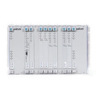
Symmetricom SDU-2000 User Manual (470 pages)
Synchronization Supply Unit and the Synchronization Distribution Unit
Brand:
Symmetricom
| Category:
Power Supply
| Size: 7.45 MB
Table of Contents
Table of Contents
3
How to Use this Guide
19
Purpose of this Guide
20
Who Should Read this Guide
20
Structure of this Guide
21
Conventions Used in this Guide
22
Warnings, Cautions, Recommendations, and Notes
23
Related Documents and Information
24
Where to Find Answers to Product and Document Questions
24
What's New in this Guide
24
Chapter 1 Product Overview
25
Overview
26
SSU-2000 Synchronization Supply Unit
26
Typical System Configurations
27
Timing Signal Generator (TSG) Configuration
27
SSU-2000 Configured as a TSG
27
Primary Reference Source (PRS) Configuration
28
SSU-2000 Configured as a Monitor-Only System
28
SSU-2000 Configured as a Primary Reference Source
28
System Architecture
29
Block Diagram of the SSU-2000
29
Input Section
30
Clock Section
33
Communications Section
33
Output Section
33
Alarms and Events
34
System Components
36
SSU-2000 Main Shelf (Chassis)
36
Components in a Typical SSU-2000 Installation
37
Slot Numbering Assignments
38
Slot Assignments for Specific Modules
38
Rear Panel of the SSU-2000 Main Shelf
39
Location of Power Fuses on the Rear Panel
41
SSU-2000 Family of Modules
42
Clock and Communications Modules
43
Input Modules
44
Output Modules
45
Configuring Redundant Output Modules
46
Input and Output Adapter Panels
47
SSU-2000 Input/Output Connectors
47
I/O Adapter Panels for Input and Output Modules
48
Communications Protocol
49
Software Interface
49
Software Versions
50
Graphical User Interface
50
Versions of Software for the Communications Module
50
Overview of SSU-2000 Operation
51
Synchronization Status Messages (Ssms)
51
ANSI SSM Quality Level Definitions
51
Indicators and Controls
52
SDU-2000 Synchronization Distribution Unit
52
ITU SSM Quality Level Definitions
52
Front View of the SDU-2000 Expansion Shelf
53
Rear View of the SDU-2000 Expansion Shelf
53
Functional Overview
54
SDU-2000 Block Diagram
55
Expansion Shelf Addresses
56
Expansion Shelf Features
56
Setting the Expansion Shelf Address
56
Buffered Clocks
57
SDU Module Features
57
Connector Panel Features
58
Controls and Indicators
58
Chapter 2 Installing the SSU-2000
59
Unpacking and Inspecting the Shelf
60
Preliminary Procedures
60
Installation Tools and Materials
61
Electromagnetic Interference (EMI) Considerations
61
Ventilation Considerations
62
Rack Mounting the SSU-2000
62
SSU-2000 Shelf
62
Shelf and I/O Adapter Rack Mounting
63
I/O Adapter Panels
64
Grounding and Power Input
64
Adapter Cables
64
Frame and Logic Ground Jumpers
65
Making Ground Connections
65
Power Input
66
Making Connections
66
Making I/O Connections
66
Power Terminal Blocks
66
SSU-2000 Rear Panel
67
I/O Module Slot to I/O Connector Relationship
67
Installing Output Summer Adapters
68
Installing the Output Summer Adapter
68
Making Communication Connections
69
Communications Port Assignments
69
Making Ethernet Connections
70
DPDT Slide Switch
70
Local Oscillator Outputs
71
Making Alarm Connections
71
Alarm Terminal Blocks
71
Alarm Relay Connections
72
Connecting Antennas
73
Connecting an SDU-2000 Expansion Shelf
73
SDU Interface (J17 and J15) and Backup Clock (J16) Connectors
74
SDU Interface (J8) and Backup Clock (J9) Connectors
74
Connecting a Single SDU-2000 Expansion Shelf
75
SSU Interface (J8) Expansion Terminator
75
Connecting Additional SDU-2000 Expansion Shelves
76
Wiring Diagram for a Single SDU-2000 Shelf
76
Remote Reset
77
Wiring Diagram for Multiple SDU-2000 Shelves
78
Handling Modules
79
Installing a Module
79
Exchanging a Module
80
Disabling a Module
81
Removing Modules
82
Installation Checklist
83
Powering up the SSU-2000
84
Communications and Buffer Module LED Indications
84
SSU-2000 Power Fuses
84
SDU-2000 Expansion Shelf
85
SSU-2000 Main Shelf
85
Normal System Indications During Turn-Up
85
After Turn up
86
Chapter 3 Provisioning and Operating the SSU-2000
87
Controls and Indicators
88
SSU-2000 Status LED Indicators
88
SSU-2000 Operating Controls
88
Establishing a Connection with the SSU-2000
88
Communicating by Serial Port
88
Direct Connection Using the Serial Port
89
Communicating by Ethernet
90
Adding an Administrator-Level User to the System
91
Adding Users to the System
92
Initial Provisioning
92
Provisioning General Parameters
92
Provisioning GPS Input Modules
94
Provisioning Other Input Modules
94
Provisioning Output Modules
97
Saving the Provisioning Setup
98
Checking Alarm Status
98
Overview of the SSU-2000 Security System
98
Factory Default (Basic) Configuration
99
User Access (Security) Levels
99
Changing Factory Defaults
100
Customizing Other Configuration Options
100
Restoring Factory Defaults
101
Chapter 4 Commissioning
103
Commissioning Test Data Sheet
103
Readiness to Test Checklist
104
SSU-2000 Readiness Checklist
104
SSU-2000 Commands
105
Equipment Requirements
105
Commissioning Tests
106
Testing the Ethernet Communications Interface
106
Testing the EIA-232 Ports
106
Testing the MINOR Alarms
107
Testing the MAJOR Alarms
107
Testing the CRITICAL Alarms
108
Testing the Reference Signals and Selection
108
Testing the Clock Section
109
Testing the Output Section
109
Testing the System Stability and Accuracy (Optional)
110
Commissioning Test Data Sheet
110
Chapter 5 Maintenance and Troubleshooting
111
Responding to SSU-2000 Alarms
112
Preventive Maintenance
112
Corrective Maintenance
113
SSU Corrective Action Table
114
Troubleshooting
115
SDU Corrective Action Table
115
Establishing a Connection
116
Interpreting Status Messages
116
Troubleshooting Guide
116
Alarm and Event Status Breakdown
117
SSU-2000 Troubleshooting Procedures
118
SDU-2000E Troubleshooting Procedures
120
Troubleshooting the SDU-2000
120
Re-Ordering Information
121
Equipment Return Procedure
121
Repacking the Unit
121
Equipment Return Procedure
122
Chapter 6 Clock Module Reference Data
123
Stratum 2E Clock Module
124
Functional Overview
124
Functional Block Diagram
125
Block Diagram of the Stratum 2E Clock Module
125
Status LED Indicators
126
Front Panel of the Stratum 2E Clock Module
126
Stratum 2E Clock Module Status LED Indicators
126
Functional Specifications
127
Stratum 2E Clock Module Specifications
127
Stratum 3E Clock Module
128
Functional Overview
128
Functional Block Diagram
129
Block Diagram of the Stratum 3E Clock Module
129
Status LED Indicators
130
Front Panel of the Stratum 3E Clock Module
130
Stratum 3E Clock Module Status LED Indicators
130
Performance Specifications
131
Stratum 3E Clock Module Performance Specifications
131
Type 1 Clock Module
132
Functional Overview
132
Functional Block Diagram
133
Block Diagram of the Type 1 Clock Module
133
Status LED Indicators
134
Front Panel of the Type 1 Clock Module
134
Type 1 Clock Module Status LED Indicators
134
Functional Specifications
135
Type 1 Clock Module Specifications
135
Communications Module
136
Functional Overview
136
Functional Block Diagram
137
Block Diagram of the Communications Module
137
Status LED Indicators
138
Front Panel of the Communications Module
138
Communications Module Status LED Indicators
138
Communications Module Alarm Logic
139
EIA-232 Ports
140
Communications Module Alarms
140
Ethernet Port
141
Chapter 7 Input Module Reference Data
143
1-Port and 3-Port E1 Input Modules
144
Functional Overview
144
Functional Block Diagram
145
Block Diagram of the 1-Port and 3-Port E1 Input Modules
145
E1 Input Module Alarm Modes
147
Status LED Indicators
150
E1 Input Module Event Reporting
150
Front Panel of the E1 Input Module
151
E1 Input Module Status LED Indicators
151
Software Options
152
E1 Input Module Configuration
152
1-Port and 3-Port DS1 Input Modules
153
Functional Overview
154
Functional Block Diagram
154
Block Diagram of the 1-Port and 3-Port DS1 Input Module
154
SSU-2000 User's Guide 12713020-002-2 Revision D – April
154
DS1 Input Module Alarm Modes
156
Status LED Indicators
159
DS1 Input Module Event Reporting
159
Front Panel of the DS1 Input Module
160
DS1 Input Module Status LED Indicators
160
Configuration Options
161
DS1 Input Module Configuration
161
GPS Input Module
162
Functional Overview
162
Functional Block Diagram
163
Block Diagram of the GPS Input Module
163
Status LED Indicators
164
Front Panel of the GPS Input Module
164
GPS Input Module Status LED Indicators
164
Configuration Data
165
Composite Clock Input Module
165
Functional Overview
165
GPS Input Module Configuration Settings
165
Functional Block Diagram
166
Block Diagram of the Composite Clock Input Module
166
Status LED Indicators
167
Front Panel of the Composite Clock Input Module
167
Composite Clock Input Module Status LED Indicators
167
Factory Default (Basic) Configuration
168
Input Adapter Panels
168
Input Adapter Panel for 1-Port Input Module
168
Composite Clock Input Module Configuration Settings
168
Input Adapter Panel for 3-Port Input Modules
169
Input I/O Adapter for One-Port Input Modules
169
Pinout for the I-Port Input Adapter
169
I/O Adapter for 3-Port Input Modules
170
Pinout for the 3-Port Input Adapter
170
Input Wire-Wrap Adapters
171
Input Wire-Wrap Adapter
171
Chapter 8 Output Module Reference Data
173
E1 Output Module
174
Functional Overview
174
Functional Block Diagram
175
Block Diagram of the E1 Output Module
175
Status LED Indicators
176
Front Panel of the E1 Output Module
176
E1 Output Module Status LED Indicators
176
Performance Specifications
177
E1 Output Module Performance Specifications
177
DS1 Output Module
178
Functional Overview
178
Block Diagram of the DS1 Output Module
178
Status LED Indicators
179
Front Panel of the DS1 Output Module
179
Performance Specifications
180
DS1 Output Module Status LED Indicators
180
DS1 Output Module Performance Specifications
180
Composite Clock Output Module
181
Composite Clock Output Module Overview
181
Functional Block Diagram
182
Block Diagram of the Composite Clock Output Module
182
Status LED Indicators
183
Front Panel of the Composite Clock Output Module
183
Composite Clock Output Module Status LED Indicators
183
Performance Specifications
184
Composite Clock Output Module Performance Specifications
184
E1/2048 Khz Output Module
185
Functional Overview
185
Provisioning the Signal Type
185
Output Squelching
185
Using the Hex Number to Identify Output Ports
186
Identifying Failed Ports from the Hex Digit
187
TL1 Set Commands
187
Bypass Clock (Clock C) Alarms
188
Functional Block Diagram
189
Block Diagram of the E1/2048 Khz Output Module
189
E1/2048 Khz Output Module Status Indicators
190
Front Panel of the E1/2048 Khz Output Module
190
E1/2048 Khz Output Module Status LED Indicators
190
E1/2048 Khz Output Signal Specifications
191
E1/2048 Khz Output Module Specifications
191
2048 Khz Output Module
192
Functional Overview
192
Output Squelching
192
Using the Hex Number to Identify Output Ports
193
Identifying Failed Ports from the Hex Digit
194
Functional Block Diagram
195
Block Diagram of the 2048 Khz Output Module
195
Front Panel of the 2048 Khz Output Module
196
2048 Khz Output Module Status Indicators
197
Performance Specifications
197
Functional Overview
198
Provisioning Output Frequencies
198
Output Module
199
Output Squelching
199
Using the Hex Number to Identify Output Ports
199
Identifying Failed Ports from the Hex Digit
200
Functional Block Diagram
201
Block Diagram of the RS-422 Output Module
201
Status Indicators
202
Front Panel of the RS-422 Output Module
202
Performance Specifications
203
Line Retiming Unit (LRU)
205
Functional Overview
205
Recommended Installation Schematic for the LRU
205
Block Diagram of the DS1 LRU Module
206
Status Indicators
207
Front Panel of the DS1 LRU Four Port Module
207
DS1 LRU Module Status LED Indicators
207
Installing the Line Re-Timing Unit
209
SSU-2000 Recommended Slots for LRM Installation
209
SDU-2000 Recommended Slots for LRM Installation
210
Installing the Cut-Through Assembly in the SSU-2000
212
Installing the Cut-Through Assembly in the SDU-2000
213
SSU-2000 and CTA I/O Pin Description
214
Orientation of T He SSU-2000 I/O and CTA I/O Connector Pins
215
Specifications
216
Wire-Wrap Identification Overlay
216
Line Re-Timing Module Specifications
216
Provisioning the LRM
217
Alarms and Events
217
Buffer Module
218
Status Indicators
218
Front Panel of the Buffer Module
218
Balun Output I/O Adapter Panel for Output Module
219
Buffer Module LED Indicators
219
Output Adapter Panels
220
Balun Output Adapter Panel
220
Output I/O Adapter Panel, DE9 Outputs
220
High-Density Wire-Wrap Output Panel
220
DE9 Output Adapter Panel
221
High-Density Wire-Wrap Output Panels
221
Adapter Accessories
221
Advertisement
Symmetricom SDU-2000 Technical Reference (400 pages)
Synchronization Supply Unit and Synchronization Distribution Unit
Brand:
Symmetricom
| Category:
Portable Generator
| Size: 2.18 MB
Table of Contents
Table of Contents
3
How to Use this Guide
13
Purpose of this Guide
14
Who Should Read this Guide
14
Structure of this Guide
14
Conventions Used in this Guide
15
Warnings, Cautions, Recommendations, and Notes
15
Related Documents and Information
17
Where to Find Answers to Product and Document Questions
17
What's New in this Document
17
Chapter 1 Overview
19
SSU-2000 Control Languages
20
Chapter 2 TL1 Reference
20
Module and Software Revision Levels
21
Communications Module Software Versions
21
TL1 Command Interface
24
TL1 Command and Response Conventions
25
Denied Response Error Codes
30
System Security
32
TL1 Retrieve Commands and Responses
33
User Access Levels
33
Retrieve 2048 Khz Clock Output Parameters
34
Retrieve Alarm Cutoff
36
Retrieve Alarm Elevation Time
37
Retrieve Module Alarms
38
Retrieve Alarm Parameters
40
Retrieve Alarm Status
41
Retrieve All Alarms
42
Retrieve CC Input Parameters
43
Retrieve CC Output Parameters
44
Retrieve Clock Parameters
46
Retrieve Clock Status
47
Retrieve Communication Parameters
48
Retrieve Configuration
49
Retrieve Configuration Date
50
Retrieve DS1/E1 Input Parameters
51
Retrieve DS1/E1 Output Parameters
52
Retrieve DS1 LRM Parameters
54
Retrieve DS1 LRM Status
55
Retrieve DS1 LRM BPV Data
56
Retrieve E1 LRM Parameters
57
Retrieve E1 LRM Status
58
Retrieve E1 LRM BPV Data
59
Retrieve E1/2048 Khz Output Parameters
60
Retrieve Events
62
Retrieve Frequency Data
64
Retrieve Frequency Parameters
65
Retrieve GPS Available Data
66
Retrieve GPS Data
67
Retrieve GPS Input Parameters
69
Retrieve GPS Position
70
Retrieve Header
71
Retrieve Input Data
72
Retrieve Input Reference
73
Retrieve Input Status
74
Retrieve Inventory
75
Retrieve IP Parameters
77
Retrieve Japan Sine Input Parameters
78
Retrieve Japan Sine Output Parameters
79
Retrieve JCC Input Parameters
81
Retrieve JCC Output Parameters
82
Retrieve Keep-Alive Parameters
84
Retrieve LED
85
Retrieve Local Time Offset
86
Retrieve Login Events
87
Retrieve LRM Port Circuit ID
88
Retrieve MTIE Data
89
Retrieve MTIE History
91
Retrieve MTIE Parameters
92
Retrieve Name
93
Retrieve Network Element Type
94
Retrieve NTP Parameters
95
Retrieve NTP Status
96
Retrieve Operating Mode
97
Retrieve Output PQL
98
Retrieve Output Status
99
Retrieve Password Status
101
Retrieve Phase Build-Out Parameters
102
Retrieve Phase Data
103
Retrieve Ping
105
Retrieve Reference Parameters
106
Retrieve Reports
107
Retrieve RS-422 Output Parameters
109
Retrieve Security Log
111
Retrieve Security Parameters
112
Retrieve Setup Parameters
113
Retrieve Signal Fault Alarm Parameters
116
Retrieve SNMP Engine ID Parameter
117
Retrieve SNMP Mode Parameter
118
Retrieve Snmpv2 Manager List
119
Retrieve Snmpv2 User List
120
Retrieve Snmpv3 Manager List
121
Retrieve Snmpv3 Notification Type
122
Retrieve Snmpv3 User List
123
Retrieve TDEV Data
124
Retrieve TDEV History Data
126
Retrieve TL1 Format
127
Retrieve User List
128
TL1 Set Commands
129
Set 2048 Khz Output Parameters
130
Set Active Clock
131
Set Alarm Cutoff
132
Set Alarm Elevation Time Parameters
133
Set Alarm Level Parameters
134
Set CC Input Parameters
135
Set CC Output Parameters
136
Set Clock Parameters
137
Set Clock Autoreturn
138
Set Clock Mode
139
Set Communication Parameters
140
Set Date and Time
141
Set DS1/E1 Input Parameters
142
Set DS1/E1 Output Parameters
143
Set DS1 LRM Parameters
144
Set E1/2048 Khz Output Parameters
145
Set E1/2048 Khz Output Parameters
146
Set E1 LRM Parameters
147
Set Frequency Alarm Threshold Parameters
148
Set GPS Input Parameters
149
Set GPS Position
150
Set Input Reference
151
Set IP Parameters
152
Set Japan Sine Input Parameters
153
Set Japan Sine Output Parameters
154
Set JCC Input Parameters
155
Set JCC Output Parameters
156
Set Keep-Alive Parameter
157
Set Login Events
158
Set LRM Circuit ID
159
Set MTIE Mask
160
Set MTIE Parameters
161
Set Name
162
Set NTP Parameters
163
Set Operating Mode
164
Set Output PQL
165
Set Phase Zero
166
Set RS-422 Output Parameters
167
Set Password Confirm
168
Set Phase Build-Out Parameter
169
Set Security Parameters
170
Set Setup Parameters
171
Set Signal Fault Alarm Parameters
172
Set SNMP Mode Parameter
173
Set Snmpv2 Manager Parameters
174
Set Snmpv2 User Parameter
175
Set Snmpv3 Manager Parameter
176
Set Snmpv3 Notification Parameter
177
Set Snmpv3 User Parameters
178
Set TL1 Format Parameter
179
Set User Parameters
180
Other TL1 Commands
181
Backing up and Restoring the Configuration
182
Chapter 3 ICS Command Reference
185
Overview
186
General Conventions
186
ICS Prompts
187
Line Editing
187
Logon Requirements
187
Command Syntax
188
ICS Commands
190
Alarm
191
Bye
193
Clk
194
Cls
196
Comm
197
Config
199
Shelf Configuration Information
199
Date
202
Doy
203
Elevtime
204
Engine
205
Events
208
Frequency
210
Help
211
Info
213
Input
214
Ioname
218
Keepalive
220
Login
221
Lrm
222
Msg
223
Mtie
224
Name
226
Ntp
227
Opermode
229
Output
230
Pbo
233
Phase
234
Ping
235
Pqltable
236
Ref
238
Reset
240
SSU-2000 Technical Reference 12713020-003-2 Revision F.01 – January
240
Restart
241
Security
242
Setup
243
Snmp
245
Status
248
Systime
249
Tdev
250
Time
252
Tl1Format
253
Users
254
Ver
256
Who
257
Chapter 4 NTP and SNMP
259
NTP Support
260
Server Mode
260
Client Mode
260
Broadcast Mode
261
SNMP Protocol
262
SNMP V2 Details
262
SNMP V3 Details
263
Management Information Base
263
Enabling SNMP
264
Adding a User
264
Adding a Manager IP Address
265
User and Manager Tables
265
Keep-Alive Support
266
Shelf Information
266
Software Information
266
Communications Module Software Version
267
Communications Module Software Versions
267
Chapter 5 Antennas
269
Ordering Information
270
Antenna Kits and Accessories
271
Selecting the Proper Gain Antenna
271
GPS Antennas with Internal LNA
272
Specifications for GPS Antennas with Internal LNA
272
Db L1 GPS Antenna Accessory Kit
273
Transient Eliminators
274
Db and 68 Db L1 GPS Antenna Accessory Kit
274
FCC-250B-90-1.5NFNF Specifications
274
GPS L1 Inline Amplifier
275
GPS L1 Inline Amplifier Specifications
275
GPS L1 Inline Amplifier Assembly
276
Antenna Coaxial Cables
276
Optional Antenna Coaxial Cables
276
Optional Antenna Coaxial Cable Crimper Kits
276
Antenna Cable Specifications
277
Installing Antennas
278
Antenna Connection Overview
278
Planning the Installation
278
Antenna Signal Connections
278
Antenna Installation Tools and Materials
281
Cutting Antenna Cables
282
Installing the Antenna
282
Connecting the Cable to the Antenna
283
Installing the Transient Eliminator
284
Installing the Antenna Cable
285
Connecting the GPS Antenna
285
Antenna Installation Completeness Checklist
285
Optional Accessories
286
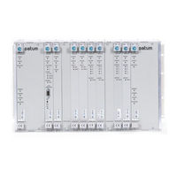
Symmetricom SDU-2000 User Manual (296 pages)
Synchronization Supply Unit and Synchronization Distribution Unit
Brand:
Symmetricom
| Category:
Power Supply
| Size: 4.49 MB
Table of Contents
Table of Contents
3
Table of Contents
15
How to Use this Guide
17
Purpose of this Guide
18
Who Should Read this Guide
18
Conventions Used in this Guide
19
Structure of this Guide
19
Warnings, Cautions, Recommendations, and Notes
20
Related Documents and Information
21
What's New in this Document
22
Where to Find Answers to Product and Document Questions
22
Chapter 1 Product Overview
23
Overview
24
SSU-2000 Synchronization Supply Unit
24
Typical System Configurations
25
Timing Signal Generator (TSG) Configuration
25
SSU-2000 Configured as a TSG
25
Primary Reference Source (PRS) Configuration
26
SSU-2000 Configured as a Monitor-Only System
26
SSU-2000 Configured as a Primary Reference Source
26
System Architecture
27
Block Diagram of the SSU-2000
27
Input Section
28
Clock Section
31
Communications Section
31
Output Section
31
Alarms and Events
32
System Components
34
SSU-2000 Main Shelf (Chassis)
34
Components in a Typical SSU-2000 Installation
35
Slot Numbering Assignments
36
Slot Assignments for Specific Modules
36
Rear Panel of the SSU-2000 Main Shelf
37
Location of Power Fuses on the Rear Panel
39
SSU-2000 Family of Modules
40
Clock and Communications Modules
41
Input Modules
42
Output Modules
44
Configuring Redundant Output Modules
46
SSU-2000 Input/Output Connectors
46
Input and Output Adapter Panels
47
I/O Adapter Panels for Input and Output Modules
48
Communications Protocol
49
Software Interface
49
Basic System Load
50
Software Versions
50
Versions of Software for the Communications Module
50
Graphical User Interface
51
Overview of SSU-2000 Operation
51
Synchronization Status Messages (Ssms)
51
Front View of the SDU-2000 Expansion Shelf
52
Indicators and Controls
52
SDU-2000 Synchronization Distribution Unit
52
Functional Overview
53
Rear View of the SDU-2000 Expansion Shelf
53
Expansion Shelf Features
54
SDU-2000 Block Diagram
55
Buffered Clocks
56
Expansion Shelf Addresses
56
SDU Module Features
56
Setting the Expansion Shelf Address
56
Connector Panel Features
57
Controls and Indicators
57
Chapter 2 Installing the SSU-2000
59
Unpacking and Inspecting the Shelf
60
Preliminary Procedures
60
Electromagnetic Interference (EMI) Considerations
61
Installation Tools and Materials
61
Ventilation Considerations
62
Rack Mounting the SSU-2000
62
SSU-2000 Shelf
62
Shelf and I/O Adapter Rack Mounting
63
I/O Adapter Panels
64
Making Ground and Power Connections
64
Making Ground Connections
65
Frame and Logic Ground Jumpers
65
Connecting Power
66
Making Signal Connections
66
Making I/O Connections
66
Power Terminal Blocks
66
SSU-2000 Rear Panel
67
I/O Module Slot to I/O Connector Relationship
67
Installing Output Summer Adapters
68
Installing the Output Summer Adapter
68
Communications Port Assignments
70
Making Communication Connections
70
DTE/DCE Slide Switch
71
Communications Port Assignments
71
Local Oscillator Outputs
72
Making Ethernet Connections
72
Remote Reset
72
Alarm Terminal Blocks
73
Making Alarm Connections
73
Alarm Relay Connections
74
Connecting an SDU-2000 Expansion Shelf
75
Connecting Antennas
75
SDU Interface (J17 and J15) and Backup Clock (J16) Connectors
76
SDU Interface (J8) and Backup Clock (J9) Connectors
76
SSU Interface (J8) Expansion Terminator
76
Connecting a Single SDU-2000 Expansion Shelf
77
Connecting Additional SDU-2000 Expansion Shelves
78
Wiring Diagram for a Single SDU-2000 Shelf
78
Wiring Diagram for Multiple SDU-2000 Shelves
80
Handling Modules
81
Installing a Module
81
Exchanging a Module
82
Disabling a Module
83
Removing Modules
84
Installation Checklist
85
Communications and Buffer Module LED Indications
86
Powering up the SSU-2000
86
SSU-2000 Power Fuses
86
Normal System Indications During Turn-Up
87
SDU-2000 Expansion Shelf
87
SSU-2000 Main Shelf
87
After Turn up
88
Chapter 3 Provisioning and Operating the SSU-2000
89
Controls and Indicators
90
SSU-2000 Operating Controls
90
SSU-2000 Status LED Indicators
90
Establishing a Connection with the SSU-2000
90
Communicating by Serial Port
91
Direct Connection Using the Serial Port
91
Communicating by Ethernet
92
Overview of the SSU-2000 Security System
93
Firmware Requirements for Security Features
94
Adding an Administrator-Level User to the System
95
User Access Levels
95
Adding Users to the System
96
Setting Security Parameters
98
Logging in to the SSU-2000
102
Logging in with an Expired Password
103
Initial Provisioning
105
Logging off of the SSU-2000
105
Provisioning General Parameters
105
Adding or Enabling a Module
106
Disabling a Module
107
Removing a Module
107
Provisioning GPS Input Modules
108
Provisioning Other Input Modules
109
Provisioning Output Modules
111
Saving the Provisioning Setup
112
Checking Alarm Status
113
Factory Default (Basic) Configuration
113
Retrieving Factory Defaults
113
Changing Factory Defaults
114
Restoring Factory Defaults
114
Customizing Other Configuration Options
115
Retrieving the User Configuration
115
Backing up and Restoring Configurations
116
Backing up the Configuration
116
Using ICS Commands
116
Using TL1 Commands
116
Restoring the Configuration
117
Using ICS Commands
117
Using TL1 Commands
117
Chapter 4 Commissioning
119
Readiness to Test Checklist
120
SSU-2000 Readiness Checklist
120
SSU-2000 Commands
121
Equipment Requirements
121
Commissioning Tests
122
Testing the EIA-232 Ports
122
Testing the Ethernet Communications Interface
122
Testing the MAJOR Alarms
123
Testing the MINOR Alarms
123
Testing the CRITICAL Alarms
124
Testing the Reference Signals and Selection
124
Testing the Clock Section
125
Testing the Output Section
125
Testing the System Stability and Accuracy (Optional)
126
Commissioning Test Data Sheet
126
Chapter 5 Maintenance and Troubleshooting
127
Responding to SSU-2000 Alarms
128
Preventive Maintenance
128
Corrective Maintenance
129
SSU Corrective Action Table
130
SDU Corrective Action Table
131
Troubleshooting
131
Establishing a Connection
132
Troubleshooting Guide
132
Alarm and Event Status Breakdown
133
Interpreting Status Messages
133
SSU-2000 Troubleshooting Procedures
134
SDU-2000E Troubleshooting Procedures
136
Troubleshooting the SDU-2000
136
Equipment Return Procedure
137
Re-Ordering Information
137
Repacking the Unit
137
Contacting Technical Support
138
Equipment Return Procedure
138
Chapter 6 Clock and Communications Module Reference Data
139
Stratum 2E Clock Module
140
Functional Overview
140
Functional Block Diagram
141
Block Diagram of the Stratum 2E Clock Module
141
Status LED Indicators
142
Front Panel of the Stratum 2E Clock Module
142
Stratum 2E Clock Module Status LED Indicators
142
Functional Specifications
143
Stratum 2E Clock Module Specifications
143
Stratum 3E Clock Module
144
Functional Overview
144
Functional Block Diagram
145
Block Diagram of the Stratum 3E Clock Module
145
Status LED Indicators
146
Front Panel of the Stratum 3E Clock Module
146
Stratum 3E Clock Module Status LED Indicators
146
Performance Specifications
147
Stratum 3E Clock Module Performance Specifications
147
Type 1 Clock Module
148
Functional Overview
148
Functional Block Diagram
149
Block Diagram of the Type 1 Clock Module
149
Status LED Indicators
150
Front Panel of the Type 1 Clock Module
150
Type 1 Clock Module Status LED Indicators
150
Functional Specifications
151
Type 1 Clock Module Specifications
151
Communications Module
152
Functional Overview
152
Functional Block Diagram
153
Block Diagram of the Communications Module
153
Status LED Indicators
154
Front Panel of the Communications Module
154
Communications Module Status LED Indicators
154
Communications Module Alarm Logic
155
EIA-232 Ports
156
Communications Module Alarms
156
Ethernet Port
157
Resetting the Module
157
Chapter 7 Input Module Reference Data
159
1-Port and 3-Port E1 Input Modules
160
Functional Overview
160
Functional Block Diagram
161
Block Diagram of the 1-Port and 3-Port E1 Input Modules
161
E1 Input Module Alarm Modes
163
E1 Input Module Event Reporting
166
E1 Input Module Status LED Indicators
167
Front Panel of the E1 Input Module
167
Status LED Indicators
167
Configuration Options
168
E1 Input Module Configuration Settings
168
1-Port and 3-Port DS1 Input Modules
170
Functional Overview
170
Block Diagram of the 1-Port and 3-Port DS1 Input Module
171
Functional Block Diagram
171
DS1 Input Module Alarm Modes
173
DS1 Input Module Event Reporting
176
DS1 Input Module Status LED Indicators
177
Front Panel of the DS1 Input Module
177
Status LED Indicators
177
Configuration Options
178
DS1 Input Module Configuration Settings
178
Functional Overview
180
GPS Input Module
180
Block Diagram of the GPS Input Module
181
Functional Block Diagram
181
Front Panel of the GPS Input Module
182
GPS Input Module Status LED Indicators
182
Status LED Indicators
182
Configuration Options
183
GPS Input Module Configuration Settings
183
Composite Clock Input Module
184
Functional Overview
184
Block Diagram of the Composite Clock Input Module
185
Functional Block Diagram
185
Composite Clock Input Module Status LED Indicators
186
Front Panel of the Composite Clock Input Module
186
Status LED Indicators
186
Composite Clock Input Module Configuration Settings
187
Configuration Options
187
Functional Overview
187
Japanese Sine Wave Input Module
187
Block Diagram of the Japanese Sine Wave Input Module
188
Functional Block Diagram
188
Front Panel of the Japanese Sine Wave Input Module
191
Status LED Indicators
191
Configuration Options
192
Japanese Sine Wave Input Module Configuration Settings
192
Japanese Sine Wave Input Module Status LED Indicators
192
Functional Overview
194
Japanese Composite Clock Input Module
194
Block Diagram of the Japanese Composite Clock Input Module
195
Functional Block Diagram
195
Front Panel of the Japanese Composite Clock Input Module
196
Japanese Composite Clock Input Module Status LED Indicators
196
Status LED Indicators
196
Configuration Options
197
Input Adapter Panel for 1-Port Input Module
197
Input Adapter Panels
197
Japanese Composite Clock Input Module Configuration Settings
197
Input I/O Adapter for One-Port Input Modules
198
I/O Adapter for 3-Port Input Modules
199
Input Adapter Panel for 3-Port Input Modules
199
Input Wire-Wrap Adapters
200
Input Wire-Wrap Adapter
201
Chapter 8 Output Module Reference Data
203
E1 Output Module
204
Functional Overview
204
Functional Block Diagram
205
Block Diagram of the E1 Output Module
205
Status LED Indicators
206
Front Panel of the E1 Output Module
206
Performance Specifications
207
DS1 Output Module
208
Functional Overview
208
Block Diagram of the DS1 Output Module
208
Status LED Indicators
209
Front Panel of the DS1 Output Module
209
Performance Specifications
210
Composite Clock Output Module
211
Functional Overview
211
Functional Block Diagram
212
Block Diagram of the Composite Clock Output Module
212
Status LED Indicators
213
Front Panel of the Composite Clock Output Module
213
Performance Specifications
214
Japanese Composite Clock Output Module
215
Functional Overview
215
Functional Block Diagram
216
Block Diagram of the Japanese Composite Clock Output Module
216
Status LED Indicators
217
Front Panel of the Japanese Composite Clock Output Module
217
Configuration Options
218
Japanese Sine Wave Output Module
219
Functional Block Diagram
219
Functional Overview
219
Block Diagram of the Japanese Sine Wave Output Module
219
Using the Hex Number to Identify Output Ports
221
Status LED Indicators
224
Front Panel of the Japanese Sine Wave Output Module
224
Configuration Options
225
E1/2048 Khz Output Module
225
Functional Overview
226
Using the Hex Number to Identify Output Ports
227
Functional Block Diagram
230
Block Diagram of the E1/2048 Khz Output Module
230
Status LED Indicators
231
Front Panel of the E1/2048 Khz Output Module
231
Performance Specifications
232
2048 Khz Output Module
233
Functional Block Diagram
233
Functional Overview
233
Block Diagram of the 2048 Khz Output Module
234
Using the Hex Number to Identify Output Ports
235
Status LED Indicators
237
Front Panel of the 2048 Khz Output Module
237
Performance Specifications
238
RS-422 Output Module
239
Functional Block Diagram
239
Functional Overview
239
Block Diagram of the RS-422 Output Module
240
Using the Hex Number to Identify Output Ports
241
Status LED Indicators
243
Front Panel of the RS-422 Output Module
243
Performance Specifications
244
DS1 Line Retiming Unit (LRU)
245
Functional Overview
247
Recommended Installation Schematic for the DS1 LRU
247
Block Diagram of the DS1 LRU Module
248
Status LED Indicators
249
Front Panel of the DS1 LRU Four-Port Module
249
Installing the Line Re-Timing Unit
250
Recommended SSU-2000 Slots for Installing the DS1 LRM
251
SDU-2000 Recommended Slots for DS1 LRM Installation
252
Installing the Cut-Through Assembly in the SSU-2000
252
Installing the Cut-Through Assembly in the SDU-2000
254
Orientation of the SSU-2000 I/O and CTA I/O Connector Pins
256
Provisioning the DS1 Line Re-Timing Module
257
Specifications
257
Wire-Wrap Identification Overlay
257
Alarms and Events
258
E1 Line Re-Timing Unit
258
Functional Overview
258
E1 LRM Block Diagram
259
Status LED Indicators
260
Front Panel of the E1 LRM
260
Installing the E1 Line Re-Timing Module
261
Installing the Output Panels
262
Sample Rack Mounting with Input Module, SSU-2000, and Output Panel
262
Provisioning the E1 Line Re-Timing Module
263
Specifications
263
DE9 Output Panel for the E1 LRU
263
BNC Output Panel for the E1 LRU
263
Alarms and Events
264
Buffer Module
264
Status Indicators
264
Front Panel of the Buffer Module
265
Output Adapter Panels
266
Balun Output Adapter Panel
266
DE9 Output Adapter Panel
266
Adapter Accessories
267
High-Density Wire-Wrap Output Panels
267
Chapter 9 Hardware Configuration Guide
269
Configuring a Conventional SSU/TSG System
270
Configuring a Primary Reference Source (PRS) System
270
Configuring a Monitor-Only System
271
Configuring a Subtending SSU
272
Functional Description
273
Input Section
273
Output Section
275
Setting Subtending Parameters
275
Changing to Subtending SSU Mode
276
Changing from Subtending SSU Mode
277
Installing Software
277
Required Hardware
277
SSU-2000 Configuration Chart
278
SSU-2000 User's Guide
279
Index
289
Advertisement
Advertisement
Related Products
Symmetricom SSU-2000
Symmetricom SDU-2000e
Symmetricom SyncServer S100
Symmetricom SSU-2000e
Symmetricom Categories
Test Equipment
Clock
Server
GPS
Amplifier
More Symmetricom Manuals
Login
Sign In
OR
Sign in with Facebook
Sign in with Google
Upload manual
Upload from disk
Upload from URL