
Related Manuals for Symmetricom SSU-2000


Summary of Contents for Symmetricom SSU-2000
- Page 1 SSU-2000 Synchronization Supply Unit and the SDU-2000 Synchronization Distribution Unit User Guide Revision D – April 2004 Part Number 12713020-002-2...
- Page 2 2300 Orchard Parkway San Jose, CA 95131-1017 U.S.A. http://www.symmetricom.com Copyright © 1999–2004 Symmetricom, Inc. All rights reserved. Printed in U.S.A. All product names, service marks, trademarks, and registered trademarks used in this document are the property of their respective owners.
-
Page 3: Table Of Contents
SSU-2000 Main Shelf (Chassis) ........ - Page 4 Rack Mounting the SSU-2000 ........
- Page 5 SSU-2000 Status LED Indicators ........88...
- Page 6 Responding to SSU-2000 Alarms ........
- Page 7 Output Squelching..........192 12713020-002-2 Revision D – April 2004 SSU-2000 User’s Guide...
- Page 8 SSU-2000 Configuration Chart ........
- Page 9 SSU-2000 Control Languages ........
- Page 10 SSU-2000 Shelf Specifications ........
- Page 11 Other Reference Documents ......... . 453 12713020-002-2 Revision D – April 2004 SSU-2000 User’s Guide 11...
- Page 12 SSU-2000 User’s Guide 12713020-002-2 Revision D – April 2004...
- Page 13 SSU-2000 Power Fuses ........
- Page 14 SSU-2000 Rear Panel ........
- Page 15 User Access (Security) Levels....... . . 99 SSU-2000 Readiness Checklist ......104 Commissioning Test Data Sheet .
- Page 16 Files Required for Upgrading the Firmware..... . 231 SSU-2000 System Components ......233 Clock Module Alarm Messages .
- Page 17 SDU-2000 System Specifications ......445 12713020-002-2 Revision D – April 2004 SSU-2000 User’s Guide 17...
- Page 18 SSU-2000 User’s Guide 12713020-002-2 Revision D – April 2004...
-
Page 19: How To Use This Guide
Structure of This Guide Conventions Used in This Guide Warnings, Cautions, Recommendations, and Notes Related Documents and Information Where to Find Answers to Product and Document Questions What’s New In This Guide 12713020-002-2 Revision D – April 2004 SSU-2000 User’s Guide... -
Page 20: Purpose Of This Guide
Symmetricom SSU-2000 Synchronization Supply Unit (SSU-2000). It also includes appendixes that describe alarms and events, the languages that you use to communicate with the SSU-2000, default values, and other information. Who Should Read This Guide... -
Page 21: Structure Of This Guide
Contains detailed information on the Input modules available for Reference Data use in the SSU-2000. Chapter 8, Output Module Describes the Output modules available for use in the SSU-2000 Reference Data and in the SDU-2000. Chapter 9, Hardware Describes how to configure the SSU-2000 in several modes, and Configuration Guide lists part number for shelves, modules, and accessories. -
Page 22: Conventions Used In This Guide
Typographical Conventions – This guide uses the typographical conventions described in the table below. When text appears ... it means: this way... SSU-2000 User’s Guide The title of a document. An operating mode, alarm state, status, or chassis label. CRITICAL IOC1 Select File, Open... -
Page 23: Warnings, Cautions, Recommendations, And Notes
Note: All notes use this symbol. Notes contain installation, operation, or maintenance procedures, practices, conditions, or statements, that alert you to important information, which may make your task easier or increase your understanding. 12713020-002-2 Revision D – April 2004 SSU-2000 User’s Guide... -
Page 24: Related Documents And Information
Where to Find Answers to Product and Document Questions For additional information about the products described in this guide, please contact your Symmetricom representative or your local sales office. You can also contact us on the web at www.symmetricom.com. What’s New In This Guide... -
Page 25: Chapter 1 Product Overview
Chapter 1 Product Overview This chapter describes the SSU-2000, and provides a theory of operation for the unit. The SDU-2000 expansion shelf is introduced and described. In This Chapter Overview Typical System Configurations System Architecture System Components Communications Protocol Overview of SSU-2000 Operation... -
Page 26: Overview
The SSU-2000 conforms to specifications for International, European and North American applications as a Primary Reference Source (PRS), and Synchronization Supply Unit (SSU), and Timing Signal Generator (TSG). The SSU-2000 allows for the integration of a variety of synchronization reference schemes including GPS and land line DS1/E1. -
Page 27: Typical System Configurations
IGNORE, REPORT, ALARM, or FAIL. Typical System Configurations The modular design of the SSU-2000 permits a great deal of flexibility in configuring the system components for a variety of applications. Three of the more common configurations include:... -
Page 28: Primary Reference Source (Prs) Configuration
The remaining input signals are then compared to the phase-locked oscillators (and indirectly to the designated input reference). The SSU-2000 continuously monitors the integrity of the incoming timing signal. The operator defines input acceptance criteria and sets parameters for alarming. -
Page 29: System Architecture
SSU-2000 shelf to meet a variety of telecommunications synchronization application requirements. Modules can be inserted or removed from the SSU-2000 while the shelf is operational without any degradation of output signals. Each module supports the management of critical, major, and minor alarms. -
Page 30: Input Section
Wander is reported in terms of Maximum Time Interval Error (MTIE) and Time Deviation (TDEV). The data is then stored for use in the SSU-2000 and reported through the Communications module. You can install one or two GPS Input modules that use the satellite-based Global Positioning System signals as a synchronization reference.The Input signal types... - Page 31 You can set the input selection to either Priority or PQL. The reference switching mode is either Autoreturn, Autoswitch, or No switching. 12713020-002-2 Revision D – April 2004 SSU-2000 User’s Guide...
- Page 32 Priority setting; if all inputs have the same Priority level, then the input with the highest PQL (quality level, SSM) is used. If you select PQL mode, the SSU-2000 selects the input reference with the highest assigned PQL level or associated SSM; if all inputs have the same PQL/SSM value, then the input with the highest Priority levels is used.
-
Page 33: Output Section
(one that is free from input faults while meeting acceptable frequency and MTIE specifications). The SSU-2000 controls clock frequency by adjusting the control value of the Direct Digital Synthesis (DDS) function in each Clock module. The adjustments are processor-controlled and based on measurements performed and computed in the Input module(s). -
Page 34: Alarms And Events
The Communications module provides an interface between the user and the SSU-2000 system. This interface allows the user to display and control much of the activity in the SSU-2000 system and within the optional SDU-2000 expansion system. - Page 35 The REPORT mode option is used to report alarm indications only. An ALARM command is available in the SSU-2000 that allows a user to view the current status of alarm indications on the unit and set alarm delay intervals and activation levels.
-
Page 36: System Components
LEDs on the front panel of modules. Fail Mode In the FAIL mode, the SSU-2000 removes the failed module from service or usability to prevent interruption of the system. For example, a FAIL event detected in Clock A causes a switchover from Clock A to Clock B, effectively removing Clock A from the system. -
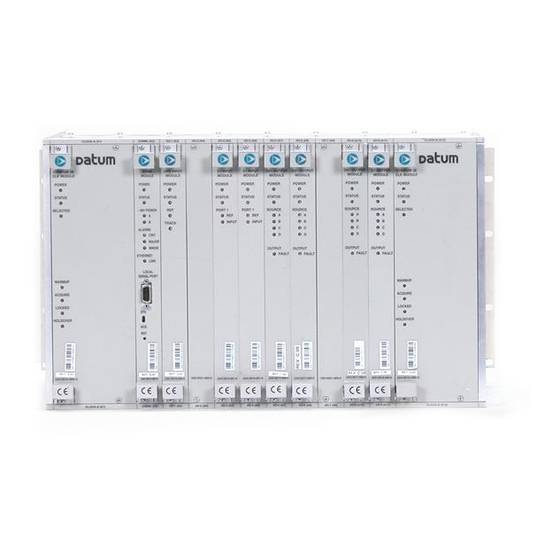
Page 37: Components In A Typical Ssu-2000 Installation
Components in a Typical SSU-2000 Installation Module Assignments All SSU-2000 modules are equipped with card ejectors and plug in from the front of the shelf. Each module is secured in the shelf with captive fasteners.The module assignments for the SSU-2000 main shelf are listed in... -
Page 38: Slot Numbering Assignments
As indicated in Figure 1-7, the SSU-2000 modules are installed in slots A1 through A12, numbered left to right as viewed from the front of the shelf. The first or left-most slot, A1, is assigned to the primary clock module (Clock A). Slot A2 is assigned to the Communications module and slots A3 through A11 are assigned to various combinations of input modules and output modules. -
Page 39: Rear Panel Of The Ssu-2000 Main Shelf
System Components Main Shelf Connections The rear panel of the main shelf contains the connection terminal strips, BNC connectors, and SCSI-II connectors that are used to connect the SSU-2000 to other system components. These connection features are described in Figure 1-8. - Page 40 The main shelf accepts redundant –48 vDC power inputs from external supplies and makes these inputs available to the modules via the motherboard connectors anytime the 5-Amp fuses are installed on the rear of the SSU-2000 main shelf. An On/Off switch is not provided, preventing anyone from accidently shutting down the system.
-
Page 41: Location Of Power Fuses On The Rear Panel
Location of Power Fuses on the Rear Panel Antenna Connectors The SSU-2000 contains two TNC connectors to allow for connection of a radio antenna. Connector J6 is wired into I/O slot A3 and connector J7 is wired into I/0 slot A5 (the only slots that can be used for installing a Radio input module). A variety... -
Page 42: Ssu-2000 Family Of Modules
Main Shelf Power Connections The SSU-2000 main shelf contains provisions for connecting redundant –48 vDC external power inputs (designated A and B input power). The power supplies, located on the internal modules, can accept input power in the range of –37 to –72 vDC. -
Page 43: Clock And Communications Modules
All SSU-2000 modules have an integrated CPU with firmware and are software configurable. Each module slot also has three pins connected together on its assigned Hybrid DIN connector which permits the system to detect when a particular module is removed. -
Page 44: Input Modules
The DS1 and E1 Input modules are available with both 1-Port and 3-Port configurations. These modules receive signals and perform phase measurement comparisons with the Clock modules that are installed in the SSU-2000. The Clock modules use this information to phase and frequency lock to the incoming signal. -
Page 45: Output Modules
SSU-2000 Family of Modules GPS Input Module The GPS Input module is a one-port card that can only be installed in the SSU-2000 main shelf. The module is used to correct the frequency of the oscillator on the Clock module. It monitors and reports the status and performance of the module and radio signals that it receives. -
Page 46: Configuring Redundant Output Modules
SSU-2000 Family of Modules E1/2048 kHz Output Module The E1/2048 kHz Output module can be installed in the SSU-2000 to generate and monitor 20 independent E1/2048kHz output signals. If the module is inserted into an SDU-2000 expansion shelf, a fourth 4 kHz clock (D clock) is available. If the input signal PQL drops below a user-specified level, then the outputs can be squelched. -
Page 47: Input And Output Adapter Panels
All SSU-2000 connections are made on the rear of the Adapter panels; the connections to the telecommunications system are on the front of the Adapter panels. -
Page 48: I/O Adapter Panels For Input And Output Modules
Product Overview Input and Output Adapter Panels There are four adapter panels available for use with the SSU-2000 Input and Output modules including: Input I/O adapter for 3-port Input modules (DS1 or E1) – one adapter panel is required for each 3-port Input module used in the system. -
Page 49: Communications Protocol
GPS receiver or local timing source. The SSU-2000 implements the NTP v.3 (RFC 1305) version. It can run as a server application and a client application. In addition, a broadcast mode may be implemented as either a server or client. -
Page 50: Software Versions
Software Versions There are six different versions of software available for the SSU-2000, as indicated Table 1-2. The functionality and commands that are available vary from one version of software version to the next, depending on the specific features of the... -
Page 51: Overview Of Ssu-2000 Operation
After initial installation and configuration is completed, the SSU-2000 is capable of unattended operation. After power-up, where the external power supplies are turned on so that they supply power to the main shelf, the SSU-2000 performs a self-diagnostic test routine and properly initializes the hardware. Any active Alarms are time tagged and reported as Events. -
Page 52: Indicators And Controls
The SSU-2000 handles SSMs in accordance with T1X1.3 TR33, T1.101-1999, GR-253, and 379-CORE. Indicators and Controls All modules installed in the SSU-2000 main shelf and the SDU-2000 expansion shelf contain status indicator lamps for displaying status. The LED indicators for each module are described in... -
Page 53: Front View Of The Sdu-2000 Expansion Shelf
–48/60 vDC powered telecommunication transmission equipment installed in telecommunication centers with inside telecom signal connections. The farthest Expansion shelf may be located up to 200 feet (61 meters) from the SSU-2000 main shelf. Figure 1-13. Rear VIew of the SDU-2000 Expansion Shelf 12713020-002-2 Revision D –... -
Page 54: Functional Overview
1.544 Mbps (DS1) or 2048 kbit/s (E1) using one of three 4 KHz clocks supplied by the clock oscillators in the SSU-2000 main shelf. The phase locked clock signal is buffered and summed with a companion Output module in redundant pairs to generate a set of 20 independent output clock signals for distribution to large networks. -
Page 55: Sdu-2000 Block Diagram
Product Overview SDU-2000 Synchronization Distribution Unit Figure 1-14. SDU-2000 Block Diagram 12713020-002-2 Revision D – April 2004 SSU-2000 User’s Guide... -
Page 56: Expansion Shelf Features
Clock Source The clock inputs for the first SDU-2000 expansion shelf in an SSU-2000 system are supplied by the A and B Clock modules in the main shelf. A multi-pin connector on the rear panel of the SSU-2000 (labeled J8 SDU Interface) provides the reference signals from the main shelf Clock modules for use by the SDU-2000 expansion shelves. -
Page 57: Buffered Clocks
All modules are individually fused to protect the system in case of a short circuit on any one module The SSU-2000 and the SDU-2000 share common Output modules All modules have front panel LED status indicators All modules are equipped with ejector tabs for ease of installation and removal... -
Page 58: Connector Panel Features
All modules installed in the SDU-2000 expansion shelf contain LED status indicators for displaying status. Any faults from the installed modules are sent to the SSU-2000 Communications module through the buffer modules; the appropriate alarm relays are set and communication status is sent to alert users of any events that exceed specified alarm thresholds. -
Page 59: Chapter 2 Installing The Ssu-2000
Chapter 2 Installing the SSU-2000 This chapter provides guidelines and procedures for installing and powering up the SSU-2000 Synchronization Supply Unit. In This Chapter Unpacking and Inspecting the Shelf Preliminary Procedures Rack Mounting the SSU-2000 Grounding and Power Input Making Connections... -
Page 60: Unpacking And Inspecting The Shelf
Installing the SSU-2000 Unpacking and Inspecting the Shelf Unpacking and Inspecting the Shelf The SSU-2000 is packaged to protect it from normal shock, vibration and handling damage. Care should be taken during unpacking and installation to avoid damaging the unprotected unit. -
Page 61: Installation Tools And Materials
ProComm Plus Electromagnetic Interference (EMI) Considerations Electromagnetic interference (EMI) from one instrument can adversely affect the operation of nearby equipment. To prevent the SSU-2000 from interfering with other equipment, it must be installed and operated as described in the following paragraphs. -
Page 62: Ventilation Considerations
12 in (30.5 cm), and a width of 19 in (48.3 cm). When installing more than one SSU-2000, each unit must have at least one inch (2.5 cm) of clearance above and below to ensure proper cooling. There should be at least three inches (7.6 cm) of free space below the bottom shelf. -
Page 63: Shelf And I/O Adapter Rack Mounting
Installing the SSU-2000 Rack Mounting the SSU-2000 Figure 2-1. Shelf and I/O Adapter Rack Mounting 3. If not using expansion shelves, verify that the Bus Termination Assembly is inserted into J9 on the rear panel of the main shelf. Recommendation: When possible, install the shelf at eye level to aid in viewing and connecting cables. -
Page 64: I/O Adapter Panels
Output I/O adapter panels below the shelf. Grounding and Power Input The SSU-2000 shelf has redundant -48VDC power input connections labeled A-BUS and B-BUS. The A-BUS connection is a 2-position #6 terminal block in the upper left corner of the rear panel, and the B-BUS connection is a 2-position #6 terminal block in the upper right corner of the rear panel. -
Page 65: Making Ground Connections
Installing the SSU-2000 Grounding and Power Input Making Ground Connections After the SSU-2000 is installed in a suitable rack, connect the shelf to a proper earth ground. 1. Run a cable from the frame ground (FG) lug to earth ground. -
Page 66: Power Input
Figure 2-3. Power Terminal Blocks Making Connections Making I/O Connections The SSU-2000 shelf has I/O interface connections for connecting the SSU-2000 to the corresponding I/O adapter panels. Refer to Chapter 7, Input Module Reference Data, and Chapter 8, Output Module Reference Data,... -
Page 67: Ssu-2000 Rear Panel
Installing the SSU-2000 Making Connections All I/O connections are made through the nine 50-Pin Micro-D female connectors, J10 through J18. Each connector is associated with a specific chassis slot. Table lists the relationship between the I/O slot and the rear panel connector. -
Page 68: Installing Output Summer Adapters
Caution: To avoid possible electrostatic discharge problems after removing an Output Summer adapter, you must replace the screws securing the I/O connectors on the rear panel of the SSU-2000. 2. Install Output Summer adapters on all I/O connector pairs that require... -
Page 69: Making Communication Connections
Installing the SSU-2000 Making Connections Making Communication Connections The rear panel of the SSU-2000 shelf has connections for three communications interfaces, two EIA-232 Serial Port connections, and one Ethernet connection. These ports allow communication between the SSU-2000 and a terminal or PC. -
Page 70: Making Ethernet Connections
The default EIA-232 settings for both serial ports are 9600 baud, no parity, 8 data bits, 1 stop bit, echo on, ASCII mode, and handshaking disabled. To change these settings, connect the SSU-2000 to a terminal device or PC using a serial communications program protocol. See... -
Page 71: Local Oscillator Outputs
BNC connector J2 labeled LOCAL OSC-B. The bodies of these BNCs are connected to frame ground. Making Alarm Connections The SSU-2000 has two alarm terminal blocks located on the rear panel for attaching external circuits to the SSU-2000, and are shown in Figure 2-7. -
Page 72: Alarm Relay Connections
Energized: alarm COM – NO Perform the following steps to ensure proper alarm connections to the SSU-2000. 1. Remove both fuses from the rear panel. 2. Locate the ALARM terminal blocks connectors labeled MAJOR ALARMS (TB1) and MINOR ALARMS (TB2) on the rear panel. -
Page 73: Connecting Antennas
J8, a DB25S female connector with locking post, labeled SDU INTERFACE, and connector J9, a BNO connector labeled SDU BACKUP CLK. These connectors are on the rear panel of the SSU-2000, and are shown in Figure 2-8. The corresponding connectors on the rear panel of the SDU-2000 are shown in Figure 2-9. -
Page 74: Sdu Interface (J8) And Backup Clock (J9) Connectors
Expansion Terminator. Install the SDU-2000 Expansion shelf using the procedure described in Rack Mounting the SSU-2000, on page 62. Then install power and ground connections using the procedure described in Grounding and Power Input, on page 64. SSU-2000 User’s Guide... -
Page 75: Connecting A Single Sdu-2000 Expansion Shelf
SDU-2000 installation. 1. Remove the Expansion Terminator (part number 12013040-000-0, if installed) from J8 on the rear panel of the SSU-2000. Set the terminator aside for use in step 3, below. 2. Attach one end of the Expansion Cable (part number 12013050-xxx-0; the xxx indicates the length of the cable) to J8 on the rear panel of the SSU-2000. -
Page 76: Connecting Additional Sdu-2000 Expansion Shelves
Installing the SSU-2000 Connecting an SDU-2000 Expansion Shelf Figure 2-11. Wiring Diagram for a Single SDU-2000 Shelf Connecting Additional SDU-2000 Expansion Shelves To connect additional SDU shelves to an SDU, use the following procedure. Figure 2-12 illustrates the wiring for a system with three SDU-2000 shelves. -
Page 77: Remote Reset
Remote Reset The SSU-2000 shelf has a remote reset input which can be used to remotely initiate system firmware reset if the need should arise. The remote reset connections are made via connector J19, which is a BNO connector labeled REMOTE RESET. A contact closure across the two pins resets the firmware. -
Page 78: Wiring Diagram For Multiple Sdu-2000 Shelves
Installing the SSU-2000 Remote Reset Figure 2-12. Wiring Diagram for Multiple SDU-2000 Shelves SSU-2000 User’s Guide 12713020-002-2 Revision D – April 2004... -
Page 79: Handling Modules
Handling Modules Handling Modules The SSU-2000 shelf has twelve plug-in module slots, numbered A1 through A12, from left to right looking at the front of the shelf. Each module slot has a specific address and has two hybrid DIN connectors associated with it on the backplane. -
Page 80: Exchanging A Module
Use this procedure to exchange one type of module with the same type or a different type of module in the same slot. The example commands are for slot 3 in the main shelf. 1. Connect to the SSU-2000 using one of the methods described in Establishing a Connection With the SSU-2000, on page 88. -
Page 81: Disabling A Module
Use this command to temporarily disable a module without removing it from the SSU-2000 registry. All outputs from the disabled module will turn off, unless a summer adapter is installed on the I/O connector on the rear panel of the shelf. The example commands are for slot 3 in the main shelf. -
Page 82: Removing Modules
This procedure describes how to permanently remove a module from the shelf. Note: Modules can be removed and inserted while system power is supplied without damaging modules or affecting system operation. 1. Connect to the SSU-2000 using one of the methods described in Establishing a Connection With the SSU-2000, on page 88. -
Page 83: Installation Checklist
2. Remove the A-BUS and B-BUS fuses from the rear of the unit. 3. Ensure shelf and I/O adapters are securely attached to the mounting rack. 4. Ground the SSU-2000 using the Frame Ground lug. 5. Measure between ground and chassis and verify no voltage exists between them. -
Page 84: Powering Up The Ssu-2000
–48V Power polarity is reversed Powering Up the SSU-2000 The SSU-2000 is not equipped with a Power switch. Power to the SSU-2000 is controlled by two 5-amp fuses located on the rear of the SSU-2000 main chassis as shown in Figure 2-13. -
Page 85: Ssu-2000 Main Shelf
Installing the SSU-2000 Normal System Indications During Turn-Up SSU-2000 Main Shelf To power up the SSU-2000 main shelf, insert the two fuses into the fuse slots on the rear panel of the SSU-2000 main chassis (see Figure 2-13). SDU-2000 Expansion Shelf The SDU-2000 expansion shelf is not equipped with a Power switch. -
Page 86: After Turn Up
Installing the SSU-2000 After Turn Up Communications Module – The POWER LED turns green when power is applied to the unit and stays green. The STATUS LED blinks green and amber for approximately 10 to 15 seconds and then stays green. The -48V POWER LEDs A and B turn green to indicate that the power supplies are connected. -
Page 87: Chapter 3 Provisioning And Operating The Ssu-2000
Chapter 3 Provisioning and Operating the SSU-2000 This chapter provides operating instructions and software provisioning procedures for the SSU-2000 system. In This Chapter Controls and Indicators Establishing a Connection With the SSU-2000 Adding An Administrator-Level User to the System Adding Users to the System... -
Page 88: Controls And Indicators
1. Connect one end of the cable to the serial port on the computer or terminal and the other to the appropriate connector on the SSU-2000. 2. Set the DTE/DCE switch on the rear panel of the SSU-2000 for the type of cable (straight-through or modem). -
Page 89: Direct Connection Using The Serial Port
Provisioning and Operating the SSU-2000 Establishing a Connection With the SSU-2000 3. Configure the emulation software for 8 data bits, no parity, 1 stop bit, and 9600 baud rate. 4. Start the terminal emulation software and press Enter. The system prompt ->... -
Page 90: Communicating By Ethernet
Connecting through the Ethernet LAN After the Ethernet port is configured, use the following procedure to connect to it: 1. Connect the SSU-2000 to a LAN using a category 3, 4, or 5 cable with RJ45 terminations on both ends, see Chapter 2, Installing the SSU-2000, installation details. -
Page 91: Adding An Administrator-Level User To The System
Perform the following steps to add an Administrator-level user to the system. 1. Establish a direct serial connection to the SSU-2000 as described in Communicating by Serial Port, on page 88. -
Page 92: Adding Users To The System
Adding Users to the System Adding Users to the System Only an administrator-level user can add new users to the SSU-2000 user list. Perform the following steps to add a user: 1. Connect a computer to the SSU-2000 using the procedure in... - Page 93 CLK AR ON TL1 command: SET-CLK-AR:::123::ON; 5. Provision the IP, Gateway, and Subnet addresses for the SSU-2000. The IT department or site administrator for your location can recommend specific addresses for these parameters. Use the format xxx.xxx.xxx.xxx for the address.
-
Page 94: Provisioning Gps Input Modules
Provisioning and Operating the SSU-2000 Initial Provisioning TL1 command: SET-PRMTR-IP:::123::[ip address],[gate address],[subnet address]; 6. Assign a name, if desired, to the SSU-2000. You can assign a of up to 20 [name] characters, starting with a letter; the name is returned as the in responses from the unit. - Page 95 Provisioning and Operating the SSU-2000 Initial Provisioning 2. Set the priority level for each port. Set the input Priority to a value from 0 to 10. 0 indicates that the port is Monitor only and is never selected as a reference signal.
- Page 96 7. Provision the Synchronization Status Message (SSM) for each input port to On or Off. When set to On, the SSU-2000 reads and interprets the SQL on the reference. If the reference does not include an SSM, the SQL is defined as STU.
-
Page 97: Provisioning Output Modules
This section describes how to enable and provision Output modules. such as DS1, E1, or Composite Clock. You must enable and provision each output port as appropriate. You can install Output modules in any slot in the main SSU-2000 shelf and in the SDU-2000 Expansion Shelf. -
Page 98: Saving The Provisioning Setup
Enter key to log off the system. Overview of the SSU-2000 Security System The SSU-2000 security system software contains a hierarchy of user levels that permit an increasing level of access to system parameters. This allows the system administrator to add users that can, for example, view but not change system parameters;... -
Page 99: Factory Default (Basic) Configuration
Log off any user from any port Factory Default (Basic) Configuration Prior to shipping, Symmetricom loads all required operational software. The SSU-2000 ships with a factory default (basic) configuration set and often does not require further configuration. Refer to Appendix E, Default Settings, for a list of the factory default settings and the default Priority Quality Level (PQL) values. -
Page 100: Changing Factory Defaults
Enter to log off the system. Customizing Other Configuration Options The SSU-2000 allows you to change any or all configuration settings. Use the following procedures to customize the system for a particular environment. 1. Connect a computer to the SSU-2000 using the procedure in... -
Page 101: Restoring Factory Defaults
Enter to log off the system. Restoring Factory Defaults Use the following procedure to reset the configuration to the factory default. 1. Connect a computer to the SSU-2000 using the procedure in Establishing a Connection With the SSU-2000, on page 88. The prompt appears. - Page 102 Provisioning and Operating the SSU-2000 Restoring Factory Defaults 102 SSU-2000 User’s Guide 12713020-002-2 Revision D – April 2004...
-
Page 103: Chapter 4 Commissioning
Chapter 4 Commissioning The commissioning tests for the SSU-2000 are checklist-based operational tests that field engineers perform at the installation site after completion of installation, system turn-up, and provisioning to verify that the system is correctly installed, configured and operating properly. At this point, the system is ready to be placed in service. -
Page 104: Readiness To Test Checklist
Task Checked The SSU-2000 is installed in the rack with a minimum of 3 inches (7.6 cm) of clearance between the bottom of the lowest chassis and the floor or other equipment. An I/O Adapter panel can be installed adjacent to the bottom of the chassis without restricting the necessary cooling airflow. -
Page 105: Ssu-2000 Commands
Step Task Checked Turnup has been performed on the SSU-2000 system, user configuration setup and saved and IPs assigned for the Ethernet interface. A System Administrator and user access levels have been assigned to the SSU-2000 (see Chapter 4, Operating and Provisioning Procedures). -
Page 106: Commissioning Tests
If an Ethernet connection to a network has been installed, use the following procedure to test the connection. 1. Telnet from the PC to the IP address assigned to the SSU-2000. The system prompts for a user name. 2. Type your assigned username and password and press Enter. The system prompt appears. -
Page 107: Testing The Minor Alarms
4. Verify that the MAJOR alarm is reported to the communications terminal. 5. Verify that a MAJOR alarm was logged in the event log: ICS format: EVENT ALARM TL1 format: RTRV-EVENT::S1A2; 12713020-002-2 Revision D – April 2004 SSU-2000 User’s Guide 107... -
Page 108: Testing The Critical Alarms
Enter to determine the current selection of input reference signal. Disconnect this input signal and verify a Loss Of Signal (LOS) is reported for the input, and the unit selects an alternate input for the reference signal. 108 SSU-2000 User’s Guide 12713020-002-2 Revision D – April 2004... -
Page 109: Testing The Clock Section
The PQL will indicate the output SSM level for all ports and is supplied by the selected clock. 3. Verify that all output ports which are intended to be active indicate Y in the port status. 12713020-002-2 Revision D – April 2004 SSU-2000 User’s Guide 109... -
Page 110: Testing The System Stability And Accuracy (Optional)
This completes the commissioning tests. The system is ready to be placed in service. Commissioning Test Data Sheet The following test data sheet should be completed as an indicator of operational readiness of the SSU-2000. Table 4-2. Commissioning Test Data Sheet Test Pass... -
Page 111: Chapter 5 Maintenance And Troubleshooting
Chapter 5 Maintenance and Troubleshooting This chapter provides preventive and corrective maintenance procedures, equipment re-ordering/return procedures and troubleshooting procedures for the SSU-2000. In This Chapter Responding to SSU-2000 Alarms Preventive Maintenance Corrective Maintenance Troubleshooting Re-ordering Information 12713020-002-2 Revision D – April 2004... -
Page 112: Responding To Ssu-2000 Alarms
Caution: To avoid damage to the unit, under no circumstances should the interior chassis of the SSU-2000 be allowed to come in contact with water. Caution: To avoid damage to the unit, never attempt to vacuum the interior of the SSU-2000. -
Page 113: Corrective Maintenance
Maintenance and Troubleshooting Corrective Maintenance Corrective Maintenance The SSU-2000 and SDU-2000 have a modular design and field service is limited to replacing the FRUs (field replaceable units) identified in Table 5-1 Table 5-2. These tables also outline possible component problems and corrective action. Refer... -
Page 114: Ssu Corrective Action Table
23413014-002-0 CC Input Module 23413279-000-0 GPS Input Module DS1 Output Module 23413017-000-0 E1 Output Module 23413018-000-0 CC Output Module 23413158-000-0 2048 kHz Output Module 23413159-000-0 RS 422 Output Module 23413287-000-0 114 SSU-2000 User’s Guide 12713020-002-2 Revision D – April 2004... -
Page 115: Troubleshooting
23413158-000-0 Module Troubleshooting The SSU-2000 incorporates many alarms and event messages to alert that a possible problem exists. These alarm and event message reports can be accessed via the Communications module serial ports using a dumb terminal or PC. Communication may also be established using the RJ-45 Ethernet connector (ETHERNET 10-BASE-T) on the connector interface panel of the chassis. -
Page 116: Establishing A Connection
PC with terminal emulation software. This is done using port A or B (located on the rear panel), or the Local, located on the front panel of the communications module. If the SSU-2000 is connected to a LAN, an Ethernet telnet session may be established. Refer to... -
Page 117: Alarm And Event Status Breakdown
Figure 5-1 shows the structure of a typical Alarm and Event report status messages. Figure 5-1. Alarm and Event Status Breakdown Table 5-3 outlines troubleshooting procedures for the SSU-2000. 12713020-002-2 Revision D – April 2004 SSU-2000 User’s Guide 117... -
Page 118: Ssu-2000 Troubleshooting Procedures
Maintenance and Troubleshooting Troubleshooting Table 5-3. SSU-2000 Troubleshooting Procedures Troubleshooting Symptom Probable Cause Procedure/Corrective Action No LED lit on any No power to unit Check to ensure that UPS (if applicable) module is operating correctly. Both A and B fuses are blown Remove both fuses and replace. - Page 119 Maintenance and Troubleshooting Troubleshooting Table 5-3. SSU-2000 Troubleshooting Procedures (Continued) Troubleshooting Symptom Probable Cause Procedure/Corrective Action Fault LED on oO Loose module Reseat module. Loss of signal to output module Reseat or replace input module (or clock module if necessary).
-
Page 120: Troubleshooting The Sdu-2000
The buffer module in the SDU-2000e collects status information from the Output modules and relays status messages to the SSU-2000. The status messages alert the SSU-2000 when a possible problem exists; they can be accessed through the SSU-2000 using a terminal or PC using a terminal emulation software. Refer to... -
Page 121: Re-Ordering Information
Appendix E, Default Settings. Equipment Return Procedure You should return the equipment to Symmetricom only after you have exhausted the troubleshooting procedures described earlier in this chapter, or if Symmetricom Global Services has advised you to return the unit. Note: Please retain the original packaging of the unit for re-shipping the product as needed. -
Page 122: Equipment Return Procedure
3. Provide the return shipping information (customer field contact, address, telephone number, and so forth.) 4. Ship the product to Symmetricom, transportation prepaid and insured, with the Return Material Authorization (RMA) number and item numbers or part numbers clearly marked on the outside of the container to: Attn: Global Services Symmetricom, Inc. -
Page 123: Chapter 6 Clock Module Reference Data
Chapter 6 Clock Module Reference Data This chapter contains reference information for the Clock and Communications modules available for use in the SSU-2000. In This Chapter Stratum 2E Clock Module Stratum 3E Clock Module Type 1 Clock Module Communications Module 12713020-002-2 Revision D –... -
Page 124: Stratum 2E Clock Module
DDS circuitry, and generates reference signals used by the input and Output modules. A typical SSU-2000 system contains dual redundant Clock modules. Each Clock module maintains phase synchronization with the redundant Clock module. Its hardware and software also provides for temperature compensation, an initial offset adjustment, and frequency adjustment resolution of 1 x 10-13 or better. -
Page 125: Functional Block Diagram
Stratum 2E Clock Module Functional Block Diagram A simplified block diagram of the Stratum 2E Clock module is shown in Figure 6-1. Figure 6-1. Block Diagram of the Stratum 2E Clock Module 12713020-002-2 Revision D – April 2004 SSU-2000 User’s Guide 125... -
Page 126: Status Led Indicators
On Amber blinking = Clock module Is downloading firmware On (Amber) = Unknown Clock module status or fault detected Selected Green On = Module selected for providing outputs. Off = Module not selected 126 SSU-2000 User’s Guide 12713020-002-2 Revision D – April 2004... -
Page 127: Functional Specifications
<1 x 10 Warm-up Time (Warm-up Mode) 20 minutes Wander Output (Holdover) Includes effects of all SSU-2000 modules: Compliant with clock levels per ITU-T G.812, T1.101-1999, and Telcordia Technologies GR-378-CORE and GR-1244-CORE. Meets SONET requirements per T1.105. Meets or exceeds performance requirements for ITU-T G.812 Type II and ETSI Transit Node clocks and T1.101 and... -
Page 128: Stratum 3E Clock Module
Stratum 3E Clock Module Stratum 3E Clock Module This section provides user reference information for the Stratum 3E Clock module (part number 23413015-000-0) used in the SSU-2000. This module provides a lower cost backup clock solution for the system. Functional Overview... -
Page 129: Functional Block Diagram
Stratum 3E Clock Module Functional Block Diagram A simplified block diagram of the Stratum 3E Clock module is provided in Figure 6-3. Figure 6-3. Block Diagram of the Stratum 3E Clock Module 12713020-002-2 Revision D – April 2004 SSU-2000 User’s Guide 129... -
Page 130: Status Led Indicators
Green On = Module selected for providing outputs Off = Module not selected WARMUP Amber On = Clock module is in warm-up mode Off = Clock module has completed warmup 130 SSU-2000 User’s Guide 12713020-002-2 Revision D – April 2004... -
Page 131: Performance Specifications
Tuning Resolution (Locked Mode) <1 x 10 Warm-up Time (Warm-up Mode) 20 minutes Wander Output (Holdover) Includes effects of all SSU-2000 modules: Exceeds requirements of (ANSI) T1.101-1994, T1.105.09, ITU G.811, T1X1.3 (proposed new limits for wander generation), and G.823 Jitter (Locked or Holdover) <... -
Page 132: Type 1 Clock Module
DDS circuitry, and generates reference signals used by the Input and Output modules. A typical SSU-2000 shelf contains dual redundant Clock modules. Each Clock module maintains phase synchronization with the redundant Clock module. Its hardware and software also provides an initial offset adjustment and frequency adjustment resolution of 1 x 10 or better. -
Page 133: Functional Block Diagram
Type 1 Clock Module Functional Block Diagram A simplified block diagram of the Type 1 Clock module is shown in Figure 6-5. Figure 6-5. Block Diagram of the Type 1 Clock Module 12713020-002-2 Revision D – April 2004 SSU-2000 User’s Guide 133... -
Page 134: Status Led Indicators
On = Module selected for providing clock signals for output generation. Off = Module not selected Warmup Amber On = Clock module is in warm-up mode Off = Clock module has completed warmup 134 SSU-2000 User’s Guide 12713020-002-2 Revision D – April 2004... -
Page 135: Functional Specifications
Warm-up Time (Warm-up Mode) 20 minutes Wander Output (Holdover) Includes effects of all SSU-2000 modules: Compliant with clock levels per ITU-T G.812, Type 1 and ETSI EN300 462-4 Jitter (Locked or Holdover) < 4 ns p-p (measured at the CLKA/BIN 8 kHz output) 12713020-002-2 Revision D –... -
Page 136: Communications Module
Functional Overview The Communications module installs in slot A2 and provides an interface between the user and the SSU-2000. This interface allows users to display and control much of the activity in the SSU-2000 shelf and the optional SDU-2000 expansion shelf. -
Page 137: Functional Block Diagram
Clock Module Reference Data Communications Module Functional Block Diagram A simplified block diagram of the Communications module is shown in Figure 6-7. Figure 6-7. Block Diagram of the Communications Module 12713020-002-2 Revision D – April 2004 SSU-2000 User’s Guide 137... -
Page 138: Status Led Indicators
On = The module is receiving power Off = No Power Present Status Green/Amber On (Green) = No faults detected On (Amber) Blinking = Module is downloading firmware On (Amber) = Module fault detected 138 SSU-2000 User’s Guide 12713020-002-2 Revision D – April 2004... -
Page 139: Communications Module Alarm Logic
List of events based upon a start and stop time Clear the event log Interactive mode ports can request: Latest event logged A number of last events be displayed All information currently logged in the history buffer 12713020-002-2 Revision D – April 2004 SSU-2000 User’s Guide 139... -
Page 140: Eia-232 Ports
MAJOR Alarms – A class of alarms that may require immediate user intervention. When a major alarm condition is detected, the major alarm relay on the rear panel of the SSU-2000 is activated and the MAJOR ALARM LED on the front of the Communications module lights red. -
Page 141: Ethernet Port
The Communications module implements one Ethernet port (10-BASE-T) that is routed to an RJ-45 connector on the rear panel of the main chassis. For more information on Ethernet settings, see Communicating by Ethernet, on page 90. 12713020-002-2 Revision D – April 2004 SSU-2000 User’s Guide 141... - Page 142 Clock Module Reference Data Communications Module 142 SSU-2000 User’s Guide 12713020-002-2 Revision D – April 2004...
-
Page 143: Chapter 7 Input Module Reference Data
This chapter contains reference information for the Input modules available for use in the SSU-2000. In This Chapter 1-Port and 3-Port E1 Input Modules 1-Port and 3-Port DS1 Input Modules GPS Input Module Composite Clock Input Module Input Adapter Panels 12713020-002-2 Revision D – April 2004 SSU-2000 User’s Guide 143... -
Page 144: 1-Port And 3-Port E1 Input Modules
(at a sampling rate of 40 Hz) with the Clock modules that are installed in the SSU-2000. The Clock modules use this information to phase lock to the incoming signal. The data may also be used for monitoring the frequency of incoming signals. -
Page 145: Functional Block Diagram
To prevent confusing frequency offsets with phase jumps, the phase build out algorithm does not build out more than eight consecutive samples. If the phase is build out, the Input module sends an event message to the Communications module. 12713020-002-2 Revision D – April 2004 SSU-2000 User’s Guide 145... - Page 146 Defaults, on page 100, for more information on setting alarm levels. Although MTIE is continuously calculated against both clocks, MTIE alarms are logged only if the measurements against the currently selected clock violate one of the MTIE alarm masks. 146 SSU-2000 User’s Guide 12713020-002-2 Revision D – April 2004...
-
Page 147: E1 Input Module Alarm Modes
Generate event message Elevate to Critical if the alarm condition persists beyond the user-set elevation time limit CRITICAL Generate event message Cannot be elevated to a higher severity level Fault Port 12713020-002-2 Revision D – April 2004 SSU-2000 User’s Guide 147... - Page 148 The duration of a brief occurrence of LOS is defined by the value of the error count for LOS. The default is 10 seconds. 148 SSU-2000 User’s Guide 12713020-002-2 Revision D – April 2004...
- Page 149 If a received SSM has a lower PQL than the provisioned value assigned to the port and the port has SSMs enabled, the Input module performs the action required by the alarm mode. 12713020-002-2 Revision D – April 2004 SSU-2000 User’s Guide 149...
-
Page 150: Status Led Indicators
The E1 Input module is equipped with a set of status LED indicators that indicate module and incoming signal status. These LEDs are shown in Figure 7-2 (3-port model illustrated) and described in Table 7-3. 150 SSU-2000 User’s Guide 12713020-002-2 Revision D – April 2004... -
Page 151: Front Panel Of The E1 Input Module
Off = ignored or good and not selected PORT 2 INPUT Green/Amber On (Green) = Selected On (Amber) = Not good and ignored Off = ignored or good and not selected 12713020-002-2 Revision D – April 2004 SSU-2000 User’s Guide 151... -
Page 152: Software Options
0 to 100000 MTIE T100 Limit1 550/2000/550 0 to 100000 MTIE T100 Limit 2 560/2010/560 0 to 100000 MTIE T1000 Limit1 1010/2000/1010 0 to 100000 MTIE T1000 Limit2 1020/2010/1020 0 to 100000 152 SSU-2000 User’s Guide 12713020-002-2 Revision D – April 2004... -
Page 153: 1-Port And 3-Port Ds1 Input Modules
The 1-Port and 3-Port DS1 Input modules receive signals and perform phase measurement comparisons with the Clock modules that are installed in the SSU-2000. The Clock modules use this information to phase and frequency lock to the incoming signal. The data may also be used for monitoring the frequency of incoming signals. -
Page 154: Functional Overview
Functional Block Diagram A simplified block diagram of the 1- and 3-Port DS1 Input modules is shown in Figure 7-3. Figure 7-3. Block Diagram of the 1-Port and 3-Port DS1 Input Module 154 SSU-2000 User’s Guide 12713020-002-2 Revision D – April 2004... - Page 155 100, for more information on setting alarm levels. Although MTIE is continuously calculated against both clocks, MTIE alarms are logged only if the measurements against the currently selected clock violate one of the MTIE alarm masks. 12713020-002-2 Revision D – April 2004 SSU-2000 User’s Guide 155...
-
Page 156: Ds1 Input Module Alarm Modes
Elevate to Critical if the alarm condition persists beyond the user-set elevation time limit CRITICAL Generate event message Cannot be elevated as there is no higher severity level Fault Port 156 SSU-2000 User’s Guide 12713020-002-2 Revision D – April 2004... - Page 157 The duration of a brief occurrence of LOS is defined by the value of the error count for LOS Once in episode: Log LOS alarm, taking appropriate action per the assigned severity level Invalidate current phase measurements 12713020-002-2 Revision D – April 2004 SSU-2000 User’s Guide 157...
- Page 158 DS1 Input Module Events Reported The 3-Port DS1 Input module reports the event types listed in Table 7-6 when they occur. See Event Messages, on page 254, for more information on events. 158 SSU-2000 User’s Guide 12713020-002-2 Revision D – April 2004...
-
Page 159: Status Led Indicators
Status LED Indicators The DS1 Input module is equipped with eight status LEDs that indicate module status. These LEDs are shown in Figure 7-4 and are described in Table 7-7. 12713020-002-2 Revision D – April 2004 SSU-2000 User’s Guide 159... -
Page 160: Front Panel Of The Ds1 Input Module
Off = Ignored or good and not selected PORT 2 INPUT Green/Amber On (Green) = Selected On (Amber) = Not good and ignored Off = Ignored or good and not selected 160 SSU-2000 User’s Guide 12713020-002-2 Revision D – April 2004... -
Page 161: Configuration Options
MTIE T100 Limit 2 560/2010/560 0 to 100000 MTIE T1000 Limit1 1010/2000/1010 0 to 100000 MTIE T1000 Limit2 1020/2010/1020 0 to 100000 MTIE T10000 Limit 1 1100/2835/1100 0 to 100000 12713020-002-2 Revision D – April 2004 SSU-2000 User’s Guide 161... -
Page 162: Gps Input Module
GPS Input Module This section provides user-reference data for the GPS Input module (part number 23413019-000-0) that is used in the SSU-2000 main chassis to provide a timing reference signal to phase and frequency lock the internal clocks and to produce phase locked output signals. -
Page 163: Functional Block Diagram
Input Module Reference Data GPS Input Module Functional Block Diagram A simplified block diagram of the GPS Input module is shown in Figure 7-5. Figure 7-5. Block Diagram of the GPS Input Module 12713020-002-2 Revision D – April 2004 SSU-2000 User’s Guide 163... -
Page 164: Status Led Indicators
On (Green) = Selected as the clock reference Off = Not selected as clock reference TRACKING Green/Amber On (Green) = Radio is tracking On (Amber) = Tracking problem without antenna fault Blinking (Amber) = Antenna fault 164 SSU-2000 User’s Guide 12713020-002-2 Revision D – April 2004... -
Page 165: Configuration Data
Functional Overview The Composite Clock Input module conditions a composite clock input signal that is used to control the frequency of the Clock modules. When the SSU-2000 is in the Subtending mode, it also produces a 4 kHz synchronization signal, which determines the phase of the composite clock signals generated by Composite Clock Output modules. -
Page 166: Functional Block Diagram
Functional Block Diagram A simplified block diagram of the Composite Clock Input module is shown in Figure 7-7. Figure 7-7. Block Diagram of the Composite Clock Input Module 166 SSU-2000 User’s Guide 12713020-002-2 Revision D – April 2004... -
Page 167: Status Led Indicators
Off = Not selected as input reference INPUT Green/Amber On (Green) = Valid reference is connected On (Amber) = Internal port fault Blinking (Amber) = External port fault (LOS, BPV density) 12713020-002-2 Revision D – April 2004 SSU-2000 User’s Guide 167... -
Page 168: Factory Default (Basic) Configuration
Input Adapter Panels This section describes the input adapters available to connect typical telecommunications signals to the rear panel of the SSU-2000 and SDU-2000. Input Adapter Panel for 1-Port Input Module Symmetricom offers three Input Adapter panels for use with 1-port Input modules. -
Page 169: Input Adapter Panel For 3-Port Input Modules
Only when connected to J1 on the rear panel. Input Adapter Panel for 3-Port Input Modules Symmetricom offers three Input Adapter panels for use with 3-port Input modules. Each panel has the following common features: Accommodates up to three separate input signals... -
Page 170: I/O Adapter For 3-Port Input Modules
Table 7-14. Pinout for the 3-Port Input Adapter Description Sleeve Sleeve Ring Flt Return Note: When connected to J1 on the rear panel, Pin 8 is Cs Fault. Only when connected to J1 on the rear panel. 170 SSU-2000 User’s Guide 12713020-002-2 Revision D – April 2004... -
Page 171: Input Wire-Wrap Adapters
Figure 7-11. These adapters connect directly to the I/O ports on the rear panel of the SSU-2000 or SDU-2000 shelf. Table 7-15. Input Wire-Wrap Adapters Part Number... - Page 172 Input Module Reference Data Input Adapter Panels 172 SSU-2000 User’s Guide 12713020-002-2 Revision D – April 2004...
-
Page 173: Chapter 8 Output Module Reference Data
Chapter 8 Output Module Reference Data This chapter contains reference information for the Output modules available for use in the SSU-2000 and SDU-2000. In This Chapter E1 Output Module DS1 Output Module Composite Clock Output Module E1/2048 kHz Output Module... -
Page 174: E1 Output Module
SDU-2000 Expansion shelf. Functional Overview The E1 Output module uses one of three 4 kHz clocks from the SSU-2000 main chassis backplane to generate a phase-locked signal of 2.048 Mbps. If the unit is inserted into an SDU-2000 expansion shelf, a fourth 4kHz clock (D-clock) is available. -
Page 175: Functional Block Diagram
Output Module Reference Data E1 Output Module Functional Block Diagram A simplified block diagram of the E1 Output module is shown in Figure 8-1. Figure 8-1. Block Diagram of the E1 Output Module 12713020-002-2 Revision D – April 2004 SSU-2000 User’s Guide 175... -
Page 176: Status Led Indicators
On (Green) = Clock B in slot 13 is the selected source clock On (Amber) = Faulty or missing Clock B Off = Clock B is good and not selected 176 SSU-2000 User’s Guide 12713020-002-2 Revision D – April 2004... -
Page 177: Performance Specifications
Rise time <100 ns Pulse Width 244 ns, nominal into 120Ω Pulse Interval 488 ns, nominal Duty Cycle Pulse Amplitude 2.2 to 3.3 Vpp Jitter < 0.01 UI Number of Outputs 12713020-002-2 Revision D – April 2004 SSU-2000 User’s Guide 177... -
Page 178: Ds1 Output Module
The DS1 Output module generates a phase-locked signal of 1.544 Mbps using one of three 4 kHz clocks from the backplane of the SSU-2000 main shelf (A, B, and, C clocks). If the module is inserted into the SDU-2000 Synchronization Distribution Unit (expansion shelf), a fourth 4 kHz clock (D clock) is available. -
Page 179: Status Led Indicators
Status LED Indicators The DS1 Output module status LED indicators are shown in Figure 8-4 and are described in Table 8-3. Figure 8-4. Front Panel of the DS1 Output Module 12713020-002-2 Revision D – April 2004 SSU-2000 User’s Guide 179... -
Page 180: Performance Specifications
Per (ANSI) T1.102 and ITU Rec. G.703 Rise time <100 ns Pulse Width 324 ns, nominal into 100Ω Pulse Interval 648 ns, nominal Duty Cycle Pulse Amplitude 2.4 to 3.6 Vpp Jitter < 0.01 UI 180 SSU-2000 User’s Guide 12713020-002-2 Revision D – April 2004... -
Page 181: Composite Clock Output Module
Composite Clock Output Module Composite Clock Output Module This section provides reference data for the Composite Clock Output module (part number 23413158-000-0) used in both the SSU-2000 main shelf and in the optional SDU-2000 Expansion shelf. Composite Clock Output Module Overview The Composite Clock Output module generates 20 signal pairs (TTIP and TRING signal pairs). -
Page 182: Functional Block Diagram
Composite Clock Output Module Functional Block Diagram A simplified block diagram of the Composite Clock Output module is shown in Figure 8-5. Figure 8-5. Block Diagram of the Composite Clock Output Module 182 SSU-2000 User’s Guide 12713020-002-2 Revision D – April 2004... -
Page 183: Status Led Indicators
On (Green) = Clock B in slot 13 is the selected source clock On (Amber) = Faulty or missing Clock B Off = Clock B is good and not selected 12713020-002-2 Revision D – April 2004 SSU-2000 User’s Guide 183... -
Page 184: Performance Specifications
7.8 µs ±2% for 50/50 duty cycle 15.6 µs, nominal Pulse Interval Duty Cycle 62.5/37.5 or 50/50 selectable 2.7 to 5.5 Vpk, 3.5 Vpk nominal into 133 Ω Pulse Amplitude Number of Outputs 20 Independent Channels 184 SSU-2000 User’s Guide 12713020-002-2 Revision D – April 2004... -
Page 185: E1/2048 Khz Output Module
This feature allows you to turn off any of the 20 output ports on redundant or non- redundant modules. The SSU-2000 uses the system Priority Quality Level (PQL) to determine when the system is operating within specified limits; if the outputs become degraded, the module automatically turns off the assigned ports. -
Page 186: Using The Hex Number To Identify Output Ports
1 through 4, the second digit represents ports 5 through 8, and so on, as shown in Figure 8-7. Figure 8-7. Using the Hex Number to Identify Output Ports 186 SSU-2000 User’s Guide 12713020-002-2 Revision D – April 2004... -
Page 187: Identifying Failed Ports From The Hex Digit
SET-PRMTR- OUTE12048 command (described in TL1 Set Commands, on page 304) to provision these alarms to Ignore, Report Only, Minor Alarm, Major Alarm (default), or a Critical Alarm. 12713020-002-2 Revision D – April 2004 SSU-2000 User’s Guide 187... -
Page 188: Bypass Clock (Clock C) Alarms
Input modules and connect an input signal to the module: DS1, E1, or CC. If the SSU-2000 has only GPS Input module(s), then set the Bypass mode to OFF to prevent the Output modules from generating the CLK-C alarm (alarm 4). -
Page 189: Functional Block Diagram
/ / / / /I/ /E/ / /N/N/N/ / / / / / / / / Functional Block Diagram A simplified block diagram of the E1/2048 kHz Output module is shown in Figure 8-8. Figure 8-8. Block Diagram of the E1/2048 kHz Output Module 12713020-002-2 Revision D – April 2004 SSU-2000 User’s Guide 189... -
Page 190: E1/2048 Khz Output Module Status Indicators
On (Green) = Clock A in slot 1 is the selected source clock On (Amber) = Faulty or missing Clock A Off = Clock A is good and not selected 190 SSU-2000 User’s Guide 12713020-002-2 Revision D – April 2004... -
Page 191: E1/2048 Khz Output Signal Specifications
ITU-T G.703/9 (10/98) Signal Clock Clock Format None None Twisted pair, 120 Ω Coaxial, 75 Ω Cable Maximum Peak Voltage 1.90 V 1.50 V Minimum Peak Voltage 1.00V 0.75 V 12713020-002-2 Revision D – April 2004 SSU-2000 User’s Guide 191... -
Page 192: 2048 Khz Output Module
This section provides reference data for the 2048 kHz Output module (part number 23413159-000-0). It also contains default provisioning settings, and procedures for connecting to the SSU-2000 in order to enable, provision, and disable the module. Functional Overview The 2048 kHz Output module receives a set of three (four if installed in an expansion shelf) 4 kHz clocks from the Clock modules and uses these clocks to develop an 8.192 MHz phase-locked signal. -
Page 193: Using The Hex Number To Identify Output Ports
00001. To determine the port in alarm, locate the second row (corresponding to Hex Value 1) in Table 8-10. The right- most column has an X, which corresponds to Port 20 (read across from Digit 5). 12713020-002-2 Revision D – April 2004 SSU-2000 User’s Guide 193... -
Page 194: Identifying Failed Ports From The Hex Digit
2048 kHz Output module alarms, including Alarm #14, Squelching. Use the Alarm command to provision these alarms to be Ignored or to generate a Report Only, Minor Alarm, Major Alarm (default), or a Critical Alarm. Refer to the SSU-2000 User’s Guide for more information on using the Alarm command. -
Page 195: Functional Block Diagram
Commands, on page 304. Functional Block Diagram A simplified block diagram of the 2048 kHz Output module is shown in Figure 8-11. Figure 8-11. Block Diagram of the 2048 kHz Output Module 12713020-002-2 Revision D – April 2004 SSU-2000 User’s Guide 195... -
Page 196: Front Panel Of The 2048 Khz Output Module
On (Green) = Clock B in slot 13 is the selected source clock On (Amber) = Faulty or missing Clock B Off = Clock B is good and not selected 196 SSU-2000 User’s Guide 12713020-002-2 Revision D – April 2004... -
Page 197: 2048 Khz Output Module Status Indicators
1.0 to 1.9 Vpk, 1.5 Vpk nominal into 120Ω 0.75 to 1.5 Vpk, 1.0 Vpk nominal into 75Ω ≤0.01 UIpp, 20 Hz to 100 kHz Jitter Number of Outputs 20 Independent 12713020-002-2 Revision D – April 2004 SSU-2000 User’s Guide 197... -
Page 198: Functional Overview
RS-422 Output Module RS-422 Output Module This section provides reference data for the RS-422 Output module (part number 23413287-000-0) designed for use in the SSU-2000 Synchronization Supply Unit. Functional Overview The RS-422 Output module generates 10 balanced square-wave outputs (TTIP and TRING signal pairs) and 10 single-ended (Ring) square-wave outputs. -
Page 199: Output Module
1 through 4, the second digit represents ports 5 through 8, and so on, as shown in Figure 8-13. Figure 8-13. Using the Hex Number to Identify Output Ports 12713020-002-2 Revision D – April 2004 SSU-2000 User’s Guide 199... -
Page 200: Identifying Failed Ports From The Hex Digit
RS-422 Output module alarms, including Alarm #14, Squelching. Use the Alarm command to provision these alarms to Ignore, Report Only, Minor Alarm, Major Alarm (default), or a Critical Alarm. Refer to the SSU-2000 User’s Guide for more information on using the Alarm command. -
Page 201: Functional Block Diagram
Commands, on page 304. Functional Block Diagram A simplified block diagram of the RS-422 Output module is shown in Figure 8-14. Figure 8-14. Block Diagram of the RS-422 Output Module 12713020-002-2 Revision D – April 2004 SSU-2000 User’s Guide 201... -
Page 202: Status Indicators
On (Green) = Clock B in slot 13 is the selected source clock On (Amber) = Faulty or missing Clock B Off = Clock B is good and not selected 202 SSU-2000 User’s Guide 12713020-002-2 Revision D – April 2004... -
Page 203: Performance Specifications
Differential square wave, 50/50 duty cycle Single-ended square wave, 50/50 duty cycle Rise/Fall time < 50 ns <0.03 UI up to 1.96 MHz Jitter Number of Outputs 10 differential 10 single-ended 12713020-002-2 Revision D – April 2004 SSU-2000 User’s Guide 203... - Page 204 Note: Side 1 is the “3R” port, and is sometimes known as East. Side 2 is the “2R” port, and is sometimes known as West. The LRM is installed into an SSU-2000 plug-in module slot and is configured as an output. The CTA plugs into the LRM’s corresponding rear panel connector and provides a path for the DS1 signal if the unit loses power, or if the main re-timing module is removed.
-
Page 205: Line Retiming Unit (Lru)
The Line Re-timing Module (LRM) consists of the following functional blocks: Power input regulation Microcontroller unit Memory (FLASH and RAM) LED indicators (module and port status) Figure 8-17 is a block diagram of the DS1 LRU module. 12713020-002-2 Revision D – April 2004 SSU-2000 User’s Guide 205... -
Page 206: Block Diagram Of The Ds1 Lru Module
Figure 8-17. Block Diagram of the DS1 LRU Module Power Regulation The SSU-2000 power input voltage range is from –37.5 vDC to –72 vDC. The input voltage (regulated to –37.5 vDC) is converted to outputs of +5 vDC, +3.3 vDC, and +1.5 vDC. -
Page 207: Status Indicators
On = +5 vDC power available on the module Off = +5 vDC not present on the module STATUS Green/Amber On (Green) = Module functioning correctly On (Amber) = Module failure 12713020-002-2 Revision D – April 2004 SSU-2000 User’s Guide 207... - Page 208 Cut-Through Assembly (CTA) in an SSU-2000 and in an SDU-2000. Installing the Line Re-Timing Module in the SSU-2000 The SSU-2000 shelf has twelve plug-in module slots. The slots are numbered A1 through A12, from left to right looking at the front of the shelf. When you install a...
-
Page 209: Installing The Line Re-Timing Unit
Line Retiming Unit (LRU) Figure 8-19. SSU-2000 Recommended Slots for LRM Installation Use the following steps to install a Line Re-timing Module in an SSU-2000. 1. Align the module card edges with the plastic card guides of the selected slot. -
Page 210: Sdu-2000 Recommended Slots For Lrm Installation
The SDU-2000 shelf has sixteen plug-in module slots. The slots are numbered A1 through A16, from left to right looking at the front of the shelf. When you install a Line Re-timing Module into an SDU-2000, Symmetricom recommends that you use only slots A5 through A12 as shown in Figure 8-20. - Page 211 Installing a Cut-Through Assembly in the SSU-2000 The SSU-2000 shelf has I/O interface connections on the rear panel for connecting the SSU-2000 to the corresponding I/O adapter panels. The LRM I/O connections are made from the 50-pin Micro-D female connectors on the SSU-2000 rear panel, through the CTA, and to the adapter panel using the appropriate cable.
-
Page 212: Installing The Cut-Through Assembly In The Ssu-2000
Line Retiming Unit (LRU) Figure 8-21. Installing the Cut-Through Assembly in the SSU-2000 Use the following steps to install the Cut-Through Assembly on an SSU-2000. Refer Table 8-17 for a description of the SSU-2000 and CTA I/O connector pin functions... -
Page 213: Installing The Cut-Through Assembly In The Sdu-2000
Figure 8-22. Installing the Cut-Through Assembly in the SDU-2000 Use the following steps to install the Cut-Through Assembly on an SDU-2000. Refer Table 8-17 for a description of the SSU-2000 and CTA I/O connector pin functions and to Figure 8-23 for pin orientation. -
Page 214: Ssu-2000 And Cta I/O Pin Description
2. Install CTA connectors on all outputs corresponding to installed LRMs. 3. Tighten all CTA connector screws securely. 4. Connect the 50-pin Micro-D output cables as required for your application. Table 8-17. SSU-2000 and CTA I/O Pin Description Function Function... -
Page 215: Orientation Of T He Ssu-2000 I/O And Cta I/O Connector Pins
Not Connected 50 FRAME GROUND Not Connected Figure 8-23. Orientation of t he SSU-2000 I/O and CTA I/O Connector Pins Installing the Optional Wire-Wrap Panel Overlay The adapter panel identification overlay is a user-installed label that identifies each port’s side 1 and side 2 wire-wrap pins (see Figure 8-24). -
Page 216: Specifications
Specification Power –38 vDC to –74.9 vDC, Power A/B, 10 watts max. Termination 100Ω Waveshape Per ANSI T1.102 and ITU-T G.703, October 1998 Signal Number of Ports 2 or 4 216 SSU-2000 User’s Guide 12713020-002-2 Revision D – April 2004... -
Page 217: Provisioning The Lrm
Output Module Reference Data Line Retiming Unit (LRU) Provisioning the LRM The following information provides examples of how to use ICS and TL1 commands to provision an LRM in an SSU-2000. Refer to TL1 Command Interface, on page 266, and... -
Page 218: Buffer Module
SDU-2000 Expansion shelf. The Buffer module buffers the backplane and clock signals sent from the main shelf; the modules are installed in slots 15 and 16 of the SDU-2000. Symmetricom recommends a minimum of one Buffer module in each expansion shelf; a second Buffer module provides redundancy. -
Page 219: Balun Output I/O Adapter Panel For Output Module
Output Adapter Panels Balun Output Adapter Panel Symmetricom offers three Balun Output Adapter panels for use with 2048 kHz and E1 Output modules. One adapter panel is required for each Output module in the shelf. You need one Output cable (see... -
Page 220: Output Adapter Panels
Adapter panel to the shelf. Figure 8-27. Output I/O Adapter Panel, DE9 Outputs High-Density Wire-Wrap Output Panels Symmetricom offers two high-density wire-wrap panels that can be used for any of the Output modules. You need one Output cable (see Adapter Accessories, on page 221, for a list of available cables) to connect the Adapter panel to the shelf. -
Page 221: De9 Output Adapter Panel
Output Module Reference Data Output Adapter Panels Adapter Accessories Symmetricom provides a number of accessories to ensure a complete and professional installation. Table 8-20 lists the cables available. Table 8-20. Adapter Cables Part Number Description 805SCSI-0050 Cable, 50-pin SCSI, 1.0 m long 805SCSI-0150 Cable, 50-pin SCSI, 1.1 m long... - Page 222 Output Module Reference Data Output Adapter Panels 222 SSU-2000 User’s Guide 12713020-002-2 Revision D – April 2004...
-
Page 223: Chapter 9 Hardware Configuration Guide
Chapter 9 Hardware Configuration Guide This chapter describes how to configure the SSU-2000 into a variety of telecommunications configurations, depending on which modules are installed. In This Chapter Configuring a Conventional SSU/TSG System Configuring a Primary Reference Source (PRS) System... -
Page 224: Configuring A Conventional Ssu/Tsg System
Seven 1.0-inch wide filler panels and one 3-1/2” wide filler panel Configuring a Primary Reference Source (PRS) System In a Primary Reference Source (PRS) configuration, the SSU-2000 meets the specifications defined in American National Standards Institute (ANSI) T1.101-1994. ANSI defines a Primary Reference Source as “equipment that... -
Page 225: Configuring A Monitor-Only System
Configuring a Monitor-Only System In a monitor-only configuration, no output signals are required. One of the inputs is designated as the reference, and the SSU-2000 Clock module is locked directly to this signal. All remaining input signals are then compared to the phase-locked oscillators (and indirectly to the designated input reference). -
Page 226: Configuring A Subtending Ssu
One-Port Input Modules Configuring a Subtending SSU The SSU-2000 configured as a Subtending Synchronization Supply Unit (SSU) provides remote phase synchronization and holdover capabilities to telecom network elements, such as digital switches, Digital Access Crossover Systems (DACS), and channel banks for customers with very large equipment offices. -
Page 227: Functional Description
Subtending SSU configuration. Functional Description The SSU-2000 configured as a Subtending SSU broadens the Symmetricom SSU-2000 family of products by providing subtending clock functionality when referenced to a master TSG/BITS equipped with a Stratum 3E or better clock. The following combination of hardware and software configuration meets Subtending SSU criteria described in Section 7 of Telcordia Specification GR-378-CORE. -
Page 228: Output Section
1120 channels from 56 modules (560 channels from 28 redundant pairs) in a fully expanded system with four SDU-2000 expansion shelves. Each Output module type provides 20 independent output synchronization signals. 228 SSU-2000 User’s Guide 12713020-002-2 Revision D – April 2004... -
Page 229: Setting Subtending Parameters
Composite Clock (CC) (64/8 kHz) Other typical clock frequencies Setting Subtending Parameters The SSU-2000 software includes the following new command that allows you to enable and disable the Subtending mode. For additional information on general syntax and usage, refer to Appendix B, Communications Protocol. -
Page 230: Changing To Subtending Ssu Mode
Configuring a Subtending SSU Changing to Subtending SSU Mode To change an SSU-2000 to a Subtending SSU, you must verify that the proper hardware is present, and you must install the appropriate software. The minimum software versions for the modules is listed in Table 9-1. -
Page 231: Installing Software
Changing From Subtending SSU Mode To change a Subtending SSU back to the normal mode: 1. Log in to the SSU-2000 and press the Enter key. The system prompt appears. 2. Type and press the Enter key. The system responds with:... -
Page 232: Ssu-2000 Configuration Chart
A fully-populated SSU-2000 main shelf is shown in Figure 1-1. Figure 9-4 shows the I/O adapter panels used with the SSU-2000 input and output modules. Figure 9-5 shows the SDU-2000 Synchronization Distribution Unit (output expansion shelf) used with the SSU-2000. Table 9-3... -
Page 233: Sdu-2000 Synchronization Distribution Unit
Expansion shelf (SDU-2000) is not installed, SSU Expansion Terminator, part number 12013049-000-0 must be installed on J8 on the SSU-2000 chassis. Otherwise, the terminator must be installed on the last Expansion shelf in the system. Bracket, rack ear, 19”... - Page 234 Hardware Configuration Guide SSU-2000 Configuration Chart Table 9-3. SSU-2000 System Components (Continued) Item Description Part Number Notes Stratum 3E Clock 23413015-000-0 Minimum of one Clock module per system Module (item 4, 5, or 6). Redundant configuration with automatic switching in case of clock failure requires two Clock modules.
- Page 235 Hardware Configuration Guide SSU-2000 Configuration Chart Table 9-3. SSU-2000 System Components (Continued) Item Description Part Number Notes 3-Port SSU I/O Input 22013066-001-0 1. Use with 3-port DS1 or E1 Input Module. Adapter Panel 2. Each port has DE9 and BNC connectors (switch selectable) and selectable termination (50, 75, 100, 120 or 3.3 kΩ).
- Page 236 Hardware Configuration Guide SSU-2000 Configuration Chart Table 9-3. SSU-2000 System Components (Continued) Item Description Part Number Notes 4-Port SSU I/O Adapter 22013069-002-0 1. One adapter panel serves up to four Panel 1-port Input modules. 2. Each port has DE9 and Siemens 1.6/ 5.6 mm connectors (switch selectable)
- Page 237 Hardware Configuration Guide SSU-2000 Configuration Chart Table 9-3. SSU-2000 System Components (Continued) Item Description Part Number Notes DS1 Output Module 23413017-000-0 1. Minimum of one Output module of any type required. 2. Each Output module provides 20 single output signals or 20 redundant signals (if desired) in even/odd slots.
- Page 238 Hardware Configuration Guide SSU-2000 Configuration Chart Table 9-3. SSU-2000 System Components (Continued) Item Description Part Number Notes SSU I/O Adapter Panel, 22013068-002-0 1. One adapter required per Output module DS1 120/75 Ω Balun (or redundant pair of Output modules). Outputs, Siemens 2.
- Page 239 Hardware Configuration Guide SSU-2000 Configuration Chart Table 9-3. SSU-2000 System Components (Continued) Item Description Part Number Notes SDU-2000 Expansion Shelf SDU-2000 25413023-000-0 1. Up to 4 expansion shelves can be Synchronization attached to one SSU-2000 main shelf. Distribution Unit 2. Requires minimum of 1 Buffer module...
- Page 240 Hardware Configuration Guide SSU-2000 Configuration Chart 240 SSU-2000 User’s Guide 12713020-002-2 Revision D – April 2004...
-
Page 241: Appendix A Alarms And Events
Appendix A Alarms and Events This appendix describes the alarms and events that the SSU-2000 generates, and provides some troubleshooting information for dealing with these alarms and events. In This Appendix Alarm Messages Event Messages 12713020-002-2 Revision D – April 2004... -
Page 242: Alarm Messages
After the Communications module is installed and functioning properly, it monitors the SSU-2000 and logs events into non-volatile memory, where you can inspect it at a later date. Events are conditions within the unit or at the interfaces of the unit which may indicate abnormal operation or a change in the unit’s operational status. -
Page 243: Clock Module Alarm Messages
Status of the local Minor Alarm will clear within one oscillator phase minute after module is Not Locked lock loop installed. If alarm persists, re-seat module. 12713020-002-2 Revision D – April 2004 SSU-2000 User’s Guide 243... - Page 244 2E Rubidium module. If Not Locked phase lock loop alarm persists, re-seat (ST2E clock only) module. Status of the Minor Call Symmetricom Global hardware Services. Return to factory. Failed configuration 244 SSU-2000 User’s Guide 12713020-002-2 Revision D – April 2004...
-
Page 245: Communications Module Alarm Messages
AL 10-1 IG at the prompt. Status of module’s Minor Unable to communicate serial peripheral with other modules. Timeout interface hardware Re-seat module. (SPI watchdog timeout) 12713020-002-2 Revision D – April 2004 SSU-2000 User’s Guide 245... -
Page 246: Input Module Alarm Messages
Re-seat module. Not Locked Phase measurement Minor Re-seat module. hardware fault Frequency Minor Input frequency greater measurement than threshold. Monitor Exceeded range exceeded frequency; if persistent, check source. 246 SSU-2000 User’s Guide 12713020-002-2 Revision D – April 2004... - Page 247 Engine system fault Minor If alarm doesn’t clear after 30 minutes, call Symmetricom Global Services. Position unknown Minor If alarm doesn’t clear fault after 1 hour, call Unknown Symmetricom Global Services. 12713020-002-2 Revision D – April 2004 SSU-2000 User’s Guide 247...
- Page 248 The phase fault measurements are invalid or missing Phase 3 sigma fault Minor The input signal is unstable BPV Alignment Major The BPV alignment does Active not match the reference 248 SSU-2000 User’s Guide 12713020-002-2 Revision D – April 2004...
-
Page 249: Lrm Alarm Messages
Fault Reference PLL is unlocked CTA Fuse Minor Ignore Verify CTA fuse is Report good Fault Minor Minor Ignore CTA present/not Report present Fault Minor Mismatch Dual/Quad 12713020-002-2 Revision D – April 2004 SSU-2000 User’s Guide 249... -
Page 250: Output Module Alarm Messages
Failed replace module. Hardware Major Call Symmetricom Global configuration fault Services. Return to factory. Failed Loss of clock source Major Only in SDU. Loss of backup clock. Check cable. Lost 250 SSU-2000 User’s Guide 12713020-002-2 Revision D – April 2004... - Page 251 External port fault, Major Indication of external port Active A000 fault on ports 2 and 4 (A000 Active Hex). Hardware Major Call Symmetricom Global configuration fault Services. Return to factory. Failed 12713020-002-2 Revision D – April 2004 SSU-2000 User’s Guide 251...
- Page 252 Internal port fault, Major Driver chip indicated a port Active 4000 fault on port 2 (4000 Hex). Active Hardware Major Call Symmetricom Global configuration fault Services. Return to factory. Failed 252 SSU-2000 User’s Guide 12713020-002-2 Revision D – April 2004...
- Page 253 VCXO problems, re-seat or replace module. Not selected Output PLL status Major No clocks or VCXO. Re-seat and check clocks. Lost Output fault Major Call Symmetricom Global Services. Return to factory Failed 12713020-002-2 Revision D – April 2004 SSU-2000 User’s Guide 253...
-
Page 254: Event Messages
LO, Dis, COML\ The user has changed the Local Oscillator Output (ON | OFF) on the LO Output connector Inp Sel Mode, PQL, COML\ Reference selection mode (Priority Quality Level – PQL) 254 SSU-2000 User’s Guide 12713020-002-2 Revision D – April 2004... -
Page 255: Communications Module Event Messages
Time of day (TOD) was requested by the Comms module, no response from the GPS module Upgrade Image, Start/Complete System firmware upgrade was started or completed Upgrade, 1A01 Module’s firmware upgrade has started 12713020-002-2 Revision D – April 2004 SSU-2000 User’s Guide 255... - Page 256 SNMP Manager, Init, 192.5.41.3, A SNMP Manager has been initialized at the COML\ IP address shown Evt Blocked, SET, 2A02, COML\ SNMP events (Traps) will not be generated from the module shown 256 SSU-2000 User’s Guide 12713020-002-2 Revision D – April 2004...
-
Page 257: Input Module Event Messages
Restart, in 5 seconds, COML\ Module re-boot Cannot Enable, Input Module, COML\ Internal firmware conflict. Restart module, if the problem persists, call Symmetricom Global Services Zero Phase, B, COML\ User has forced the phase to be cleared Rcv Pql Chg, 3\... - Page 258 GPS Input Module Events Install, GPS/CDMA Module\ Module Installation Remove, GPS/CDMA Module\ Module Removal Enable, GPS/CDMA Module\ The input module has been enabled Disable, GPS/CDMA Module\ The input module has been disabled 258 SSU-2000 User’s Guide 12713020-002-2 Revision D – April 2004...
- Page 259 Module installation Remove, CC Input Module\ Module removal Enable, CC Input Module\COML The CC Input module has been enabled Disable, CC Input Module\COML The CC Input module has been disabled 12713020-002-2 Revision D – April 2004 SSU-2000 User’s Guide 259...
-
Page 260: Lrm Event Messages
User request for a module to reboot CTA, Not Installed Assembly not installed Signal Path Signal is through re-timer module or cut-through Port Cntl, Port[2-3], Disable, COML Port control on ports 2 and 3 disabled 260 SSU-2000 User’s Guide 12713020-002-2 Revision D – April 2004... -
Page 261: Output Module Event Messages
DutyCycle, Port= [0-1], 50/50, COML\ CC signal duty cycle settings have been changed for the port shown Delay, Port= [0-3], 4000ft, COML\ CC signal phase offset settings have been changed for the port shown 12713020-002-2 Revision D – April 2004 SSU-2000 User’s Guide 261... - Page 262 Alm Level, (0), Maj, COML\ An alarm level change Elevate Time, 86400 sec, COML\ An alarm elevation time change Setup, User Default, COML\ User defaults have been set and saved 262 SSU-2000 User’s Guide 12713020-002-2 Revision D – April 2004...
-
Page 263: Appendix B Communications Protocol
This appendix provides information about the Transaction Language One (TL1), Interactive Command Set (ICS), NTP (Network Timing Protocol), and Simple Network Management Protocol (SNMP) control languages that are used to communicate with the SSU-2000. In This Appendix SSU-2000 Control Languages... -
Page 264: Ssu-2000 Control Languages
TR-NWT-000831, Issue 3, Revision 1, December 1993. ICS – The Interactive Command Set (ICS) control language also called the ASCII command set, can be used to control the SSU-2000 from a terminal connected to one of the SSU-2000 EIA-232 serial ports. -
Page 265: Module And Software Revision Levels
Recommendation: To ensure optimal system performance using the Communications module main executable software shown in Table B-2, Symmetricom recommends that the module hardware and software used be at the minimum revision levels as shown in Table B-1. Table B-1. Module and Software Revision Levels... -
Page 266: Tl1 Command Interface
SSU-2000 using an Ethernet telnet session. To set up an SSU-2000 port for TL1 communications: 1. Log on to one of the SSU-2000 EIA-232 serial ports using a Supervisor-level (or higher) user name and password. 2. Set port A, B, or L to TL1 mode. For example, to set the local port (COML) to TL1... -
Page 267: Tl1 Command And Response Conventions
Conventions, on page 268. In-Process Acknowledgment – The in-process acknowledgment (IP) response message is sent in response to a command that the SSU-2000 is unable to respond to within two seconds. For a detailed description of in-process acknowledgment response messages and conventions, see... - Page 268 SSU-2000. If the tid is not null, it may must begin with a letter and may contain as many as 20 alpha-numeric characters. See the SET-NAME command in Table B-6.
- Page 269 The ctag can be any combination of six alpha-numeric characters randomly generated by the user. (General Block) is an field that is not used by the SSU-2000 but that you must indicate by a double colon, that is, by preceding any parameters following the ctag field with double colons (::).
- Page 270 TL1 Command Interface The SSU-2000 sends the in-process acknowledgment (IP) only if it is unable to respond to the command within two seconds. The requested response is then sent in full when the SSU-2000 data is available. The in-process acknowledgment response always begins with a carriage return and two line feed characters, and ends with the header line containing the source identifier (sid), defined below, and the date^time stamp.
- Page 271 (Source Identifier) is the returned ID, and is the same as the tid in the input command message to which the IP acknowledgment is responding is the current year, month, and day in the SSU-2000 in the format: date YY-MM-DD...
-
Page 272: Denied Response Error Codes
(Source Identifier) is the returned ID, and is the same as the tid in the input command message is the current year, month, and day in the SSU-2000 in the format: date YY-MM-DD. is the current hours, minutes, and seconds timestamp information in the... - Page 273 SA (Service Affecting response) or NSA (Not Service Affecting response) – (Occurrence Date) indicates the date of occurrence in the format ocrdat YY-MM-DD (year, month, day) 12713020-002-2 Revision D – April 2004 SSU-2000 User’s Guide 273...
-
Page 274: User Access Levels
Other terms are identified in this section User Access Levels The SSU-2000 system software allows you to set up a list of users with one of five access levels; each level has an increasing level of access to system functions and commands. -
Page 275: Retrieve Commands And Responses
Description Valid aid code: RTRV-ALARM:[tid]:[aid]:ctag; ALL, SxAy[-z] This command reports all active alarms from the SSU-2000 RTRV-ALM:[tid]:[aid]:ctag; or designated modules with an aid indicating which module or port is generating the alarm. The response is the complied message followed by the alarm report message(s). - Page 276 = minor revision date (optional) = the date the version was created, if available If no additional software is registered on the module, there are no software revision lines present. 276 SSU-2000 User’s Guide 12713020-002-2 Revision D – April 2004...
- Page 277 SRC = searching COD = code locking FRQ = frequency locking TIM = setting time EPH = retrieving Ephemeris data OK = satellite being used in the timing solution. 12713020-002-2 Revision D – April 2004 SSU-2000 User’s Guide 277...
- Page 278 The format of the response message is: ^^^"aid:loserr,losclr,aiserr,aisclr,ooferr, oofclr,bpverr,bpvclr,crcerr,crcclr”<cr lf> where: are the erred second count and ???err ???clr cleared second counts for each of the signal faults as listed above. 278 SSU-2000 User’s Guide 12713020-002-2 Revision D – April 2004...
- Page 279 Errored Seconds (BPV-ES) when any seconds have a BPV error indicates (integer) that the BPV accumulates BPV Severely Errored Seconds (BPV-SES) when any seconds have a severely BPV error = BPV Severely Errored Ratio (float value). sesr 12713020-002-2 Revision D – April 2004 SSU-2000 User’s Guide 279...
- Page 280 If the stop date and time is null, the command defaults to the end of the data. Only the values available in the interval between the start and stop times are output. 280 SSU-2000 User’s Guide 12713020-002-2 Revision D – April 2004...
- Page 281 = the data value for the time period, given in monval? nanoseconds. There are eight monvals in sequence, and the time periods in sequence are 0.05, 0.1, 1, 10, 100, 1000, 10000, and 100000. 12713020-002-2 Revision D – April 2004 SSU-2000 User’s Guide 281...
- Page 282 1000 second time period is 700; the maximum stored points for 10000 second time period is 70. If a start and stop time is not specified, the default is current value. 282 SSU-2000 User’s Guide 12713020-002-2 Revision D – April 2004...
- Page 283 If the stop date and time is null, the command defaults to the end of the data. Only the values available in the interval between the start and stop times is output. 12713020-002-2 Revision D – April 2004 SSU-2000 User’s Guide 283...
- Page 284 There are 16 monvals in sequence, and the time periods in sequence are 0.1, 0.3, 0.6, 1.0, 3.0, 6.0, 10.0, 30.0, 60.0, 100.0, 300.0, 600.0, 1000.0, 3000.0, 6000.0, and 10000.0. 284 SSU-2000 User’s Guide 12713020-002-2 Revision D – April 2004...
- Page 285 If the stop time is null but preceded by a date, the command defaults to the current time. If the stop date and time is null, the command defaults to the end of the data. 12713020-002-2 Revision D – April 2004 SSU-2000 User’s Guide 285...
- Page 286 = service affecting flag (SA, NSA) srveff = occurrence date ocrdat = occurrence time ocrtm = condition description string condstr = the start time start = the stop time stop 286 SSU-2000 User’s Guide 12713020-002-2 Revision D – April 2004...
- Page 287 This command is used to verify system connectivity. It may also be used to retrieve the unit name (sid) and date and time. The only action taken by the SSU-2000 is to respond with the complied message. 12713020-002-2 Revision D – April 2004...
- Page 288 The aid reported is the shelf address. The desc and hw_part are per the following table: desc hw_part S2-S5 SSU-2000 SSU-2000 (M3) 25413140-000-0 25413140-001-0 S2-S5 SSU-2000 SSU-2000 (M3) 25413141-000-0 25413141-001-0 Valid AID codes: or any I/O module or port.
- Page 289 = cleared seconds count for clearing of the cleardelay alarm. Delay numbers are reported only if they are settable for the alarm; otherwise they are reported as IMMED (immediate). 12713020-002-2 Revision D – April 2004 SSU-2000 User’s Guide 289...
- Page 290 = 5/8, 0 = 50/50 = port number 1 through 20 Line 4 contains: = module access identifier = phase compensation 1 through 7 pcomp# # = port number 1 through 20 290 SSU-2000 User’s Guide 12713020-002-2 Revision D – April 2004...
- Page 291 = warmup delay time warmup = starting time constant mintau = final time constant value in seconds for the maxtau clock = current setting for the clock Auto-Return mode clkar [OFF|ON] 12713020-002-2 Revision D – April 2004 SSU-2000 User’s Guide 291...
- Page 292 = port state [1|0] 1 = ON and 0 = OFF, and # = pstate# port number 1 through 20 Line 3 contains: = access identifier of module = squelch value [0|1...|16] and # = port number squelch# 1 through 20 292 SSU-2000 User’s Guide 12713020-002-2 Revision D – April 2004...
- Page 293 = frequency error threshold for A = clear threshold for A = error threshold for B = clear threshold for C fatau = frequency error for A fbtau = frequency error for B 12713020-002-2 Revision D – April 2004 SSU-2000 User’s Guide 293...
- Page 294 The format of the response message is: ^^^"aaa.aaa.aaa.aaa,mmm.mmm.mmm.mmm, ggg.ggg.ggg.ggg"<cr lf> where: = IP address of unit aaa.aaa.aaa.aaa = IP mask of unit mmm.mmm.mmm.mmm = IP gateway of unit ggg.ggg.ggg.ggg 294 SSU-2000 User’s Guide 12713020-002-2 Revision D – April 2004...
- Page 295 This command returns the LRM port circuit id. The format of each port response line is: ^^^"aid:cid" <cr lf> The line contains the aid of the port, cid is a string from 0-43 characters circuit id 12713020-002-2 Revision D – April 2004 SSU-2000 User’s Guide 295...
- Page 296 32/64/128/512/1024 seconds. The SSU is automatically con-figured as an NTP server with the address specified in the SET-PRMTR-IP command. There can be up to three NTP ips listed. 296 SSU-2000 User’s Guide 12713020-002-2 Revision D – April 2004...
- Page 297 = port enabled state [0|1] (0 is Off, 1 is On) and pstate# is the port number 1 through 20 Line 4 contains: = aid for the module = squelch value [0|1|...|16] and is the port squelch# number 1 through 20 12713020-002-2 Revision D – April 2004 SSU-2000 User’s Guide 297...
- Page 298 1 through 20 Line 3 contains: = access identifier of the port = line length setting of [133|266|399|533|655] for all len# 20 DS1 output ports and is the port number 1 through 298 SSU-2000 User’s Guide 12713020-002-2 Revision D – April 2004...
- Page 299 Valid aid code: none RTRV-PRMTR-SNMP-MANAGER:[tid] ::ctag; This command returns the SNMP Manager list. The format for each response message line is: ^^^"ip_address" <cr lf> where: is the assigned SNMP Manager IP ip_address address 12713020-002-2 Revision D – April 2004 SSU-2000 User’s Guide 299...
- Page 300 The format of the response message is: ^^^"port,clksrc" <cr lf> where: = input reference port designated by the aid port = selected clock source [CLK-A|CLK-B|NA] for clksrc outputs 300 SSU-2000 User’s Guide 12713020-002-2 Revision D – April 2004...
- Page 301 NA if not available = current pql level (read or provisioned) being reported by the port, if available. One line is returned for each port designated by the aid. 12713020-002-2 Revision D – April 2004 SSU-2000 User’s Guide 301...
- Page 302 = the calculated delay in the communication path delay = a value that indicates the accuracy of the dispersion offset/delay settings. There can up to three NTP IP addresses listed 302 SSU-2000 User’s Guide 12713020-002-2 Revision D – April 2004...
- Page 303 ^^^"username,level" <cr lf> where: = assigned user username = access level assigned to that user. level No password information is displayed. This command is only accessible by Level 4 users. 12713020-002-2 Revision D – April 2004 SSU-2000 User’s Guide 303...
-
Page 304: Tl1 Set Commands
The TL1 set commands allow you to set data and time or parameters for the SSU-2000. The unit responds to set commands with a complied message or a deny message that indicates the cause for the failure. There is no response message line for the set commands. - Page 305 ALL. If clksrc is specified [CLK-A|CLK-B] only the one phase value is set to zero; otherwise both values are set to zero. 12713020-002-2 Revision D – April 2004 SSU-2000 User’s Guide 305...
- Page 306 ST2E tau range = [300–10000] ST3E tau range = [150–1200] The aid may be specified to indicate which clock; set to null to set both clocks identically. Empty fields leave parameters unchanged. 306 SSU-2000 User’s Guide 12713020-002-2 Revision D – April 2004...
- Page 307 = set the priority setting of [0 through 10, with 0 = MON] = set the priority quality level [1 through 16] = set the limit of the noise measurement sigma [10 to 1000 µs] 12713020-002-2 Revision D – April 2004 SSU-2000 User’s Guide 307...
- Page 308 SET-PRMTR-KEEPALIVE:[tid]:: ctag::[tl1_time], This command supports a “keep alive” mode whereby based [snmp_time]; upon a user settable time the SSU-2000 generates an event to alert the upstream support system that the SSU-2000 and associated communication path is functional. Where is the TL1 session keep alive in minutes, tl1_time is the SNMP session keep alive in minutes.
- Page 309 Threshold settings t10 through t100k are the error limits in nanoseconds for the measurement time period. With the aid of ALL (or null) the specified parameters are set for all inputs. 12713020-002-2 Revision D – April 2004 SSU-2000 User’s Guide 309...
- Page 310 = [E1|2048] signal = [0|1|2|...|16] turn on/off the output if a reference squelch clock PQL value exceeds the squelch value. 0 disables the squelch function. Empty fields leave parameters unchanged. 310 SSU-2000 User’s Guide 12713020-002-2 Revision D – April 2004...
- Page 311 Disables SNMP operation in the system Values for are as follows: trap_filter Only alarms cause Traps to be transmitted All events and alarms cause the transmission of Traps Empty fields leave parameters unchanged. 12713020-002-2 Revision D – April 2004 SSU-2000 User’s Guide 311...
- Page 312 Valid aid code: SET-PRMTR-SNMPV3- none NOTIFICATION:[tid]::ctag:: This command sets the SNMP v3 notification type. [notification]; = {V2|V3|ALL} to set SNMP notification to notification SNMPv2, SNMPv3, or both types when an event occurs 312 SSU-2000 User’s Guide 12713020-002-2 Revision D – April 2004...
- Page 313 INIT entries in the table except for the default Guest and Admin entries (1 through 4), defaults to 1 if not entered userlevel 12713020-002-2 Revision D – April 2004 SSU-2000 User’s Guide 313...
-
Page 314: Other Tl1 Commands
EIA-232 port to ASCII mode or disconnects an Ethernet session to end TL1 communication. Valid aid code: RMV-MODULE:[tid]:aid”ctag; SxAy This command removes module configuration information from the database of the SSU-2000. Valid aid code: RST-MODULE:[tid]:aid:ctag; SxAy This command restarts (reboots) the specified module. -
Page 315: Interactive Command Set
Interactive Command Set The Interactive Command Set (ICS), also called the ASCII command set, can be used to control the SSU-2000 from a terminal connected to one of the SSU-2000 EIA-232 serial ports. This section describes ICS command conventions, the prompts, line editing functions, and command syntax for ICS commands. -
Page 316: Ics Prompts
Interactive Command Set ICS Prompts ICS uses the SSU-2000 name followed by command prompt. The prompt is either +> -> prompt indicates that the last output string is an event. +> prompt indicates that the last output string is a response to a command or ->... -
Page 317: Command Syntax
Shows any commands related to this command. This command may affect other commands or be affected by other commands. Restrictions Special restrictions on the use or operation of this command. 12713020-002-2 Revision D – April 2004 SSU-2000 User’s Guide 317... - Page 318 CLK-A = Clock A, 1A1 CLK-B = Clock B, 1A12 2BUF-A = Shelf 2, Buffer A, 2A15 2BUF-B = Shelf 2, Buffer B, 2A16 3BUF-A = Shelf 3, Buffer A, 3A15 318 SSU-2000 User’s Guide 12713020-002-2 Revision D – April 2004...
-
Page 319: Ics Commands
Remarks and comments about the command operation Related Commands lists other commands that may affect or be affected by the command. Restrictions describes any special restrictions on the use or operation of the command. 12713020-002-2 Revision D – April 2004 SSU-2000 User’s Guide 319... - Page 320 Sets the MAJOR alarm relay/LED MAJOR Sets the CRITICAL alarm relay/LED CRITICAL Level 3 Same as Level 2 operation, with the following additions: ALARM xAy[-z] # DELAY time ALARM xAy[-z] # {IGNORE|REPORT|MINOR|MAJOR|CRITICAL} 320 SSU-2000 User’s Guide 12713020-002-2 Revision D – April 2004...
- Page 321 Use of this command implies that the operator is querying the state of the unit. All information is presented as concisely and completely as possible. Each alarm is listed on a separate line. Related ELEVTIME, STATUS Restrictions None 12713020-002-2 Revision D – April 2004 SSU-2000 User’s Guide 321...
- Page 322 Same as Level 1 operation Level 4 Same as Level 1 operation Remarks This command implies that the operator has completed the session and wants to return the SSU-2000 to an Idle state. Related LOGIN Restrictions None 322 SSU-2000 User’s Guide...
- Page 323 1A01 Sel LOCK 3330 9.22E-11 2.49E-10 1A12 Ok LOCK 333 -7.55E-09 2.75E-10 Level 2 Same as Level 1 operation, with the following additions: CLK xAy MODE {ACQUIRE|LOCKED|HOLD} CLK xAy SELECT 12713020-002-2 Revision D – April 2004 SSU-2000 User’s Guide 323...
- Page 324 Sets the clock warm up time in seconds. WARMUP Sets the minimum tau value. MINTAU Sets the maximum tau value. MAXTAU Level 4 Same as Level 3 operation Remarks None Related SETUP, STATUS Restrictions None 324 SSU-2000 User’s Guide 12713020-002-2 Revision D – April 2004...
- Page 325 Level 1 Level 2 Same as Level 1 operation. Level 3 Same as Level 1 operation. Level 4 Same as Level 1 operation. Remarks This command is for aesthetic purposes only. 12713020-002-2 Revision D – April 2004 SSU-2000 User’s Guide 325...
- Page 326 Level 2 Same as Level 1 operation, with the following additions: COMM {L|A|B} BAUD {1200|2400|4800|9600|19200} COMM {L|A|B} ECHO {ON|OFF} COMM {L|A|B} EOL {CR|LF|CRLF} COMM {L|A|B} MODE {ASCII|TL1} COMM {L|A|B|TELNET|TL1} TIMEOUT {[5-43200]|NEVER} 326 SSU-2000 User’s Guide 12713020-002-2 Revision D – April 2004...
- Page 327 Level 4 Same as Level 3 operation Remarks None Related None Restrictions BAUD, ECHO, AND EOL are only applicable to EIA-232. The communications port must be specified to set any parameter. 12713020-002-2 Revision D – April 2004 SSU-2000 User’s Guide 327...
-
Page 328: Shelf Configuration Information
Interactive Command Set CONFIG Use this command to view the current hardware configuration of the SSU-2000. Level 0 Not applicable Level 1 CONFIG [xAy] If you do not provide parameters, the current hardware inventory displays with each slot on one line (concise information). If you... - Page 329 This command displays the input adapter part number and its description for each Input module. This command is valid only if the SSU-2000 software and hardware support this function. Level 2 Same as Level 1 operation, with the following additions:...
- Page 330 2A03 Output DS1 14113017-000-0 A.06 19APR01 2A04 Output DS1 14113017-000-0 A.06 19APR01 2A05 Output E1 14113017-000-0 A.06 19APR01 2A08 Output Comp Clock 14113158-000-0 A.02 09OCT00 2A09 Output Comp Clock 14113158-000-0 A.02 09OCT00 330 SSU-2000 User’s Guide 12713020-002-2 Revision D – April 2004...
- Page 331 Same as Level 2 operation, with the following additions: DATE yyyy-mm-dd Use this option to set the current date. Level 4 Same as Level 3 operation Remarks None Related TIME, Restrictions None 12713020-002-2 Revision D – April 2004 SSU-2000 User’s Guide 331...
- Page 332 This command displays the current day of the year and the year in the unit. Related DATE, LOGIN, USERS Restrictions This command is always hidden and does not display in the online Help. 332 SSU-2000 User’s Guide 12713020-002-2 Revision D – April 2004...
- Page 333 1A03 elevation time is 86400 seconds 1A04 elevation time is 86400 seconds 1A05 elevation time is 86400 seconds 1A08 elevation time is 86400 seconds 1A09 elevation time is 86400 seconds 12713020-002-2 Revision D – April 2004 SSU-2000 User’s Guide 333...
- Page 334 POS [lat lon ht] [AVGn] Same as Level 1 operation, with the addition of being able to set the current position and or the number of averages to use when calculating a position. 334 SSU-2000 User’s Guide 12713020-002-2 Revision D – April 2004...
- Page 335 Sets the current Position Dilution of Precision or pdop PDOP mask (1 through 10). Pdop is a measurement that indicates the geometry of the GPS satellites that the SSU-2000 is tracking. Lower values indicate better geometry. Provides tracking information for the engine. Available TDATA options are: Tracking data displays on that communications port.
- Page 336 Lat: +30:27:15.89, Lon: -097:39:45.88, Ht: 230.81 m (3D) PDOP: 2.7, 300 ave GPS Module: 1A05 GPS MOT Engine: 2.2, APR 24 1998 Lat: +30:27:15.75, Lon: -097:39:45.85, Ht: 233.43 m (3D) PDOP: 2.8, 10 ave 336 SSU-2000 User’s Guide 12713020-002-2 Revision D – April 2004...
- Page 337 Start time and stop time default to the current time of day. Stop date defaults to the current date. Start date defaults to the current date, minus 24 hours. 12713020-002-2 Revision D – April 2004 SSU-2000 User’s Guide 337...
- Page 338 EVENTS CLR This option clears the event list. Level 4 Same as Level 3 operation Remarks Events are stored in non-volatile memory. They are retained on startup. Related ALARM Restrictions None 338 SSU-2000 User’s Guide 12713020-002-2 Revision D – April 2004...
- Page 339 Same as Level 1 operation Remarks None Related INPUT, PHASE Restrictions None Example: SSU_2000->FREQUENCY 1A04-01 FreqA:2001-06-18T20:54:19, 0 1A04-02 FreqA:2001-06-18T20:54:19, 1 1A04-03 FreqA:2001-06-18T20:54:19, 1 1A09-01 FreqA:2001-06-18T20:54:19, 3 1A09-02 FreqA:2001-06-18T20:54:19, 2 1A09-03 FreqA:2001-06-18T20:54:19, 1 12713020-002-2 Revision D – April 2004 SSU-2000 User’s Guide 339...
- Page 340 Level 4 commands: ALARM COMM CONFIG DATE ELEVTIME ENGINE EVENTS FREQ HELP INFO INPUT IONAME KEEPALIVE MTIE NAME OUTPUT PHASE PING PQLTABLE RESET RESTART SETUP SNMP STATUS SYSTIME TDEV TIME USERS 340 SSU-2000 User’s Guide 12713020-002-2 Revision D – April 2004...
- Page 341 This is different from the NAME command in that the NAME information is settable by the user. The unit ID is also returned on any status type command. Related NAME Restrictions None Example: SSU_2000->ID Unit ID: SSU2000 12713020-002-2 Revision D – April 2004 SSU-2000 User’s Guide 341...
- Page 342 Same as Level 0 operation Level 3 Same as Level 0 operation Level 4 Same as Level 0 operation Remarks This command displays all service information available for the unit. Related Restrictions None 342 SSU-2000 User’s Guide 12713020-002-2 Revision D – April 2004...
- Page 343 / / / / 1A06-01 Sel -1 / / / / 1A06-02 Dis NA / / / / 1A06-03 Dis NA / / / / 1A08-01 Dis NA / / / / 12713020-002-2 Revision D – April 2004 SSU-2000 User’s Guide 343...
- Page 344 Enables the specified input port ENABLE Disables the specified input port. This clears all alarms DISABLE associated with an input and disables setting of further alarms or use of the input measurements. 344 SSU-2000 User’s Guide 12713020-002-2 Revision D – April 2004...
- Page 345 Sets Frequency Clear Count Set frequency tau (default is 400), range is 10 to 1000 Level 4 Same as Level 3 operation Remarks None Related REF, SETUP, STATUS Restrictions None 12713020-002-2 Revision D – April 2004 SSU-2000 User’s Guide 345...
- Page 346 The port alias can contain up to 20 characters. Level 4 Same as Level 3 operation Remarks None Related None Restrictions CLR is an operand, and cannot be used as an I/O port name. 346 SSU-2000 User’s Guide 12713020-002-2 Revision D – April 2004...
- Page 347 Communications Module in order for the changes to take effect. Related None Restrictions The IP address is in the decimal dotted address format (for example: 192.168.70.224). No name server is allowed. 12713020-002-2 Revision D – April 2004 SSU-2000 User’s Guide 347...
- Page 348 KEEPALIVE Use this command to support a “keep alive” mode that generates a recurring event, based on a user settable time, to alert the upstream support system that the SSU-2000 and associated communication path is functional. Level 0: Level 1: KEEPALIVE Displays the “keep alive”...
- Page 349 Use this command to access various levels of the system. This is the only way to change access levels for a port. If you lose the password, contact Symmetricom Global Services to generate a new one. There is a GUEST entry, with a null password, that is always present to gain access to Level 1.
- Page 350 Side 1 LOS FAULT FAULT STRATEGY STRATEGY PLL Unlock CTA Engaged FAULT STRATEGY Excessive Input FAULT FAULT STRATEGY STRATEGY Frequency Level 4: Same as level 3 operation Related: SETUP, STATUS, OUTPUT 350 SSU-2000 User’s Guide 12713020-002-2 Revision D – April 2004...
- Page 351 Level 3 Same as Level 2 operation Level 4 Same as Level 3 operation Remarks The string must be entered Related None Restrictions None 12713020-002-2 Revision D – April 2004 SSU-2000 User’s Guide 351...
- Page 352 ISO timestamp format, and must be separated by a space. Starttime and stoptime both default to the current time of day. Stopdate defaults to the current date. Startdate defaults to the current date, minus 24 hours. 352 SSU-2000 User’s Guide 12713020-002-2 Revision D – April 2004...
- Page 353 The MTIE ( 1000.00 sec) is 13 The MTIE ( 10000.00 sec) is 22 The MTIE (100000.00 sec) is 22 2001-06-25T18:20:49 1A05 Rep Pos Set by Rec, Information Locked, TL1A 12713020-002-2 Revision D – April 2004 SSU-2000 User’s Guide 353...
- Page 354 Valid names must start with a letter. If TL1 is to be used, care must be taken in the assignment of the unit name as it is the Target Identification (TID) for that mode. Restrictions None 354 SSU-2000 User’s Guide 12713020-002-2 Revision D – April 2004...
- Page 355 Interactive Command Set Use this command to provide access to the NTP in the SSU-2000. NTP can run as a server application, a client application, and in broadcast mode. The server always runs and the client and broadcast modes are enabled independently by assigning an address and setting a timer.
- Page 356 Level 2 Same as Level 1 operation Level 3 Same as Level 2 operation, with the following additions: OUTPUT xAy {ESF|D4|CCS|CAS} OUTPUT xAy-z[&&z] {E1|2048} OUTPUT xAy-z[&&z] {ENABLE|DISABLE} OUTPUT xAy LEVEL {ACQ|LOCK} 356 SSU-2000 User’s Guide 12713020-002-2 Revision D – April 2004...
- Page 357 For CC Output module. Allows the user to turn the output on or off when the FLTMODE output level exceeds 2.1v threshold. Used for the 2048 kHz and RS-422 Output modules. 12713020-002-2 Revision D – April 2004 SSU-2000 User’s Guide 357...
- Page 358 (Yes/No); if confirmation is No, then no action. For DS1 Output module. Level 4 Same as Level 3 operation Remarks None Related SETUP, STATUS Restrictions None 358 SSU-2000 User’s Guide 12713020-002-2 Revision D – April 2004...
- Page 359 COMM event buffer PBO Enabled, but no PBO events displayed NONE Level 4: Same as level 3 operation Remarks: None Related: INPUT, PHASE Restrictions: None 12713020-002-2 Revision D – April 2004 SSU-2000 User’s Guide 359...
- Page 360 If you do not provide a parameter, all inputs on both clocks are zeroed. Level 3 Same as Level 2 operation Level 4 Same as Level 3 operation Remarks None Related STATUS, INPUT Restrictions None 360 SSU-2000 User’s Guide 12713020-002-2 Revision D – April 2004...
- Page 361 Same as Level 2 operation Level 4 Same as Level 2 operation Remarks No name server is available. The Internet Protocol (IP) address is formatted as a decimal dotted address. Related None Restrictions None 12713020-002-2 Revision D – April 2004 SSU-2000 User’s Guide 361...
- Page 362 Use this option to set or clear this entry as the STD {ON|OFF} standard input type. Only standard entries are matched for input. Level 4 Same as Level 3 operation Remarks None 362 SSU-2000 User’s Guide 12713020-002-2 Revision D – April 2004...
- Page 363 Type IV 0x22 0x0B s G.813 Opt1 0x22 s SMC 0x0F G.813 Opt2 0x28 s St4 0x0F 0x40 s Reserved 0x0F 0x30 s DUS 0x0F s DUS 0x7E Unassigned 0x0F Unassigned 12713020-002-2 Revision D – April 2004 SSU-2000 User’s Guide 363...
- Page 364 Note: Input reference selection order proceeds from highest (1) to lowest (10) priority valid input port. If the inputs have equal Priority level, the PQL value is used to distinguish between them. 364 SSU-2000 User’s Guide 12713020-002-2 Revision D – April 2004...
- Page 365 Same as Level 3 operation Remarks None Related INPUT, CLK, STATUS Restrictions None Example: SSU_2000->ref 2001-06-18T21:29:56Z ID: SSU2000 Name: SSU_2000 Input Reference: 1A03-01 Bypass Clock C Selected: 1A04-01 Clock Selected: 1A01 12713020-002-2 Revision D – April 2004 SSU-2000 User’s Guide 365...
- Page 366 Restrictions: This command uses the COMM module PLD’s CLK A/B reset bit to reset the clock module. The software is required to hold the RESET bit for at least for 4 seconds and then writes a zero for that RESET bit. 366 SSU-2000 User’s Guide 12713020-002-2 Revision D – April 2004...
- Page 367 Restrictions This command is based on the target module. It has the SPI software RESTART command support. This command assumes that the target module is working properly. If the target module does not work, this command has no effect. 12713020-002-2 Revision D – April 2004 SSU-2000 User’s Guide 367...
- Page 368 Use this option to save the current setting as the user SAVE setting. If addressed as COMM, connection and user list are not included. 368 SSU-2000 User’s Guide 12713020-002-2 Revision D – April 2004...
- Page 369 RAM with the current program defaults and transfers those setting into non-volatile RAM as the new factory settings. Related INPUT, CLK, OUTPUT, EVENTS, ALARM Restrictions None 12713020-002-2 Revision D – April 2004 SSU-2000 User’s Guide 369...
- Page 370 SNMP MANAGER [INIT|{ADD|DELETE}] [ip_address] Options are: SNMP User Table USER Clears the whole SNMP user table and only leaves the INIT built-in users in the systems. This option clears the table. 370 SSU-2000 User’s Guide 12713020-002-2 Revision D – April 2004...
- Page 371 Deletes an SNMP Manager IP address from the SNMP DELETE Manager Table Remarks: The length of read community string and write community string are limited to 10 characters to satisfy TL1 requirements. Related: USERS Restrictions: None 12713020-002-2 Revision D – April 2004 SSU-2000 User’s Guide 371...
- Page 372 Level 2 Same as Level 1 operation Level 3 Same as Level 1 operation Level 4 Same as Level 1 operation Remarks None Related CLK, OUTPUT, INPUT, EVENTS Restrictions None 372 SSU-2000 User’s Guide 12713020-002-2 Revision D – April 2004...
- Page 373 2001-06-18T21:31:57Z ID: SSU2000 Name: SSU_2000 1A01 0T09:13:35 1A02 5T03:25:59 1A03 4T04:06:37 1A04 3T06:26:05 1A05 4T04:05:48 1A08 4T03:30:10 1A09 9T01:43:29 1A10 9T01:43:31 1A11 9T01:43:32 1A12 0T09:12:35 2A01 9T01:30:59 2A02 0T05:32:39 2A03 9T01:30:53 12713020-002-2 Revision D – April 2004 SSU-2000 User’s Guide 373...
- Page 374 Same as Level 1 operation Level 3 Same as Level 2 operation Level 4 Same as Level 3 operation Remarks Since TDEV is an intensive calculation, you can only specify one port. Related None 374 SSU-2000 User’s Guide 12713020-002-2 Revision D – April 2004...
- Page 375 The TDEV ( 600.00 sec) is 0.19 The TDEV ( 1000.00 sec) is 0.24 The TDEV ( 3000.00 sec) is 0.62 The TDEV ( 6000.00 sec) is 1.22 The TDEV (10000.00 sec) is 1.60 12713020-002-2 Revision D – April 2004 SSU-2000 User’s Guide 375...
- Page 376 Same as Level 1 operation Level 3 TIME [T]hh:mm:ss Use this command to set the current time within the unit. Level 4 Same as Level 3 operation Remarks None Related DATE Restrictions None 376 SSU-2000 User’s Guide 12713020-002-2 Revision D – April 2004...
- Page 377 Generates GR-831 compliant events on all TL1 GR831 sessions Generates GR-833 compliant events on all TL1 GR833 sessions Level 4 Same as Level 3 operation Remarks None Related None Restrictions None 12713020-002-2 Revision D – April 2004 SSU-2000 User’s Guide 377...
- Page 378 After you enter the user, this option performs identically to the ADD option. Use this option to delete the user from the SSU-2000. If DELETE the user ID is not in the system, this command exits with an error.
- Page 379 L, A, B, TELA, TELB, TELC, TELD, TL1A, and TL1B. Remarks TL1 requires user names and passwords to be limited to 10 characters. Related LOGIN, Restrictions None 12713020-002-2 Revision D – April 2004 SSU-2000 User’s Guide 379...
- Page 380 Main Code: A.01, 10FEB99 Level 2 Same as Level 1 operation Level 3 Same as Level 1 operation Level 4 Same as Level 1 operation Remarks None Related INFO Restrictions None 380 SSU-2000 User’s Guide 12713020-002-2 Revision D – April 2004...
- Page 381 You are ADMIN, with access level 4, connected to TELB ADMIN is connected to COML ADMIN is connected to COMA ADMIN is connected to COMB ADMIN is connected to TELA 12713020-002-2 Revision D – April 2004 SSU-2000 User’s Guide 381...
-
Page 382: Ntp Support
GPS receiver or local timing source. The SSU-2000 implements the NTP v.3 (RFC 1305) version. It can run as a server application and a client application. In addition, a broadcast mode may be implemented as either a server or client. -
Page 383: Broadcast Mode
The subnet mask for broadcasting mode BROADCAST: The IP for NTP server in broadcast client mode BCLIENT: Remove NTP servers from the peer table DELPEER: Clear all the NTP peer addresses in the unit CLRALL: 12713020-002-2 Revision D – April 2004 SSU-2000 User’s Guide 383... -
Page 384: Snmp Protocol
Example: If the SSU2000 has a GPS module installed and the module is locked with satellites, it then has UTC time. The SSU-2000 is automatically an NTP SERVER at Stratum Level 1. When the system (with GPS module installed and UTC time) is a SERVER, it cannot operate as a client. -
Page 385: Snmp V3 Details
A user with no authentication and no privacy only has access to the “system” object in the Management Information Base (MIB). A user with authentication, but no privacy can only view the SSU-2000 MIB. A user with authentication and privacy and has full access to the MIB in accordance with the specification. -
Page 386: Enabling Snmp
SNMP Protocol The MIB is controlled by the SSU-2000’s SNMP agent. The SNMP agent is a server program that sends SSU-2000 status (stored in the MIB database) to the network manager when the manager transmits commands. The manager GET NEXT... -
Page 387: Adding A Manager Ip Address
SNMP [USER|MANAGER] The factory default setting for read community string is "public" The factory default setting for write community string is "private" Disable/enable SNMP TL1: SET- PRMTR -SNMP-MODE:[tid]::ctag::[mode], [trap_filter]; RTRV-PRMTR-SNMP-MODE:[tid]::ctag; 12713020-002-2 Revision D – April 2004 SSU-2000 User’s Guide 387... -
Page 388: Keep Alive Support
SNMP supports a "keep alive" mode based on a user-settable time. An event is generated to alert the upstream support system that the SSU-2000 and associated paths are functional. This mode is only supported in TL1 and SNMP sessions, not in ICS, Telnet, or Hyperterminal sessions. -
Page 389: Communications Module Software Version
Basic + NTP Support 24113012-002-0 Basic + SNMP v2 Support 24113012-003-0 Basic + NTP and SNMP v2 Support 24113012-004-0 Basic + SNMP v3 Support 24113012-005-0 Basic + NTP and SNMP v3 Support 12713020-002-2 Revision D – April 2004 SSU-2000 User’s Guide 389... - Page 390 SNMP Protocol 390 SSU-2000 User’s Guide 12713020-002-2 Revision D – April 2004...
-
Page 391: Appendix C Antennas
This appendix provides information about optional antennas, antenna kits, part numbers and installation procedures for connecting GPS antennas to the SSU-2000. In This Appendix Ordering Information Antenna Kits and Accessories Installing Antennas Optional Accessories 12713020-002-2 Revision D – April 2004 SSU-2000 User’s Guide 391... -
Page 392: Ordering Information
GPS Antenna with Internal LNA Symmetricom offers three versions of GPS antennas with 26, 40, 48, and 68 dB internal Low Noise amplifiers (LNAs). These antennas, which are compatible with most commercial GPS receivers, receive, amplify, and filter the L1 (1575.42) signal from GPS NAVSTAR satellites. -
Page 393: Gps Antenna With Internal Lna
990-13074-300 48 dB Antenna with 300 m (1181 ft) cable and 20 dB Amplifier Figure C-1 shows the GPS antenna with internal LNA. Figure C-1. GPS Antenna with Internal LNA 12713020-002-2 Revision D – April 2004 SSU-2000 User’s Guide 393... -
Page 394: Gps Antennas With Internal Lna Specifications
26.5 dB ± 3 dB Marine 26 Marine 40 40 dB minimum Marine 50 48 dB minimum Table C-3 through Table C-5 list the available accessories for GPS antennas with internal LNA. 394 SSU-2000 User’s Guide 12713020-002-2 Revision D – April 2004... -
Page 395: 26Db L1 Gps Antenna Accessory Kit
GPS L1 inline amplifier, Right Angle (required for lengths > (68 dB Output Only) 650 ft.) 400302-0500 Roll, 3M 2150 Weatherproof Tape 12813080-000-0 Crimper Kit, LMR-400 (crimp tool, 2150 tape, LMR preptool, 10 each crimp N-type connectors) 12713020-002-2 Revision D – April 2004 SSU-2000 User’s Guide 395... -
Page 396: Transient Eliminators
Antennas Antenna Kits and Accessories Transient Eliminators Symmetricom offers the FCC-250B-90-1.5NFNF Transient Eliminator for installations that require antenna coaxial lead-in protection. The FCC-250B- 90-1.5NFNF Transient Eliminator passes DC power and frequencies in the 1.5 GHz range with non-downconverter L1 GPS antennas. In most installations, the transient eliminator mounts near the point at which the antenna lead enters the facility. -
Page 397: Gps L1 Inline Amplifier Assembly
GPS inline amplifier, a 90 v L1 Transient Eliminator, and an adapter for connectivity. Antenna Coaxial Cables Symmetricom provides several low-loss cable types, as well as LMR-400 with N-type connectors on both ends. Table C-8 lists the optional antenna coaxial cables... -
Page 398: Optional Antenna Coaxial Cables
(Beldon 9913) UHF/VHF 0.058 dB 0.0027 5.26 mm (Beldon 9913) UHF/VHF 0.089 dB 0.0027 Solid 10 AWG Plenum U/L (Beldon 89913) UHF/VHF 0.089 dB 0.0027 Plenum U/L 5.26 mm (Beldon 89913) 398 SSU-2000 User’s Guide 12713020-002-2 Revision D – April 2004... -
Page 399: Installing Antennas
Protection, on page 400, and gather the necessary tools and materials described. Antenna Connection Overview The SSU-2000 chassis has two antenna connections located on the rear panel. The antenna connections are made via isolated TNC connectors J6 and J7, labeled ANTENNA-A and ANTENNA-B, respectively. The connectors are DC isolated and AC bypassed to frame ground. - Page 400 Do not inside equipment rack ground. Doing so can defeat the protection afforded by the transient eliminator. Symmetricom makes no recommendation as to whether to install transient eliminators. Symmetricom can provide suitable transient connectors as an option. Use #10 AWG (minimum) copper ground wire.
-
Page 401: Gps Antenna Installation Procedures
Caution: To avoid damage to the GPS antenna, do not place the antenna where high-power radio signals are beamed directly at the unit. Such signals can damage the preamplifier of the GPS antenna. 12713020-002-2 Revision D – April 2004 SSU-2000 User’s Guide 401... - Page 402 Follow local building electrical codes for grounding using the frame ground lugs on the SSU-2000 chassis. The in-line amplifier receives 5 vDC power from the GPS radio receiver, and is supplied on the center conductor of the LMR-400 or equivalent coaxial cable.
- Page 403 Connector Requirements – The cables provided with the GPS Antenna Kit have factory installed crimped connectors. If you cut these cables, you must supply and add a connector. Symmetricom recommends that you use only crimp-style N-type connectors in the Table C-9...
- Page 404 GPS signal from each satellite, and amplifies the 1,575 MHz (L1) signal and feeds it to the SSU-2000. The amplified L1 signal and 5 vDC power are carried over the coaxial antenna cable connecting the units. The antenna is housed in a weatherproof package suitable for permanent installation in an exposed location.
- Page 405 Antennas Installing Antennas Recommendation: Symmetricom does not recommend soldered connections for grounding purposes. All grounding connections should be secured with mechanical clamp connectors. 5. Wrap the connectors with weatherproof tape for added protection. 6. Verify that the antenna coaxial cable center conductor is not shorted to the shield of the cable.
-
Page 406: Antenna Installation Completeness Checklist
Antennas Optional Accessories Connecting the GPS Antenna Before connecting the GPS antenna to the SSU-2000, see GPS Antenna Installation Procedures, on page 401. Then, follow the instructions below. 1. Before connecting the antenna coaxial cable to the radio receiver, test the DC resistance between the center conductor and the shield using an ohmmeter. - Page 407 Appendix D Connector Pinouts This appendix describes the pinouts for each of the connectors on the SSU-2000 chassis. In This Appendix Signal Names and Definitions Shelf Module Slot Addressing and Size Assignments I/O Connector Grounding 12713020-002-2 Revision D – April 2004...
-
Page 408: Ssu-2000 Rear Panel
Figure D-1. SSU-2000 Rear Panel Power and Ground Figure D-2 shows the power and ground connections for the SSU-2000 chassis. Table D-1 outlines signal names and definitions for power and ground. Figure D-2. Power and Ground Connection Pinouts (Covers Removed) 408 SSU-2000 User’s Guide... -
Page 409: Signal Names And Definitions For Power And Ground
–48V Return from Power Bus A BPWR –48V from Power Bus B BRTN –48V Return from Power Bus B Logic Ground, Return for Non-Isolated Signals Frame Ground Safety Ground for Shelf 12713020-002-2 Revision D – April 2004 SSU-2000 User’s Guide 409... -
Page 410: Communications Interface Pinout
J5-3 CTS-B Serial Port B, Clear to Send Control Line J5-8 DTR-B Serial Port B, Data Terminal Ready Control Line J5-4 RI-B Serial Port B, Ring Indicator Control Line J5-9 410 SSU-2000 User’s Guide 12713020-002-2 Revision D – April 2004... -
Page 411: Local Oscillator And Antenna Connectors
Antenna A, Center Conductor (Received Signal & Ant. Power) J6-A (Ctr) ANT-A-RTN Antenna A, Return J6-B (Shld) ANT-B Antenna B, Center Conductor (Received Signal & Ant. Power) J7-A (Ctr) ANT-B-RTN Antenna A, Return J7-B (Shld) 12713020-002-2 Revision D – April 2004 SSU-2000 User’s Guide 411... -
Page 412: Alarm Connector Pinout
Local Critical Alarm, Normally Closed Contact TB1-3 LMAJ-NO Local Major Alarm, Normally Open Contact TB1-4 LMAJ-COM Local Major Alarm, Common Contact TB1-5 LMAJ-NC Local Major Alarm, Normally Closed Contact TB1-6 412 SSU-2000 User’s Guide 12713020-002-2 Revision D – April 2004... -
Page 413: Sdu Interface And Backup Clock Connector Pinouts
TB2-9 SDU-2000 Expansion Interface Figure D-6 illustrates the SDU Interface and the Backup Clock Connector, located on the rear panel of the SSU-2000. Table D-5 outlines signal names, definitions, and locations of the SDU Expansion interface and backup clock connectors. -
Page 414: Signal Names And Locations For Sdu-2000 Interface
50-pin I/O signal connectors to the appropriate I/O slot location. The connectors J10 through J18 are hard wired through the backplane to I/O slots A3 through A11. Table D-6. I/O Slot Locations Rear Panel Connector I/O Slot Location 414 SSU-2000 User’s Guide 12713020-002-2 Revision D – April 2004... -
Page 415: I/O Connector And Summer Adapter Pinouts
Connector Pin # Cs Fault Logic Level Input Indicating Problem with Cs Reference Cs Fault RTN Return Line for Cs Fault Signal ITIP 01 Tip Connection of Input Signal # 1 12713020-002-2 Revision D – April 2004 SSU-2000 User’s Guide 415... - Page 416 Ring Connection of Output Signal # 11 OTIP 12 Tip Connection of Output Signal # 12 ORING 12 Ring Connection of Output Signal # 12 OTIP 13 Tip Connection of Output Signal # 13 416 SSU-2000 User’s Guide 12713020-002-2 Revision D – April 2004...
- Page 417 Tip Connection of Output Signal # 19 ORING 19 Ring Connection of Output Signal # 19 OTIP 20 Tip Connection of Output Signal # 20 ORING 20 Ring Connection of Output Signal # 20 12713020-002-2 Revision D – April 2004 SSU-2000 User’s Guide 417...
-
Page 418: Shelf Module Slot Addressing And Size Assignments
Body/Shield: Connected to Frame Ground Plane Ethernet RJ45 Body/Shield: Connected to Frame Ground Plane 10-Base-T Serial Port A DE9S Body/Shield: Connected to Frame Ground Plane Serial Port B DE9S Body/Shield: Connected to Frame Ground Plane 418 SSU-2000 User’s Guide 12713020-002-2 Revision D – April 2004... - Page 419 Micro D50S Body/Shield: Connected to Frame Ground Plane RESET TBNC/BNO Shield: 0.01µF Bypass to Frame Ground Plane LG (Logic Stake-On TB3 & TB4 Terminal: 1.0µF Bypass to Frame Ground Ground) Plane 12713020-002-2 Revision D – April 2004 SSU-2000 User’s Guide 419...
- Page 420 I/O Connector Grounding 420 SSU-2000 User’s Guide 12713020-002-2 Revision D – April 2004...
-
Page 421: Appendix E Default Settings
Appendix E Default Settings This appendix contains tables that list the factory default settings for the SSU-2000. If you make any changes to the factory default settings, record them in Table E-11 for future reference. Use the “SETUP” command to verify settings. -
Page 422: Communications Module Factory Default Settings
Communications Module Default Settings Communications Module Default Settings Table E-1 lists settings and factory defaults for the SSU-2000 Communications Module. Table E-1. Communications Module Factory Default Settings Setting Factory Default Unit Name SSU_2000 Module Information Current Configuration = the configuration that is currently in use. -
Page 423: Type 1 Clock Module Options/Defaults
AutoReturn (AR) AR (2)/AS On (1)/AS Off (0) Input Selection Mode Priority Priority (0)/Pql (1) Local Oscillator (LO) On/Off Alarm Elevation Time 86400 seconds 60 to 500,000 seconds; 0 disables alarm 12713020-002-2 Revision D – April 2004 SSU-2000 User’s Guide 423... -
Page 424: Ds1 And E1 Input Module Default Configuration
5 seconds (Clr Cnt) AIS: 12 seconds (Err Cnt) 5 seconds (Clr Cnt) OOF: 14 seconds (Err Cnt) 5 seconds (Clr Cnt) BPV, CRC: 16 seconds (Err Cnt) 5 seconds (Clr Cnt) 424 SSU-2000 User’s Guide 12713020-002-2 Revision D – April 2004... -
Page 425: Ds1 Input Module - Mtie Limits
Table E-5. DS1 Input Module – MTIE Limits Time Set Limit L1 Set Limit L2 Clear Limit L1 Clear Limit L2 (seconds) (ns) (ns) (ns) (ns) 1000 1010 10000 1100 100000 1600 2000 1440 1800 12713020-002-2 Revision D – April 2004 SSU-2000 User’s Guide 425... -
Page 426: E1 Input Module - Mtie Limits
Min PDOP for position 1 to 10 Min Elevation for timing 0 to 50 degrees Module Status Enabled Enabled Disabled Priority 0 to 10 Sigma limit 10 to 1000 US 426 SSU-2000 User’s Guide 12713020-002-2 Revision D – April 2004... -
Page 427: Line Re-Timing Module Configuration
2 = 133–266 ft 3 = 266–399 ft 4 = 399–533 ft 5 = 533–655 ft Circuit ID None (blank) String from 0-43 characters (only valid TL1 characters are supported) 12713020-002-2 Revision D – April 2004 SSU-2000 User’s Guide 427... -
Page 428: Ds1 And E1 Output Module Default Settings
DS1 and E1 Output Module Default Settings DS1 and E1 Output Module Default Settings Table E-9 lists settings and factory defaults for the SSU-2000 DS1 and E1 Output modules. Table E-9. DS1 and E1 Output Module Default Settings Factory Setting... -
Page 429: E1/2048 Khz Output Module Configuration
E-11. Table E-11. E1/2048 kHz Output Module Configuration Configuration Setting Factory Default Range Port State Enabled Disabled/Enabled Bypass On/Off Signal Type E1/2048 Zero suppression On/Off Squelching 1–16, 0 is disabled 12713020-002-2 Revision D – April 2004 SSU-2000 User’s Guide 429... -
Page 430: Composite Clock Output Module Configuration
Table E-13. RS-422 Output Module Configuration Configuration Setting Factory Default Range Port State Disabled Disabled/Enabled Min Clock Acquire Acquire/Lock Framing Not applicable Not applicable Bypass On/Off Fault Action Off/On/Auto Duty Cycle 50/50 5/8 or 50/50 430 SSU-2000 User’s Guide 12713020-002-2 Revision D – April 2004... -
Page 431: Default Pql Values
Type III 0x10 Type VI 0x08 G.812 Local 0x10 0x0B Type IV 0x22 0x0B G.813 Opt 1 0x22 0x0F G.813 Opt 2 0x28 0x0F 0x40 Reserved 0x0F 0x30 0x0F 0x40 0x0F 12713020-002-2 Revision D – April 2004 SSU-2000 User’s Guide 431... -
Page 432: User Changes To Factory Default Settings
Min Tau Limit 300 seconds Max Tau Limit If 2E, 10000 seconds If 3E, 500 seconds Min Tau 300 seconds Max Tau If 2E, 9000 seconds If 3E, 450 seconds 432 SSU-2000 User’s Guide 12713020-002-2 Revision D – April 2004... - Page 433 If 3E, 450 seconds Clk Switch AR Input Switch AutoReturn (AR) Input Selection Priority Mode Local Oscillator (LO) Frequency Offset 57 ppb Elevation Time 86400 seconds Warmup Time 1200 seconds 12713020-002-2 Revision D – April 2004 SSU-2000 User’s Guide 433...
- Page 434 User Changes to Factory Defaults 434 SSU-2000 User’s Guide 12713020-002-2 Revision D – April 2004...
-
Page 435: Appendix F Specifications
Appendix F Specifications This appendix provides specifications for the SSU-2000 and for its functional components, such as operating conditions, power inputs, clock inputs and outputs, indicators, EMC and safety standards, and chassis dimensions. In This Appendix SSU-2000 Shelf Specifications SDU-2000 Shelf Specifications 12713020-002-2 Revision D –... -
Page 436: General Specifications
Alarm Levels Commands can set alarm level to IGNORE, REPORT, MINOR, MAJOR, and CRITICAL. MINOR and MAJOR alarms can be elevated to the next higher level after a user-defined time period. 436 SSU-2000 User’s Guide 12713020-002-2 Revision D – April 2004... - Page 437 DDS (Direct Digital Synthesis) technology Integrated CPU Output Section Port 20 Ports per module for DS/E1, 2048 kHz, and Composite clock Signal Type 2.048 MHz (G703 Sec.13) Composite Clock (CC) 12713020-002-2 Revision D – April 2004 SSU-2000 User’s Guide 437...
- Page 438 Non-Stratum performance GR-63-CORE Sec. 4.1.2 ETS 300 019-1 Class 3.1 Relative Humidity 5% to 90% Non-condensing. Duration <96 hours Operational Short Term GR-63-CORE Sec. 4.1.2 ETS 300 019-1 Class 3.1 438 SSU-2000 User’s Guide 12713020-002-2 Revision D – April 2004...
- Page 439 EN 300 386-2 V1.1.3 Sec. 5.1.1.2 GR-1089-CORE Sec. 3.3.1 & 3.3.2 Immunity Fast Transient EN 300 386-2 V1.1.3 Sec. 5.1.3.1 & 5.1.5.1 Immunity Surges EN 300 386-2 V1.1.3 Sec. 5.1.3.2 12713020-002-2 Revision D – April 2004 SSU-2000 User’s Guide 439...
- Page 440 Compliant with Stratum 1 PRS (Primary Reference Source) per (ANSI) T1.101-1999, ITU-T G.811, and Telcordia Technologies (Bellcore) GR-2830-CORE. Temperature –40°C to +75°C Relative Humidity 100% Non-Immersed Altitude 200 ft. below sea level to 13,000 ft. above sea level 440 SSU-2000 User’s Guide 12713020-002-2 Revision D – April 2004...
-
Page 441: Normal Operating Conditions
–5 °C Relative Humidity 1. The unit is not damaged if the polarity on the power leads is reversed. ° 2. At 30 C max/hour rate of change. 3. Non-condensing. 12713020-002-2 Revision D – April 2004 SSU-2000 User’s Guide 441... -
Page 442: Power Input Specifications
G.703 Sec. 9 Framed E1 Bit Rate 2048 kbit/s Format CAS or CCS (per ITU-TG.703 Sec. 2 & (ANSI) T1.102 DS1A CRC4 enabled/disabled AMI or HDB3) Amplitude Range +3 to –27 dBTLO 442 SSU-2000 User’s Guide 12713020-002-2 Revision D – April 2004... -
Page 443: Output Signal Specifications
Pulse Interval 488 nsec, nominal Duty Cycle 2.4 to 3.6 volts peak into 120 Ω Pulse Amplitude 1.9 to 2.8 volts peak into 75 Ω Output Jitter < 0.03 UI 12713020-002-2 Revision D – April 2004 SSU-2000 User’s Guide 443... - Page 444 1.0 to 1.9 volts peak into 120 Ω Amplitude .75 to 1.5 volts peak into 75 Ω Jitter < 0.03 UI Number of Outputs 20 per module 120 Ω ± 5% or 75Ω ± 5% Termination Impedance 444 SSU-2000 User’s Guide 12713020-002-2 Revision D – April 2004...
-
Page 445: Sdu-2000 System Specifications
2 Buffer modules and 10 mixed Output modules Expansion drive for up to three additional expansion shelves Maximum of four expansion shelves per system Maximum of 61 m (200 ft) between the SSU-2000 main shelf and the farthest expansion shelf Output Section... - Page 446 –48V return DC Isolated from frame and logic grounds. Integrated frame and logic ground. Power Connections A-BUS and B-BUS (–48/60 vDC) Input power connectors (#6 terminal block) on opposite sides of the connector panel. 446 SSU-2000 User’s Guide 12713020-002-2 Revision D – April 2004...
- Page 447 This appendix lists the standards and other reference materials that apply to the SSU-2000. In This Appendix (ANSI) T1.101–1999, Synchronization Interface Standards for Digital Networks. Generic Requirements Technical Advisories and Framework Technical Advisories Technical References EIA/TIA Documents Other Reference Documents 12713020-002-2 Revision D – April 2004 SSU-2000 User’s Guide 447...
-
Page 448: American National Standards Institute (Ansi) Documents
10.FR–476, OTGR Section 6: Network Maintenance: Access and Testing (Bellcore, 1997 Edition) (A subset of OTGR, FR–439). 11.FR–480, OTGR Section 10: User System Interface (Bellcore, 1997 Edition). (A subset of OTGR, FR–439). 448 SSU-2000 User’s Guide 12713020-002-2 Revision D – April 2004... -
Page 449: Generic Requirements
5. TA–NWT–000983, Reliability Assurance Practices for Optoelectronic Devices in Loop Applications, Issue 2 (Bellcore, December 1993). 6. TA–TSV–001294, Generic Requirements for Element Management Layer (EML) Functionality and Architecture, Issue 1 (Bellcore, December 1992). 12713020-002-2 Revision D – April 2004 SSU-2000 User’s Guide 449... -
Page 450: Ssu-2000 User's Guide 12713020-002-2 Revision D – April
(EM) Applications for SONET Subnetworks, Issue 1 (Bellcore, September 1992). 22.TA–NWT–001385, Generic Requirements for Optoelectronic Devices in Fiber Optic Systems, Issue 1 (Bellcore, April 1993) plus Bulletin 1, January 1994. 450 SSU-2000 User’s Guide 12713020-002-2 Revision D – April 2004... -
Page 451: Technical References
13.TR–TSY–000458, Digital Signal Zero, “A” (DS-0A 64 kb/s) Systems Interconnection, Issue 1 (Bellcore, December 1989). 14.TR–TSY–000782, SONET Digital Switch Trunk Interface Criteria, Issue 2 (Bellcore, September 1989). (A module of LSSGR, FR–64, and TSGR, FR–440.) 12713020-002-2 Revision D – April 2004 SSU-2000 User’s Guide 451... -
Page 452: Eia/Tia Documents
7. OFSTP–10, Measurement of Dispersion Power Penalty in Single-Mode Systems. 8. OFSTP–11, Measurement of Single Reflection Power Penalty for Fiber Optic Terminal Equipment.These publications are available from: EIA/TIA Standards Sales Office 2001 Pennsylvania, NW Washington, DC 20006 (202) 457-4963 452 SSU-2000 User’s Guide 12713020-002-2 Revision D – April 2004... -
Page 453: Other Reference Documents
19.ETS 300 119-2, ETSI requirements for racks and cabinets. 20.IEC 950/EN60950, European Safety Requirements, August 1993. 21.ITU-T Rec G.703. 22.RFC 1305, Network Time Protocol (Version 3), Specification, Implementation and Analysis. 12713020-002-2 Revision D – April 2004 SSU-2000 User’s Guide 453... - Page 454 30.EN 61000-4-5 (1995), Electromagnetic Compatibility (EMC); Part 4: Testing and Measurement Techniques; Section 5: Surge Immunity Test. 31.EN 61000-4-6 (1996), Electromagnetic Compatibility (EMC); Part 4: Testing and Measurement Techniques; Section 6: Conducted Disturbances Induced by Radio Frequency Fields. 454 SSU-2000 User’s Guide 12713020-002-2 Revision D – April 2004...
- Page 455 ICS miscellaneous error/clear count, setting, TL1 part numbers frequency alarm thresholds, setting, TL1 acquire GPS Input module clock level, affecting outputs, ICS hex digits clock level, affecting outputs, TL1 12713020-002-2 Revision D – April 2004 SSU-2000 User’s Guide 455...
- Page 456 SDU-2000 architecture SSU-2000 SSU-2000 ASCII mode Stratum 2E Clock module returning to Stratum 3E Clock module selecting, ICS Type 1 Clock module selecting, TL1 BNO tee connector atag, TL1 456 SSU-2000 User’s Guide 12713020-002-2 Revision D – April 2004...
- Page 457 Cesium fault, enabling, ICS communication interfaces, main shelf Cesium fault, enabling, TL1 communication parameters changing setting, ICS to Normal mode setting, TL1 to Subtending mode communications checking current alarms connectors checklist overview 12713020-002-2 Revision D – April 2004 SSU-2000 User’s Guide 457...
- Page 458 TL1 output, setting mode, TL1 date configuration, changing retrieving, ICS configurations, default setting, ICS connecting setting, TL1 connecting the GPS antenna day of year, retrieving, ICS connectors DC power, chassis 458 SSU-2000 User’s Guide 12713020-002-2 Revision D – April 2004...
- Page 459 ICS front panel setting parameters, TL1 DS1/E1 Input modules settings, retrieving, ICS settings, retrieving, TL1 DTE/DCE switch, location electrical specifications DTE/DCE switch, serial port 12713020-002-2 Revision D – April 2004 SSU-2000 User’s Guide 459...
- Page 460 DS1 Input module E1 Input module DS1 Output module GPS Input module E1 Input module E1 Output module Output module E1/2048 kHz Output module retrieving, ICS GPS Input module retrieving, TL1 460 SSU-2000 User’s Guide 12713020-002-2 Revision D – April 2004...
- Page 461 Idle security level users default settings events Idle-level users factory default values ignore mode front panel ignoring alarms, ICS overview inactivity timeout GPS L1 amplifier setting, ICS specifications setting, TL1 12713020-002-2 Revision D – April 2004 SSU-2000 User’s Guide 461...
- Page 462 ICS status, retrieving, ICS retrieving, TL1 status, retrieving, TL1 setting, ICS TDEV data, retrieving, TL1 setting, TL1 TDEV history retrieving, TL1 SNMP, overview troubleshooting insertion loss, GPS receiver installation 462 SSU-2000 User’s Guide 12713020-002-2 Revision D – April 2004...
- Page 463 LNA. See GPS antenna minor alarm local oscillator connectors overview lock setting, ICS clock level, affecting outputs. ICS modes logging in alarm fail report logging off module activating, TL1 disabling 12713020-002-2 Revision D – April 2004 SSU-2000 User’s Guide 463...
- Page 464 TL1 configurations, GPS L1 inline amplifier error/clear count, setting, ICS GPS antenna error/clear count, setting, TL1 specifications operating conditions MTIE exceptional alarms normal calculation Operation description overview 464 SSU-2000 User’s Guide 12713020-002-2 Revision D – April 2004...
- Page 465 Cut Through Assembly operation EIA-232 I/O 50-pin connector I/O connector local oscillator A/B local oscillator connector power and ground connectors SDU backup clock connector J9 12713020-002-2 Revision D – April 2004 SSU-2000 User’s Guide 465...
- Page 466 TL1 Priority Quality Level. See PQL requirements, connectors product overview, SSU-2000 resetting a clock prompts, ICS protocol, communications PRS configuration restarting a module purpose of this guide restoring factory defaults 466 SSU-2000 User’s Guide 12713020-002-2 Revision D – April 2004...
- Page 467 ICS switch S1-S2 user list, modifying, TL1 synchronization distribution unit user list, retrieving, ICS security system overview user list, retrieving, TL1 SNMPv3 selecting the system reference 12713020-002-2 Revision D – April 2004 SSU-2000 User’s Guide 467...
- Page 468 S1-S2 Symmetricom bit position, input, TL1 contact information bit position, output, ICS Global Services address bit position, output, TL1 shipping address compliance synchronization status messages. See SSM enabling/disabling, ICS 468 SSU-2000 User’s Guide 12713020-002-2 Revision D – April 2004...
- Page 469 SSU-2000 and SDU-2000 unit ID, retrieving unpacking and inspection time user retrieving, ICS access levels setting, ICS activating, TL1 setting, TL1 active, retrieving, ICS timeout adding an administrator-level 12713020-002-2 Revision D – April 2004 SSU-2000 User’s Guide 469...
- Page 470 User-level users zero suppression input, enabling/disabling, ICS vDC return, common ground plane input, enabling/disabling, TL1 ventilation precautions, considerations output, enabling/disabling, ICS version output, enabling/disabling, TL1 software, retrieving, ICS 470 SSU-2000 User’s Guide 12713020-002-2 Revision D – April 2004...
Need help?
Do you have a question about the SSU-2000 and is the answer not in the manual?
Questions and answers
what TL1 command do you use to see if a port is analogue or digital
The TL1 command used to determine if a Symmetricom SSU-2000 port is analogue or digital is:
RTRV-PRMTR-CLKOUT:[tid]:[aid]:ctag;
This command retrieves the parameters of the 2048 kHz Output module or port, including mode, which can indicate if the port is digital (e.g., CLK).
This answer is automatically generated