Sign In
Upload
Manuals
Brands
Mitsubishi Electric Manuals
Controller
MELSEC iQ-R16MTCPU
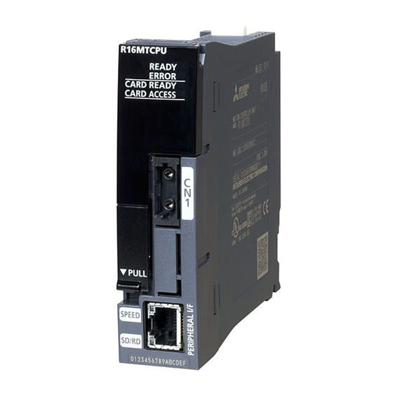
Mitsubishi Electric MELSEC iQ-R16MTCPU Manuals
Manuals and User Guides for Mitsubishi Electric MELSEC iQ-R16MTCPU. We have
4
Mitsubishi Electric MELSEC iQ-R16MTCPU manuals available for free PDF download: Programming Manual
Mitsubishi Electric MELSEC iQ-R16MTCPU Programming Manual (482 pages)
MELSEC iQ-R Series, Positioning Control
Brand:
Mitsubishi Electric
| Category:
Controller
| Size: 4.1 MB
Table of Contents
3
Safety Precautions
11
Conditions of Use for the Product
11
Introduction
12
Table of Contents
17
Relevant Manuals
18
Terms
19
Manual Page Organization
22
Chapter 1 Positioning Control By the Motion Cpu
22
Positioning Control By the Motion CPU
22
Parameters and Programs Used for Positioning Control
23
Starting a Servo Program
23
Direct Positioning Start From the PLC CPU
23
JOG Operation
23
Manual Pulse Generator Operation
24
Chapter 2 Positioning Dedicated Signals
26
Internal Relays
29
Axis Status
39
Axis Command Signals
48
Command Generation Axis Status
51
Command Generation Axis Command Signal
54
Synchronous Encoder Axis Status
55
Synchronous Encoder Axis Command Signal
56
Output Axis Status
58
Output Axis Command Signal
60
Synchronous Control Signal
62
Synchronous Analysis Complete Signal
64
Synchronous Control Start Signal
66
Synchronous Analysis Request Signal
68
Machine Common Command Signals
69
Machine Command Signals
71
Machine Status
73
Common Devices
90
Data Registers
93
Axis Monitor Devices
106
JOG Speed Setting Registers
108
Servo Input Axis Monitor Device
110
Servo Input Axis Control Device
112
Command Generation Axis Monitor Device
115
Command Generation Axis Control Device
117
Synchronous Encoder Axis Monitor Device
119
Synchronous Encoder Axis Control Device
120
Output Axis Monitor Device
123
Output Axis Control Device
130
Machine Control Device
132
Machine Monitor Device
136
G-Code Control Common Command Signal
137
G-Code Control Common Control Device
138
G-Code Control Common Status
139
G-Code Control Common Monitor Device
140
G-Code Control Line Command Signal
141
G-Code Control Line Control Device
142
G-Code Control Line Status
144
G-Code Control Line Monitor Device
148
G-Code Control Line Monitor Device (Expansion)
153
G-Code Control Axis Status
155
G-Code Control Axis Monitor Device
157
Common Devices
163
Motion Registers (#)
164
Monitor Devices 2 of Each Axis
167
Special Relays (SM)
167
Special Registers (SD)
168
Chapter 3 Parameters for Positioning Control
168
Parameters Used By the Motion CPU
170
Indirect Setting Method By Devices for Parameters
170
Fixed Parameters
171
Unit Setting
171
Number of Pulses Per Rotation/Travel Value Per Rotation
174
Backlash Compensation Amount
174
Upper/Lower Stroke Limit Value
176
Command In-Position Range
176
Speed Control 10 X Multiplier Setting for Degree Axis
180
Home Position Return Data
181
Home Position Return Direction
182
Home Position Return Method
182
Home Position Address
182
Home Position Return Speed
182
Creep Speed
183
Travel Value After Proximity Dog ON
184
Parameter Block Setting
185
Home Position Return Retry Function/Dwell Time at the Home Position Return Retry
186
Home Position Shift Amount/Speed Set at the Home Position Shift
187
Torque Limit Value at the Creep Speed
187
Operation Setting for Incompletion of Home Position Return
189
Setting Items for Home Position Return Data
190
JOG Operation Data
191
External Signal Parameter
194
Expansion Parameters
195
Positive Direction Torque Limit Value Monitor Device/Negative Direction Torque Limit Value Monitor Device
196
Acceleration/Deceleration Time Change Parameter
197
Servo Motor Maximum Speed Check Parameter
199
ABS Direction in Degrees Device
203
Speed-Torque Control Data
205
Control Mode Switching Request Device
205
Control Mode Setting Device
205
Speed Limit Value at Speed-Torque Control
205
Torque Limit Value at Speed-Torque Control
205
Speed Command Device
206
Command Speed Acceleration Time, Command Speed Deceleration Time
206
Torque Command Device
207
Command Torque Time Constant (Positive Direction), Command Torque Time Constant (Negative Direction)
208
Speed Initial Value Selection at Control Mode Switching
208
Torque Initial Value Selection at Control Mode Switching
208
Invalid Selection During Zero Speed at Control Mode Switching
209
Pressure Control Data
210
Pressure Control Selection
210
Feed/Dwell Startup Device
210
Dwell Forced Switching Device
210
Pressure Release Startup Device
210
Pressure Command Reference
210
Speed Limit Reference
211
Abnormal Pressure Setting Time
211
Mode Reset Selection After Passing Dwell Time
211
Pressure Profile Start Device
211
Pressure Control Status Device
211
Feed Execution Point Device
211
Dwell Execution Point Device
212
Override Data
212
Override Ratio Setting Device
213
Vibration Suppression Command Filter Data
214
Vibration Suppression Command Filter 1
215
Vibration Suppression Command Filter 2
215
Feed Current Value Monitor Device After Filter
215
Command Output Complete Signal After Filter
216
Servo Parameters
217
Parameter Block
219
Interpolation Control Unit
220
Speed Limit Value, Acceleration Time, Deceleration Time and Rapid Stop Deceleration Time
222
S-Curve Ratio
223
Advanced S-Curve Acceleration/Deceleration
235
Torque Limit Value
235
Deceleration Processing On STOP Input
236
Allowable Error Range for Circular Interpolation
236
Bias Speed at Start
238
Chapter 4 Servo Programs for Positioning Control
238
Servo Program Composition Area
238
Servo Program Composition
240
Servo Instructions
244
Positioning Data
250
Setting Method for Positioning Data
250
Setting Method for Direct Setting By Numerical Values
250
Indirect Setting Method By Devices
252
Chapter 5 Positioning Control
252
Basics of Positioning Control
252
Positioning Speed
253
Positioning Speed at the Interpolation Control
257
Control Units for 1 Axis Positioning Control
258
Control Units for Interpolation Control
259
Control in the Control Unit "Degree
261
Stop Processing and Restarting After Stop
268
Acceleration/Deceleration Processing
272
Axis Linear Positioning Control
275
Axes Linear Interpolation Control
278
5.4 3 Axes Linear Interpolation Control
282
5.5 4 Axes Linear Interpolation Control
285
Auxiliary Point-Specified Circular Interpolation Control
289
Radius-Specified Circular Interpolation Control
293
Central Point-Specified Circular Interpolation Control
297
Helical Interpolation Control
298
Circular Interpolation Specified Method By Helical Interpolation
311
Axis Fixed-Pitch Feed Control
314
Fixed-Pitch Feed Control Using 2 Axes Linear Interpolation
317
Fixed-Pitch Feed Control Using 3 Axes Linear Interpolation
320
Speed Control (I)
323
Speed Control (II)
326
Speed/Position Switching Control
326
Speed/Position Switching Control Start
332
Re-Starting After Stop During Control
336
Speed Control with Fixed Position Stop
340
Continuous Trajectory Control
343
Specification of Pass Points By Repetition Instructions
347
Speed-Switching By Instruction Execution
350
Axis Continuous Trajectory Control
353
To 4 Axes Continuous Trajectory Control
357
Continuous Trajectory Control for Helical Interpolation
362
Pass Point Skip Function
364
FIN Signal Wait Function
371
Position Follow-Up Control
375
High-Speed Oscillation
377
Simultaneous Start
379
Home Position Return
380
Servo Program for Home Position Return
382
Home Position Return By the Proximity Dog Method 1
384
Home Position Return By the Proximity Dog Method 2
386
Home Position Return By the Count Method 1
387
Home Position Return By the Count Method 2
388
Home Position Return By the Count Method 3
390
Home Position Return By the Data Set Method 1
391
Home Position Return By the Data Set Method 2
392
Home Position Return By the Data Set Method 3
393
Home Position Return By the Dog Cradle Method
396
Home Position Return By the Stopper Method 1
397
Home Position Return By the Stopper Method 2
398
Home Position Return By the Limit Switch Combined Method
400
Home Position Return By the Scale Home Position Signal Detection Method
402
Home Position Return By the Dogless Home Position Signal Reference Method
407
Home Position Return By the Driver Home Position Return Method
408
Home Position Return Retry Function
411
Home Position Shift Function
414
Condition Selection of Home Position Set
415
Current Value Change
417
Chapter 6 Manual Control
417
JOG Operation
417
Individual Start
420
Simultaneous Start
422
Manual Pulse Generator Operation
427
Chapter 7 Auxiliary and Applied Functions
427
M-Code Output Function
429
Backlash Compensation Function
430
Torque Limit Function
432
Skip Function in Which Disregards Stop Command
433
Speed-Torque Control
434
Operation of Speed-Torque Control
447
Acceleration/Deceleration Time Change Function
452
Pressure Control
453
System Configuration
454
Outline of Pressure Control
455
Pressure Profile
459
Feed/Dwell Operation
461
Pressure Release Operation
461
Operation By Stroke Limit
461
Using Point No. to Substitute M-Code
462
Pressure Control Settings
463
Mode Reset After Passing Dwell Time
463
Stop Causes During Pressure Control Mode
464
Override Function
469
Vibration Suppression Command Filter
469
Vibration Suppression Command Filter Operation
472
Precautions When Using Vibration Suppression Command Filter
475
Appendices
475
Appendix 1 Processing Times of the Motion CPU
478
Revisions
479
Warranty
480
Trademarks
Advertisement
Mitsubishi Electric MELSEC iQ-R16MTCPU Programming Manual (460 pages)
MELSEC iQ-R Series Motion Controller
Brand:
Mitsubishi Electric
| Category:
Controller
| Size: 4.13 MB
Table of Contents
3
Safety Precautions
11
Conditions of Use for the Product
11
Introduction
12
Table of Contents
17
Relevant Manuals
18
Terms
19
Manual Page Organization
22
Chapter 1 Multiple Cpu System
22
Multiple CPU System
22
Overview
23
Restrictions On Multiple CPU Systems Using Motion Cpus
25
Module Control with Motion Cpus
32
Setting Operation for Multiple CPU System
32
Setting Operation for CPU Module Stop Error
32
Multiple CPU Synchronous Startup Setting
32
Clock Synchronization Between Multiple CPU
33
Data Communication Between CPU Modules in the Multiple CPU System
33
Used Memory
35
Data Communication By Refreshing at Motion Cpus
40
Fixed Scan Data Transmission Section Over Check
41
Inter-Module Synchronization Function
49
Relationship Between Fixed Scan Communication and Inter-Module Synchronization
50
Control Instruction From PLC CPU to Motion CPU
51
Chapter 2 Common Parameters
51
Parameters Used By the Motion CPU
54
R Series Common Parameter
55
System Parameter
57
CPU Parameter
60
Module Parameter
61
Motion CPU Common Parameter
63
Basic Setting
66
Servo Network Setting
72
Manual Pulse Generator Connection Setting
73
Motion CPU Operating Status
73
Initial Processing
75
RUN/STOP Status Control
77
Chapter 3 Devices
77
Device List
79
Devices That Can Be Used with Each Function
81
User Device
81
Input (X)
81
Output (Y)
81
Internal Relay (M)
81
Link Relay (B)
81
Annunciator (F)
82
System Device
82
Special Relay (SM)
82
Special Register (SD)
82
CPU Buffer Memory Access Device
83
Module Access Device
83
Constants
84
Device Setting
84
Device Assignment Method
86
Device Points Setting
88
Latch Function
90
Chapter 4 Auxiliary and Applied Functions
90
Limit Switch Output Function
90
Operations
92
Limit Output Data Setting
96
External Input Signal
96
External Signal
97
High-Speed Input Request Signal
102
Mark Detection Function
103
Operations
104
Mark Detection Setting
110
Servo ON/OFF
111
Follow Up Function
112
Absolute Position System
114
Synchronous Control Absolute Position System
114
Saving and Recovering Backup Data
115
Clock Function
116
File Transfer Function
120
File Transmission at Boot Function
120
File Transmission at Boot Files
124
File Transmission at Boot Procedure
125
Operation When Security Function Is Set
127
File Transmission Via FTP Server
130
Parameter Change Function
132
Parameters Used with Parameter Change
162
Mixed Operation Cycle Function
165
Control Details
168
Precautions During Control
171
Chapter 5 Functions Used with Sscnet Communication
171
Servo Parameter Management
171
Transmission of Servo Parameters
173
Servo Parameter Read/Change Function
175
Optional Data Monitor Function
177
Optional Data Monitor Setting
182
Example of Using Transient Commands
185
SSCNET Control Function
186
Connect/Disconnect Function of SSCNET Communication
189
Amplifier-Less Operation Function
193
Virtual Servo Amplifier Function
195
Driver Communication Function
195
Control Details
196
Precautions During Control
199
Servo Parameter
200
Connection of SSCNETIII/H Head Module
200
System Configuration
201
SSCNETIII/H Head Module Parameters
206
Data Operation of Intelligent Function Module By Motion SFC Program
206
Data of Refresh Device
206
Precautions When Using SSCNETIII/H Head Module
207
Connection of Sensing Module
207
System Configuration
208
Sensing Module Parameters
217
Data of Refresh Device
218
Link Data (Station Mode)
240
Link Data (Axis Mode)
241
Sensing Module Functions (Station Mode)
245
Sensing Module Functions (Axis Mode)
252
Errors Detected By Sensing Module
252
Precautions When Using Sensing Module
253
Compatible Devices with SSCNETIII(/H)
253
Servo Driver VCII Series/Vph Series Manufactured By CKD Nikki Denso Co., Ltd
263
Inverter FR-A700 Series
270
Inverter FR-A800 Series
276
Optical Hub Unit
281
Alphastep/5-Phase Stepping Motor Driver Manufactured By ORIENTAL MOTOR Co., Ltd
288
IAI Electric Actuator Controller Manufactured By IAI Corporation
295
Chapter 6 Communication Functions
295
Communication Function List
296
Security Function
296
File Password
298
Software Security Key Authentication
303
IP Filter Function
304
Remote Operation
304
Remote RUN/STOP
306
Communication Function Via PERIPHERAL I/F
306
Direct Connection
309
Connection Via HUB
313
Vision System Connection Function
317
Vision System Parameter Setting
326
Flow of Vision System Control
327
Sample Program
330
Test Mode
330
Test Mode Specifications
331
Differences Between Normal Operation and Test Operation
331
Parameters Used During Test Mode
332
Test Mode Transition/Cancellation
333
Stop Processing of Axes Operating in Test Mode
334
Positioning Control Monitor Function
334
Scroll Monitor
335
Current Value History Monitor
336
Speed Monitor
337
Label Access From External Devices
339
Chapter 7 Digital Oscilloscope
339
Features
339
Function Overview
340
Digital Oscilloscope Specifications
341
Digital Oscilloscope Operating Procedure
341
Sampling Settings File
342
Sampling Functions
342
Sampling Type
342
Sampling Start Settings
342
Sampling Interval
343
Sampling Target
343
Trigger Settings
345
Saving Sampling Results
346
Digital Oscilloscope Status
347
Digital Oscilloscope Errors
348
Chapter 8 Motion Cpu Memory Structure
348
Memory and Files
348
Standard ROM/SD Memory Card Specifications
349
File Handling Precautions
350
Stored Files
352
SD Memory Card
352
SD Memory Card Handling
352
SD Memory Card Forced Stop
354
Memory Initialization
355
Installing the Operating System Software
356
Installation Procedure Using MT Developer2
357
Installation Procedure Using SD Memory Card
359
Add-On Function
360
Add-On Module Structure
360
Installing Add-On Library
360
Add-On Function Load Error
360
Add-On Library License Authentication
368
Chapter 9 Ras Functions
368
Self-Diagnostics Function
368
Self-Diagnostics Timing
368
Error Checking Methods
370
Operations at Error Detection
371
Cancelling Errors
372
Safety Functions
372
Processing Time Monitor and Check
375
Event History Function
375
Event History Settings
375
Saving Event History
377
Viewing the Event History
377
Clearing the Event History
378
Appendices
378
Appendix 1 Error Codes
378
Error Codes System
379
Operations at Error Occurrence
379
Cancelling Errors
379
Error Codes Stored Using the Motion CPU
381
Warning (0800H to 0FFFH)
387
Minor Error (1000H to 1FFFH)
400
Minor Error (SFC) (3100H to 3BFFH)
413
Moderate Error (2000H to 3BFFH)
422
Major Error (3C00H to 3FFFH)
423
Add-On License Error Details Codes
424
Appendix 2 Event List
424
Guide for Reference of Event List
425
Event History List
428
Appendix 3 Special Relays
433
Appendix 4 Special Registers
456
Revisions
457
Warranty
458
Trademarks
Mitsubishi Electric MELSEC iQ-R16MTCPU Programming Manual (250 pages)
Motion Controller, G-Code Control, MELSEC iQ-R Series
Brand:
Mitsubishi Electric
| Category:
Controller
| Size: 1.87 MB
Table of Contents
3
Safety Precautions
11
Conditions of Use for the Product
11
Introduction
12
Table of Contents
16
Relevant Manuals
17
Terms
18
Manual Page Organization
21
Chapter 1 Overview
21
G-Code Control Overview
22
Performance Specifications
23
G-Code Control Add-On Library Configuration
23
G-Code Control Add-On Library
23
Files Size/Memory Usage
24
Chapter 2 Starting Up the System
24
Starting Up the G-Code Control System
26
2.2 License Authentication of G-Code Control Add-On Library
26
Control Cycle of G-Code Control
27
G-Code Control System Device Assignment Method
27
G-Code Control System Start/End
28
G-Code Control System Stop Operation
29
Immediate Stop
29
Deceleration Stop
30
Chapter 3 G-Code Control Dedicated Signals
31
G-Code Control Common Command Signal
32
G-Code Control Common Control Device
33
G-Code Control Common Status
34
G-Code Control Common Monitor Device
36
G-Code Control Line Command Signal
39
G-Code Control Line Control Device
40
G-Code Control Line Status
47
G-Code Control Line Monitor Device
57
G-Code Control Line Monitor Device (Expansion)
63
G-Code Control Axis Status
65
G-Code Control Axis Monitor Device
69
Internal Relay (M)/Data Register (D) Availability
69
Internal Relays
72
Data Registers
74
Chapter 4 G-Code Control Parameters
75
G-Code Control System Parameter
78
Line Basic Setting
78
Modal Initial Setting
78
Control Setting
80
Override Setting
81
Plane Composition
81
Normal Line Control
82
Auxiliary Function
82
Polar Coordinate Interpolation
82
High-Accuracy Control
84
G-Code Control Axis Parameter
85
Line Axis Information
86
Stored Stroke Limit
87
Speed/Time Constant
88
Rotation Axis Information
89
Tandem Function
90
High-Accuracy Control
91
G-Code Control Processwork Parameter
91
Tool Radius Compensation
92
Tool Compensation Data
92
Workpiece Coordinate Offset
92
Program Coordinate Rotation
93
Chapter 5 G-Code Control Programs
93
G-Code Control Program Composition
94
G-Code Program Format
96
Fetching G-Code Program Files
96
Fetching G-Code Program File During Operation
97
Pre-Read Buffer
98
Decimal Point Input
99
Coordinate System
99
Basic Machine Coordinate System
99
Work Coordinate System
100
Local Coordinate System
100
Automatic Coordinate System Setting
100
Coordinate System for Rotation Axes
101
G-Code
101
G-Code List
102
Modal/Unmodal
102
G-Code Priority
105
G00: Positioning (Fast Forward)
106
G01: Linear Interpolation
107
G02: Circular Interpolation CW (Center Specified)
109
G03: Circular Interpolation CCW (Center Specified)
111
G02: Circular Interpolation CW (R-Specified)
113
G03: Circular Interpolation CCW (R-Specified)
115
G04: Dwell (Time Specified)
116
G09: Exact Stop Check
117
G12.1: Polar Coordinate Interpolation Mode Start
122
G13.1: Polar Coordinate Interpolation Mode Cancel
123
G17 to G19: Plane Selection
124
G38: Tool Radius Compensation Vector Setting
126
G39: Tool Radius Compensation Corner Arc
128
G40: Tool Radius Compensation Cancel
129
G41: Tool Radius Compensation - Left
130
G42: Tool Radius Compensation - Right
131
G40.1: Normal Line Control Cancel
132
G41.1: Normal Line Control - Left ON
133
G42.1: Normal Line Control - Right ON
134
G43: Tool Length Compensation (+)
136
G44: Tool Length Compensation
138
G49: Tool Length Compensation Cancel
139
G52: Local Coordinate System Setting
143
G53: Basic Machine Coordinate System Selection
144
G54 to G59: Work Coordinate System 1 Selection to Work Coordinate System 6 Selection
147
G61: Exact Stop Check Mode
148
G61.1: High-Accuracy Control Mode
149
G62: Automatic Corner Override
152
G64: Cutting Mode
153
G68: Program Coordinate Rotation Mode Start
158
G69: Program Coordinate Rotation Mode Cancel
159
G90: Absolute Value Command
161
G91: Incremental Value Command
163
G94: Feed Per Minute (Non-Synchronized Feed)
164
M-Code
165
M00: Program Stop
166
M01: Optional Stop
167
M02: Program End
168
M30: Program End
169
Chapter 6 Auxiliary and Applied Functions
169
Relationship Between G-Code Control and Each Function
171
Auxiliary Function (M Function)
171
M-Code Output
173
Auxiliary Function Complete
175
Feed Function
175
Fast Forward Speed
176
Cutting Feed Speed
177
Feed Speed Specification and the Effects On Each Control Axis
180
Deceleration Check
184
Tool Compensation Function
184
Tool Compensation
185
Tool Length Compensation
185
Tool Radius Compensation
209
Operation Supporting Functions
209
Automatic Operation Start (Cycle Start)
210
Automatic Operation Hold (Feed Hold)
211
Reset
212
Single Block
213
Normal Line Control Function
226
High-Accuracy Control
228
Acceleration/Deceleration before Interpolation
230
Optimum Speed Control
236
Vector Accuracy Interpolation
236
Arc Entrance/Exit Speed Control
237
Tandem Function
238
G-Code Program Operation By GOT
238
GOT Program Input/Output Function
238
GOT Program Edit Function
239
Appendices
239
Appendix 1 G-Code Control Error/G-Code Control Event Details Codes
239
G-Code Control Error Details Codes
244
Add-On License Error Details Codes
245
Appendix 2 G-Code Control Event Details Codes
245
G-Code Control Event Details Codes
246
Revisions
247
Warranty
248
Trademarks
Advertisement
Mitsubishi Electric MELSEC iQ-R16MTCPU Programming Manual (124 pages)
MELSEC iQ-R series Motion Controller (Machine Control)
Brand:
Mitsubishi Electric
| Category:
Controller
| Size: 1.59 MB
Table of Contents
3
Safety Precautions
11
Conditions of Use for the Product
11
Introduction
12
Table of Contents
14
Relevant Manuals
15
Terms
16
Manual Page Organization
19
Chapter 1 Overview
19
Machine Control Overview
21
Performance Specifications
22
Chapter 2 Starting Up the System
22
Starting Up the Machine Control System
23
Machine Control System Positioning Controls
23
Machine Program Operation Start
23
Machine JOG Operation
24
Machine Control System Stop Operation
24
Machine Control System Device Assignment Method
25
Chapter 3 Machines
25
Overview of a Machine
25
Machine Position
27
Chapter 4 Machine Control Dedicated Signals
28
Internal Relays
28
Machine Common Command Signals
29
Machine Command Signals
34
Machine Status
37
Data Registers
37
Machine Control Device
40
Machine Monitor Device
49
Chapter 5 Machine Control Parameters
49
Machine Common Parameter
49
Point Block Setting
50
Machine Parameter
52
Machine Basic Setting
52
Joint Axis Structure
52
Arm Length Setting
52
Machine Speed Setting
53
XYZ Stroke Limit Setting
53
Base Transformation (Install Coordinate Offset)
55
Tool Transformation
55
Option Setting a
55
Option Setting B
56
Motion Control Parameter of Machine Configuration Axes
56
Axis Setting Parameter
57
Chapter 6 Machine Control Data
57
Machine Positioning Data
65
Point Block Data
65
Structure of Point Block Data
68
Chapter 7 Positioning Control
68
Basics of Positioning Control
68
Positioning Speed
69
Positioning Speed at the Interpolation Control
73
Interpolation Operation and Acceleration/Deceleration Processing
75
Control Units During Machine Control
76
Control When Control Unit Is "Degree
77
Stop Processing and Restarting After Stop
77
Operation at Home Position Return Incomplete
78
Continuous Trajectory Control (Machine Program Operation)
78
PTP Control
79
Linear Interpolation/Joint Interpolation
80
Circular Interpolation
83
Sequential Coordinate Command Control
87
Speed Switching During Instruction
88
Chapter 8 Manual Control
88
JOG Operation
88
Manual Pulse Generator Operation
89
Machine JOG Operation
92
Chapter 9 Auxiliary and Applied Functions
92
Relationship Between Machine Control and Each Function
93
Proximity Pass Function
93
JOINT Remaining Distance Method (End Point Distance)
101
Speed Restriction Function
101
Joint Interpolation Speed Limit
102
Servo Motor Maximum Speed Check
103
Base/Tool Transformation Change Function
106
Wait-On/Off
108
Point Arrival Notification
110
Appendices
110
Appendix 1 Sample Program of Machine Control
115
Appendix 2 Machine Control Error Details Codes
115
Machine Error Details Codes
119
Appendix 3 Machine Control Event Details Codes
119
Machine Event Details Codes
120
Revisions
121
Warranty
122
Trademarks
Share and save
Advertisement
Related Products
Mitsubishi Electric MELSEC iQ-R16ENCPU
Mitsubishi Electric MELSEC iQ-R16CPU
Mitsubishi Electric MELSEC iQ-R16PSFCPU
Mitsubishi Electric MELSEC iQ-R16PCPU
Mitsubishi Electric MELSEC iQ-R16SFCPU
Mitsubishi Electric MELSEC iQ-R120ENCPU
Mitsubishi Electric MELSEC iQ-R120CPU
Mitsubishi Electric MELSEC iQ-R120PCPU
Mitsubishi Electric MELSEC iQ-R120PSFCPU
Mitsubishi Electric MELSEC iQ-R120SFCPU
Mitsubishi Electric Categories
Air Conditioner
Controller
Projector
Inverter
Monitor
More Mitsubishi Electric Manuals
×
Login
Sign In
OR
Sign in with Facebook
Sign in with Google
×
Upload manual
Upload from disk
Upload from URL