
Related Manuals for Micros Systems Eclipse


Summary of Contents for Micros Systems Eclipse
-
Page 1: Setup Guide
® Systems, Inc. PC Workstation Eclipse Setup Guide Copyright 2001, 2002, 2004 By MICROS Systems, Inc. Columbia, Maryland USA All Rights Reserved Part Number 100016-113 (4th Edition) -
Page 2: Declarations
Although the best efforts are made to ensure that the information contained in this manual is complete and correct, MICROS Systems, Inc. makes no warranty of any kind with regard to this material, including but not limited to the implied warranties of marketability and fitness for a particular purpose. -
Page 3: Table Of Contents
Eclipse System Unit ......... . . 1-2 Eclipse LCD/Touchscreen Head ....... . . 1-3 12.1”... - Page 4 Setting the USB Floppy Disk Drive to Boot the Workstation ..1-19 Connecting the Eclipse to a LAN ......1-20 Operating the Eclipse .
- Page 5 Disassembling the Eclipse ........
- Page 6 Re-assembling the Eclipse ........
- Page 7 Table Of Contents Cash Drawer, Low Profile ........A-6 Connector and Cable Diagrams Front Panel Connectors .
- Page 8 Table of Contents viii...
- Page 9 In this preface, you’ll find information about this manual. Refer to the preface if you have questions about the organization, conventions, or contents of this manual. In this section Why Read This Manual?.............. x How This Manual Is Organized ..........xi Notation Conventions ..............xii PCWS Eclipse Setup Guide...
-
Page 10: Why Read This Manual
To use the PCWS with a specific application, consult the Related Manuals section listed below. Who Should Use This Manual? This manual is intended for qualified service personnel who have experience with upgrading and configuration of personal computer based systems. PCWS Eclipse Setup Guide... -
Page 11: How This Manual Is Organized
How This Manual is Organized This manual is divided into five chapters, briefly discussed below. Chapter 1 describes each of the Eclipse components and shows how to assemble them into a complete workstation. The chapter also provides specifications, care and handling instructions, and information on how to connect peripherals to the Front I/O Panel. -
Page 12: Notation Conventions
STATIC SENSITIVE DEVICES This symbol indicates that specific ESD handling procedures are required. Document Design and Production Desktop Publishing: Adobe FrameMaker. Imaging: Nikon Coolpix 990. Image processing: Adobe Photoshop, Paint Shop Pro. Line drawings: Corel Draw! PCWS Eclipse Setup Guide... - Page 13 Chapter 1 What Is The Eclipse Workstation? In this chapter The System ....................1-2 Features......................1-6 Specifications....................1-8 The I/O Panel ..................... 1-14 Connecting Peripherals to the Eclipse ............1-18 Operating the Eclipse................. 1-21 PCWS Eclipse Setup Guide...
-
Page 14: Eclipse System Unit
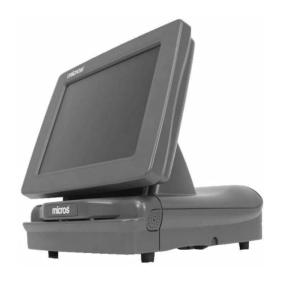
The following section describes the PCWS Eclipse Workstation and components. The Eclipse will be available with two LCD/Touchscreen Head selections. Eclipse System Unit The Eclipse System Unit, shown in Figure 1-1, consists of a plastic cover and pedestal which fits over a metal chassis. Figure 1-1: The Eclipse System Unit The system unit contains the power supply, system board, and optionally, a single desktop style IDE hard disk and 2x20 customer display. -
Page 15: Eclipse Lcd/Touchscreen Head
The System Eclipse LCD/Touchscreen Head The PCWS Eclipse is now available with two display configurations. The standard display is based on a 12.1” TFT LCD Panel, and a new optional display is available, based on a 15” TFT LCD Panel. Each component is detailed below. - Page 16 ELO Touchsystems 15” LCD Monitor/Touchscreen combination. It is fastened directly to the pedestal hinge. The Eclipse front panel DVI connector supplies all LCD, touchscreen, backlight control and data signals as well as +12V to the LCD/Touchscreen Head. Firmware modifications allow this display to emulate the 12”...
-
Page 17: The Front Cover And Magnetic Card Reader
Figure 1-4: The Eclipse Front Cover The magnetic card reader can be easily removed and replaced in just a few minutes. The entire reader assembly attaches to the Eclipse with a modular connector, further allowing the unit to be quickly and easily replaced. -
Page 18: Features
Features Features Expansion Capabilities The Eclipse does not contain ISA or PCI slots. Expansion takes the form of a Type II PCMCIA Cardbus Slot, USB port(s), and three available serial ports. PCMCIA CardBus Slot The Eclipse Workstation includes a single Type II 32-bit PCMCIA CardBus Slot. -
Page 19: Disk-On-Chip
• Sound Max Audio Drivers support the Analog Devices Codec. Built-in Speakers The Eclipse includes a pair of water resistant speakers mounted on each side of the front connector panel. Disk-On-Chip The Eclipse system board supports the M-Systems Disk On Chip (DOC) device. A Disk On Chip consists of a block of Flash EPROM, residing behind firmware that when supported by the workstation’s BIOS, looks like a bootable or non-bootable... -
Page 20: Specifications
What Is The Eclipse Workstation? Specifications Specifications The PCWS Eclipse workstation conforms to the following specifications. Specification Parameters Processors Celeron C850MHz or Pentium III 1GHz Processor Socket Socket 370 Cache Celeron = 128K L2 cache, Pentium III = 256K L2 cache, Display(s) 12.1”... -
Page 21: Approvals
18lb /w Hard Disk and Customer Display Case Material ABS Plastic Physical Dimensions See Appendix A Approvals The Eclipse Workstation meets the following safety and environmental certifications. Certification Number Comments Underwriters Laboratory, Inc., Standard for UL-1950 Safety of Information Technology Equipment... - Page 22 What Is The Eclipse Workstation? Specifications Certification Number Comments International Electrotechnical Commission, IEC801-2 Electromagnetic Compatibility for IEC801-3 27-500MHz, 3V/cm Industrial-Process Measurement and Control (UNMOD) Equipment IEC801-4 0.5kV SIGNAL LINES, 1.0kV AC Mains 1-10 PCWS Eclipse Setup Guide...
-
Page 23: Care And Handling
Liquid spillage can cause damage to the circuits in the unit. Do not place the equipment near food preparation areas, dish racks, or water stations. The Eclipse LCD head includes a gasket seal around the touchscreen which may afford some protection from liquid spillage. -
Page 24: Electrostatic Discharge (Esd)
However, tile or anti-static carpet should still be employed in areas near the workstation. Temperature and Humidity The PCWS Eclipse operating temperature is between 40°F and 113°F (5°C to 45°C), if the Celeron C850 MHz processor is installed. The PCWS Eclipse operating temperature is between 40°F and 104°F (5°C to 40°C), if the Pentium III 1GHz processor is installed. -
Page 25: Magnetic Card Reader
What Is The Eclipse Workstation? Care and Handling Magnetic Card Reader Depending on how much they are used, magnetic card readers may require periodic cleaning. Cleaning kits are available from a variety of sources. Be sure to follow the instructions supplied with the cleaning kits. -
Page 26: The I/O Panel
Working from left to right, descriptions for each connector follows. P13 - Mic In - Line Out The Microphone input jack allows you to connect a microphone to the Eclipse and record sound clips. The Line Out jack is capable of driving most external powered speakers. -
Page 27: The Modular Connector Block
What Is The Eclipse Workstation? The I/O Panel The Modular Connector Block Figure 1-6 shows the bank of six modular connectors located on the Eclipse Front I/O Panel, described below. Figure 1-6: The Front Panel Modular Connectors 10/100 Ethernet The Eclipse system board includes a PCI based 10/100 Ethernet controller with a 10BaseT connector on the front connector panel. -
Page 28: Internal Speakers
USB is based on a tiered star topology that runs at a data rate of up to 12Mb per second. All USB devices are Plug and Play compatible, and can be connected to the Eclipse when power is on. This means that each device can be recognized without rebooting the workstation. -
Page 29: Cash Drawers 1 And 2
In late 2004, the internal power supply to front panel cable has been modified to include a 4A, 125V Axial Lead fuse in series with the +24VDC line. Figure 1-7: Connecting the Printer Power Cable to the Eclipse Auxiliary Power Connector This connector appears in units assembled after September 2001. -
Page 30: Connecting Peripherals To The Eclipse
When installed with a copy of Windows 95 where the USB upgrade (USBSUPP.EXE) has not been applied, the USB Floppy Disk Drive appears as the A: drive in Explorer. This is how the Windows 95 version of the Eclipse hard disk image is supplied. -
Page 31: Setting The Usb Floppy Disk Drive To Boot The Workstation
If the workstation refuses to boot from the USB Floppy Disk Drive, and the Eclipse is running BIOS version 1.00.22 or later, check the Boot Order Sequence in BIOS Setup. -
Page 32: Connecting The Eclipse To A Lan
FD (Full Duplex) When the Link LED is ON, the FD LED indicates if the Eclipse is connected to a full or half-duplex LAN. The operation of the Link and FD LEDs is summarized in the table below. -
Page 33: Operating The Eclipse
On the following pages, you’ll find several procedures for operating the Eclipse. Turning the Workstation On and Off The upper half of Figure 1-10 shows the location of the Eclipse Power Switch. The lower half of the illustration shows the location of the power indicator visible only when the Front Cover is removed. -
Page 34: Using The Magnetic Card Reader
What Is The Eclipse Workstation? Operating the Eclipse Using the Magnetic Card Reader The card reader is mounted on the front cover of the workstation for easy access and service. Figure 1-11 shows that you can swipe a card in either direction, with the mag stripe facing down and towards the rear of the workstation. - Page 35 What Is The Eclipse Workstation? Operating the Eclipse The original 12.1” DSTN or TFT LCD/Touchscreen head (400497-001 or 400497-002) with a 3M MicroTouch Excalibur controller. The recent 12.1” LCD Head/Touchscreen (400497-003A) with the Hampshire TSHARC touchscreen controller. The 15” LCD/Touchscreen Head.
-
Page 36: Using The 15" Lcd/Touchscreen Head Controls
The Power On/Off button allows the 15” LCD/Touchscreen Head to be powered down independently of the Eclipse system unit. The On Screen Display menu provides access to brightness and contrast controls, and other display related functions. -
Page 37: Bios Setup Utility
BIOS Setup Utility The Phoenix BIOS Setup Utility provides a central location for configuring the Eclipse system board hardware. The BIOS Setup Utility is stored in Flash EPROM, so it is available even if a hard disk or operating system is not installed. -
Page 38: Starting The Phoenix Setup Utility/Checking The Micros Bios Version
This menu lets you set the system date and time, define the type of hard disk installed, and display the total amount of memory installed on the system board. Advanced This menu provides access to settings for the Eclipse COM ports, LPT port, and mag card reader. Power This menu provides access to the Eclipse power saving modes. -
Page 39: Boot
Starting the Phoenix Setup Utility/Checking the MICROS BIOS Version Boot This menu allows the user to determine the Eclipse boot device sequence. The boot device may be an external USB Floppy Disk Drive, internal IDE hard disk, network boot ROM, or optional Disk On Chip. -
Page 40: Main
The alternate setting, ECHS, could be used if you move a hard disk from a PCWS Ultra or other computer to the Eclipse and it refuses to boot. This problem is seen as a blinking cursor in the upper left corner of the LCD. -
Page 41: Primary Slave
PCMCIA and USB CD-ROM drives. Primary Slave [None] The Eclipse workstation supports a single IDE Hard disk internally, the Primary Master. However, if you have a dual-drive ATA/66 IDE ribbon cable with three connectors and a “Y” cable adapter to power both drives, set this field to [Auto], then reboot the workstation to allow the BIOS to detect the IDE device you have installed temporarily. -
Page 42: Pc Beep Mute
AC power failed. LAN Boot Function: [Disabled] The ability of the Eclipse to boot from a LAN or from the Disk On Chip is mutually exclusive. Thus, if a Disk On Chip is installed, and you must boot from the LAN, set this field to [Enabled]. -
Page 43: Advanced
BIOS Setup Utility Advanced Advanced This menu is a gateway to several sub-menus where you access many of the Eclipse hardware features including the peripheral ports. The default setting for each field are shown in [ ]. Several fields first appeared in BIOS Version 1.00.20, available only on the Micros web site. -
Page 44: Io Device Configuration
BIOS Setup Utility Advanced IO Device Configuration -> This sub-menu allows you to enable or disable the Eclipse’s six COM ports and single LPT port. Press [Enter] to view the following selections, described below. COM1: [Enabled - IO Addr=3F8, IRQ=4] This selection enables or disables the front panel DB9 serial connector. - Page 45 If the parallel port Mode is set to “ECP”, you must assign it either DMA Channel 1 or DMA Channel 3. DMA 1 is recommended. Magnetic Card Reader Mode [Special] This field determines how magnetic card data is processed by the Eclipse workstation. The selections are Magtek and Special. Magtek When Magtek mode is selected, card data is processed to appear as if it were entered through a PC keyboard.
-
Page 46: Local Bus Ide Adapter
When [Special] mode is enabled, card data is placed in a buffer unmodified, where it can be accessed through the Eclipse API. The API allows the application full access to mag card data and is typically used for credit card authorization applications. -
Page 47: Power
BIOS Setup Utility Power Power This menu provides access to the Eclipse System Board power saving features. Power savings are disabled by default. Power Savings: [Disabled] When set to [Disabled], power management features are turned off and will not function regardless of the other settings in this menu. -
Page 48: Boot
This allows you to install a USB floppy at any time and use it to boot the workstation without having to alter the boot sequence. 2-12 PCWS Eclipse Setup Guide... - Page 49 [M-Systems DiskOnChip (c)] field and pressing [Shift]-[+] once to move it to the top of the list. The Eclipse can boot directly from the DOC if you press the Micros Recovery Button, located on the front panel, and restart the workstation. Pressing this button sets a recovery bit in the CMOS RAM which is checked by the BIOS at each power up.
-
Page 50: Exit
If you have made any changes to CMOS settings, use this selection to ensure that the changes you made are saved in CMOS RAM. CMOS RAM is a type of non-volatile RAM whose content is protected by the Lithium coin cell on the Eclipse System Board. -
Page 51: Pcws Eclipse Hardware Configuration
Remove/Replace Power Supply..............3-16 Remove/Replace the Hard Disk..............3-18 Remove/Replace DIMMs ................3-20 Remove/Replace the System Processor............. 3-24 Installing a PCMCIA Card ................ 3-29 Installing a Disk On Chip ................3-32 Re-assembling the Eclipse ................. 3-36 PCWS Eclipse Setup Guide... -
Page 52: Disassembling The Eclipse
Figure 3-2 shows the bottom of the Eclipse chassis and points out the release points for the Front Cover. However, you need not stand the unit on end. Simply stand directly in front of the Eclipse, reach under the chassis and press these clips to loosen the front cover. - Page 53 PCWS Eclipse Hardware Configuration Disassembling the Eclipse As you remove the front cover, be sure to remove the card reader cable from the modular connector on the front panel. Figure 3-3. Set the front panel aside. Figure 3-3: Removing the Mag Card Reader Connector Remove the AC power cable.
- Page 54 PCWS Eclipse Hardware Configuration Disassembling the Eclipse Remove the 12.1” LCD/Touchscreen Head Rotate the LCD head to the position shown in Figure 3-5, and remove the thumbscrews. Figure 3-5: Removing the 12.1” LCD/Touchscreen Head Thumbscrews Lift the LCD head up about 1 or 2 inches then it pull forward.
- Page 55 PCWS Eclipse Hardware Configuration Disassembling the Eclipse Remove the two thumbscrews that fasten the system unit cover to the chassis by turning them in the direction shown in the Figure below. Figure 3-7: Remove the System Unit Cover Thumbscrews Remove the system unit cover. Lift the front of the cover from the chassis and...
- Page 56 PCWS Eclipse Hardware Configuration Disassembling the Eclipse Removing the Eclipse 15” LCD/Touchscreen Head The 15” LCD/Touchscreen Head assembly is not mounted to the pedestal with thumbscrews. A procedure for removing the 15” LCD/Touchscreen head is provided below. The MCR cover and DVI connector have already been removed.
- Page 57 Figure 3-10: Removing the System Unit Cover Latches Open the cover, placing it to the left. Figure 3-11 points out the major internal components of the Eclipse, which are described in more detail in the following pages. Figure 3-11: Eclipse System Unit - Cover Open...
-
Page 58: What's Inside
Figure 3-12: The Eclipse System Board - Chips STK3 - Socket 370 Processor Socket The Eclipse System Board includes a Zero Insertion Force (ZIF) Socket 370 Processor socket capable of supporting both the PPGA (Plastic Pin Grid Array) version of the Celeron and FC-PGA (Flip Chip-Pin Grid Array) version of the Pentium III Processor. -
Page 59: Intel© I810 Chipset
© Intel i810 Chipset The Eclipse system board is based on the Intel i810 chipset, which consists of three devices, the 82810 Graphics and Memory Controller Hub (GMCH), 82801AA IO Controller Hub (ICH), and the 82802 Firmware Hub (FWH). A brief description of each chip follows. - Page 60 PCWS Eclipse Hardware Configuration What’s Inside? 82802A Firmware Hub The 82802A version of the Firmware Hub contains 4M of Flash Memory divided into 8 64K blocks, each of which can be independently write protected. The Intel i810 chipset does not support the ISA bus. Thus, the Firmware Hub replaces the traditional Flash EPROM located on the ISA Bus.
-
Page 61: Dimm Sockets
What’s Inside? DIMM Sockets The Eclipse System Board includes a pair of Dual In Line Memory Module (DIMM) sockets that allow the workstation to support a maximum of 256M of PC100 SDRAM. Approved DIMMs are listed in the section on removing and replacing system memory. -
Page 62: Texas Instruments Pc1211 Pcmcia Controller
Texas Instruments PC1211 PCMCIA Controller This device resides on the PCI bus and provides an interface to the PCMCIA CardBus connector located on the left side of the Eclipse System Unit. Realtek RTL8139B 10/100 Ethernet Controller The RTL8139B is a highly integrated single-chip Fast Ethernet Controller coupled with a 10BaseT (IEEE 802.3) or 100BaseT (IEEE 802.3u) Ethernet transceiver. -
Page 63: System Board Connectors
PCWS Eclipse Hardware Configuration What’s Inside? System Board Connectors Figure 3-14, below shows the Eclipse System Board connectors. Figure 3-14: Eclipse System Board Connectors Details on removing and replacing internal components including the Power Supply, Hard Disk, Customer Display, Processor, Disk On Chip, and DIMMs can be found in the remaining pages of this chapter. -
Page 64: Remove/Replace The Customer Display
Remove/Replace the Customer Display This procedure describes how to remove and replace an existing customer display. Refer to page 3-2 to disassemble the Eclipse Workstation if you have not done so already. Examine Figure 3-15 and push on the rear display bracket at the three points indicated to release it from the chassis. - Page 65 PCWS Eclipse Hardware Configuration Remove/Replace the Customer Display Insert the customer display and bracket into the chassis slots as shown in Figure 3-17. Figure 3-17: Inserting the Customer Display Bracket into the Chassis Rotate the customer display bracket towards the chassis until it snaps into place.
-
Page 66: Remove/Replace Power Supply
PCWS Eclipse Hardware Configuration Remove/Replace Power Supply Remove/Replace Power Supply STATIC SENSITIVE DEVICES Always follow ESD procedures when replacing the power supply. Refer to page 3-2 to remove the cover if you have not done so already. If a hard disk is installed, lift the rear and remove the 4-conductor power connector. - Page 67 PCWS Eclipse Hardware Configuration Remove/Replace Power Supply Power supplies shipped since August 2001 include a universal input. However, if you see a red slide switch located near the AC input receptacle, it must be set to match the incoming AC voltage.
-
Page 68: Remove/Replace The Hard Disk
STATIC SENSITIVE DEVICES Always follow ESD procedures when handling the hard disk. Refer to page 3-2 to disassemble the Eclipse Workstation if you have not done so already. Lift the hard disk and remove the four-conductor power cable and multi-conductor data cable. - Page 69 PCWS Eclipse Hardware Configuration Remove/Replace the Hard Disk Figure 3-24: Installing the Hard Disk Data and Power Cables Install the foam ears on the hard disk. Place the hard disk in the bracket. To close the System Unit cover, see page 3-36.
-
Page 70: Remove/Replace Dimms
PC100 SDRAM +3.3V Unbuffered 700502-167 256M PC100 SDRAM +3.3V Unbuffered 700502-170 Figure 3-26: Recommended DIMM Part Numbers Purchasing DIMMs The Table shown in Figure 3-27 lists MICROS approved DIMMs for the Eclipse. Eclispe Approved DIMM List 128M 256M 700502-165 700502-166 700502-167... -
Page 71: Configuring Dimms
Install DIMMs in SKT1 first, then SKT2. You may install a single DIMM in either socket. Figure 3-28: Eclipse System Board DIMM Sockets Figure 3-29 shows a typical DIMM, pointing out the socket notches and the location of the Serial Presence Detect EEPROM. -
Page 72: Installing Dimms
Figure 3-30: Eclipse System Board DIMM Configuration Installing DIMMs Refer to page 3-2 to disassemble the Eclipse Workstation if you have not done so already. If you must remove a DIMM to install one with a larger capacity, see the following section on removing DIMMs. -
Page 73: Remove A Dimm
PCWS Eclipse Hardware Configuration Remove/Replace DIMMs Make sure each retaining clip is in the open position. Figure 3-31. Note the location of the notches on the DIMM edge connector, and the corresponding lands on the connector. Place the DIMM in the socket. Firmly press down on each end of the DIMM. -
Page 74: Remove/Replace The System Processor
Remove/Replace the System Processor The Celeron vs. the Pentium III Processor When the Eclipse entered production, it could be ordered with either a Celeron 366MHz processor in the Plastic Pin Grid Array (PPGA) package, or a Pentium III 700 MHz processor in the Flip-Chip Grid Array (FC-PGA) package. - Page 75 • Only the Intel Processor selections indicated in the table have been certified for use in the Eclipse across the stated operating temperatures, found in Chapter 1. Use other processor/heat sink combinations at your own risk. • The Intel i810 Chipset front side bus (FSB) is limited to 100MHz. Processors that require a 133MHz FSB are not supported.
- Page 76 PCWS Eclipse Hardware Configuration Remove/Replace the System Processor Press down on the hinged end to release the clip from the processor socket, then remove the heatsink. Figure 3-35: Removing the Heat Sink Clip Pull the release handle away from the socket, then rotate it 90 degrees to a vertical position as shown in the lower half of Figure 3-36.
- Page 77 PCWS Eclipse Hardware Configuration Remove/Replace the System Processor Before inserting a new processor, make sure the release lever is in the full upright position as shown in Figure 3-37. Note the orientation of Pin-1 on the Celeron or Pentium III processor as shown in Figure 3-37.
- Page 78 PCWS Eclipse Hardware Configuration Remove/Replace the System Processor Reattach the heatsink and fan assembly to the processor. Figure 3-38. This is best accomplished by attaching the clip to the rear of the socket first, then pushing on the front clip to lock it into place.
-
Page 79: Installing A Pcmcia Card
PCWS Eclipse Hardware Configuration Installing a PCMCIA Card Installing a PCMCIA Card Refer to page 3-2 and remove the system unit cover if you have not done so already. STATIC SENSITIVE DEVICES: Always follow ESD procedures when removing or installing a PCMCIA Card. - Page 80 PCWS Eclipse Hardware Configuration Installing a PCMCIA Card Insert the PCMCIA Card into the card bus cage. Figure 3-42 shows the location of the slots in the card cage. Figure 3-42: Installing a PCMCIA Adapter Figure 3-43, shows the knock-outs located on the cover plate. Remove these knock-outs as required to accommodate cables, dongles, or wireless antennas.
- Page 81 PCWS Eclipse Hardware Configuration Installing a PCMCIA Card With a nibbling tool or large hobby knife, remove material from the left side of the system unit cover where a cable must exit the workstation. Note the cover material is reduced at the points outlined in white.
-
Page 82: Installing A Disk On Chip
Installing a Disk On Chip This procedure describes how to install and configure the Optional Disk On Chip. Procedure: Refer to page 3-2 and remove the Eclipse system unit cover if you have not done so already. STATIC SENSITIVE DEVICES Always follow ESD procedures when handling and installing the Disk On Chip. - Page 83 PCWS Eclipse Hardware Configuration Installing a Disk On Chip The Disk On Chip socket is U33, located on the rear left corner of the system board. Note the Pin-1 orientation of the DOC and carefully insert the device in the socket as shown in Figure 3-46.
- Page 84 PCWS Eclipse Hardware Configuration Installing a Disk On Chip Disk On Chip Setup and Configuration Currently, the Disk On Chip is supplied blank. Before it can be used, it must be formatted and an operating system installed. The procedure below describes this process.
- Page 85 PCWS Eclipse Hardware Configuration Installing a Disk On Chip If the message “Non-system disk or disk error” appears, it means the BIOS attempted to boot from the DOC and failed because the operating system is not yet installed. Restart the workstation and repeat Step 7. When the workstation boots from the floppy diskette, proceed to the next step.
-
Page 86: Re-Assembling The Eclipse
Re-assembling the Eclipse Re-assembling the Eclipse The following procedure describes how to reassemble the Eclipse workstation after the system unit cover has been removed for upgrades or service. Before closing the system unit cover, refer to Figure 3-48 below, and make sure the cables inside the system unit are arranged as shown. - Page 87 PCWS Eclipse Hardware Configuration Re-assembling the Eclipse Close the system unit cover. Figure 3-50. If the cover does not fully close, hold the power supply as shown in the illustration and tilt it towards the front IO panel so that the power supply fan housing will clear the back of the parallel port connector.
- Page 88 PCWS Eclipse Hardware Configuration Re-assembling the Eclipse Install the System Unit plastic cover. Figure 3-52. Start from the rear of the chassis, then slide forward. When the cover is nearly installed, grasp the power supply and the base of the pedestal as shown to pull the cover forward and lock it into place.
- Page 89 PCWS Eclipse Hardware Configuration Re-assembling the Eclipse Install the 12.1” LCD/Touchscreen Refer to Figure 3-54. While standing in front of the pedestal, place the Head onto the pedestal, then let it slide down to lock in place. Figure 3-54: Attaching the LCD/Touchscreen Head to the Pedestal Fasten the LCD/Touchscreen Head to the pedestal with the thumbscrews provided.
- Page 90 PCWS Eclipse Hardware Configuration Re-assembling the Eclipse Install the 15” LCD/Touchscreen Install System Unit base plastics and LCD/Touchscreen Head. • Slide the base on the chassis from the rear until it appears like the upper half of Figure 3-56. •...
- Page 91 PCWS Eclipse Hardware Configuration Re-assembling the Eclipse Attach the cable from the LCD/Touchscreen head to the Eclipse DVI connector as shown. Turn the screws clockwise to fasten, but do NOT overtighten them. Figure 3-57. Figure 3-57: Attaching the DVI Connector to the Front Panel Check the power supply.
- Page 92 Re-assembling the Eclipse Installing the MCR Unit When all cables are attached to the Eclipse Front IO Panel, the following procedure describes how to attach the Eclipse Front Cover. Before attaching the front cover, refer to Figure 3-59 and make sure the mag card reader cable is inserted in the strain relief as shown.
- Page 93 Figure 3-61, below. Figure 3-61: Positioning the LCD and AC Power Cables Install the Eclipse front cover as shown in Figure 3-62. The smaller tabs are inserted into the slots on the chassis while the larger tabs slide under the chassis ledge.
- Page 94 Figure 3-63: Attaching the Front Cover Thumbscrews WARNING If AC power must be promptly removed from the Eclipse in the event of spillage or malfunction, always remove the AC power cord from the wall outlet, not the Eclipse system unit.
-
Page 95: In This Chapter
Configuration This chapter provides an overview of the LCD/Touchscreen Head and shows how to disassemble and indentify each component. More details on reparing the LCD/Touchscreen Head can be found in the Eclipse Field Service Guide, P/N 100016-119. In this chapter Disassembling the 12.1”... -
Page 96: Disassembling The Lcd/Touchscreen Head
Eclipse LCD/Touchscreen Head Configuration Disassembling the 12.1” LCD/Touchscreen Head Disassembling the 12.1” LCD/Touchscreen Head This section first describes how to disassemble the LCD head to gain access the LCD/Touchscreen Controller board. Following sections describe the LCD/Touchscreen Interface Board and its variations, along with jumper settings for current LCD panels. - Page 97 Eclipse LCD/Touchscreen Head Configuration Disassembling the 12.1” LCD/Touchscreen Head 3. Refer to Figure 4-2 and remove the video, backlight, and touchscreen cables from the board while the shield is still in place. Figure 4-2: Removing Cables from the Interface Board 4.
-
Page 98: The Lcd/Touchscreen Board
The MicroTouch TouchWare drivers are included should they be required. In addition, up to 1000 Eclipse LCD/Touchscreen Head assemblies, P/N 400497-003 were shipped with an incorrect jumper setting. LCD/Touchscreen Head Assemblies with the correct jumper setting are labeled P/N 400497-003A. - Page 99 Figure 4-4 shows the component layout of the -001 board. This board supports the TFT LCD panels shown in Figure 4-5 and requires the MicroTouch TouchWare drivers on the Eclipse System Unit Figure 4-4: The -001 LCD/Touchscreen Interface Board (TFT Only) The -001 and -003 board(s) do not support DSTN LCD panels.
- Page 100 Eclipse LCD/Touchscreen Head Configuration The LCD/Touchscreen Interface Board LCD/Touchscreen Interface Board -001 - Connectors/Jumpers Figure 4-5 below, shows the -001 board connectors and TFT LCD Jumper settings. Figure 4-5: -001 LCD/Touchscreen Interface Board - Connectors and Jumpers The -001 LCD/Touchscreen Interface Board is capable of driving the Sharp LQ121S1DG111 and DG11 LCD panels, with a single jumper installed in JP11.
- Page 101 Figure 4-6 shows the component layout of a -002 board. This board supports a single DSTN LCD panel specified in Figure 4-7, and requires MicroTouch TouchWare drivers on the Eclipse System Unit. DSTN LCD panels are no longer available, but included here for reference.
- Page 102 Eclipse LCD/Touchscreen Head Configuration The LCD/Touchscreen Interface Board LCD/Touchscreen Interface Board -002 - Connectors Figure 4-7 shows the connectors located on the -002 board. J3, the TFT LCD connector will either be covered with tape or not mounted. Figure 4-7: -002 LCD/Touchscreen Interface Board - Connectors and Jumpers...
- Page 103 Eclipse LCD/Touchscreen Head Configuration The LCD/Touchscreen Interface Board LCD Touchscreen Interface Board -003 (TFT LCD - Hampshire TSHARC TSC) Figure 4-8 shows a component layout of the -003 Board. This board supports the TFT LCD Panels shown in Figure 4-9, but uses a Hampshire TSHARC Touchscreen Controller.
-
Page 104: Lcd/Touchscreen Board -003 - Connectors And Jumpers
The -003 interface board is compatible with all Sharp TFT LCD panels shipped to date as long the jumper setting shown above is used. Many VB12 interface boards were shipped (as part of an Eclipse assembly or included in LCD/Touchscreen Head spares P/N 400497-003) with JP11 installed, rather than JP9. -
Page 105: Lcd Interface Description (-001, -002 Ad -003 Boards)
Transition Minimized Differential Signalling (TMDS) data from the Panel Link Transmitter on the Eclipse system board, converting it to a 6-bit RGB format. The Eclipse is no longer available with a DSTN LCD, but a description is included here for reference. -
Page 106: Touchscreen Interface
U14 based on the firmware stored in U13. The versatile Excalibur controller supports capacitive or resistive touchscreen panels, and a RS232 or PS/2 interface to the system board. However, all Eclipse LCD/Touchscreen Head assemblies use a resistive touchscreen and RS232 system board interface. -
Page 107: -003 Lcd/Touchscreen Interface Board
Eclipse LCD/Touchscreen Head Configuration Touchscreen Interface -003 LCD/Touchscreen Interface Board This description applies to the -003, or VB12 version of the LCD/Touchscreen Interface Board. Refer to Figure 4-9 to locate the components. U14, the Hampshire TSHARC touchscreen controller contains an on-board microcontroller, firmware, and A/D conversion circuitry in a single chip design. -
Page 108: Lcd Backlight Inverter/On Board Voltage Regulators
Eclipse LCD/Touchscreen Head Configuration LCD Backlight Inverter/On-Board Voltage Regulators LCD Backlight Inverter/On-Board Voltage Regulators Figure 4-11 shows the components used by each circuit in the following descriptions. The -002 board is shown, but this circuit is used on all versions of the board. -
Page 109: And +5.0V On-Board Regulators
Eclipse LCD/Touchscreen Head Configuration LCD Backlight Inverter/On-Board Voltage Regulators +3.3V and +5.0V On-Board Regulators (-001, -002, and -003) All versions of the LCD/Touchscreen interface board receives +12V through the DVI connector. Two on-board regulators convert this into +3.3V or +5.0V supplies which are then used to power various components on the board. -
Page 110: Installing The Interface Board Shield And
Eclipse LCD/Touchscreen Head Configuration Installing the Interface Board Shield Installing the Interface Board Shield 1. Reinstall the Interface Board shield. Follow the numbered steps shown in Figure 4-12, below. Figure 4-12: Installing the Interface Board Shield 2. Reinstall the Interface Board Cables including the strain relief on the DVI cable. -
Page 111: Pcws Eclipse Diagnostics
Chapter 5 PCWS Eclipse Diagnostics This chapter includes diagnostics information on the Eclipse system unit. In this chapter Basic Troubleshooting ..................5-2 Front Panel LEDs..................5-5 POST Error Beep Codes ................5-6 PCWS Eclipse Setup Guide... -
Page 112: Basic Troubleshooting
PCWS Eclipse Diagnostics Basic Troubleshooting Basic Troubleshooting This section provides a brief troubleshooting chart for the PCWS Eclipse. Problem Possible Cause Solution PCWS is dead. The Power No Power to PCWS Press the power switch on Indicator is Off (See Figure side of workstation. - Page 113 Floppy Diskette. Boot Sequence not set Check Boot Sequence correctly. setting in CMOS Setup Utility (Chapter 2). Eclipse does not boot from Patch Cable not connected Connect Network Cables LAN. Boot Sequence not set Check Boot Sequence correctly. setting in CMOS Setup Utility (Chapter 2).
- Page 114 PCWS Eclipse Diagnostics Basic Troubleshooting Problem Possible Cause Solution Eclipse does not connect to Network Driver not installed. Install appropriate Realtek LAN. Patch cable is See Page 4-5. network drivers for connected. Front panel FD operating system in use. and LINK LEDs are both On.
-
Page 115: Front Panel Leds
This LED indicates when the system is reading or writing to the internal IDE hard disk. Power LED • This LED is the Eclipse Power-On indicator. It indicates that power is applied to the Eclipse system board. PCWS Eclipse Setup Guide... -
Page 116: Post Error Beep Codes
Error initalizing local-bus hard disk controller Figure 5-2: Phoenix BIOS Fatal POST Beep Codes Not all tests will be executed on all systems with a Phoenix 4.0 BIOS nor will each test always be executed in the order shown. PCWS Eclipse Setup Guide... -
Page 117: Equipment Dimensions
Appendix A Equipment Dimensions In this appendix PCWS Eclipse Workstation ................. A-2 PCWS Eclispse Workstation /w 15” LCD/Touchscreen Head ....A-3 PCWS Remote Pole Display................A-4 Cash Drawer ....................A-5 Cash Drawer, Low Profile ................A-6 PCWS Eclipse Setup Guide... -
Page 118: Pcws Eclipse Workstation
Equipment Dimensions PCWS Eclipse Workstation PCWS Eclipse Workstation PCWS Eclipse Setup Guide... -
Page 119: Pcws Eclispse Workstation /W 15" Lcd/Touchscreen Head
Equipment Dimensions PCWS Eclispse Workstation /w 15” LCD/Touchscreen Head PCWS Eclispse Workstation /w 15” LCD/Touchscreen Head PCWS Eclipse Setup Guide... -
Page 120: Pcws Remote Pole Display
Equipment Dimensions PCWS Remote Pole Display PCWS Remote Pole Display PCWS Eclipse Setup Guide... -
Page 121: Cash Drawer
Equipment Dimensions Cash Drawer Cash Drawer PCWS Eclipse Setup Guide... -
Page 122: Cash Drawer, Low Profile
Equipment Dimensions Cash Drawer, Low Profile Cash Drawer, Low Profile PCWS Eclipse Setup Guide... - Page 123 Equipment Dimensions PCWS Eclipse Setup Guide...
- Page 124 Equipment Dimensions PCWS Eclipse Setup Guide...
-
Page 125: Connector And Cable Diagrams
Appendix B Connector and Cable Diagrams On the pages that follow, you will find diagrams of the Eclipse Front Panel connectors, system board connectors, and hook-up cable schematics. A description of how each cable or connector is used is provided. -
Page 126: Front Panel Connectors
Connector and Cable Diagrams Front Panel Connectors Front Panel Connectors The following connectors are located behind the Eclipse Front panel. Modular Connector Block Consisting of six 8-pin modular connectors, it features a total of five serial ports and one 10/100 Ethernet port. -
Page 127: Lcc
B-2. Figure B-2: LCC Connector Configured in LCC(-) mode RS232 The LCC port can function as a basic RS232 interface using COM4 resources. This configuration is shown in below. Figure B-3: LCC Port Configured for RS232 PCWS Eclipse Setup Guide... -
Page 128: Modular Com Ports 2, 3, 5 And 6
Figure B-4. Note that COM3 is normally dedicated to a Mag Card Reader, and COM2 is dedicated to the Touchscreen. Figure B-4: Modular Serial Port Diagram 10/100 Ethernet Connector The pin-out for the 10/100 Ethernet port is shown in Figure B-5, below. Figure B-5: 10/100 Ethernet Connector Diagram PCWS Eclipse Setup Guide... -
Page 129: Rs232 Connector
A single DB9F RS232 connector is provided for connecting an external modem. It is assigned to COM1. Figure B-6: DB9 RS232 Connector Diagram USB Connectors A pair of USB ports are provided on the Eclipse front panel, shown in Figure B-7, below. Figure B-7: Universal Serial Bus Connector Diagram PCWS Eclipse Setup Guide... -
Page 130: Digital Visual Interface (Dvi) Connector
Connector and Cable Diagrams Front Panel Connectors Digital Visual Interface (DVI) Connector The Eclipse sports a modified DVI connector which drives the current local or remote LCD/Touchscreen head. Figure B-8: DVI Connector to Local or Remote LCD/Touchscreen Head PCWS Eclipse Setup Guide... -
Page 131: Parallel Port Connector
Parallel ports (sometimes referred to as a Centronics port) can be used to connect printers, external tape drives, and CD-ROM drives to the workstation. The port consists of a standard DB25 female connector, with the pin-outs for centronics mode listed below. Figure B-9: Centronics Parallel Port Diagram PCWS Eclipse Setup Guide... -
Page 132: Cash Drawer 1 And 2 Connectors
Connector and Cable Diagrams Front Panel Connectors Cash Drawer 1 and 2 Connectors Figure B-10: Cash Drawer Connector Diagram PS2 Mouse/Keyboard Connectors Figure B-11: PS2 Mouse and Keyboard Connector Diagrams PCWS Eclipse Setup Guide... -
Page 133: Remote Customer Display Connector
Front Panel Power Connectors Figure B-13 shows the pin-outs of the +24V Printer Power Connector, and the Aux Power Connector, both located on the Eclipse Front IO Panel. Figure B-13: Front Panel Printer and Aux Power Connectors PCWS Eclipse Setup Guide... -
Page 134: System Board Connectors
Connector and Cable Diagrams System Board Connectors System Board Connectors This section details several connectors located on the Eclipse System Board. ATX Power Connector Figure B-14 shows the ATX power connector installed on the system board. To measure voltages at this connector, be sure the male ATX power connector from the power supply is connected and the power is turned on. -
Page 135: Power Switch Connector
Connector and Cable Diagrams System Board Connectors Power Switch Connector Figure B-15 shows how the chassis mounted power switch is wired through connector Figure B-15: Power Switch Wiring Diagram PCWS Eclipse Setup Guide B-11... -
Page 136: Hook-Up Cables
Hook-up Cables Hook-up Cables The following pages show wiring diagrams of various hook-up cables that may be used with the Eclipse workstation. RS232 Four cable diagrams are included, two for the LCC/RS232 port and two more for the modular COM5 and COM6 RS232 ports. -
Page 137: Com5 And Com6 Modular Connectors
Figure B-18: Modular COM5/6 to DB9 Connector Figure B-19 shows a cable diagram that adapts the modular COM5 and COM6 (Figure B-4) connectors to a standard DB25 connector. Figure B-19: Modular COM5/6 to DB9 Connector PCWS Eclipse Setup Guide B-13... -
Page 138: Ethernet
Figure B-20 shows a diagram of a standard Cat 5 Ethernet hook-up cable. This cable would be connected from a workstation or server to the system hub. Figure B-20: EIA/TIA-568-A Cat 5 Ethernet Hook-up Cable Diagram B-14 PCWS Eclipse Setup Guide... -
Page 139: Cross-Over Pinning
This cable can be used when only two devices must be connected. For example it can be used to connect two workstations, or a server connected to a single client. Figure B-21: Cat 5 Ethernet Hook-up Cable Diagram (cross-over) PCWS Eclipse Setup Guide B-15... -
Page 140: 8-Pin To 6-Pin Hook-Up Rs422 Cable (300319-001
8-Pin to 6-Pin Hook-up RS422 Cable (300319-001) This cable connects the modular 8-pin LCC connector to a 6-pin wall plate or directly to the 6-pin connector located on the IDN device. Figure B-22: 8-Pin to 6-Pin RS422 Hook-up Cable Diagram B-16 PCWS Eclipse Setup Guide... -
Page 141: Cash Drawer Extension Cable
Connector and Cable Diagrams Hook-up Cables Cash Drawer Extension Cable PCWS Eclipse Setup Guide B-17... - Page 142 Connector and Cable Diagrams Hook-up Cables B-18 PCWS Eclipse Setup Guide...
- Page 143 If this equipment appears to cause interference the user could consult the installer/dealer or an experienced radio television technician. PCWS Eclipse Setup Guide...
- Page 144 FCC/DOC Statement A booklet prepared by the Federal Communications Commission entitled "How to Identify and Resolve Radio - TV Interference Problems" may be useful. This booklet may be ordered from the Superintendent of Documents, U.S. Government Printing Office, Washington D.C. with stock number #004-000-00345-4.
Need help?
Do you have a question about the Eclipse and is the answer not in the manual?
Questions and answers