
Related Manuals for Micros Systems PCWS 2015


Summary of Contents for Micros Systems PCWS 2015
- Page 1 ® micros Systems, Inc. PC Workstation 2015 Setup Guide Copyright 2011 By MICROS Systems, Inc. Columbia, Maryland USA All Rights Reserved Part Number 100016-178 (2nd Edition)
-
Page 2: Printing History
Warranties Although the best efforts are made to ensure that the information contained in this manual is complete and correct, MICROS Systems, Inc. makes no warranty of any kind with regard to this material, including but not limited to the implied warranties of marketability and fitness for a particular purpose. -
Page 3: Table Of Contents
Document Design and Production ....... . . xii Chapter 1: What is The PCWS 2015 The System Operator Features . - Page 4 PCWS API and MICROS OPOS Drivers ..... . 1-14 PCWS 2015 Diagnostics Utility ......1-14 MICROS CAL32 .
- Page 5 Chapter 3: What’s Inside? Disassembling the PCWS 2015 ........3-2 Resistive Touchscreen .
- Page 6 Building the RAID Array ....... 3-46 Reassembling the PCWS 2015 ......3-48 Chapter 4: Installing and Operating the Workstation 4 Care and Handling .
- Page 7 Operation ..........4-12 PCWS 2015 Operator Features ......4-12 Turing the Workstation from NOPOWER to ON .
- Page 8 Table of Contents Controlling the IO Panel USB Ports ......5-9 Appendix A: Equipment Dimensions PC Workstation 2015 Low Profile .
- Page 9 In this preface, you’ll find information about this manual. Refer to the preface if you have questions about the organization, conventions, or contents of this manual. In this section Why Read This Manual?................iv How This Manual Is Organized ..............v Notation Conventions................vi PCWS 2015 Setup Guide - 2nd Edition...
-
Page 10: Preface
Why Read This Manual? Purpose This guide is intended for those who will be setting up, installing and operating the MICROS PC Workstation 2015. It is not specific to a particular software application. PCWS 2015 Setup Guide - 2nd Edition... -
Page 11: How This Manual Is Organized
IO Connector Panel. Chapter 2 describes the BIOS Setup screen and fields in detail.. Chapter 3 covers the PCWS 2015 System Unit hardware configuration. Topics include how to open the unit, identify and remove/replace the major components. -
Page 12: Notation Conventions
STATIC SENSITIVE DEVICES This symbol indicates that specific ESD handling procedures are required. Document Design and Production Desktop Publishing by Adobe FrameMaker Digital Images: Canon, Nikon Image Processing: Paint Shop Pro Line Drawings: CorelDraw PCWS 2015 Setup Guide - 2nd Edition... - Page 13 This chapter describes the basic hardware and options, then goes on to describe the software platform. In this chapter The System ..................1-2 Features ....................1-7 Software Platform ................1-14 Power Management States ............... 1-16 Specifications................... 1-18 Approvals..................1-19 PCWS 2015 Setup Guide - 2nd Edition...
-
Page 14: The System
The System The System The MICROS PCWS 2015 sets a new standard for performance in a Point of Sale terminal. Based on the Intel Calpella mobile platform, it provides the processing power demanded by the latest applications, while at the same time maintaining a low thermal output and minimal power consumption. -
Page 15: Operator Led
Power Button The recessed illuminated power button is located on the lower right of the base. It is used to power the PCWS 2015 on and off. The illuminated power button is identified by the international symbol for power on/off. -
Page 16: Mass Storage
The PCWS supports one or two laptop form factor (2.5”) SATA drives, accessed from the front and rear of the base. The PCWS 2015 ships with a single 2.5” SATA drive installed in bay 0, near the IO panel. A second drive can be added for expansion or two drives can be used in combination to build a RAID 0 or RAID 1 array. -
Page 17: Eusb Flash Drive
The PCWS 2015 uses a new CF Riser Card, called the SATA to CF Riser Card. The new riser card installs in the same physical location as the... -
Page 18: Ac Input
VESA 100 Mount The VESA 100 compatible mount on the base of the PCWS 2015 can support virtually any mounting from under a shelf to wall mount or an adjustable arm. PCWS 2015 Setup Guide - 2nd Edition... -
Page 19: Features
PCWS 2015. Expansion Capabilities This section lists both IO Panel and system board expansion connectors. Serial Ports The PCWS 2015 features a total of 4 serial ports, configured in the following manner. 2 DB9 Serial Ports, COM1 and COM2. •... -
Page 20: System Board Usb Headers
All IO Panel USB ports can be individually disabled to prevent the use of keyboards, flash drives or other USB devices. USB per-port control is currently implemented in the BIOS. Future versions of the 2015 will allow USB per-port control through the PCWS API. PCWS 2015 Setup Guide - 2nd Edition... -
Page 21: Mini-Pci Socket
The System Board Mini-PCI socket can accommodate one of two available options, listed below. • 802.11 a/b/g/n Wireless Card. • Mini-PCI Modem The Mini-PCI Modem can be used with WIN32 operating systems, and is certified for use in North America. • Future Products. PCWS 2015 Setup Guide - 2nd Edition... -
Page 22: Workstation Mounting Options
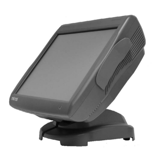
The mounting options available for the Workstation 5 and 5A also apply to the PCWS 2015. The Adjustable Stand The Adjustable Stand converts the low profile PCWS 2015 into an adjustable display design. The stand has a weighted base for stable operation, generous cable area, a compartment for storing a printer power supply, and locking hinges to allow the workstation to be positioned between 25°... -
Page 23: Power Supply Compartment
Figure 1-6: Adjustable Stand - Power Supply Compartment Three pairs of mounting holes are provided at the left, right and rear of the plate sized for optional Adjustable Stand Mounting Bracket. PCWS 2015 Setup Guide - 2nd Edition 1-11... -
Page 24: Lcd Customer Display Options
What is the PCWS 2015 Features LCD Customer Display Options The PCWS 2015 supports the 240x64 LCD Customer Display and the Protege Customer Display System. Integrated, Pole and Adjustable Stand Mounted versions are available, as detailed in the following pages. -
Page 25: Protege Lcd Customer Display System
During idle times, the Protege can display customized visual content (e.g. slide shows), for use as a marketing and advertising tool. Figure 1-8: The Protege Customer Display System PCWS 2015 Setup Guide - 2nd Edition 1-13... -
Page 26: Software Platform
Client Application Utility (CAL). BIOS The PCWS 2015 is based on the Phoenix SecureCore Tiano (SCT) BIOS. It is built on a decade of support for industry initiatives to handle the widest possible range of processors chip set and IO interfaces. The BIOS includes a pre-boot environment called UEFI (Unified Extensible Firmware Interface) to provide optional features such as CF Recovery. -
Page 27: Micros Cal32
Simphony, including SQL Express, Visual C++ 2008 Runtime, and POS for .NET. POS Application The PCWS 2015 is shipped without a Point of Sale application installed. The MICROS Client Application Loader (CAL) included with each unit can connect to any MICROS application server and download the application in minutes. -
Page 28: Power Management States
It is not safe to disassemble the workstation when in this state. Power supply components remain energized, presenting a shock hazard. Always remove the AC power cord from the IO Panel before disassembling the PCWS 2015. • The Operating System and POS application are operating. RAM contents are maintained. -
Page 29: Pcws 2015 Power Management Table
Warm boot is called by the NOPOWER CAL. then ON NOPOWER AC Power AC Power fails and restored NOPOWER Failure AC Power AC Power fails and is Failure restored Figure 1-9: PCWS 2015 Power Management States PCWS 2015 Setup Guide - 2nd Edition 1-17... -
Page 30: Specifications
What is the PCWS 2015 Specifications Specifications The PCWS 2015 conforms to the following specifications. Specification Parameters Processor Selections Intel Celeron P4505, Dual Core 1.8GHz, or Intel i5-520, Dual Core, 2.4GHz IO Controller QM57 Platform Controller Hub Display 15” TFT LCD (1024x768) -
Page 31: Approvals
Weight 10.5 lbs. (4.7 kg) / Shipping weight 14.0 lbs. (6.35 kg) Case Material PC-ABS Plastic Physical Dimensions See Appendix A Approvals The PCWS 2015 meets the following safety and environmental certifications. Directive Specification Year Safety EN 60950-1:2006+A11+A1 2010 (2006/95/EC) - Page 32 What is the PCWS 2015 Approvals 1-20 PCWS 2015 Setup Guide - 2nd Edition...
- Page 33 Chapter 2 PCWS 2015 BIOS This chapter describes the PCWS 2015 BIOS. Supported BIOS Versions include: • O1201r (Revision C System Board Only) • O1301 (Revision C System Board Only) • O1301g (Revision D or later System Boards Only) In this chapter Starting BIOS Setup Utility ...............
-
Page 34: Pcws 2015 Bios Version And System Board Compatibility
MICROS recommends you do not change BIOS fields unless specifically instructed to do so. • PCWS 2015 specific settings are contained in the Advanced -> Special Menu. • To control the IO Panel USB Ports through the BIOS, refer to page 2-20. - Page 35 A section of the Phoenix SecureCore Tiano Setup Main screen shown below appears. Figure 2-1: PCWS 2015 BIOS Setup Main Screen (O1301g or later) To adjust the System Date and Time, follow the help instructions shown at the bottom of the screen.
-
Page 36: System Information Screen
The MICROS BIOS Version and build time are displayed. Processor Type and Speed The Processor Number and Clock Speed are displayed in this field. Two processors are available, listed below. • i5 520E @ 2.40GHz. • Celeron P4505 @ 1.8GHz. PCWS 2015 Setup Guide - 2nd Edition... -
Page 37: System Memory Speed
Memory Channel A Slot 0 This field displays the SO-DIMM installed in the SO-DIMM1 socket. Memory Channel B Slot 0 This field displays the SO-DIMM installed in the SO-DIMM2 socket. PCWS 2015 Setup Guide - 2nd Edition... -
Page 38: Advanced
The Advanced tab contains the majority of BIOS settings listed under a number of headings shown in Figure 2-3, below. Figure 2-3: PCWS 2015 BIOS Advanced Menu (Version O1201r) Note: All PCWS 2015 specific fields are contained in the ‘Special Configuration’ Menu. Select Language Three selections are available. -
Page 39: Boot Configuration
Enables a Graphical POST, including animation, sound, icons, advertisements, and other multi-media objects that may be configured by the OEM. On the PCWS 2015, this is confined to the Blue splash screen with MICROS logo. The BIOS Version is displayed in the upper left corner of the splash screen. - Page 40 When Enabled, this option will skip some tests to speed up the POST. Load OPROM [On Demand] Load all Option ROMs or on demand according to the boot device. Boot Priority [UEFI First] Select the priority of the boot option between UEFI and legacy devices. PCWS 2015 Setup Guide - 2nd Edition...
-
Page 41: Acpi Configuration
Advanced ACPI Configuration The PCWS 2015 defines two thermal zones, SYS and CPU. Each zone contains a sensor coupled to fan controllers located in the Super IO. At start-up, the BIOS configures the fan controllers using the default active trip points for the CPU and SYS fans. - Page 42 ACPI features of the hardware. The Fixed ACPI Description Table starts with the FCAP signature. The FADT describes the implementation and configuration details of the ACPI hardware registers on the platform. 2-10 PCWS 2015 Setup Guide - 2nd Edition...
-
Page 43: Processor Configuration
Enabled XD [Enabled] Enable or Disable Memory segregation for improved security. Machine Check [Enabled] Enable or Disable Machine Check exception handling. PCWS 2015 Setup Guide - 2nd Edition 2-11... - Page 44 The higher the c-state, the more power saving actions are performed. Systems like the PCWS 2015 implement C-states by having the processor control the states. The chipset exchanges messages with the processor as part of the C-state flow.
- Page 45 PCIe SR-IOV Support [Disabled] Enables support for a ‘Single Root I/O Virtualization’ which enables sharing of a single I/O device among multiple virtual machines. PCWS 2015 Setup Guide - 2nd Edition 2-13...
-
Page 46: Hdd Configuration
AHCI - Advanced Host Controller Interface. A new SATA programming interface developed through a joint industry effort. AHCI defines transactions between the SATA controller and software and requires an operating system such as Windows 7 to support all features. 2-14 PCWS 2015 Setup Guide - 2nd Edition... - Page 47 PCWS 2015. Serial ATA Port 0 [ID String - if installed] Displays the ID String of the SATA HDD/SSD installed in the PCWS 2015 Drive Bay 1 (Rear) in this example, an Intel X25-V 40GB Solid State Drive is installed in Bay 1.
-
Page 48: Imc Configuration
(VT-d) by reporting the I/O Device assignments to VMM through DMAR ACPI Tables. > Video Configuration The following video BIOS fields do not apply to the PCWS 2015. Always Enable PEG [Disabled] PEG0 (Processor PCI Express Port 0) are PCI Express lanes connected directly to the processor and intended for ‘graphics card attach.’... - Page 49 IGD - Boot Type [CRT + LFP] Determines the video device that will be active during POST. On the PCWS 2015, CRT refers to the IO Panel VGA connector and LFP refers to the workstations 15” LCD. If an LCD monitor is connected to the IO Panel VGA connector, it will display the POST messages.
- Page 50 IGD - LCD Panel Type [1024x768 LVDS Color] This field is set to match the standard PCWS 2015 15” LCD. IGD - Panel Scaling [Auto] Select the Panel Scaling method used by the IGD. This feature may not be supported.
-
Page 51: South Bridge Configuration
Enables support for the pair of Enhanced Host Controllers Interface controllers which support up to 14 USB Ports. The PCH also contains two Rate Matching Hubs (RMH) that support USB full-speed, and low-speed capable. PCWS 2015 Setup Guide - 2nd Edition 2-19... - Page 52 PCWS 2015 BIOS Advanced USB Ports Per-Port Disable Control [Enabled] This selection controls the PCWS 2015 USB ports on Revision C or D System Boards. By default, all USB ports are enabled.l NOTICE: Updating the PCWS 2015 BIOS or using the ‘Load Setup Defaults’...
- Page 53 Configures the DMI settings of the PCI Express controller. > PCI Express Root Port 1 Config PCI Express Root Port 1 is assigned to CN15, a PCIe x1 connector. This connector is currently not assigned. PCWS 2015 Setup Guide - 2nd Edition 2-21...
- Page 54 Auto Detects PCI Express Active State Power Management Settings. HOT PLUG [Disabled] Enable or Disable Hot Plug events on PCI Express Root Port 2. URR [Disabled] Enable or Disable PCI Express Root Port 2 Unsupported Request Reporting. 2-22 PCWS 2015 Setup Guide - 2nd Edition...
- Page 55 Enable or Disable the PCI Express Root Port 2 Power Management Event Interrupt generation mechanism. PME SCI [Disabled] Enable or Disable the PCI Express Root Port 2 Power Management Event System Control Interrupt mechanism. PCWS 2015 Setup Guide - 2nd Edition 2-23...
-
Page 56: Network Configuration
Enable or Disable support for LAN Option ROM Selection. Wake on LAN [Enable] Enable or Disable the Wake On LAN feature. ASF Support [Enable] Enable or Disable support fro the Alert Standard Format Specification. 2-24 PCWS 2015 Setup Guide - 2nd Edition... -
Page 57: Winbond Configuration
PCWS 2015 BIOS Advanced Winbond Configuration The Figure below displays the pre-assigned PCWS 2015 Serial Port IO Address, and Interrupt resources for each COM Port. The COM Port resources apply to all BIOS Versions and System Board Revisions and are shown for reference only. -
Page 58: Special Configuration
Special Configuration The Special Configuration screen is shown in Figure 2-14, below. It contains custom BIOS fields specific to the PCWS 2015. This includes settings to determine the Powered RS232 Voltage, Cash Drawer Voltage or enable the WIN32 Factory Recovery feature. - Page 59 Each Recovery CF contains a pre-boot environment and start-up scripts that automatically start the GHOST utility and transfer the factory (or user specified) image to the PCWS 2015 boot device. When the image transfer is complete, the workstation re-starts and boot order is reset to the previous configuration.
-
Page 60: Amt Configuration
Enable or Disable write protection for the ME Firmware for the AMT SPI device. Intel AMT Password Write Protect [Disabled] Enable or Disable the AMT Password write protect feature. Password is writable when set to Enable. 2-28 PCWS 2015 Setup Guide - 2nd Edition... - Page 61 OS Timer [1] Set the OS Watchdog Timer value. KVM Feature [Disabled] Enable or Disable the KVM feature. ME FW Downgrade [Disabled] Enable or Disable the ability to downgrade the Intel ME firmware. PCWS 2015 Setup Guide - 2nd Edition 2-29...
-
Page 62: Me Configuration
Display the Management Engine Firmware version stored in U54. ME Firmware [Full SKU Firmware] Display the Management Engine firmware capabilities. End of BIOS Message [Disabled] Enable or Disable the BIOS sending an End of POST message to the Management Engine. 2-30 PCWS 2015 Setup Guide - 2nd Edition... -
Page 63: Security
Figure 2-16: BIOS Security Menu (Default Settings) Set Supervisor Password To configure the workstation to require a password to start the PCWS 2015 Recovery CF, set the Supervisor Password as described below. Once the Supervisor Password is configured, it will be required to enter the BIOS Setup menu in addition to starting the optional PCWS 2015 Recovery CF. - Page 64 Confirm the password by typing it again and pressing enter. • The Supervisor password will be required to enter the Phoenix SecureCore Tiano Setup Menu and to start the optional PCWS 2015 Recovery CF. Optionally, scroll to the ‘Supervisor Hint String’ field and press Enter to type a word or phrase that can serve as a hint for the Supervisor Password.
-
Page 65: Boot
HDD0. ATA HDD0 - ATA HDD3 The PCWS 2015 supports booting from up to four SATA devices, ATA HDD0 through ATA HDD3. ATA HDD0: and ATA HDD1: are reserved for SATA drives located in the Drive Bay, while ATA HDD3: supports the SATA CF Riser Card on Revision C System Boards and ATA HDD2: on Revision D System Boards. - Page 66 Refers to the Unified Extensible Firmware Interface (UEFI). Note: If no hard drives or bootable USB devices are attached to the unit, the BIOS will display the UEFI Shell. PCI LAN:IBA GE Slot 00C8 v1330 Enables network boot. 2-34 PCWS 2015 Setup Guide - 2nd Edition...
-
Page 67: Exit
Selecting this field causes the BIOS to discard all changes, but does not exit the Setup Menu. Save Changes Save all changes on all menus to CMOS. The workstation remains at the BIOS Exit menu and does not restart. PCWS 2015 Setup Guide - 2nd Edition 2-35... - Page 68 PCWS 2015 BIOS Exit 2-36 PCWS 2015 Setup Guide - 2nd Edition...
- Page 69 In this chapter Disassembling the PCWS 2015 ............3-2 System Board Description ...............3-12 System Board Technical Description..........3-23 Installing Options................3-31 Reassembling the PCWS 2015 ............3-48 PCWS 2015 Setup Guide - 2nd Edition...
-
Page 70: Disassembling The Pcws 2015
The following procedure describes how to disassemble the unit and access the system board and peripheral components. CAUTION: DOUBLE POLE/NEUTRAL FILTERING The PCWS 2015 Power Supply contains a permanently connected fuse in the neutral line. After fuse operation, parts of the power supply remain energized and present a shock hazard as long as the AC Power Cord is connected. - Page 71 J19. Figure 3-2: Removing the LCD/Touchscreen Assembly 6. If a Finger Print reader or other option is attached to the top cover, remove the interface cable from the System Board connector. PCWS 2015 Setup Guide - 2nd Edition...
-
Page 72: Resistive Touchscreen
For more information about each LCD/Touchscreen Assembly, see pages 3-30 and 3-31. The PCWS 2015 Base The PCWS 2015 base originates from the Workstation 5A, and adds about 10mm in overall height. The 10mm increase in height combined with a new copper bonding process to eliminate the faraday cage found in the Workstation 5A, allows a pair of laptop form factor SATA II drives to be installed in the base, under the System Board as shown in Figure 3-7. -
Page 73: System Board Revision C
What’s Inside? Disassembling the PCWS 2015 Figure 3-3 below, points out the major components of the PCWS 2015 base with the Revision C System Board. Figure 3-3: PCWS 2015 Base Assembly with Revision C System Board System Board Revision C •... -
Page 74: System Board Revision D
What’s Inside? Disassembling the PCWS 2015 Figure 3-4, below points out the components of the PCWS 2015 base with the Revision D System Board installed. Figure 3-4: PCWS 2015 Base Assembly with Revision D System Board System Board Revision D The Revision D System Board includes the following changes. -
Page 75: Power Supply Cover And Fans
SODIMM1 Socket. The SYS fan runs only when necessary, drawing ambient air across the SO-DIMM sockets and the remainder of the System Board before exiting the right side of the base. The System Fan will be removed after the first 1000 units. PCWS 2015 Setup Guide - 2nd Edition... -
Page 76: Removing The Power Supply Cover/Air Duct
4. Remove the Power Supply cover and integrated fan, then remove the fan cable from J11. o Do not operate the PCWS 2015 without the Power Supply Cover installed and the CPU fan connected to J11. PCWS 2015 Setup Guide - 2nd Edition... -
Page 77: Drive Bay
What’s Inside? Disassembling the PCWS 2015 Drive Bay Figure 3-7 shows the PCWS 2015 base with the system board removed to expose the drive bay. Each drive is installed/removed from access panels on the bottom of the unit. The copper bonding process appears as a shiny silver coating on most of the interior surfaces. -
Page 78: Cf Riser Cards
DMA Enabled CF Card used in the WS5A returns. SATA CF Riser XBRG15 (Revision C System Board Only) The PCWS 2015 with a Revision C board uses a version of the CF Riser Card called the SATA CF Riser Card. Unlike the original CF Riser Card, the SATA CF Riser Card contains active circuitry in the form of a SATA to IDE bridge and uses a modified CF bracket as shown below. -
Page 79: Dma Enabled Cf Card Xbrb36 (Revision D Or Later System Board)
Workstation 5A and 5A DC. The left side of shows a DMA Enabled CF Riser Card and bracket from the Workstation 5A while the right side displays the PCWS 2015 SATA CF Riser Card and Bracket. Figure 3-10: PCWS 2015 CF Riser Cards Compared... -
Page 80: System Board Description
What’s Inside? System Board Description System Board Description This section displays a Block Diagram of the PCWS 2015, then goes on to point out the System Board components, connectors and jumpers. PCWS 2015 Revision C System Board /w Resistive Touchscreen... - Page 81 What’s Inside? System Board Description PCWS 2015 Revision C System Board /w Optional Capacitive Touchscreen Figure 3-12: Block Diagram /w Rev C System Board and Optional Capacitive Touchscreen PCWS 2015 Setup Guide - 2nd Edition 3-13...
-
Page 82: Pcws 2015 Revision D System Board /W Resistive Touchscreen
PCWS 2015 Revision D System Board with Resistive Touchscreen The Revision D System Board uses the DMA Enabled CF Riser Card and adds support for IO Panel USB Control. Figure 3-13: PCWS 2015 Block Diagram /w Revision D System Board 3-14 PCWS 2015 Setup Guide - 2nd Edition... -
Page 83: Pcws 2015 System Board Revision C Primary Components
What’s Inside? System Board Description PCWS 2015 System Board Revision C Primary Components Figure 3-14: System Board Revision C - Primary Components PCWS 2015 Setup Guide - 2nd Edition 3-15... -
Page 84: Pcws 2015 System Board Revision C Connectors
What’s Inside? System Board Description PCWS 2015 System Board Revision C Connectors The Figure below shows all connectors on the Revision C Board. Figure 3-15: System Board Revision C - Connectors 3-16 PCWS 2015 Setup Guide - 2nd Edition... -
Page 85: Pcws 2015 System Board Revision D Primary Components
What’s Inside? System Board Description PCWS 2015 System Board Revision D Primary Components Figure 3-16: System Board Revision D Primary Components PCWS 2015 Setup Guide - 2nd Edition 3-17... -
Page 86: Pcws 2015 System Board Revision D Connectors
What’s Inside? System Board Description PCWS 2015 System Board Revision D Connectors The Revision D System Board introduces a new LVDS Connector. Figure 3-17: System Board Revision D Connectors 3-18 PCWS 2015 Setup Guide - 2nd Edition... -
Page 87: Pcws 2015 System Board Revision C And D Jumpers And Switches
What’s Inside? System Board Description PCWS 2015 System Board Revision C and D Jumpers and Switches The Revision D System Board adds a new configuration jumper. Figure 3-18: System Board Revision C and D Jumpers and Switches PCWS 2015 Setup Guide - 2nd Edition... -
Page 88: System Board Jumper Configuration
Board jumpers. SLSW1 Touchscreen Select (Revision C and D) The PCWS 2015 System Board uses a slide switch to select the touch screen interface, detailed below. SLSW1 is a low profile surface mount DPDT slide switch in series with USB7, used for the touch screen interface. -
Page 89: J22 - Lcd Size Select (Revision D System Board Only)
Manufacturing or Debug mode only. In normal operation the jumper is not installed. Figure 3-22 below. Figure 3-22: Configuration Jumper J30 A procedure for updating the Intel Management Engine Firmware was not available at press time. PCWS 2015 Setup Guide - 2nd Edition 3-21... -
Page 90: Sw3 - Recovery Button
When the Blue splash screen appears, press [F2] to enter the BIOS Configuration screen. o Refer to Chapter 3 to selectively disable USB Ports USB1 through USB6 as required. 3-22 PCWS 2015 Setup Guide - 2nd Edition... -
Page 91: System Board Technical Description
What’s Inside? System Board Technical Description System Board Technical Description The available PCWS 2015 Processors are based on the low power-high performance 45nm Nehalem micro-architecture, and consists of a two-chip platform. The two-chip platform consists of the Processor and Platform Controller Hub (PCH) a configuration that enables higher performance, lower cost, and smaller footprint. -
Page 92: System Memory Support
The integrated graphics controller contains several types components including the graphics engines, planes, pipes, port and the Intel FDI. The HD Graphics controller includes the following features: 3-24 PCWS 2015 Setup Guide - 2nd Edition... -
Page 93: Intel Flexible Display Interface (Fdi)
2.7 Gbps and uses ANSI 8b10b encoding. QM57 General Features The QM57 PCH on the PCWS 2015 system board is part of a larger family of Intel 5 Series Chipsets encompassing home, office and mobile applications. -
Page 94: Usb 2.0 Ports
The PCH contains two SPI Interfaces. o The SPI0 channel is dedicated to the Management Engine firmware stored in U54. o The SPI1 channel is dedicated to the System BIOS chip, U55. 3-26 PCWS 2015 Setup Guide - 2nd Edition... -
Page 95: Sata (Serial Attached Ata)
DMA input engines. The output DMA engines move digital data from system memory to the D-A converter in the codec. The input DMA engines move digital data from the A-D converter in the codec to system memory. PCWS 2015 Setup Guide - 2nd Edition 3-27... -
Page 96: Gpio
System Board Technical Description The PCWS 2015 System Board uses a Realtek ALC268-VB1 HD Audio Codec. Like the WS5/WS5A case work on which it based, the PCWS 2015 includes two speakers mounted to the left and right side of the base. A two watt per channel amplifier drives the speakers. -
Page 97: Lcd And Touchscreen Assembly
What’s Inside? System Board Technical Description LCD and Touchscreen Assembly The PCWS 2015 currently ships with a 15” Resistive Touchscreen and AUO LCD with LED Backlights. The available Capacitive Touchscreen option is shown on the next page. Resistive Touchscreen Details The LCD/Touchscreen Assembly with resistive touchscreen is shown in Figure 3-25, below. -
Page 98: Optional Capacitive Touchscreen Details
The LCD/Touchscreen Assembly with the optional capacitive touchscreen is shown in Figure 3-26. Figure 3-26: PCWS 2015 /w Optional Capacitive Touchscreen and LED Backlights The Capacitive Touchscreen Option adds the Capacitive Touchscreen Interface Board and interface cable. The capacitive touchscreen plugs directly into the Capacitive Touchscreen Interface Board. -
Page 99: Installing Options
Magnetic Card Reader The PCWS 2015 uses the same Magnetic Card Reader assembly as the Workstation 5 and 5A. The reader head and interface cable is pre-mounted to a plastic channel located along the right side of the base. -
Page 100: Ddr3 So-Dimms
This section specifies the approved memory devices and describes how to remove and replace DDR3 SO-DIMMs. The PCWS 2015 System Board includes a pair of SO-DIMM sockets SO-DIMM1, accessible on the top of the system board, and SO-DIMM2 accessed by removing an access door on the base. - Page 101 • Insert the SO-DIMM into the socket at a 30° angle. When it is fully inserted, press down to lock the retension clips into place. Figure 3-30: Installing a SO-DIMM PCWS 2015 Setup Guide - 2nd Edition 3-33...
-
Page 102: Removing The Io Door
What’s Inside? Installing Options Removing the IO Door The PCWS 2015 IO Door includes a new release tab to avoid having to bend the door to remove or install it. Figure 3-31 shows an example of the IO Door release. -
Page 103: Installing The Rear Lcd Customer Display
Installing the Rear LCD Customer Display This procedure describes how to attach the Integrated LCD Customer Display to the PCWS 2015. The display is provided as a complete assembly, ready to install. 1. Remove the AC power cable from the unit. -
Page 104: Pole Lcd Customer Display
This procedure describes how to install and connect the Pole LCD Customer Display to a PCWS 2015. The pole version is provided as a kit consisting of the LCD Display Assembly /w 5 ft. cable, 18” pole, base, extension cable, and nut. - Page 105 The DiagUtility Main Screen is displayed. 6. Touch the ‘Cust Disp’ tab. Press the [Send] button to send a message to the customer display. o The message should display on the LCD Customer Display. PCWS 2015 Setup Guide - 2nd Edition 3-37...
-
Page 106: Pcws 2015 And Adjustable Stand And Pole Display
What’s Inside? Installing Options PCWS 2015 and Adjustable Stand and Pole Display The Adjustable Stand Pole Display can be used with the PCWS 2015. The kit consists of a the LCD customer display, 6” Pole, mounting bracket and hardware. 1. Determine the location of the mounting bracket on the base plate. It can be mounted to the left, right, or rear of the Base Plate. -
Page 107: Protege Customer Display System - Integrated
4. Attach the 1x8 connector to USB5 as shown in the as shown in the illustration below. Figure 3-35: Installing the Protégé Integrated Customer Display • Alternately, the Prot can be connected to USB6. é é PCWS 2015 Setup Guide - 2nd Edition 3-39... -
Page 108: Protege Customer Display System - Pole Mount
é tighten the 1.5mm set screw. Figure 3-36: Attaching the Protégé Customer Display System to a 6” Pole 4. Connect the Prot to the USB5 or USB6 on the PCWS 2015 IO Panel. é é 3-40 PCWS 2015 Setup Guide - 2nd Edition... -
Page 109: Hard Drive Installation
What’s Inside? Installing Options Hard Drive Installation This section describes the PCWS 2015 Hard Drive configuration and shows how to install or remove a disk drive. CAUTION Before installing or removing disk drives, always power off the unit and remove the AC Power Cable. -
Page 110: Installing A Second Hard Disk
5. If you apply a slight downward force on the drive as you install it, the connectors can ride up and over the SATA HDD board connectors as shown at the bottom of Figure 3-39. 3-42 PCWS 2015 Setup Guide - 2nd Edition... - Page 111 This can result in the drive riding up and over the SATA Riser Card connectors as shown in Figure 3-39, below. Figure 3-39: Installing a SATA Disk Drive PCWS 2015 Setup Guide - 2nd Edition 3-43...
-
Page 112: Configuring The 2Nd Drive
When you start Disk Management, a prompt may appear requesting that you Initalize the disk before the Disk Manager can access it. Press [OK] to initalize the disk. Once the drive is initialized, it must be partitioned, formatted and a drive letter assigned. 3-44 PCWS 2015 Setup Guide - 2nd Edition... -
Page 113: Raid Overview
RAID Overview The following discusses the various options available for using a RAID on the PCWS 2015. With two drives available and RAID support included in the PCH and BIOS, basic RAID Level 0 and 1 configurations are possible. The following section provides consideration of each type, then goes on to describe how to configure the BIOS to build a two-drive RAID. -
Page 114: Building The Raid Array
RAID volumes or select recovery options should they be required. o When you enable RAID, two drives must be installed or the menu shown above does not appear. 3-46 PCWS 2015 Setup Guide - 2nd Edition... - Page 115 RAID system. Conversely, OS images created for a RAID will not boot on a single drive configuration. o RAID and non-RAID PCWS 2015 images can be obtained from the MICROS HSG Portal. o RAID and non-RAID images for the 2015 are posted in the Member Login Area of the MICROS Web Site: Members ->...
-
Page 116: Reassembling The Pcws 2015
What’s Inside? Reassembling the PCWS 2015 Reassembling the PCWS 2015 The following procedure describes how to reassemble the PCWS 2015. Procedure: 1. Before installing the power supply cover, make sure the power supply cable is routed through the cable guide located just behind the power supply as shown in the left of Figure 3-42, below. - Page 117 Figure 3-43: Top Cover Option Cable Routing 3. Place the LCD/Touchscreen Assembly to the right of the base and connect the interface cables as shown in Figure 3-44. Figure 3-44: Installing the LCD/Touchscreen Cables PCWS 2015 Setup Guide - 2nd Edition 3-49...
- Page 118 4. Install the LCD/Touchscreen Assembly in the base. The top of Figure 3-45, below shows the tabs at the rear of the assembly and the slots in the base. Insert the tabs into the base. Figure 3-45: Installing the LCD/Touchscreen Assembly 3-50 PCWS 2015 Setup Guide - 2nd Edition...
- Page 119 Figure 3-47: Installing the Top Cover 7. Tighten the captive screws to secure the cover. PCWS 2015 Setup Guide - 2nd Edition 3-51...
- Page 120 What’s Inside? Reassembling the PCWS 2015 3-52 PCWS 2015 Setup Guide - 2nd Edition...
- Page 121 IO Panel, and covers the basic operational procedures such as Factory Recovery. In this chapter Care and Handling ..................4-2 The IO Panel ....................4-5 Installation ....................4-9 Operation ....................4-12 PCWS 2015 Setup Guide - 2nd Edition...
-
Page 122: Care And Handling
Noise radiating from AC power lines throughout the site can be absorbed by MICROS AC power and communications lines and induced into the equipment. Consequently, no exposed cable dedicated to the MICROS equipment should be run in the vicinity of any AC power lines. PCWS 2015 Setup Guide - 2nd Edition... -
Page 123: Electrostatic Discharge (Esd)
However, tile or anti-static carpet is recommended in areas near the workstation. Temperature and Humidity The PCWS 2015 can operate in temperatures between 0°C (32°F) and 45°C (113°F). A constant humidity between 40% and 90% is required for proper operation of the equipment. -
Page 124: Magnetic Card Reader
Cleaning kits are available from a variety of sources including MICROS P/N 600439-003 and P/N 600439-004. Be sure to follow the instructions supplied with the cleaning kits. PCWS 2015 Setup Guide - 2nd Edition... -
Page 125: The Io Panel
USB1 - USB4 The PCWS 2015 includes four standard Type A USB 2.0 compatible ports, labeled USB1 through USB4. When the unit it shipped, all ports are enabled. For PCI-DSS compliance, all I/O Panel USB Ports (including USB5 and USB6) can be disabled through the BIOS. -
Page 126: Cash Drawer #1 - Cash Drawer #2
The bracket also includes a slot first introduced on the Workstation 5A. CF Card On the PCWS 2015, the primary role of the CF Card slot is image recovery of the primary boot device. Optional Automated Recovery CFs for supported operating systems will be available. -
Page 127: Rear Display
This connector is reserved for the Integrated 240x64 LCD Customer Display. 10/100/1000 Ethernet The PCWS 2015 includes a 10/100/1000 Ethernet Controller with a UTP modular connector. The modular connector features an integrated isolation transformer as well as a link status and network activity indicators. The interface is fully IEEE 802.3 compliant. -
Page 128: Com5
COM5 port on the Workstation 5, Workstation 5A and PCWS 2010. Use RJ45 to RS232 DB9 Adapter Cable, P/N 300319-103. +12V Out This knock-out is reserved for a future optional external power connector. PCWS 2015 Setup Guide - 2nd Edition... -
Page 129: Installation
This section describes how to install the AC adapter, and discusses the recommended method of cabling the workstation. Cabling the Adjustable Stand This procedure describes how to attach the PCWS 2015 to the Adjustable Stand. 1. Install the optional Printer Power Supply, if required. Refer to Figure 4-2. - Page 130 Installing and Operating the Workstation 2015 Installation Figure 4-3: Preparing to Attach the PCWS 2015 to the Adjustable Stand 3. Mount the cabled workstation by placing the rubber feet into the receptacles on the adjustable stand. Figure 4-4, below. Figure 4-4: Mounting the Workstation to the Adjustable Stand...
- Page 131 6. Place your peripherals near the workstation and attach cables as required. 7. Connect the AC power cord to an electrical outlet installed in accordance with the appropriate site prep guide. See Chapter 4 for more information about starting the workstation. PCWS 2015 Setup Guide - 2nd Edition 4-11...
-
Page 132: Operation
Installing and Operating the Workstation 2015 Operation Operation This section presents operational procedures for the PCWS 2015 including how to use the power button to transition the unit between the , and NOPOWER power states. PCWS 2015 Operator Features Figure 4-6 points out the location of the PC Workstation 2015 Power Button, Green Operator LED, Magnetic Card Reader, and 15”... -
Page 133: Turing The Workstation From Nopower To On
BIOS Splash Screen appears. See Chapter 2 for more information about configuring and using the PCWS 2015 BIOS. Figure 4-7: PCWS 2015 BIOS Splash Screen Example • The MICROS BIOS Version is displayed in the upper left corner of the splash screen. -
Page 134: Backlight Control
Click Start, then select ‘Install Win32 CAL Client’ from the top of the Start Menu. Backlight Control The following describes how the PCWS 2015 LCD Backlights are expected to operate. Windows 7 Professional After five minutes of inactivity, the Windows 7 ‘Balanced’ power scheme is set to dim the backlights. -
Page 135: Turing The Workstation From On To Nopower
• For POSReady2009, if you touch the power button, a ‘Shut Down Windows’ dialog box appears. Select ‘Shut down’ from the menu or press [OK] button to restart the unit. PCWS 2015 Setup Guide - 2nd Edition 4-15... -
Page 136: Controlling The Io Panel Usb Ports
IO Panel USB port. Figure 4-8: USB Per Port Enable/Disable (BIOS) 6. To disable one or more IO Panel USB ports, scroll to the individual field and press Enter. 4-16 PCWS 2015 Setup Guide - 2nd Edition... -
Page 137: System Board Revision D
When you change the status of one or more ports, it does not take effect until you restart the workstation.l NOTICE: Updating the PCWS 2015 BIOS or using the ‘Load Setup Defaults’ selection from the BIOS Exit menu re-enables all USB ports. - Page 138 The change in USB port status take effect immediately, a restart is not required. • When complete, exit the Diagnostics Utility. • Using the CMOS jumper or updating the BIOS resets all USB ports to enabled. 4-18 PCWS 2015 Setup Guide - 2nd Edition...
-
Page 139: Image Recovery
Installing and Operating the Workstation 2015 Operation Image Recovery The following general procedures can be used for PCWS 2015 Windows 7 or POSReady 2009 Recovery CF Card when available. How you start the optional Recovery CF is dependant on the System Board Revision and the BIOS installed. - Page 140 • After the image transfer completes, restart the workstation, but do not press the [F5] key. The workstation should boot from the primary boot device, a SATA hard disk or RAID. 4-20 PCWS 2015 Setup Guide - 2nd Edition...
- Page 141 SATA Disk Drive. If the recovery CF will remain installed, enter the BIOS, proceed to the Boot tab and move the ATA HDD0: selection to the top of the boot order. PCWS 2015 Setup Guide - 2nd Edition 4-21...
- Page 142 Operation Using the Magnetic Stripe Card The PCWS 2015 Magnetic Stripe Reader is mounted on the right side of the top cover as shown in Figure 4-13, below. Orient the card with the mag stripe facing towards the workstation and facing down.
-
Page 143: Calibrating The Touchscreen
3. After touching three targets you will be prompted to accept the new calibration values or run the calibration procedure again. Press [ACCEPT] to store the new calibration values and return to the desktop. PCWS 2015 Setup Guide - 2nd Edition 4-23... - Page 144 Installing and Operating the Workstation 2015 Operation 4-24 PCWS 2015 Setup Guide - 2nd Edition...
- Page 145 Chapter 5 Diagnostics This chapter includes basic troubleshooting procedures for the unit and describes how to use the PCWS 2015 Diagnostic Utility. In this chapter Basic Troubleshooting ............... 5-2 PC Workstation 2015 Diagnostic Utility ........... 5-4 PCWS 2015 Setup Guide - 2nd Edition...
-
Page 146: Basic Troubleshooting
Diagnostics Basic Troubleshooting Basic Troubleshooting This section provides a brief troubleshooting guide for common problems encountered when installing or operating the PCWS 2015. For a detailed start-up description for the 2015, see chapter 4. Problem Possible Cause Solution When the power button is... - Page 147 PCWS 2015 cannot read Mag card read head dirty or Use mag card cleaning kit mag cards. contaminated. on reader. Mag card reader defective. Replace mag stripe reader. PCWS 2015 Setup Guide - 2nd Edition...
-
Page 148: Pc Workstation 2015 Diagnostics Utility
Figure 5-1 displays Diagnostics Version 1.5 System Info screen running on a Revision C System Board with BIOS Version O1201r. Figure 5-1: The PCWS 2015 Diagnostics Utility System Information Screen (V1.5) The Figure on the next page displays the Diagnostics Version 1.6 System Info screen running on a Revision D System Board with BIOS Version O1301g. -
Page 149: Diagnostics Version
Diagnostics PC Workstation 2015 Diagnostic Utility Figure 5-2: The PCWS 2015 Diagnostics Utility System Information Screen (V1.6) A brief description of each field and button follows. Diagnostics Version This field displays the PCWS 2015 Diagnostics Utility Software version. Workstation Model This field displays the workstation model to distinguish it from other MICROS workstations. -
Page 150: Pcws Driver Version
This field displays the PC Workstation API Version. UEDCRTL Driver Version (Diagnostics Version 1.6 or later) This new API is not available in older PCWS 2015 images. The USB Port Config’ tab in the Diagnostics Utility Version 1.5 or later uses this API to control the IO Panel USB ports on System Board Revision D or later. -
Page 151: Activity Counter
Press the [View Counters] button to view the counters. All counters are stored in the registry. Figure 5-3: Diagnostics Utility Activity Counters PCWS 2015 Setup Guide - 2nd Edition... -
Page 152: Testing Cash Drawers
Digit 1 x Digit 2 + Digit 4 + Digit 6 = Password In the example, the Key is 379837. Applying the formula to this value results in 78. (3 x 7 + 8 + 7 = 36). PCWS 2015 Setup Guide - 2nd Edition... -
Page 153: Controlling The Io Panel Usb Ports
‘IO Back Panel’ illustration, located on the next page. All IO Panel USB ports are enabled when the workstation is shipped as shown in the Figure below. Figure 5-5: IO Panel USB Port Identification PCWS 2015 Setup Guide - 2nd Edition... - Page 154 The change in USB port status take effect immediately, a restart is not required. o When complete, exit the Diagnostics Utility. o Using the CMOS jumper or updating the BIOS resets all USB ports to enabled. 5-10 PCWS 2015 Setup Guide - 2nd Edition...
- Page 155 PC Workstation 2015 Low Profile............... A-2 PC Workstation 2015 Low Profile with Customer Facing Display.....A-3 PC Workstation 2015 on Adjustable Stand..........A-4 PC Workstation 2015 on Adjustable Stand /w Protege .......A-5 LCD Pole Display..................A-6 Cash Drawers....................A-7 PCWS 2015 Setup Guide - 2nd Edition...
-
Page 156: Pc Workstation 2015 Low Profile
Equipment Dimensions PC Workstation 2015 Low Profile PC Workstation 2015 Low Profile PCWS 2015 Setup Guide - 2nd Edition... -
Page 157: Pc Workstation 2015 Low Profile With Customer Facing Display
Equipment Dimensions PC Workstation 2015 Low Profile with Customer Facing Display PC Workstation 2015 Low Profile with Customer Facing Display PCWS 2015 Setup Guide - 2nd Edition... -
Page 158: Pc Workstation 2015 On Adjustable Stand
Equipment Dimensions PC Workstation 2015 on Adjustable Stand PC Workstation 2015 on Adjustable Stand PCWS 2015 Setup Guide - 2nd Edition... -
Page 159: Pc Workstation 2015 On Adjustable Stand /W Protege
Equipment Dimensions PC Workstation 2015 on Adjustable Stand /w Protege PC Workstation 2015 on Adjustable Stand /w Protege PCWS 2015 Setup Guide - 2nd Edition... -
Page 160: Lcd Pole Display
Equipment Dimensions LCD Pole Display LCD Pole Display PCWS 2015 Setup Guide - 2nd Edition... -
Page 161: Cash Drawers
Equipment Dimensions Cash Drawers Cash Drawers PCWS 2015 Setup Guide - 2nd Edition... - Page 162 Equipment Dimensions Cash Drawers PCWS 2015 Setup Guide - 2nd Edition...
-
Page 163: Appendix B: Connector And Cable Diagrams
Appendix B Connector and Cable Diagrams On the pages that follow, you will find diagrams of the PCWS 2015 I/O Panel connectors, system board connectors, and commonly used hook-up cables. A description of how each cable or connector is used is provided. -
Page 164: Io Panel Connectors
The most popular configuration of the IDN Port is the RS422 based IDN(+) mode configured as COM4. Figure B-1 shows the pin-out for this configuration. Figure B-1: IDN Connector Configured for RS422 IDN PCWS 2015 Setup Guide - 2nd Edition... -
Page 165: Com 5
Figure B-2: IDN Port Configured for RS232 COM 5 The PCWS 2015 includes one modular COM port, assigned to COM5. This is a ‘full-featured’ COM port that also appears on the WS5, WS5A, PCWS Eclipse, and PCWS 2010. Use cable P/N 300319-103 to convert this port to a DB9 connector. -
Page 166: Db9 Rs232 Connectors
IO Panel Connectors DB9 RS232 Connectors The PCWS 2015 includes two DB9 connectors assigned to COM1 and COM2. COM1 is a powered DB9F RS232 connector assigned to COM1. Pin 9 is powered. The pin-out of each port is shown below. -
Page 167: Cash Drawer 1 And 2 Connectors
Cash Drawer 1 and 2 Connectors Figure B-6: Cash Drawer Connector Diagram Remote Customer Display Connector This port supports either the 2x20 VFD customer display or the graphics based LCD customer display. Figure B-7: Customer Display Connector Diagram PCWS 2015 Setup Guide - 2nd Edition... -
Page 168: System Board Connectors
Connector and Cable Diagrams System Board Connectors System Board Connectors This section details connectors located on the PCWS 2015 system board. Magnetic Stripe Interface The internal magnetic card reader connector is CN12, located on the system board. The pin-outs for this connector are shown in Figure B-8,... -
Page 169: Hook-Up Cables
P/N 300319-102. Figure B-9: IDN Port to RS232 DB9 Male Connector Figure B-10 shows a cable diagram that adapts the IDN port to a DB25 connector. Figure B-10: IDN Port to RS232 DB25 Connector PCWS 2015 Setup Guide - 2nd Edition... -
Page 170: Com5 Rs232 Cables
Figure B-12. When the LCD Customer Display is attached directly to the Workstation, this cable plugs into the ‘Rear Display’ IO Panel connector shown in Figure B-14. Figure B-12: LCD Customer Display Housing Cable PCWS 2015 Setup Guide - 2nd Edition... - Page 171 Figure B-13: Remote Pole LCD Customer Display Assembly IO Panel Customer Display Connector The PCWS 2015 places the integrated or rear customer display connector on the IO Panel. A diagram of this connector is shown below. Figure B-14: IO Panel Integrated LCD Connector...
- Page 172 Figure B-15 shows a diagram of a standard Cat 5 Ethernet hook-up cable. This cable would be connected from a workstation or server to the system hub. Figure B-15: EIA/TIA-568-A Cat 5A Ethernet Hook-up Cable Diagram B-10 PCWS 2015 Setup Guide - 2nd Edition...
- Page 173 For example, it can be used to connect two workstations, or a server connected to a single client. Figure B-16: Cat 5 Ethernet Hook-up Cable Diagram (cross-over) PCWS 2015 Setup Guide - 2nd Edition B-11...
- Page 174 This cable brings out the RS422 signals from the IDN port connector to a 6-pin wall plate connector or directly to the IDN connector on the printing device. Figure B-17: 8-Pin to 6-Pin IDN Hook-up Cable Diagram B-12 PCWS 2015 Setup Guide - 2nd Edition...
- Page 175 Connector and Cable Diagrams Hook-up Cables Cash Drawer Extension Cable PCWS 2015 Setup Guide - 2nd Edition B-13...
- Page 176 Connector and Cable Diagrams Hook-up Cables B-14 PCWS 2015 Setup Guide - 2nd Edition...
- Page 177 A booklet prepared by the Federal Communications Commission entitled "How to Identify and Resolve Radio - TV Interference Problems" may be useful. This booklet may be ordered from the Superintendent of Documents, U.S. Government Printing Office, Washington D.C. with stock number #004-000-00345-4. PCWS 2015 Setup Guide...
- Page 178 Il est obligatoire d'utiliser pour la communication ou la réalisation d'intorfaces un cable blindé, afin d'être en conformité avec les limites légales d'émission. PCWS 2015 Setup Guide...
Need help?
Do you have a question about the PCWS 2015 and is the answer not in the manual?
Questions and answers